WO2015016122A1 - 内燃機関用ピストンの製造方法および内燃機関用ピストン - Google Patents
内燃機関用ピストンの製造方法および内燃機関用ピストン Download PDFInfo
- Publication number
- WO2015016122A1 WO2015016122A1 PCT/JP2014/069519 JP2014069519W WO2015016122A1 WO 2015016122 A1 WO2015016122 A1 WO 2015016122A1 JP 2014069519 W JP2014069519 W JP 2014069519W WO 2015016122 A1 WO2015016122 A1 WO 2015016122A1
- Authority
- WO
- WIPO (PCT)
- Prior art keywords
- piston
- internal combustion
- combustion engine
- powder
- thermal conductivity
- Prior art date
- Legal status (The legal status is an assumption and is not a legal conclusion. Google has not performed a legal analysis and makes no representation as to the accuracy of the status listed.)
- Ceased
Links
Images





Classifications
-
- F—MECHANICAL ENGINEERING; LIGHTING; HEATING; WEAPONS; BLASTING
- F02—COMBUSTION ENGINES; HOT-GAS OR COMBUSTION-PRODUCT ENGINE PLANTS
- F02F—CYLINDERS, PISTONS OR CASINGS, FOR COMBUSTION ENGINES; ARRANGEMENTS OF SEALINGS IN COMBUSTION ENGINES
- F02F3/00—Pistons
- F02F3/10—Pistons having surface coverings
- F02F3/12—Pistons having surface coverings on piston heads
- F02F3/14—Pistons having surface coverings on piston heads within combustion chambers
-
- B—PERFORMING OPERATIONS; TRANSPORTING
- B22—CASTING; POWDER METALLURGY
- B22F—WORKING METALLIC POWDER; MANUFACTURE OF ARTICLES FROM METALLIC POWDER; MAKING METALLIC POWDER; APPARATUS OR DEVICES SPECIALLY ADAPTED FOR METALLIC POWDER
- B22F7/00—Manufacture of composite layers, workpieces, or articles, comprising metallic powder, by sintering the powder, with or without compacting wherein at least one part is obtained by sintering or compression
- B22F7/06—Manufacture of composite layers, workpieces, or articles, comprising metallic powder, by sintering the powder, with or without compacting wherein at least one part is obtained by sintering or compression of composite workpieces or articles from parts, e.g. to form tipped tools
- B22F7/062—Manufacture of composite layers, workpieces, or articles, comprising metallic powder, by sintering the powder, with or without compacting wherein at least one part is obtained by sintering or compression of composite workpieces or articles from parts, e.g. to form tipped tools involving the connection or repairing of preformed parts
-
- B—PERFORMING OPERATIONS; TRANSPORTING
- B23—MACHINE TOOLS; METAL-WORKING NOT OTHERWISE PROVIDED FOR
- B23K—SOLDERING OR UNSOLDERING; WELDING; CLADDING OR PLATING BY SOLDERING OR WELDING; CUTTING BY APPLYING HEAT LOCALLY, e.g. FLAME CUTTING; WORKING BY LASER BEAM
- B23K20/00—Non-electric welding by applying impact or other pressure, with or without the application of heat, e.g. cladding or plating
- B23K20/12—Non-electric welding by applying impact or other pressure, with or without the application of heat, e.g. cladding or plating the heat being generated by friction; Friction welding
- B23K20/1215—Non-electric welding by applying impact or other pressure, with or without the application of heat, e.g. cladding or plating the heat being generated by friction; Friction welding for other purposes than joining, e.g. built-up welding
-
- B—PERFORMING OPERATIONS; TRANSPORTING
- B23—MACHINE TOOLS; METAL-WORKING NOT OTHERWISE PROVIDED FOR
- B23K—SOLDERING OR UNSOLDERING; WELDING; CLADDING OR PLATING BY SOLDERING OR WELDING; CUTTING BY APPLYING HEAT LOCALLY, e.g. FLAME CUTTING; WORKING BY LASER BEAM
- B23K20/00—Non-electric welding by applying impact or other pressure, with or without the application of heat, e.g. cladding or plating
- B23K20/12—Non-electric welding by applying impact or other pressure, with or without the application of heat, e.g. cladding or plating the heat being generated by friction; Friction welding
- B23K20/122—Non-electric welding by applying impact or other pressure, with or without the application of heat, e.g. cladding or plating the heat being generated by friction; Friction welding using a non-consumable tool, e.g. friction stir welding
- B23K20/128—Non-electric welding by applying impact or other pressure, with or without the application of heat, e.g. cladding or plating the heat being generated by friction; Friction welding using a non-consumable tool, e.g. friction stir welding making use of additional material
-
- C—CHEMISTRY; METALLURGY
- C21—METALLURGY OF IRON
- C21D—MODIFYING THE PHYSICAL STRUCTURE OF FERROUS METALS; GENERAL DEVICES FOR HEAT TREATMENT OF FERROUS OR NON-FERROUS METALS OR ALLOYS; MAKING METAL MALLEABLE, e.g. BY DECARBURISATION OR TEMPERING
- C21D9/00—Heat treatment, e.g. annealing, hardening, quenching or tempering, adapted for particular articles; Furnaces therefor
- C21D9/0068—Heat treatment, e.g. annealing, hardening, quenching or tempering, adapted for particular articles; Furnaces therefor for particular articles not mentioned below
-
- C—CHEMISTRY; METALLURGY
- C22—METALLURGY; FERROUS OR NON-FERROUS ALLOYS; TREATMENT OF ALLOYS OR NON-FERROUS METALS
- C22F—CHANGING THE PHYSICAL STRUCTURE OF NON-FERROUS METALS AND NON-FERROUS ALLOYS
- C22F1/00—Changing the physical structure of non-ferrous metals or alloys by heat treatment or by hot or cold working
-
- F—MECHANICAL ENGINEERING; LIGHTING; HEATING; WEAPONS; BLASTING
- F02—COMBUSTION ENGINES; HOT-GAS OR COMBUSTION-PRODUCT ENGINE PLANTS
- F02F—CYLINDERS, PISTONS OR CASINGS, FOR COMBUSTION ENGINES; ARRANGEMENTS OF SEALINGS IN COMBUSTION ENGINES
- F02F3/00—Pistons
-
- F—MECHANICAL ENGINEERING; LIGHTING; HEATING; WEAPONS; BLASTING
- F02—COMBUSTION ENGINES; HOT-GAS OR COMBUSTION-PRODUCT ENGINE PLANTS
- F02F—CYLINDERS, PISTONS OR CASINGS, FOR COMBUSTION ENGINES; ARRANGEMENTS OF SEALINGS IN COMBUSTION ENGINES
- F02F3/00—Pistons
- F02F3/0015—Multi-part pistons
- F02F3/003—Multi-part pistons the parts being connected by casting, brazing, welding or clamping
-
- F—MECHANICAL ENGINEERING; LIGHTING; HEATING; WEAPONS; BLASTING
- F02—COMBUSTION ENGINES; HOT-GAS OR COMBUSTION-PRODUCT ENGINE PLANTS
- F02F—CYLINDERS, PISTONS OR CASINGS, FOR COMBUSTION ENGINES; ARRANGEMENTS OF SEALINGS IN COMBUSTION ENGINES
- F02F3/00—Pistons
- F02F3/26—Pistons having combustion chamber in piston head
-
- F—MECHANICAL ENGINEERING; LIGHTING; HEATING; WEAPONS; BLASTING
- F16—ENGINEERING ELEMENTS AND UNITS; GENERAL MEASURES FOR PRODUCING AND MAINTAINING EFFECTIVE FUNCTIONING OF MACHINES OR INSTALLATIONS; THERMAL INSULATION IN GENERAL
- F16J—PISTONS; CYLINDERS; SEALINGS
- F16J1/00—Pistons; Trunk pistons; Plungers
- F16J1/01—Pistons; Trunk pistons; Plungers characterised by the use of particular materials
-
- B—PERFORMING OPERATIONS; TRANSPORTING
- B23—MACHINE TOOLS; METAL-WORKING NOT OTHERWISE PROVIDED FOR
- B23K—SOLDERING OR UNSOLDERING; WELDING; CLADDING OR PLATING BY SOLDERING OR WELDING; CUTTING BY APPLYING HEAT LOCALLY, e.g. FLAME CUTTING; WORKING BY LASER BEAM
- B23K2101/00—Articles made by soldering, welding or cutting
- B23K2101/003—Pistons
Definitions
- the present invention relates to a method of manufacturing a piston for an internal combustion engine and a piston for an internal combustion engine.
- the piston described in Patent Document 1 As a conventional piston for an internal combustion engine, for example, the one described in Patent Document 1 is known.
- the piston described in Patent Document 1 it is assumed that the piston is a cylinder injection type spark ignition engine in which fuel is injected from the fuel injection valve toward the crown surface of the piston for ignition and combustion,
- the part including the fuel collision part in which the fuel collides with the liquid and including the main combustion area is constituted by a member or structure having low thermal conductivity and low specific heat.
- the temperature raising effect at the fuel collision portion is enhanced to promote the evaporation of the fuel colliding with the piston, thereby reducing the adhesion of the fuel to the top face of the piston and discharging the deposit and smoke. Can be suppressed.
- the present invention has been made in view of such problems, and it is an object of the present invention to improve the bonding strength when providing a low thermal conductivity member on the top of a piston.
- a recess is formed on the crown surface of the piston, and the powder of the filling member having a thermal conductivity lower than that of the base material of the piston and the base material of the piston are fused in this recess and alloyed or intermetallic compound
- the mixed powder or the compact of the mixed powder mixed with the powder of the joint member which can be filled with the powder is filled, and the compact of the mixed powder or the mixed powder is solidified against the recess by a method similar to so-called friction stir welding. It was decided to form a low thermal conductivity part by phase bonding.
- the bonding strength of the low heat conducting portion to the piston base material becomes high, and the bonding quality and reliability are improved.
- FIG. 3 is a schematic explanatory view of a friction bonding machine provided for the friction bonding shown in FIG. 2; It is a figure which shows the detail of the principal part of FIG. 3, (A) is front explanatory drawing, (B) is plane explanatory drawing of the same figure (A).
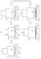
- FIG. 3 is a view showing the first embodiment of the method of the present invention, and a process explanatory view showing the details of the friction bonding step shown in FIG. 2.
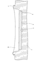
- FIG. 6 is an enlarged cross-sectional view of the low thermal conductivity portion formed by the friction bonding of FIG. 5;
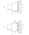
- tissue in A part of FIG. It is a figure which shows 2nd Embodiment of the method of this invention, and process explanatory drawing which shows the detail of a friction joining process.
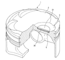
- FIG. 1 shows the structure of a piston itself used in a direct injection spark ignition engine.
- the low heat conducting portion 4 has a bottomed circular recess 5 smaller than the recess 3 formed in advance in a substantially central portion of the recess 3, and a predetermined mixed powder is formed in the recess 5. After filling, it is formed by solid phase bonding (diffusion bonding) to the recess 5 by a method similar to so-called friction stir welding.
- a mixed powder mixed with an aluminum alloy powder is used.
- the powder of the filling member and the powder of the bonding member may be in the form of flakes or chips.
- a powder of a filling member it is not limited to what was illustrated above.
- the powder of the filling member hollow ceramic beads, hollow glass beads, hollow metal spheres, as well as silica gel, silica airgel, etc. can be used.
- the powder When the mixed powder is filled into the recess 5 as described above, the powder may remain as it is, but a predetermined compact, for example, a mixed powder is pre-formed by applying a pressure in advance and pressed into a biscuit shape The powder compact may be pressed or dropped into the recess 5.
- a predetermined compact for example, a mixed powder is pre-formed by applying a pressure in advance and pressed into a biscuit shape The powder compact may be pressed or dropped into the recess 5.
- FIG. 2 shows a manufacturing procedure of a series of pistons 1 including the above-mentioned powder filling and friction bonding.
- a rough material of the aluminum alloy piston 1 is cast by a known method.
- predetermined machining is performed in a form that includes land outer diameter cutting and pin hole machining of the rough material of the piston 1 as primary machining.
- the concave portion 5 of the crown surface 2 shown in FIG. 1 may be formed by a so-called casting method at the time of casting, or may be simultaneously formed at the time of the primary machining. In any case, this process corresponds to the recess formation process.
- the powder of the above-mentioned filling member and the powder of the joining member are mixed to prepare a mixed powder, and then it is filled in the recess 5 of the piston 1.
- a green compact of the mixed powder may be produced as described above, and then it may be pushed into or dropped into the recess 5. This process corresponds to the material filling process to the recess 5.
- the piston 1 with the mixed powder filled in the recess 5 as described above is set while positioned on a friction bonding machine, and friction bonding is performed.
- This process corresponds to the friction bonding process, and the details will be described later.
- the piston 1 is taken out of the friction bonding machine and subjected to heat treatment as a post treatment.
- the purpose of this heat treatment is to remove the strain associated with plastic deformation during friction bonding and to make the strength uniform, and is performed, for example, as a housing aging treatment or an artificial aging treatment.
- the final finish cutting process is performed as a secondary machining to complete the piston 1 as a product.
- FIG. 3 shows a schematic structure of a friction bonding machine for the above-mentioned friction bonding.
- This friction bonding machine can be understood as diverting the well-known equipment for friction stir welding, and the piston 1 as a work is positioned on the bed 6 and is opposed to the bed 6
- the crosshead 7 is supported by a portal-type gantry 8 so as to be movable up and down.
- a solid cylindrical rotary tool (tool or probe) 10 for friction bonding is mounted downward on the crosshead 7 via a tool holder 9, and the rotary tool 10 is mounted on a motor 11 on the crosshead 7. It is rotationally driven through the gear box 12.
- the entire crosshead 7 including the rotary tool 10 is vertically driven by the hydraulic cylinder 13.
- a control panel 15 is attached to the friction bonding machine as well known.
- the tip surface 10a of the rotary tool 10 is a circular flat surface which is slightly larger than the diameter of the recess 5 of FIG.
- the rotary tool used for friction stir welding in the prior art is subject to the condition that projections for stirring are attached to the tip end surface, but the friction welding of the present embodiment does not require the stirring action. For this reason, the projection is not attached, and the tip surface 10a of the rotary tool 10 is a mere circular flat surface.
- FIG. 4 shows details of the mechanism that controls the positioning of the piston 1 on the bed 6 in the friction bonding machine shown in FIG. 3.
- (A) shows a front view and (B) shows the same as (A). Plane explanatory drawing is shown, respectively.
- FIGS. 4A and 4B in positioning and clamping the piston 1 on the bed 6 shown in FIG. 3, the center jig 16 on the bed 6 is covered with the piston 1 so that the piston 1 is covered.
- the crown surface 2 is supported from the back side, and a pair of split left and right side jigs 17 having protrusions 17a that can be inserted into the pin holes on the piston 1 side are moved forward by a hydraulic cylinder not shown.
- the piston 1 is pressure-restrained from both sides by the pair of left and right side jigs 17 to position and clamp. In order to prevent the deformation of the piston 1, it is desirable to support the crown surface 2 from the back side with full contact.
- the tip surface 10a of the rotary tool 10 is formed to be slightly larger than the shape of the recess 5 as described above.
- the rotary tool 10 may have a rotational form in which even the axial center moves as long as the tip surface 10 a of the rotary tool 10 does not come out of the recess 5.
- the amount of indentation of the rotary tool 10 is an amount necessary for the volume of the recess 5 to be approximately equal to the volume of the mixed powder, and this is nothing other than the porosity of the mixed powder becoming as close to zero as possible.
- the apparent density of the mixed powder in the recess 5 is increased so as to approach the true density, and due to the frictional heat between the rotary tool 10 and the recess 5 on the piston 1 side and the mixed powder, the recess 5 and the mixture It softens even if the powder is not melted, and the powders are diffusion bonded together, and solid phase bonding is also performed on the recess 5 which is the base material of the piston 1 by diffusion bonding, thereby forming the low heat conductive portion 4 of FIG. Become.
- FIG. 5 is a detailed view of the process of the above-mentioned friction bonding
- FIG. 5 (A) shows a state where the rotary tool 10 is not in contact even though the mixed powder P is filled in the recess 5; The state which the rotary tool 10 contacted around the recessed part 5 is shown, respectively.
- FIG. 6C shows a state in which the low thermal conductive portion 4 is formed by pushing the rotary tool 10 to the recessed portion 5 by a specified amount.
- the shape of the tip of the rotary tool 10 is transferred as the rotary tool 10 is pushed in, as compared to the recess 5 formed at the periphery of the low heat conducting portion 4 at first. Another large recess 18 will be formed.
- the base material of the piston 1 is pushed away, and "bare" F is generated around the low heat conducting portion 4, but this "bare” F is the secondary machining in FIG.
- the surface of the low heat conducting portion 4 is flush with the base material of the piston 1 so as to eliminate the new recess 18 made by pushing the rotary tool 10. At that time, even "barrier" F is cut and removed at the same time.
- the relationship between the diameter of the recess 5 and the diameter of the rotary tool 10 is sufficient if the diameter of the rotary tool 10 exceeds the diameter of the recess 5, and preferably the diameter of the rotating tool 10 is about 1 mm more than the diameter of the recess 5 It is desirable to be large.
- the shape of the recess 5 is not necessarily circular, but if the rotary tool 10 is circular, it is preferable that the recess 5 be also circular.
- a recess 5 with a diameter of 33 mm and a depth of 5 mm is formed on a test piece (4032-T6) of a base material made of an aluminum alloy, and 73 wt% of stabilized zirconia powder having a particle diameter of 30 ⁇ m as a filling member and a particle diameter of 30 ⁇ m as a bonding member
- the mixed powder with 27 wt% of pure aluminum powder of the above was filled in the recess 5 as a whole.
- the tool steel rotary tool 10 with a diameter of 34 mm was rotated at 800 rpm and a load was applied to push it into the test piece, and when the rotary tool was pushed about 2.9 mm, the pushing of the rotary tool 10 was finished.
- the conditions in this case are as follows.
- FIG. 6 shows a cross-sectional view of a test piece used in the friction bonding of the embodiment in the first embodiment
- FIG. 7 shows a portion A of FIG. 6, that is, the base material and the low heat conducting portion 4 newly formed. Shows an enlarged view of the tissue at the border of the.
- the low thermal conductivity portion 4 is formed on the lower side of the recess 18 formed by the pressing of the rotary tool 10 so as to fill the first recess 5.
- the base material and the pure aluminum contained as the bonding member in the mixed powder among the low thermal conductivity portion 4 are sufficiently fusion bonded and the filling member in the low thermal conductivity portion 4 is filled. It can be observed that the zirconia which is is dispersed almost uniformly. Therefore, the bonding strength of the low heat conducting portion 4 to the base material of the piston 1 becomes high, which can contribute to the improvement of bonding quality and reliability.
- FIG. 8 shows a second mode for carrying out the present invention.
- an annular rib 19 is formed in advance around the recess 5 so as to surround the recess 5, and the rib 19 is crushed at the time of friction bonding to form the mother of the piston 1.
- the rotary tool 10 is pushed into the material.
- the other processing conditions are basically the same as in the first embodiment described above.
- the surface of the low heat conductive portion 4 is a mother of the piston 1.
- FIG. 9 is a view showing a third mode for carrying out the present invention, and the same reference numerals as in FIG. 1 denote the same parts in FIG.
- a low thermal conductive portion 20 which functions as a lower heat insulating layer instead of the low thermal conductive portion 4 of FIG. It has a two-layer structure with the high thermal conductivity portion 21 as the upper layer having a high thermal conductivity.
- the lower heat conducting part 20 of the lower layer is intended for thermal insulation, while the high heat conducting part 21 of the upper layer is designed to receive heat from the flame so as to have a heat capacity sufficient to rapidly raise the temperature and evaporate the fuel.
- the functions are divided.
- the high thermal conductivity part 21 which is the upper layer should just determine the area x thickness so as to become appropriate specific heat x weight, specifically An example is shown in FIG. In FIG. 10, the same reference numerals as in FIG. 8 denote the same parts in FIG.
- borosilicate glass powder having a particle diameter of 4 ⁇ m, which is a filling member, and a pure aluminum having a particle diameter of 30 ⁇ m, which is a bonding member, as a mixed powder for the low thermal conductivity portion 20 which is the lower layer.
- the mixed powder P1 with 17 wt% of powder is filled in the recess 5 and compacted. This step corresponds to the lower layer filling step.
- the lower layer and the upper layer both contain pure aluminum powder which is a bonding member, a clear boundary between the lower heat conductive part 20 which is the lower layer and the high heat conductive part 21 which is the upper layer can not be formed. It was confirmed that the pure aluminum layer which is the portion (upper layer) 21 was diffusion bonded to the base material of the piston 1 and had a density substantially equal to that of the aluminum wrought material. Also, although the low heat conducting part (lower layer) 20 has a smaller amount of aluminum than the high heat conducting part (upper layer) 21, it holds borosilicate glass powder, and while including some gaps, the base material of the piston 1 It was confirmed that the joints were sufficiently joined. Thereby, the same effect as that of the first embodiment described above can be obtained.
- FIG. 11 shows a fourth mode for carrying out the present invention.
- the powder that is divided and filled into two layers, the lower layer and the upper layer is bonded by one-time friction welding with the rotary tool 10, while the fourth embodiment in FIG.
- each of the lower and upper layers is subjected to friction bonding with a rotary tool individually.
- the particle diameter of the filling member as the mixed powder for the low thermal conductive portion 20, which is the lower layer is the same.
- a mixed powder P 1 of 83 wt% of 4 ⁇ m borosilicate glass powder and 17 wt% of pure aluminum powder with a particle diameter of 30 ⁇ m, which is a bonding member, is filled in the recess 5 and compacted. This process corresponds to the first material filling process.
- the friction bonding is performed using the rotary tool 10. This process corresponds to the first friction bonding process.
- This process corresponds to the second material filling process.
- friction bonding is performed while crushing the remaining rib 22.
- This step corresponds to the second friction bonding step.
- conditions at the time of first and second friction bonding are basically the same as those in the first embodiment described above.
- the high thermal conductivity portion 21 which is the upper layer is formed on the low thermal conductivity portion 20 which is the lower layer as in the third embodiment.
- the low thermal conductivity portion which is the lower layer is different. It is the same in that the high thermal conductive portion 21 which is the upper layer is formed by being superimposed on the top 20.
- both the lower layer and the upper layer contain the pure aluminum powder which is a bonding member, the low heat conductive portion 20 which is the lower layer and the high heat conductive portion 21 which is the upper layer are clearly The boundary is not made, and the pure aluminum layer which is the high thermal conductivity part (upper layer) 21 is diffusion bonded to the base material of the piston 1 to have almost the same density as the aluminum wrought material. Also, although the low heat conducting part (lower layer) 20 has a smaller amount of aluminum than the high heat conducting part (upper layer) 21, it holds borosilicate glass powder and is sufficiently joined with the base material of the piston 1 become. Thereby, the same effect as that of the first embodiment described above can be obtained.
- the ribs 19 are formed in advance around the recess 5 22 is not necessarily required, and a two-layer structure can be realized even if the ribs 19 and 22 are not formed.
- the material of the high thermal conductivity portion 21 to be the upper layer may be a metal which forms an alloy or an intermetallic compound with the aluminum alloy which is a base material of the piston 1 as a bonding member.
- powders of, for example, iron, copper, nickel, magnesium, zinc, chromium and the like can be used.
- a plate-like one such as a wrought material such as aluminum, iron, copper, nickel, magnesium, zinc or chromium can be used as it is.
- the powder such as the mixed powder is softened by the frictional heat. It is based on the fact that the particles are compressed and diffusion bonded together while being deformed while being compressed. In this case, since a small amount of air will be entrained at the same time at the same time, some diffuse into the powder particles and oxygen is lost through oxidation, but some is confined in the layer while being compressed. .
- FIG. 12 is a view showing a fifth mode for carrying out the present invention, in which the above-mentioned exclusion of air is taken into consideration in friction bonding.
- the same reference numerals as in FIG. 8 denote the same parts.
- the stepped cylindrical rotary tool 24 is formed as a composite structure of an outer cylindrical portion 24a and a solid inner cylindrical portion 24b at the central portion, both of which are in the axial direction. Relative movement is possible. Further, a vacuum suction passage 25 is formed in the outer cylindrical portion 24a, and a port portion 25a at one end of the vacuum suction passage 25 is opened to the lower inner peripheral surface of the outer cylindrical portion 24a, and the other end is illustrated.
- the vacuum pump is connected to other negative pressure suction sources.
- the inner cylindrical portion 24b is lowered until the lower surface thereof becomes flush with the lower surface of the outer cylindrical portion 24a as shown in FIG. Close 25a. Thereafter, the outer cylindrical portion 24a and the inner cylindrical portion 24b are integrated and pressed while rotating the entire rotary tool 24. Thereafter, the low heat conducting portion 4 is formed as in FIG.
- the fifth embodiment even if the friction bonding is the same as in the previous embodiments, so-called diffusion bonding in vacuum is performed, so that particles having the low thermal conductive portion 4 are not The bond strength will be dramatically improved. As a result, the bonding strength of the low heat conducting portion 4 to the base material of the piston 1 becomes high, and the bonding quality and reliability are further improved.
Landscapes
- Engineering & Computer Science (AREA)
- Chemical & Material Sciences (AREA)
- Mechanical Engineering (AREA)
- General Engineering & Computer Science (AREA)
- Combustion & Propulsion (AREA)
- Materials Engineering (AREA)
- Organic Chemistry (AREA)
- Metallurgy (AREA)
- Physics & Mathematics (AREA)
- Crystallography & Structural Chemistry (AREA)
- Thermal Sciences (AREA)
- Composite Materials (AREA)
- Manufacturing & Machinery (AREA)
- Pistons, Piston Rings, And Cylinders (AREA)
- Pressure Welding/Diffusion-Bonding (AREA)
- Combustion Methods Of Internal-Combustion Engines (AREA)
Abstract
Description
・回転工具10の回転数:800rpm
・回転工具10の直径:φ34mm
・回転工具10の押し込み速度:20mm/min
・凹部5の直径:φ33mm
・混合粉末:充填部材であるジルコニアの粉末と接合部材である純アルミニウムの粉末との混合粉末(ジルコニアの粉末73wt%、純アルミニウムの粉末27wt%)
Claims (20)
- 内燃機関に用いられるピストンの製造方法であって、
前記ピストンの燃焼室を画成する冠面に凹部を形成する凹部形成工程と、
前記ピストンの母材よりも熱伝導率の低い充填部材の粉末と、前記母材と融合して合金化または金属間化合物となり得る接合部材の粉末とを混合した混合粉末またはその混合粉の成形体を前記凹部に充填する材料充填工程と、
前記混合粉末またはその混合粉末の成形体を含む前記凹部領域に回転工具を当接させて前記混合粉末またはその混合粉末の成形体を摩擦熱により軟化させることにより、当該混合粉末またはその混合粉末の成形体を前記凹部に対し固相接合して低熱伝導部を形成する摩擦接合工程と、
を含んでいる内燃機関用ピストンの製造方法。 - 請求項1に記載の内燃機関用ピストンの製造方法において、
前記摩擦接合工程では、前記凹部の全領域を回転工具の先端面で覆いながら当該回転工具を前記母材側に押し込むことにより摩擦熱を発生させるものである内燃機関用ピストンの製造方法。 - 請求項2に記載の内燃機関用ピストンの製造方法において、
前記凹部は前記冠面のうち燃料噴射弁から噴射される燃料が当たる位置に形成するものである内燃機関用ピストンの製造方法。 - 請求項2に記載の内燃機関用ピストンの製造方法において、
前記回転工具の先端面は円形の平坦面となっている内燃機関用ピストンの製造方法。 - 請求項1に記載の内燃機関用ピストンの製造方法において、
前記充填部材は、ジルコニア、コージェライト、ムライト、シリコン、シリカ、雲母、タルク、珪酸塩ガラス、アクリルガラス、有機ガラス、シリカエアロゲル、中空のセラミックビーズ、中空のガラスビーズ、中空の金属球、有機珪素化合物、セラミック繊維、チタン合金、低合金鋼、鋳鉄のうち少なくともいずれか一つを含んでいる内燃機関用ピストンの製造方法。 - 請求項1に記載の内燃機関用ピストンの製造方法において、
前記混合粉末の成形体は混合粉末を押し固めた圧粉体である内燃機関用ピストンの製造方法。 - 請求項1に記載の内燃機関用ピストンの製造方法において、
前記凹部の周囲にリブを予め形成しておき、前記摩擦接合工程では、前記リブを含む前記凹部の全領域を回転工具の先端面で覆いながら前記母材側に押し込むことにより摩擦熱を発生させるものである内燃機関用ピストンの製造方法。 - 請求項1に記載の内燃機関用ピストンの製造方法において、
前記摩擦接合工程での処理に先立って、前記凹部内の空気を真空引きする工程を含んでいる内燃機関用ピストンの製造方法。 - 請求項1に記載の内燃機関用ピストンの製造方法において、
前記摩擦接合工程での処理に続いて熱処理を施す内燃機関用ピストンの製造方法。 - 請求項9に記載の内燃機関用ピストンの製造方法において、
前記熱処理は容体化時効処理または人工時効処理である内燃機関用ピストンの製造方法。 - 内燃機関に用いられるピストンであって、
前記ピストンの燃焼室を画成する冠面に低熱伝導部が形成されていて、
該低熱伝導部は、前記ピストンの母材と融合して合金化または金属間化合物となっている接合部材を有し、該接合部材の中に前記ピストンの母材よりも熱伝導率の低い充填部材が拡散しているものである内燃機関用ピストン。 - 請求項11に記載の内燃機関用ピストンにおいて、
前記低熱伝導部は前記接合部材と前記充填部材とを回転工具との摩擦熱により前記母材に融合させたものである内燃機関用ピストン。 - 請求項12に記載の内燃機関用ピストンにおいて、
燃料噴射弁から筒内に向けて燃料を噴射して点火燃焼させる筒内噴射式内燃機関に用いられるものである内燃機関用ピストン。 - 請求項13に記載の内燃機関用ピストンにおいて、
前記低熱伝導部は前記冠面のうち前記燃料噴射弁から噴射される燃料が当たる位置に形成されている内燃機関用ピストン。 - 請求項14に記載の内燃機関用ピストンにおいて、
前記母材がアルミニウム合金である内燃機関用ピストン。 - 請求項15に記載の内燃機関用ピストンにおいて、
前記接合部材はアルミニウム合金または銅を含むものである内燃機関用ピストン。 - 内燃機関に用いられるピストンの製造方法であって、
前記ピストンの燃焼室を画成する冠面に凹部を形成する凹部形成工程と、
前記ピストンの母材よりも熱伝導率の低い充填部材の粉末と、前記母材と融合して合金化または金属間化合物となり得る接合部材の粉末とを混合した混合粉末またはその混合粉末の成形体を前記凹部に充填する下層充填工程と、
前記下層となる混合粉末またはその混合粉末の成形体よりも熱伝導率が高く母材と融合して合金化または金属間化合物となり得る高熱伝導部材またはその高熱伝導部材の粉末もしくはその粉末の成形体を前記凹部内の前記下層の上に充填する上層充填工程と、
前記上層となる高熱伝導部材またはその高熱伝導部材の粉末もしくはその粉末の成形体を含む前記凹部領域に回転工具を当接させて前記高熱伝導部材またはその高熱伝導部材の粉末もしくはその粉末の成形体を摩擦熱により軟化させることにより、当該高熱伝導部材またはその高熱伝導部材の粉末もしくはその粉末の成形体を前記凹部に対し固相接合して高熱伝導部を形成する摩擦接合工程と、
を含んでいる内燃機関用ピストンの製造方法。 - 内燃機関に用いられるピストンの製造方法であって、
前記ピストンの燃焼室を画成する冠面に凹部を形成する凹部形成工程と、
前記ピストンの母材よりも熱伝導率の低い充填部材の粉末またはその粉末の成形体と、前記母材と融合して合金化または金属間化合物となり得る接合部材の粉末またはその粉末の成形体とを前記凹部に充填する第1の材料充填工程と、
前記それぞれの粉末または成形体を含む前記凹部領域に回転工具を当接させて前記それぞれの粉末または成形体を摩擦熱により軟化させることにより、当該それぞれの粉末または成形体を前記凹部に対し固相接合して低熱伝導部を形成する第1の摩擦接合工程と、
前記低熱伝導部よりも熱伝導率が高く母材と融合して合金化または金属間化合物となり得る高熱伝導部材またはその高熱伝導部材の粉末もしくはその粉末の成形体を前記低熱伝導部上に充填する第2の材料充填工程と、
前記高熱伝導部材またはその高熱伝導部材の粉末もしくはその粉末の成形体に回転工具を当接させて前記高熱伝導部材またはその高熱伝導部材の粉末もしくはその粉末の成形体を摩擦熱により軟化させることにより、当該高熱伝導部材またはその高熱伝導部材の粉末もしくはその粉末の成形体を前記母材および前記低熱伝導部に対し固相接合して高熱伝導部を形成する第2の摩擦接合工程と、
を含んでいる内燃機関用ピストンの製造方法。 - 請求項18に記載の内燃機関用ピストンの製造方法において、
前記第1の摩擦接合工程では、前記凹部の全領域を回転工具の先端面で覆いながら当該回転工具を前記母材側に押し込むことにより摩擦熱を発生させるものであり、
前記第2の摩擦接合工程では、前記第1の摩擦接合工程で成形された凹部の全領域を回転工具の先端面で覆いながら当該回転工具を前記母材側に押し込むことにより摩擦熱を発生させるものであり、
前記第2の摩擦接合工程で使用する回転工具は、前記第1の摩擦接合工程で使用する回転工具よりも先端面の面積が大きいものである内燃機関用ピストンの製造方法。 - 請求項19に記載の内燃機関用ピストンの製造方法において、
前記凹部の周囲に予めリブを形成しておき、
前記第1の摩擦接合工程では、前記リブの一部を含む前記凹部の全領域を前記回転工具の先端面で覆いながら当該回転工具を前記母材側に押し込むものであり、
前記第2の摩擦接合工程では、残されたリブを含み且つ前記第1の摩擦接合工程で成形された凹部の全領域を前記回転工具の先端面で覆いながら当該回転工具を前記母材側に押し込むものである内燃機関用ピストンの製造方法。
Priority Applications (4)
| Application Number | Priority Date | Filing Date | Title |
|---|---|---|---|
| US14/905,175 US10151268B2 (en) | 2013-08-01 | 2014-07-24 | Method for manufacturing piston for internal combustion engine, and piston for internal combustion engine |
| JP2015529537A JP5976941B2 (ja) | 2013-08-01 | 2014-07-24 | 内燃機関用ピストンの製造方法 |
| DE112014003538.6T DE112014003538T5 (de) | 2013-08-01 | 2014-07-24 | Verfahren zum Herstellen eines Kolbens für einen Verbrennungsmotor und einen Kolben für einen Verbrennungsmotor |
| CN201480035806.2A CN105324570B (zh) | 2013-08-01 | 2014-07-24 | 内燃机用活塞的制造方法及内燃机用活塞 |
Applications Claiming Priority (2)
| Application Number | Priority Date | Filing Date | Title |
|---|---|---|---|
| JP2013160029 | 2013-08-01 | ||
| JP2013-160029 | 2013-08-01 |
Publications (1)
| Publication Number | Publication Date |
|---|---|
| WO2015016122A1 true WO2015016122A1 (ja) | 2015-02-05 |
Family
ID=52431658
Family Applications (1)
| Application Number | Title | Priority Date | Filing Date |
|---|---|---|---|
| PCT/JP2014/069519 Ceased WO2015016122A1 (ja) | 2013-08-01 | 2014-07-24 | 内燃機関用ピストンの製造方法および内燃機関用ピストン |
Country Status (5)
| Country | Link |
|---|---|
| US (1) | US10151268B2 (ja) |
| JP (1) | JP5976941B2 (ja) |
| CN (1) | CN105324570B (ja) |
| DE (1) | DE112014003538T5 (ja) |
| WO (1) | WO2015016122A1 (ja) |
Cited By (8)
| Publication number | Priority date | Publication date | Assignee | Title |
|---|---|---|---|---|
| WO2016063754A1 (ja) * | 2014-10-21 | 2016-04-28 | 日立オートモティブシステムズ株式会社 | 内燃機関のピストン製造方法および内燃機関用ピストンの摩擦封孔装置 |
| JP2017101269A (ja) * | 2015-11-30 | 2017-06-08 | 日立オートモティブシステムズ株式会社 | 内燃機関用ピストンおよび内燃機関用ピストンの製造方法 |
| WO2017122474A1 (ja) * | 2016-01-13 | 2017-07-20 | 日立オートモティブシステムズ株式会社 | ピストンの製造方法およびピストン |
| WO2017122451A1 (ja) * | 2016-01-13 | 2017-07-20 | 日立オートモティブシステムズ株式会社 | ピストンおよびピストンの製造方法 |
| WO2018029903A1 (ja) * | 2016-08-12 | 2018-02-15 | 日立オートモティブシステムズ株式会社 | 内燃機関のピストン、及び内燃機関のピストンの製造方法 |
| WO2018173548A1 (ja) * | 2017-03-22 | 2018-09-27 | 日立オートモティブシステムズ株式会社 | 内燃機関のピストン及びその製造方法 |
| WO2018198898A1 (ja) * | 2017-04-25 | 2018-11-01 | 日立オートモティブシステムズ株式会社 | ピストン |
| DE102018207874A1 (de) * | 2018-05-18 | 2019-11-21 | Federal-Mogul Nürnberg GmbH | Verfahren zum multidirektionalen Schmieden eines Kolbens |
Families Citing this family (6)
| Publication number | Priority date | Publication date | Assignee | Title |
|---|---|---|---|---|
| JP6481322B2 (ja) * | 2014-10-06 | 2019-03-13 | いすゞ自動車株式会社 | 直噴式エンジンの燃焼室構造 |
| JP6405352B2 (ja) * | 2016-09-16 | 2018-10-17 | 株式会社Subaru | 直噴内燃機関のピストン |
| DE102017207236A1 (de) * | 2017-04-28 | 2018-10-31 | Mahle International Gmbh | Kolben für eine Brennkraftmaschine |
| US10578049B2 (en) * | 2017-04-28 | 2020-03-03 | Mahle International Gmbh | Thermal barrier coating for engine combustion component |
| CN109083955B (zh) * | 2018-08-28 | 2021-02-09 | 四川中物红宇科技有限公司 | 一种用于板簧支架的槽内合金材料及板簧支架 |
| DE102019135240A1 (de) * | 2019-12-19 | 2021-06-24 | Ejot Gmbh & Co. Kg | Verbindungselement und Werkzeug zum Befestigen eines Verbindungselements auf einem Bauteil durch Reibschweißen |
Citations (6)
| Publication number | Priority date | Publication date | Assignee | Title |
|---|---|---|---|---|
| JPS6471631A (en) * | 1987-07-30 | 1989-03-16 | Sumitomo Electric Industries | Piston and manufacture thereof |
| JP2004502071A (ja) * | 2000-06-28 | 2004-01-22 | フェデラル − モウガル テクノロジー リミテッド | ピストンの製造 |
| JP2005076471A (ja) * | 2003-08-28 | 2005-03-24 | Toyota Motor Corp | ピストン及び内燃機関 |
| JP2005272919A (ja) * | 2004-03-24 | 2005-10-06 | Honda Motor Co Ltd | 複合材料の製造方法 |
| JP2007100129A (ja) * | 2005-09-30 | 2007-04-19 | Mitsui Eng & Shipbuild Co Ltd | 表面被覆方法および表面被覆膜 |
| JP2008175163A (ja) * | 2007-01-19 | 2008-07-31 | Toyota Motor Corp | 内燃機関用のピストンおよびその製造方法 |
Family Cites Families (5)
| Publication number | Priority date | Publication date | Assignee | Title |
|---|---|---|---|---|
| US5122226A (en) * | 1987-08-12 | 1992-06-16 | United Technologies Corporation | Method of making hybrid composite structures of fiber reinforced glass and resin matrices |
| JPH11193721A (ja) | 1997-10-30 | 1999-07-21 | Toyota Central Res & Dev Lab Inc | 筒内噴射式火花点火機関 |
| US20090206525A1 (en) * | 2005-06-24 | 2009-08-20 | Nippon Sheet Glass Company, Limited | Method for Producing Porous Silica Ceramic Material |
| JP2012047110A (ja) | 2010-08-27 | 2012-03-08 | Toyota Central R&D Labs Inc | 内燃機関 |
| JP5859395B2 (ja) * | 2012-07-27 | 2016-02-10 | 日立オートモティブシステムズ株式会社 | 内燃機関のピストン及びこのピストンの製造方法 |
-
2014
- 2014-07-24 DE DE112014003538.6T patent/DE112014003538T5/de not_active Ceased
- 2014-07-24 JP JP2015529537A patent/JP5976941B2/ja not_active Expired - Fee Related
- 2014-07-24 CN CN201480035806.2A patent/CN105324570B/zh not_active Expired - Fee Related
- 2014-07-24 US US14/905,175 patent/US10151268B2/en not_active Expired - Fee Related
- 2014-07-24 WO PCT/JP2014/069519 patent/WO2015016122A1/ja not_active Ceased
Patent Citations (6)
| Publication number | Priority date | Publication date | Assignee | Title |
|---|---|---|---|---|
| JPS6471631A (en) * | 1987-07-30 | 1989-03-16 | Sumitomo Electric Industries | Piston and manufacture thereof |
| JP2004502071A (ja) * | 2000-06-28 | 2004-01-22 | フェデラル − モウガル テクノロジー リミテッド | ピストンの製造 |
| JP2005076471A (ja) * | 2003-08-28 | 2005-03-24 | Toyota Motor Corp | ピストン及び内燃機関 |
| JP2005272919A (ja) * | 2004-03-24 | 2005-10-06 | Honda Motor Co Ltd | 複合材料の製造方法 |
| JP2007100129A (ja) * | 2005-09-30 | 2007-04-19 | Mitsui Eng & Shipbuild Co Ltd | 表面被覆方法および表面被覆膜 |
| JP2008175163A (ja) * | 2007-01-19 | 2008-07-31 | Toyota Motor Corp | 内燃機関用のピストンおよびその製造方法 |
Cited By (15)
| Publication number | Priority date | Publication date | Assignee | Title |
|---|---|---|---|---|
| WO2016063754A1 (ja) * | 2014-10-21 | 2016-04-28 | 日立オートモティブシステムズ株式会社 | 内燃機関のピストン製造方法および内燃機関用ピストンの摩擦封孔装置 |
| JPWO2016063754A1 (ja) * | 2014-10-21 | 2017-07-06 | 日立オートモティブシステムズ株式会社 | 内燃機関のピストン製造方法および内燃機関用ピストンの摩擦封孔装置 |
| JP2017101269A (ja) * | 2015-11-30 | 2017-06-08 | 日立オートモティブシステムズ株式会社 | 内燃機関用ピストンおよび内燃機関用ピストンの製造方法 |
| WO2017094728A1 (ja) * | 2015-11-30 | 2017-06-08 | 日立オートモティブシステムズ株式会社 | 内燃機関用ピストンおよび内燃機関用ピストンの製造方法 |
| CN108291311B (zh) * | 2015-11-30 | 2020-05-01 | 日立汽车系统株式会社 | 内燃机用活塞以及内燃机用活塞的制造方法 |
| CN108291311A (zh) * | 2015-11-30 | 2018-07-17 | 日立汽车系统株式会社 | 内燃机用活塞以及内燃机用活塞的制造方法 |
| WO2017122451A1 (ja) * | 2016-01-13 | 2017-07-20 | 日立オートモティブシステムズ株式会社 | ピストンおよびピストンの製造方法 |
| JP2017125440A (ja) * | 2016-01-13 | 2017-07-20 | 日立オートモティブシステムズ株式会社 | ピストンの製造方法およびピストン |
| WO2017122474A1 (ja) * | 2016-01-13 | 2017-07-20 | 日立オートモティブシステムズ株式会社 | ピストンの製造方法およびピストン |
| WO2018029903A1 (ja) * | 2016-08-12 | 2018-02-15 | 日立オートモティブシステムズ株式会社 | 内燃機関のピストン、及び内燃機関のピストンの製造方法 |
| WO2018173548A1 (ja) * | 2017-03-22 | 2018-09-27 | 日立オートモティブシステムズ株式会社 | 内燃機関のピストン及びその製造方法 |
| WO2018198898A1 (ja) * | 2017-04-25 | 2018-11-01 | 日立オートモティブシステムズ株式会社 | ピストン |
| JP2018184852A (ja) * | 2017-04-25 | 2018-11-22 | 日立オートモティブシステムズ株式会社 | ピストン |
| DE102018207874A1 (de) * | 2018-05-18 | 2019-11-21 | Federal-Mogul Nürnberg GmbH | Verfahren zum multidirektionalen Schmieden eines Kolbens |
| DE102018207874B4 (de) | 2018-05-18 | 2023-10-26 | Federal-Mogul Nürnberg GmbH | Verfahren zum multidirektionalen Schmieden eines Kolbens |
Also Published As
| Publication number | Publication date |
|---|---|
| US20160177864A1 (en) | 2016-06-23 |
| US10151268B2 (en) | 2018-12-11 |
| CN105324570A (zh) | 2016-02-10 |
| JPWO2015016122A1 (ja) | 2017-03-02 |
| CN105324570B (zh) | 2018-01-02 |
| JP5976941B2 (ja) | 2016-08-24 |
| DE112014003538T5 (de) | 2016-05-04 |
Similar Documents
| Publication | Publication Date | Title |
|---|---|---|
| JP5976941B2 (ja) | 内燃機関用ピストンの製造方法 | |
| CN105312755B (zh) | 铝合金工件中的侵入特征以改善铝钢点焊 | |
| US10006402B2 (en) | Piston for internal combustion engine and method for manufacturing piston | |
| US20170241372A1 (en) | Method for manufacturing piston for internal combustion engine and frictional hole sealing device for piston for internal combustion engine | |
| JP2000042781A (ja) | 凹状欠陥部の補修方法 | |
| JP6557583B2 (ja) | 内燃機関用ピストンおよび内燃機関用ピストンの製造方法 | |
| CN110352103A (zh) | 获取具有自愈合特性的零件的方法、具有自愈合特性的零件和修复零件的裂纹的方法 | |
| CN110268151A (zh) | 内燃机用活塞及其制造方法 | |
| CN107695321B (zh) | 一种在铝碳化硅复合材料表面覆盖铝箔的工艺 | |
| JP2004502071A (ja) | ピストンの製造 | |
| KR101989339B1 (ko) | 브레이징 소재용 금속복합분말, 이의 제조방법 및 이를 이용하는 브레이징 소재 | |
| JP6791385B2 (ja) | 内燃機関用ピストン及びその製造方法 | |
| JPS5815743A (ja) | 内燃機関用ピストンおよびその製造方法 | |
| WO2016103856A1 (ja) | 内燃機関用ピストンと、このピストンの製造方法及び製造装置 | |
| WO2017122451A1 (ja) | ピストンおよびピストンの製造方法 | |
| WO2020115459A1 (en) | Formation of selectively reinforced components | |
| JP2004122229A (ja) | 構造部材の成形方法 | |
| CN107649663A (zh) | 一种在铝金刚石复合材料表面覆盖钼箔的工艺方法 | |
| US20230349342A1 (en) | Manufacturing of aluminum piston with cast iron ring carrier using powder bed fusion method | |
| CN111215742A (zh) | 一种铜钨合金和铬青铜的连接方法及电触头 | |
| CN117226238A (zh) | 一种适用于低熔点金属的焊接方法 | |
| KR20240055311A (ko) | 고상접합용 계면층 | |
| JPS6149795A (ja) | 電子ビ−ム溶接によるピストン製造方法 | |
| JP2017125440A (ja) | ピストンの製造方法およびピストン | |
| JPH11320076A (ja) | 金属基複合材料製シリンダブロックの製造方法 |
Legal Events
| Date | Code | Title | Description |
|---|---|---|---|
| WWE | Wipo information: entry into national phase |
Ref document number: 201480035806.2 Country of ref document: CN |
|
| 121 | Ep: the epo has been informed by wipo that ep was designated in this application |
Ref document number: 14832619 Country of ref document: EP Kind code of ref document: A1 |
|
| ENP | Entry into the national phase |
Ref document number: 2015529537 Country of ref document: JP Kind code of ref document: A |
|
| WWE | Wipo information: entry into national phase |
Ref document number: 14905175 Country of ref document: US |
|
| WWE | Wipo information: entry into national phase |
Ref document number: 112014003538 Country of ref document: DE |
|
| 122 | Ep: pct application non-entry in european phase |
Ref document number: 14832619 Country of ref document: EP Kind code of ref document: A1 |