WO2015015908A1 - 紙送り用ローラ - Google Patents
紙送り用ローラ Download PDFInfo
- Publication number
- WO2015015908A1 WO2015015908A1 PCT/JP2014/065300 JP2014065300W WO2015015908A1 WO 2015015908 A1 WO2015015908 A1 WO 2015015908A1 JP 2014065300 W JP2014065300 W JP 2014065300W WO 2015015908 A1 WO2015015908 A1 WO 2015015908A1
- Authority
- WO
- WIPO (PCT)
- Prior art keywords
- paper
- elastic layer
- feed roller
- roller
- paper feed
- Prior art date
- Legal status (The legal status is an assumption and is not a legal conclusion. Google has not performed a legal analysis and makes no representation as to the accuracy of the status listed.)
- Ceased
Links
Images


Classifications
-
- B—PERFORMING OPERATIONS; TRANSPORTING
- B65—CONVEYING; PACKING; STORING; HANDLING THIN OR FILAMENTARY MATERIAL
- B65H—HANDLING THIN OR FILAMENTARY MATERIAL, e.g. SHEETS, WEBS, CABLES
- B65H3/00—Separating articles from piles
- B65H3/02—Separating articles from piles using friction forces between articles and separator
- B65H3/06—Rollers or like rotary separators
- B65H3/0638—Construction of the rollers or like rotary separators
-
- B—PERFORMING OPERATIONS; TRANSPORTING
- B65—CONVEYING; PACKING; STORING; HANDLING THIN OR FILAMENTARY MATERIAL
- B65H—HANDLING THIN OR FILAMENTARY MATERIAL, e.g. SHEETS, WEBS, CABLES
- B65H3/00—Separating articles from piles
- B65H3/46—Supplementary devices or measures to assist separation or prevent double feed
- B65H3/52—Friction retainers acting on under or rear side of article being separated
-
- G—PHYSICS
- G01—MEASURING; TESTING
- G01R—MEASURING ELECTRIC VARIABLES; MEASURING MAGNETIC VARIABLES
- G01R29/00—Arrangements for measuring or indicating electric quantities not covered by groups G01R19/00 - G01R27/00
- G01R29/24—Arrangements for measuring quantities of charge
-
- B—PERFORMING OPERATIONS; TRANSPORTING
- B65—CONVEYING; PACKING; STORING; HANDLING THIN OR FILAMENTARY MATERIAL
- B65H—HANDLING THIN OR FILAMENTARY MATERIAL, e.g. SHEETS, WEBS, CABLES
- B65H2404/00—Parts for transporting or guiding the handled material
- B65H2404/10—Rollers
- B65H2404/18—Rollers composed of several layers
- B65H2404/186—Rollers composed of several layers with electro-conductive layer
Definitions
- the present invention relates to a paper feed roller.
- image forming apparatuses are generally provided with a sheet feeding device that separates sheets one by one from a sheet cassette that stores sheets and sends them to an image forming unit.
- a pad retard method (FR method), a friction retard method (FRR method), and the like have been put to practical use as this paper feeding device.
- the FRR method is used. Often adopted.
- the FRR type paper feeding device includes a pickup roller that contacts the top of the paper contained in the paper cassette and draws the paper out of the paper cassette by frictional force, and a feed roller that sends out the drawn paper to the paper conveyance path. And a retard roller that is pressed against the feed roller and is applied with a rotational driving force in a direction opposite to the direction of stopping or conveying the sheet via a torque limiter.
- the retard roller when only one sheet passes through the pressure contact portion between the feed roller and the retard roller, the retard roller is driven by the feed roller due to slippage of the torque limiter and rotates in the paper transport direction, and the feed roller Send the paper in the transport direction.
- the retard roller stops or rotates in a direction opposite to the paper transport direction, and returns the paper in contact with the retard roller to the paper cassette direction. The paper in contact with the feed roller is sent out in the transport direction. As a result, double feeding of paper is prevented.
- thermosetting polyurethane or the like is used as a material constituting the elastic layer.
- Thermosetting polyurethane is often employed because it has a lower electrical resistance than EPDM and can easily suppress adhesion of paper dust due to static electricity.
- thermosetting polyurethane itself has a high hardness and a low coefficient of friction
- a plasticizer is generally blended to ensure a predetermined coefficient of friction (see, for example, Patent Document 1).
- the conventional technique has the following problems. That is, when a plasticizer is blended with thermosetting polyurethane, the electric resistance is lowered, which is effective in preventing the adhesion of paper dust due to static electricity. In recent years, a lot of paper made in foreign countries and the like with a lot of paper dust has been used, and there is a great demand for paper dust resistance. However, it has been newly found that, when a plasticizer is blended with thermosetting polyurethane, in some cases, a phenomenon (toner transfer omission phenomenon) that the image density of a portion of the paper in contact with the paper feeding roller is lowered is caused. . In particular, in the image forming apparatus that transfers toner onto the surface of the paper that slides with the retard roller when separating the paper, the toner transfer omission phenomenon is likely to occur.
- the present invention has been made in view of the above-described background, and has been obtained in an attempt to provide a paper feed roller capable of suppressing both adhesion of paper dust and toner transfer omission.
- One aspect of the present invention is a paper having an elastic layer composed of a thermosetting polyurethane containing a plasticizer, and a surface residual charge on the surface of the elastic layer being in a range of 90 to 170V. Located on the feed roller.
- the paper feeding roller has an elastic layer composed of a thermosetting polyurethane containing a plasticizer, and the surface residual charge on the surface of the elastic layer is within the above range. Therefore, the paper feeding roller can suppress both the adhesion of paper dust and toner transfer omission. This is thought to be due to the following reasons.
- the elastic layer containing the plasticizer When the surface residual charge of the elastic layer exceeds the above upper limit value, it is considered that the elastic layer containing the plasticizer is insufficiently reduced in electrical resistance, thereby causing adhesion of paper dust due to static electricity. On the other hand, when the surface residual charge of the elastic layer is less than or equal to the above upper limit value, the elastic layer containing the plasticizer has an appropriate state of low electrical resistance, which can suppress the adhesion of paper dust due to static electricity. It is considered to be.
- the pre-stage paper fed by the paper feeder has a uniform charge on the entire surface of the paper.
- the surface residual charge of the elastic layer is below the lower limit
- the charge of the portion of the paper that contacts the surface of the elastic layer flows to the elastic layer side. Therefore, a potential difference is generated between a portion of the paper that is not in contact with the surface of the elastic layer (hereinafter sometimes referred to as “non-contact portion”).
- non-contact portion a portion of the paper that is not in contact with the surface of the elastic layer
- the image density at the contact portion is lowered, and a toner transfer omission phenomenon occurs.
- the surface residual charge of the elastic layer is equal to or higher than the lower limit value, it is considered that the charge at the contact portion of the paper is difficult to escape to the elastic layer side, and the toner transfer omission phenomenon can be suppressed.
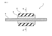
- FIG. 3 is a cross-sectional view schematically illustrating a paper feeding roller of Example 1.
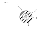
- FIG. 2 is a sectional view taken along line II-II in FIG. It is explanatory drawing for demonstrating the measuring method of the friction coefficient in an experiment example. It is explanatory drawing for demonstrating the measuring method of the surface residual charge (V) in an experiment example.
- the paper feeding roller can be used by being incorporated in a paper feeding device in an electrophotographic image forming apparatus.
- the electrophotographic image forming apparatus include a copying machine, a printer, a facsimile, a multifunction peripheral, and a POD (Print On Demand) apparatus that employs an electrophotographic system using a charged image.
- the paper feeding device has a double feed prevention mechanism that separates and feeds the paper from the paper cassette so that two or more sheets are not fed together.
- the double feed prevention mechanism may be either a friction retard method (FRR method) or a pad retard method (FR method). From the viewpoint of high accuracy, stable paper conveyance, and high reliability of the double feed prevention performance, the FRR method can be suitably employed as the double feed prevention mechanism.
- the FRR type paper feeding device includes a pickup roller that contacts the top of the paper contained in the paper cassette and draws the paper out of the paper cassette by frictional force, and a feed roller that sends out the drawn paper to the paper conveyance path.
- the paper feeding roller can be applied to any of a pickup roller, a feed roller, and a retard roller.
- the paper feed roller can be suitably used as a retard roller.
- the toner transfer omission phenomenon is likely to occur in a portion (sliding portion) that slides on the surface of the elastic layer of the retard roller in the paper, and the toner transfer omission phenomenon is easily suppressed by applying the paper feeding roller to the retard roller. Because it becomes.
- the paper feed roller has a surface residual charge on the elastic layer surface in the range of 90 to 170V.
- the surface residual charge on the surface of the elastic layer is less than 90 V, a toner transfer omission phenomenon is likely to occur. Therefore, the lower limit value of the surface residual charge on the elastic layer surface is regulated to 90V.
- the surface residual charge on the surface of the elastic layer exceeds 170V, paper dust is likely to adhere due to static electricity. Therefore, the upper limit value of the surface residual charge on the elastic layer surface is regulated to 170V.
- the surface residual charge on the surface of the elastic layer is preferably 95 V or higher, more preferably 100 V or higher, from the viewpoint of ensuring suppression of the toner transfer omission phenomenon.
- the surface residual charge on the elastic layer surface is preferably 165 V or less, more preferably 160 V or less, still more preferably 155 V or less, and even more preferably 150 V or less, from the viewpoint of ensuring the suppression of paper dust adhesion. it can.
- the surface residual charge (V) can be obtained by performing the following measurement. Under an environment of 23 ° C. ⁇ 53% RH, a grounded metal shaft is press-fitted into the paper feed roller, and the paper feed roller is rotated in the circumferential direction at a rotation speed of 70 rpm. Next, in this state, using a corotron, the distance between the core of the corotron and the elastic layer surface is 10 mm, and a corona current of 100 ⁇ A (constant current) is applied to charge the elastic layer surface. Next, the surface potential of the elastic layer surface is measured by setting the distance between the probe of the surface potential meter and the elastic layer surface to 1 mm at a position rotated 90 degrees in the rotation direction from the charging position. When the paper feed roller has a resin shaft, the resin shaft is removed and the metal shaft is directly press-fitted. The surface residual charge (V) is measured at one point at the center in the roller axial direction without moving the probe along the roller axial direction.
- thermosetting polyurethane constituting the elastic layer
- ether-based, ester-based, caprolactone-based thermosetting polyurethane, or the like can be used as the thermosetting polyurethane constituting the elastic layer.
- ether-based thermosetting polyurethane can be suitably used from the viewpoint that it is difficult to hydrolyze under the use environment of the paper feed roller and can contribute to improvement in durability.
- the thermosetting polyurethane can be a thermosetting polyurethane rubber (including an elastomer).
- the plasticizer contained in the thermosetting polyurethane has a number of ether groups in the molecule of 2 or less (when there is no ether group) from the viewpoint that the surface residual charge of the elastic layer is easily in the above range.
- a plasticizer that is included) is preferably used.
- plasticizers include acetylated monoglycerides and diesters of various glycols and various aromatic carboxylic acids. More specifically, glycerin diacetomonolaurate, glycerin diacetomono (C 8 , C 10).
- Ester glycerin diacetomonooleate, glycerin diacetomonostearate, alkylene glycol dibenzoic acid, dialkylene glycol dibenzoic acid, trialkylene glycol dibenzoic acid, and the like.
- plasticizers can be used in combination.
- the addition amount of the plasticizer is also related to the coefficient of friction on the elastic layer surface. Therefore, in this case, the addition amount of the plasticizer may be selected so that the surface residual charge on the elastic layer surface is within the above range while ensuring the friction coefficient on the elastic layer surface. Specifically, the addition amount of the plasticizer can be in the range of 10 to 50 parts by mass with respect to 100 parts by mass of the thermosetting polyurethane.
- thermosetting polyurethane has a chain extender, a crosslinking agent, a catalyst, a conductive agent, as long as the surface residual charge on the surface of the elastic layer is within the above range.
- Various additives such as a colorant may be added.
- the elastic layer can have surface irregularities capable of capturing paper dust on the surface thereof.
- the paper dust can escape to the concave portions of the surface irregularities on the surface of the elastic layer, and as a result, the adhesion of the paper powder to the convex portions of the surface irregularities, that is, the contact area with the paper is suppressed. Therefore, in this case, it is easy to suppress a decrease in the friction coefficient of the elastic layer surface due to durability, which is advantageous for improving durability and making maintenance-free.
- finer irregularities may be formed on the surfaces of the concave and convex portions constituting the surface irregularities. More specifically, the surface irregularities on the surface of the elastic layer have, for example, a textured surface having a mountain-shaped portion and a sea-shaped portion depressed from the mountain-shaped portion on the surface of the elastic layer.
- the ratio S1 / S2 between the area S1 of the mountain-shaped portion and the area S2 of the sea-shaped portion is in the range of 0.25 to 0.70, and the height of the convex portion of the fine unevenness is in the range of 3 to 25 ⁇ m. can do.
- the height of the said mountain-shaped part can be 10 micrometers or more, and the distance between the peaks of adjacent mountain-shaped parts can be 1 mm or less.
- the elastic layer may be formed on an outer peripheral surface of a shaft body made of metal having conductivity, or may be formed on an outer peripheral surface of a resin shaft body having electrical insulation. Also good. The latter is preferred. In this case, since it becomes difficult for the electric charge to flow from the elastic layer to the shaft body, the surface residual charge of the elastic layer can be easily maintained, and the above-described effects can be made stable.
- Example 1 The paper feeding roller of Example 1 will be described with reference to FIGS. As shown in FIGS. 1 and 2, the paper feed roller 1 of this example has an elastic layer 2 made of thermosetting polyurethane containing a plasticizer, and the surface residual charge on the surface of the elastic layer 2 is reduced. It is in the range of 90-170V.
- the surface residual charge on the surface of the elastic layer 2 is increased by adjusting the amount of the plasticizer added to the thermosetting polyurethane using a plasticizer having 2 or less ether groups in the molecule. It is adjusted within the range.
- the elastic layer 2 has a cylindrical shape.
- the surface of the elastic layer 2 is provided with surface irregularities (not shown) that can capture paper dust.
- the paper feed roller 1 has a resin shaft 3 having electrical insulation, and the elastic layer 2 is formed on the outer peripheral surface of the shaft 3.
- the shaft body 3 is formed in a cylindrical shape from an acetal resin.
- a metal shaft 4 provided in a sheet feeding device (not shown) in the electrophotographic image forming apparatus is inserted into the shaft 3 so that rotational driving force can be transmitted.
- PTMG polytetramethylene ether glycol
- PPG polypropylene glycol
- this urethane prepolymer was vacuum degassed at 90 ° C. for 30 minutes, and then 100 parts by mass of the urethane prepolymer, a predetermined part by mass shown in Table 1 as glycerin diacetomonolaurate, and a chain extender 3.5 parts by weight of [1,4-butanediol (1,4-BD)] and 1.5 parts by weight of a cross-linking agent [trimethylolpropane (TMP)] are mixed and stirred for 2 minutes under reduced pressure.
- TMP trimethylolpropane
- the cored bar is coaxially set in the through hole of the molding die, the opening portions at both ends are closed with a cap die, the molding space is filled with a predetermined elastic layer forming material, and then the molding die was placed in an oven to heat cure the urethane prepolymer (150 ° C. ⁇ 60 minutes).
- the elastic layer comprised from the thermosetting polyurethane containing a plasticizer was formed in the outer peripheral surface of a metal core, and it removed after that, and the elastic layer was extracted from the metal core, and was cut
- each elastic layer having a cylindrical shape with an outer diameter of ⁇ 24 mm, an inner diameter of ⁇ 14 mm, and a length of 29.5 mm was obtained.
- a cylindrical shaft body made of acetal resin was press-fitted into the cylinder of each elastic layer. As a result, Sample 1 to Sample 8 paper feed rollers were obtained.
- JIS-A hardness The JIS-A hardness of the elastic layer surface of each sample paper feed roller was measured.
- the friction coefficient of the elastic layer surface was measured for the paper feed roller of each sample. Specifically, as shown in FIG. 3, the PPC paper 50 is pressed against the paper feed roller 1 from below by a flat plate 52 through a polytetrafluoroethylene sheet 51 [pressing load (W) 2.94N. ⁇ did.
- the flat plate 52 is rotatable about one end edge 52a parallel to the axis of the paper feed roller 1, and the polytetrafluoroethylene sheet 51 is fixed to the surface of the other end side 52b of the flat plate 52, and PPC It plays the role of allowing the paper 50 to slide.
- the surface residual charge on the elastic layer surface was measured for each sample paper feed roller. Specifically, as shown in FIG. 4, the resin shaft body 3 of the paper feed roller 1 was removed, and instead the metal shaft body 4 was directly press-fitted. The metal shaft body 4 is grounded and configured to be rotatable at a predetermined rotational speed. Then, in an environment of 23 ° C.
- the paper feeding roller 1 is rotated in the circumferential direction at a rotational speed of 70 rpm, and the corotron C is used (using a DC power source), and the core C1 and the elastic layer of the corotron C
- the surface of the elastic layer 2 was charged by applying a corona current of 100 ⁇ A (constant current) at a distance of 10 mm from the surface.
- the surface potential of the surface of the elastic layer 2 is measured at one point in the center of the roller axis direction at a position rotated 90 degrees in the rotation direction from the charging position with a distance of 1 mm between the probe P of the surface potential meter and the surface of the elastic layer 2. did. This was defined as the surface residual charge on the surface of the elastic layer 2 in the paper feed roller 1 of each sample.
- the toner transfer omission was evaluated for the paper feed roller of each sample. More specifically, the paper feeding roller was incorporated as a retard roller of a paper feeding device in an electrophotographic multifunction machine (“imageRUNNER ADVANCE C5051” manufactured by Canon Inc.). At this time, the setting of the torque limiter of the retard roller was changed to 600 gf ⁇ cm so that the retard roller was stopped when the paper was passed. As a result, the retard roller and the paper slide. Then, a halftone image (black 25%) was output in an environment of 23 ° C. ⁇ 53% RH.
- the output image is visually confirmed, and when the image density unevenness does not occur in the portion of the paper sliding with the elastic layer surface of the retard roller, the toner transfer omission phenomenon is suppressed as “A”, When the image density unevenness occurred, the toner transfer omission phenomenon could not be suppressed, and “C” was assigned.
- the paper dust resistance of each sample paper feed roller was evaluated. More specifically, the paper feeding roller was incorporated as a retard roller of a paper feeding device in an electrophotographic multifunction machine (“imageRUNNER ADVANCE C5051” manufactured by Canon Inc.). Then, after passing 300,000 plain papers in an environment of 23 ° C. ⁇ 53% RH, the friction coefficient (the friction coefficient after durability) was measured by the above method. The case where the post-endurance friction coefficient is 1.3 or more is “A” when the paper dust adhesion is suppressed and the paper dust adhesion is suppressed, and the post-endurance friction coefficient is less than 1.3. In addition, “C” was given because the adhesion of paper dust could not be suppressed.
- Table 1 summarizes the relationship between the plasticizer addition amount and the surface residual charge of the elastic layer, various measurement results, and evaluation results for the paper feed rollers of each sample.
- thermosetting polyurethane constituting the elastic layer does not contain a plasticizer. Therefore, the paper feeding roller of Sample 6 has a high hardness of the elastic layer and a low initial friction coefficient. Further, the coefficient of friction after durability is low, and the adhesion of paper dust cannot be suppressed.
- the paper feed roller of Sample 7 has a surface residual charge of 80 (V) on the elastic layer surface, which is below the lower limit of the surface residual charge specified in the present application. Therefore, the paper feeding roller of Sample 7 cannot suppress the toner transfer omission phenomenon. This is because the portion of the paper that slides with the surface of the elastic layer of the retard roller (sliding portion) escapes to the elastic layer side, so that the portion of the paper that does not slide with the surface of the elastic layer of the retard roller (non-sliding). This is because a potential difference is generated between the sliding portion and the non-sliding portion, resulting in a difference in toner transfer amount and a decrease in image density at the sliding portion. it is conceivable that.
- the paper feed roller of Sample 8 has a surface residual charge of 177 (V) on the elastic layer surface, which exceeds the upper limit of the surface residual charge specified in the present application. For this reason, the paper feed roller of Sample 8 could not suppress the adhesion of paper dust. This is presumably because the low electrical resistance of the elastic layer containing the plasticizer is insufficient, and the paper powder easily adheres due to static electricity.
- the paper feeding rollers of Sample 1 to Sample 5 have an elastic layer made of thermosetting polyurethane containing a plasticizer, and the surface residual charge on the surface of the elastic layer is within the range specified in the present application. Is in. Therefore, these paper feed rollers can suppress both adhesion of paper dust and toner transfer omission. This is because, in the paper feeding rollers of Sample 1 to Sample 5, the surface residual charge of the elastic layer is not more than the upper limit specified in the present application, so that the low electrical resistance of the elastic layer containing the plasticizer is appropriate. This is considered to be because the adhesion of paper dust due to static electricity was suppressed. In the paper feeding rollers of Sample 1 to Sample 5, the surface residual charge of the elastic layer is not less than the lower limit specified in the present application, so that the charge of the sliding portion of the paper is difficult to escape to the elastic layer side. This is probably because
- the paper feeding roller of the present invention is applied to a retard roller.
- the paper feeding roller of the present invention can also be applied to a pickup roller and a feed roller. This is because the surface of the elastic layer also contacts and slides on the paper in the pickup roller and the feed roller.
Landscapes
- Engineering & Computer Science (AREA)
- Mechanical Engineering (AREA)
- Physics & Mathematics (AREA)
- General Physics & Mathematics (AREA)
- Sheets, Magazines, And Separation Thereof (AREA)
- Delivering By Means Of Belts And Rollers (AREA)
- Paper Feeding For Electrophotography (AREA)
- Rolls And Other Rotary Bodies (AREA)
Abstract
紙送り用ローラ(1)は、可塑剤を含む熱硬化性ポリウレタンより構成される弾性層(2)を有している。弾性層(2)表面の表面残留電荷は90~170Vの範囲内にある。弾性層(2)は、その表面に紙粉を捕捉可能な表面凹凸を有することができる。弾性層(2)は、電気絶縁性を有する樹脂製の軸体(3)における外周面に形成されているとよい。紙送り用ローラ(1)は、電子写真方式の画像形成装置における給紙装置が有するリタードローラとして好適に用いることができる。
Description
本発明は、紙送り用ローラに関する。
従来、画像形成装置においては、一般に、用紙を収容する用紙カセットから用紙を一枚ずつ分離して画像形成部へと送り出す給紙装置が設けられている。この給紙装置としては、従来よりパッドリタード方式(FR方式)、フリクションリタード方式(FRR方式)などが実用化されているが、用紙の重送防止性能の信頼性が高いことから、FRR方式が採用されることが多い。
FRR方式の給紙装置は、用紙カセットに収容された用紙の最上部に接触し、摩擦力によって用紙を用紙カセットの外に引き出すピックアップローラと、引き出された用紙を用紙搬送路へ送り出すフィードローラと、このフィードローラに圧接されるとともにトルクリミッタを介して停止または用紙搬送方向とは逆方向に回転駆動力が付与されるリタードローラとを有している。
この給紙装置では、フィードローラとリタードローラとの圧接部を用紙1枚のみが通過する場合は、トルクリミッタの滑りによってリタードローラがフィードローラに従動して用紙搬送方向に回転し、フィードローラが用紙を搬送方向に送り出す。一方、上記圧接部を2枚以上用紙が通過しようとする場合は、リタードローラが停止または用紙搬送方向とは逆方向に回転し、リタードローラに接触している用紙を用紙カセット方向へ戻すとともに、フィードローラに接触している用紙を搬送方向に送り出す。これにより、用紙の重送が防止される。
これら各種の紙送り用ローラは、一般に、軸体と、軸体の外周に形成された弾性層とを有している。弾性層を構成する材料としては、従来、EPDMや熱硬化性ポリウレタン等が使用されている。熱硬化性ポリウレタンは、EPDMに比べ、低電気抵抗であって静電気による紙粉の付着を抑制しやすいことからよく採用されている。但し、熱硬化性ポリウレタンは、それ単体では硬度が高く摩擦係数が低いので、所定の摩擦係数を確保するために可塑剤が配合されるのが一般的である(例えば、特許文献1参照)。
しかしながら、従来技術は、以下の点で問題がある。すなわち、熱硬化性ポリウレタンに可塑剤を配合すると、電気抵抗が下がるので、静電気による紙粉の付着を防止する上では有効である。近年では、紙粉の多い海外製等の用紙が多く利用されるようになってきており、耐紙粉付着性に対する要求は大きい。しかし、熱硬化性ポリウレタンに可塑剤を配合すると、場合によっては、用紙における紙送り用ローラと接触した部分の画像濃度が低下する現象(トナー転写抜け現象)を引き起こすことが新たに判明している。特に、用紙を分離する際にリタードローラと摺動する用紙面にトナーを転写する画像形成装置において、上記トナー転写抜け現象が発生しやすい。
本発明は、上記背景に鑑みてなされたものであり、紙粉の付着とトナー転写抜けとの両方を抑制可能な紙送り用ローラを提供しようとして得られたものである。
本発明の一態様は、可塑剤を含む熱硬化性ポリウレタンより構成される弾性層を有しており、該弾性層表面の表面残留電荷が90~170Vの範囲内にあることを特徴とする紙送り用ローラにある。
上記紙送り用ローラは、可塑剤を含む熱硬化性ポリウレタンより構成される弾性層を有しており、弾性層表面の表面残留電荷が上記範囲内にある。そのため、上記紙送り用ローラは、紙粉の付着とトナー転写抜けとの両方を抑制することができる。これは以下の理由によるものと考えられる。
弾性層の表面残留電荷が上記上限値を上回る場合は、可塑剤を含有する弾性層の低電気抵抗化が不十分な状態となり、これにより静電気による紙粉の付着が発生すると考えられる。これに対し、弾性層の表面残留電荷が上記上限値以下である場合は、可塑剤を含有する弾性層の低電気抵抗化が適度な状態となり、これにより静電気による紙粉の付着を抑制可能になると考えられる。
また、給紙装置により給紙される前段階の用紙は、用紙全面に電荷が均一に存在している。しかし、弾性層の表面残留電荷が上記下限値を下回る場合は、用紙における弾性層表面と接触した部分(以下、「接触部」ということがある。)の電荷が弾性層側に流れる。そのため、用紙における弾性層表面と接触していない部分(以下、「非接触部」ということがある。)との間に電位差が発生する。その結果、用紙における接触部と非接触部とでトナーの転写量に差が発生し、接触部における画像濃度が低下し、トナー転写抜け現象が発生すると考えられる。これに対し、弾性層の表面残留電荷が上記下限値以上とされている場合は、用紙における上記接触部の電荷が弾性層側に逃げ難く、トナー転写抜け現象を抑制できると考えられる。
よって、本発明によれば、紙粉の付着とトナー転写抜けとの両方を抑制可能な紙送り用ローラを提供することができる。
上記紙送り用ローラは、電子写真方式の画像形成装置における給紙装置に組み込まれて用いられることができる。電子写真方式の画像形成装置としては、具体的には、帯電像を用いる電子写真方式を採用する複写機、プリンター、ファクシミリ、複合機、POD(Print On Demand)装置等を例示することができる。
給紙装置は、用紙が2枚以上重なって送られることがないように、用紙カセットから用紙を1枚に分離して送り出す重送防止機構を有している。重送防止機構としては、フリクションリタード方式(FRR方式)、パッドリタード方式(FR方式)のいずれであってもよい。精度が高く、安定した用紙の搬送に有利であり、重送防止性能の信頼性が高い観点から、重送防止機構としてはFRR方式を好適に採用することができる。FRR方式の給紙装置は、用紙カセットに収容された用紙の最上部に接触し、摩擦力によって用紙を用紙カセットの外に引き出すピックアップローラと、引き出された用紙を用紙搬送路へ送り出すフィードローラと、このフィードローラに圧接されるとともにトルクリミッタを介して停止または用紙搬送方向とは逆方向に回転駆動力が付与されるリタードローラとを有している。この場合、上記紙送り用ローラは、ピックアップローラ、フィードローラ、リタードローラのいずれにも適用することができる。とりわけ、上記紙送り用ローラは、リタードローラとして好適に用いることができる。用紙におけるリタードローラの弾性層表面と摺動した部分(摺動部)にトナー転写抜け現象が発生しやすく、上記紙送り用ローラをリタードローラに適用することによって上記トナー転写抜け現象を抑制しやすくなるからである。
上記紙送り用ローラは、弾性層表面の表面残留電荷が90~170Vの範囲内にある。弾性層表面の表面残留電荷を上記範囲内とすることにより、紙粉の付着とトナー転写抜けとの両方を抑制することができる。弾性層表面の表面残留電荷が90V未満になると、トナー転写抜け現象が発生しやすくなる。そのため、弾性層表面の表面残留電荷の下限値を90Vに規制する。一方、弾性層表面の表面残留電荷が170Vを超えると、静電気による紙粉の付着が発生しやすくなる。そのため、弾性層表面の表面残留電荷の上限値を170Vに規制する。
弾性層表面の表面残留電荷は、トナー転写抜け現象の抑制を確実なものとする観点から、好ましくは95V以上、より好ましくは100V以上とすることができる。弾性層表面の表面残留電荷は、紙粉の付着抑制を確実なものとする観点から、好ましくは165V以下、より好ましくは160V以下、さらに好ましくは155V以下、さらにより好ましくは150V以下とすることができる。
なお、上記表面残留電荷(V)は、次の測定を行うことにより得ることができる。23℃×53%RHの環境下、接地された金属製の軸体が紙送り用ローラに圧入されるとともに、回転数70rpmで紙送り用ローラを周方向に回転させた状態とする。次いで、この状態で、コロトロンを用い、コロトロンの芯部と弾性層表面との距離を10mmとして100μA(定電流)のコロナ電流を印加して弾性層表面を帯電させる。次いで、当該帯電位置から回転方向に90度回転した位置において表面電位計のプローブと弾性層表面との距離を1mmとして弾性層表面の表面電位を測定する。なお、紙送り用ローラが樹脂製の軸体を有する場合は、樹脂製の軸体が外され、金属製の軸体が直接圧入される。また、上記表面残留電荷(V)は、ローラ軸方向に沿ってプローブを移動させずにローラ軸方向の中央部にて1点測定する。
上記紙送り用ローラにおいて、弾性層を構成する熱硬化性ポリウレタンは、エーテル系、エステル系、カプロラクトン系などの熱硬化性ポリウレタンを用いることができる。これらのうち、紙送り用ローラの使用環境下で加水分解し難く、耐久性向上に寄与できる観点から、エーテル系の熱硬化性ポリウレタンを好適に用いることができる。熱硬化性ポリウレタンは、具体的には、熱硬化性ポリウレタンゴム(エラストマー含む)とすることができる。
上記紙送り用ローラにおいて、熱硬化性ポリウレタンに含まれる可塑剤は、弾性層の表面残留電荷を上記範囲としやすい観点から、分子中に含まれるエーテル基数が2個以下(エーテル基がない場合を含む)である可塑剤を好適に用いることができる。このような可塑剤としては、例えば、アセチル化モノグリセライドや各種グリコールと各種芳香族カルボン酸とのジエステルが挙げられ、より具体的には、グリセリンジアセトモノラウレート、グリセリンジアセトモノ(C8,C10)エステル、グリセリンジアセトモノオレート、グリセリンジアセトモノステアレート、アルキレングリコール二安息香酸、ジアルキレングリコール二安息香酸、トリアルキレングリコール二安息香酸などを例示することができる。可塑剤は、1種または2種以上併用することが可能である。
上記紙送り用ローラにおいて、弾性層表面の表面残留電荷を上記範囲内にするための方法としては、熱硬化性ポリウレタンに配合する上述の可塑剤の種類や添加量を調節する方法、原料ポリオール、原料イソシアネートの種類や添加量を調節する方法などが挙げられる。なお、可塑剤の添加量は、弾性層表面の摩擦係数とも関係がある。そのため、この場合は、弾性層表面の摩擦係数を確保しつつ、弾性層表面の表面残留電荷が上記範囲内となるように可塑剤の添加量を選択すればよい。可塑剤の添加量は、具体的には、熱硬化性ポリウレタン100質量部に対し、10~50質量部の範囲内とすることができる。なお、上記熱硬化性ポリウレタンには、弾性層表面の表面残留電荷を上記範囲内とすることができる範囲内であれば、可塑剤以外にも、鎖延長剤、架橋剤、触媒、導電剤、着色剤などの各種の添加剤が添加されていてもよい。
上記紙送り用ローラにおいて、弾性層は、その表面に紙粉を捕捉可能な表面凹凸を有することができる。
この場合は、弾性層表面の表面凹凸のうち凹部に紙粉を逃がすことができ、その結果、表面凹凸のうち凸部、つまり、用紙との接触部位への紙粉の付着が抑制される。そのため、この場合は、耐久による弾性層表面の摩擦係数の低下を抑制しやすくなり、耐久性の向上、メンテナンスフリー化に有利である。なお、表面凹凸を構成する凹部および凸部の表面には、さらに微細な微細凹凸が形成されていてもよい。上記弾性層表面の表面凹凸は、より具体的には、例えば、弾性層表面に山状部と該山状部よりも陥没した海状部とを有するシボ表面を有し、該シボ表面にさらに微細凹凸を有する構成とすることができる。上記山状部の面積S1と海状部の面積S2との比S1/S2は、0.25~0.70の範囲内、上記微細凹凸の凸部の高さは3~25μmの範囲内とすることができる。また、上記山状部の高さは10μm以上、隣接する山状部の頂上間の距離は1mm以下とすることができる。
上記紙送り用ローラにおいて、弾性層は、導電性を有する金属等の軸体における外周面に形成されていてもよいし、電気絶縁性を有する樹脂製の軸体における外周面に形成されていてもよい。好ましくは、後者である。この場合は、弾性層から軸体に電荷が流れ難くなるので、弾性層の表面残留電荷を一定に維持しやすくなり、上記作用効果を安定的なものとしやすくなる。
なお、上述した各構成は、上述した各作用効果等を得るなどのために必要に応じて任意に組み合わせることができる。
以下、実施例の紙送り用ローラについて、図面を用いて説明する。
(実施例1)
実施例1の紙送り用ローラについて、図1、図2を用いて説明する。図1、図2に示すように、本例の紙送り用ローラ1は、可塑剤を含む熱硬化性ポリウレタンより構成される弾性層2を有しており、弾性層2表面の表面残留電荷が90~170Vの範囲内にある。
実施例1の紙送り用ローラについて、図1、図2を用いて説明する。図1、図2に示すように、本例の紙送り用ローラ1は、可塑剤を含む熱硬化性ポリウレタンより構成される弾性層2を有しており、弾性層2表面の表面残留電荷が90~170Vの範囲内にある。
本例では、分子中に含まれるエーテル基数が2個以下である可塑剤を用い、熱硬化性ポリウレタンへの当該可塑剤の添加量を調節することにより、弾性層2表面の表面残留電荷が上記範囲内に調節されている。弾性層2は、筒状の形状を有している。弾性層2の表面には、紙粉を捕捉可能な表面凹凸(不図示)が設けられている。
紙送り用ローラ1は、電気絶縁性を有する樹脂製の軸体3を有しており、弾性層2は、軸体3の外周面に形成されている。軸体3は、具体的には、アセタール樹脂より筒状に形成されている。なお、軸体3の筒内には、電子写真方式の画像形成装置における給紙装置(不図示)が備える金属製の軸体4が回転駆動力を伝達できるように挿通される。
以下、本例の紙送り用ローラについて実験例を用いてさらに詳説する。
<実験例>
ポリテトラメチレンエーテルグリコール(PTMG)[三菱化学社製、「PTMG2000」、Mn=2000]80質量部、ポリプロピレングリコール(PPG)[旭硝子社製、「エクセノール2020」、Mn=5000]20質量部を80℃にて1時間真空脱泡、脱水した後、MDIを32質量部混合し、窒素雰囲気下で80℃にて3時間反応させ、ウレタンプレポリマーを調製した。
ポリテトラメチレンエーテルグリコール(PTMG)[三菱化学社製、「PTMG2000」、Mn=2000]80質量部、ポリプロピレングリコール(PPG)[旭硝子社製、「エクセノール2020」、Mn=5000]20質量部を80℃にて1時間真空脱泡、脱水した後、MDIを32質量部混合し、窒素雰囲気下で80℃にて3時間反応させ、ウレタンプレポリマーを調製した。
次いで、このウレタンプレポリマーを90℃にて30分間真空脱泡した後、ウレタンプレポリマー100質量部に対して、可塑剤としてグリセリンジアセトモノラウレートを表1に示す所定質量部と、鎖延長剤[1,4-ブタンジオール(1,4-BD)]3.5質量部と、架橋剤[トリメチロールプロパン(TMP)]1.5質量部とを配合し、減圧下で2分間攪拌混合することにより、試料1~試料8の紙送り用ローラの弾性層の形成に使用する各弾性層形成材料を調製した。
次いで、断面円形状の貫通孔を備えた金型を準備した。なお、金型の貫通孔内周面には、弾性層の表面に付与する表面凹凸に対応する凹凸が予め形成されている。
次いで、成形金型の貫通孔に芯金を同軸的にセットするとともに、両端開口部をキャップ型で閉栓し、その成形空間内に、所定の弾性層形成材料を充填した後、その成形金型をオーブン内に入れ、ウレタンプレポリマーを熱硬化させた(150℃×60分間)。これにより、芯金の外周面に、可塑剤を含む熱硬化性ポリウレタンより構成される弾性層を形成し、その後、脱型するとともに芯金から弾性層を抜き取り、所定の長さに切断した。以上により、外径φ24mm、内径φ14mm、長さ29.5mmの筒状形状を有する各弾性層を得た。次いで、各弾性層の筒内にアセタール樹脂製の筒状軸体を圧入した。これにより、試料1~試料8の紙送り用ローラを得た。
(JIS-A硬度)
各試料の紙送り用ローラについて、弾性層表面のJIS-A硬度を測定した。
各試料の紙送り用ローラについて、弾性層表面のJIS-A硬度を測定した。
(摩擦係数)
各試料の紙送り用ローラについて、弾性層表面の摩擦係数を測定した。具体的には、図3に示すように、紙送り用ローラ1に、その下方から、PPC用紙50を、ポリテトラフルオロエチレンシート51を介して平板52で押圧〔押圧荷重(W)2.94N〕した。平板52は、紙送り用ローラ1の軸と平行な一端縁52aを軸に回動自在となっており、ポリテトラフルオロエチレンシート51は、平板52の他端側52bの表面に固定され、PPC用紙50が滑るようにする役割をしている。また、PPC用紙50の一端部をロードセル53に接続し、PPC用紙50がロードセル53から遠ざかるよう、紙送り用ローラ1を回転させた(紙送り用ローラ1の弾性層の外周面の周速度180mm/秒)。そして、紙送り用ローラ1がPPC用紙50上を滑るときのPPC用紙50にかかる引っ張り力(F:単位N)をロードセル53で測定し、摩擦係数(μ=F/W)を算出した。なお、後述する耐紙粉付着性試験を行う前(初期)と行った後(耐久後)に上記摩擦係数の測定を行った。後述する耐紙粉付着性試験を行う前の摩擦係数を初期摩擦係数、耐紙粉付着性試験を行った後の摩擦係数を耐久後摩擦係数という。
各試料の紙送り用ローラについて、弾性層表面の摩擦係数を測定した。具体的には、図3に示すように、紙送り用ローラ1に、その下方から、PPC用紙50を、ポリテトラフルオロエチレンシート51を介して平板52で押圧〔押圧荷重(W)2.94N〕した。平板52は、紙送り用ローラ1の軸と平行な一端縁52aを軸に回動自在となっており、ポリテトラフルオロエチレンシート51は、平板52の他端側52bの表面に固定され、PPC用紙50が滑るようにする役割をしている。また、PPC用紙50の一端部をロードセル53に接続し、PPC用紙50がロードセル53から遠ざかるよう、紙送り用ローラ1を回転させた(紙送り用ローラ1の弾性層の外周面の周速度180mm/秒)。そして、紙送り用ローラ1がPPC用紙50上を滑るときのPPC用紙50にかかる引っ張り力(F:単位N)をロードセル53で測定し、摩擦係数(μ=F/W)を算出した。なお、後述する耐紙粉付着性試験を行う前(初期)と行った後(耐久後)に上記摩擦係数の測定を行った。後述する耐紙粉付着性試験を行う前の摩擦係数を初期摩擦係数、耐紙粉付着性試験を行った後の摩擦係数を耐久後摩擦係数という。
(表面残留電荷)
各試料の紙送り用ローラについて、弾性層表面の表面残留電荷を測定した。具体的には、図4に示すように、紙送り用ローラ1の樹脂製の軸体3を外し、代わりに金属製の軸体4を直接圧入した。金属製の軸体4は、接地されており、所定の回転数で回転可能に構成されている。そして、23℃×53%RHの環境下、回転数70rpmで紙送り用ローラ1を周方向に回転させた状態で、コロトロンCを用い(直流電源使用)、コロトロンCの芯部C1と弾性層2表面との距離10mmとして100μA(定電流)のコロナ電流を印加して弾性層2表面を帯電させた。次いで、当該帯電位置から回転方向に90度回転した位置において表面電位計のプローブPと弾性層2表面との距離1mmとして弾性層2表面の表面電位をローラ軸方向の中央部にて1点測定した。これを、各試料の紙送り用ローラ1における弾性層2表面の表面残留電荷とした。
(トナー転写抜け評価)
各試料の紙送り用ローラについて、トナー転写抜けを評価した。具体的には、電子写真方式の複合機(キヤノン(株)製、「imageRUNNER ADVANCE C5051」)における給紙装置のリタードローラとして上記紙送り用ローラを組み込んだ。この際、通紙時にリタードローラが停止状態となるように、リタードローラのトルクリミッターを600gf・cmに設定変更した。これにより、リタードローラと用紙とが摺動する状態とした。そして、23℃×53%RHの環境下にてハーフトーン画像(黒25%)を出力した。出力された画像を目視にて確認し、用紙におけるリタードローラの弾性層表面と摺動した部分に画像濃度ムラが発生しなかった場合を、トナー転写抜け現象が抑制されているとして「A」、上記画像濃度ムラが発生した場合を、トナー転写抜け現象が抑制できていないとして「C」とした。
各試料の紙送り用ローラについて、トナー転写抜けを評価した。具体的には、電子写真方式の複合機(キヤノン(株)製、「imageRUNNER ADVANCE C5051」)における給紙装置のリタードローラとして上記紙送り用ローラを組み込んだ。この際、通紙時にリタードローラが停止状態となるように、リタードローラのトルクリミッターを600gf・cmに設定変更した。これにより、リタードローラと用紙とが摺動する状態とした。そして、23℃×53%RHの環境下にてハーフトーン画像(黒25%)を出力した。出力された画像を目視にて確認し、用紙におけるリタードローラの弾性層表面と摺動した部分に画像濃度ムラが発生しなかった場合を、トナー転写抜け現象が抑制されているとして「A」、上記画像濃度ムラが発生した場合を、トナー転写抜け現象が抑制できていないとして「C」とした。
(耐紙粉付着性評価)
各試料の紙送り用ローラについて、耐紙粉付着性を評価した。具体的には、電子写真方式の複合機(キヤノン(株)製、「imageRUNNER ADVANCE C5051」)における給紙装置のリタードローラとして上記紙送り用ローラを組み込んだ。そして、23℃×53%RHの環境下にて普通紙を300,000枚通紙後、上記方法によって摩擦係数(耐久後摩擦係数)を測定した。耐久後摩擦係数が1.3以上であった場合を耐紙粉付着性があり、紙粉の付着が抑制されているとして「A」、耐久後摩擦係数が1.3未満であった場合を、紙粉の付着が抑制できていないとして「C」とした。
各試料の紙送り用ローラについて、耐紙粉付着性を評価した。具体的には、電子写真方式の複合機(キヤノン(株)製、「imageRUNNER ADVANCE C5051」)における給紙装置のリタードローラとして上記紙送り用ローラを組み込んだ。そして、23℃×53%RHの環境下にて普通紙を300,000枚通紙後、上記方法によって摩擦係数(耐久後摩擦係数)を測定した。耐久後摩擦係数が1.3以上であった場合を耐紙粉付着性があり、紙粉の付着が抑制されているとして「A」、耐久後摩擦係数が1.3未満であった場合を、紙粉の付着が抑制できていないとして「C」とした。
表1に、各試料の紙送り用ローラについて、可塑剤の添加量と弾性層の表面残留電荷との関係、各種の測定結果、および評価結果をまとめて示す。

表1によれば、次のことがわかる。すなわち、試料6の紙送り用ローラは、弾性層を構成する熱硬化性ポリウレタンが可塑剤を含んでいない。そのため、試料6の紙送り用ローラは、弾性層の硬度が高く、初期摩擦係数が低い。また耐久後摩擦係数も低く、紙粉の付着を抑制することができていない。
試料7の紙送り用ローラは、弾性層表面の表面残留電荷が80(V)であり、本願で規定する表面残留電荷の下限値を下回っている。そのため、試料7の紙送り用ローラは、トナー転写抜け現象を抑制できなかった。これは、用紙におけるリタードローラの弾性層表面と摺動した部分(摺動部)の電荷が弾性層側に逃げた結果、用紙におけるリタードローラの弾性層表面と摺動していない部分(非摺動部)との間に電位差が発生し、その結果、上記摺動部と上記非摺動部との間でトナーの転写量に差が発生し、摺動部における画像濃度が低下したためであると考えられる。
試料8の紙送り用ローラは、弾性層表面の表面残留電荷が177(V)であり、本願で規定する表面残留電荷の上限値を上回っている。そのため、試料8の紙送り用ローラは、紙粉の付着を抑制できなかった。これは、可塑剤を含有する弾性層の低電気抵抗化が不十分な状態となり、静電気による紙粉の付着が発生しやすかったためであると考えられる。
これらに対し、試料1~試料5の紙送り用ローラは、可塑剤を含む熱硬化性ポリウレタンより構成される弾性層を有しており、弾性層表面の表面残留電荷は本願で規定される範囲内にある。そのため、これらの紙送り用ローラは、紙粉の付着とトナー転写抜けとの両方を抑制することができた。これは、試料1~試料5の紙送り用ローラは、弾性層の表面残留電荷が本願で規定される上限値以下とされているので、可塑剤を含有する弾性層の低電気抵抗化が適度な状態となり、これにより静電気による紙粉の付着を抑制できたためであると考えられる。また、試料1~試料5の紙送り用ローラは、弾性層の表面残留電荷が本願で規定される下限値以上とされているので、用紙における上記摺動部の電荷が弾性層側に逃げ難かったためであると考えられる。
以上、本発明の実施例について詳細に説明したが、本発明は上記実施例に限定されるものではなく、本発明の趣旨を損なわない範囲内で種々の変更が可能である。
例えば、上記実施例では、本発明の紙送り用ローラをリタードローラに適用した例について示したが、本発明の紙送り用ローラは、ピックアップローラ、フィードローラにも適用可能なものである。ピックアップローラ、フィードローラにおいても、弾性層表面が用紙と接触、摺動するためである。
Claims (4)
- 可塑剤を含む熱硬化性ポリウレタンより構成される弾性層を有しており、該弾性層表面の表面残留電荷が90~170Vの範囲内にあることを特徴とする紙送り用ローラ。
- 上記弾性層は、その表面に紙粉を捕捉可能な表面凹凸を有することを特徴とする請求項1に記載の紙送り用ローラ。
- 上記弾性層は、電気絶縁性を有する樹脂製の軸体における外周面に形成されていることを特徴とする請求項1または2に記載の紙送り用ローラ。
- 電子写真方式の画像形成装置における給紙装置が有するリタードローラとして用いられることを特徴とする請求項1~3のいずれか1項に記載の紙送り用ローラ。
Priority Applications (2)
| Application Number | Priority Date | Filing Date | Title |
|---|---|---|---|
| CN201480033239.7A CN105683069B (zh) | 2013-07-30 | 2014-06-10 | 送纸辊 |
| US14/996,591 US9815644B2 (en) | 2013-07-30 | 2016-01-15 | Paper feed roller |
Applications Claiming Priority (2)
| Application Number | Priority Date | Filing Date | Title |
|---|---|---|---|
| JP2013157766A JP6106553B2 (ja) | 2013-07-30 | 2013-07-30 | 紙送り用ローラ |
| JP2013-157766 | 2013-07-30 |
Related Child Applications (1)
| Application Number | Title | Priority Date | Filing Date |
|---|---|---|---|
| US14/996,591 Continuation US9815644B2 (en) | 2013-07-30 | 2016-01-15 | Paper feed roller |
Publications (1)
| Publication Number | Publication Date |
|---|---|
| WO2015015908A1 true WO2015015908A1 (ja) | 2015-02-05 |
Family
ID=52431452
Family Applications (1)
| Application Number | Title | Priority Date | Filing Date |
|---|---|---|---|
| PCT/JP2014/065300 Ceased WO2015015908A1 (ja) | 2013-07-30 | 2014-06-10 | 紙送り用ローラ |
Country Status (4)
| Country | Link |
|---|---|
| US (1) | US9815644B2 (ja) |
| JP (1) | JP6106553B2 (ja) |
| CN (1) | CN105683069B (ja) |
| WO (1) | WO2015015908A1 (ja) |
Families Citing this family (4)
| Publication number | Priority date | Publication date | Assignee | Title |
|---|---|---|---|---|
| JP6969989B2 (ja) * | 2016-11-30 | 2021-11-24 | 三ツ星ベルト株式会社 | 紙葉類搬送用羽根車の羽根部材 |
| US11208288B2 (en) | 2016-11-30 | 2021-12-28 | Mitsuboshi Belting Ltd. | Vane member for paper sheet conveyance impeller |
| JP2019002968A (ja) * | 2017-06-13 | 2019-01-10 | 富士ゼロックス株式会社 | ロール部材、搬送装置および画像形成装置 |
| JP7487141B2 (ja) * | 2021-05-26 | 2024-05-20 | 住友理工株式会社 | 紙送りロール |
Citations (4)
| Publication number | Priority date | Publication date | Assignee | Title |
|---|---|---|---|---|
| JPH03177414A (ja) * | 1989-12-05 | 1991-08-01 | Bridgestone Corp | 事務機器用ローラ |
| JP2004265603A (ja) * | 2003-01-14 | 2004-09-24 | Sharp Corp | 電子放出装置および電子放出素子クリーニング装置および電子放出素子クリーニング方法 |
| JP2005200185A (ja) * | 2004-01-16 | 2005-07-28 | Ricoh Co Ltd | 異物除去装置、記録材搬送装置及び画像形成装置 |
| JP2012066896A (ja) * | 2010-09-22 | 2012-04-05 | Tokai Rubber Ind Ltd | 紙送り用ローラ |
Family Cites Families (16)
| Publication number | Priority date | Publication date | Assignee | Title |
|---|---|---|---|---|
| JP2844998B2 (ja) | 1991-11-06 | 1999-01-13 | 東海ゴム工業株式会社 | 給紙ローラ用ウレタン系組成物 |
| JPH0836281A (ja) * | 1994-05-18 | 1996-02-06 | Bridgestone Corp | 給紙ロール及び給紙装置 |
| US5744238A (en) * | 1995-10-02 | 1998-04-28 | Xerox Corporation | Dimensionally stable sheet handling shaft assembly and method of making same |
| JPH09109493A (ja) * | 1995-10-13 | 1997-04-28 | Miyako Roller Kogyo Kk | ガイドローラ |
| JP2952224B2 (ja) * | 1997-12-03 | 1999-09-20 | 吉川工業株式会社 | 被印刷体圧着・移送用ローラー |
| JP2001050247A (ja) * | 1999-08-05 | 2001-02-23 | Shin Etsu Polymer Co Ltd | 半導電性ロール、これを用いた現像装置 |
| JP3951860B2 (ja) * | 2001-08-28 | 2007-08-01 | 東海ゴム工業株式会社 | 電子写真装置半導電性部材用の半導電性高分子弾性部材およびそれを用いた半導電性部材、ならびに電子写真装置半導電性部材用の半導電性高分子弾性部材の製法 |
| JP2003105133A (ja) * | 2001-09-27 | 2003-04-09 | Sumitomo Rubber Ind Ltd | ゴムローラ |
| JP2006160468A (ja) * | 2004-12-08 | 2006-06-22 | Tokai Rubber Ind Ltd | 給紙ローラ |
| KR101280042B1 (ko) * | 2006-08-23 | 2013-07-01 | 삼성전자주식회사 | 화상형성장치용 현상기의 공급롤러 및 그의 제조방법 |
| JP4042806B1 (ja) * | 2006-09-08 | 2008-02-06 | 東海ゴム工業株式会社 | 紙送り用ローラ |
| US7641188B2 (en) * | 2007-04-24 | 2010-01-05 | Canon Kabushiki Kaisha | Sheet feeding apparatus and image forming apparatus |
| JP5097195B2 (ja) * | 2009-04-15 | 2012-12-12 | 東海ゴム工業株式会社 | 帯電ロール及びその製造方法 |
| JP5302819B2 (ja) * | 2009-08-10 | 2013-10-02 | 住友ゴム工業株式会社 | 紙送りローラ |
| US8515318B2 (en) * | 2010-03-11 | 2013-08-20 | Mearthane Products Corporation | High conductive, soft urethane rollers |
| JP6091224B2 (ja) * | 2013-01-23 | 2017-03-08 | 住友ゴム工業株式会社 | 給紙部材 |
-
2013
- 2013-07-30 JP JP2013157766A patent/JP6106553B2/ja active Active
-
2014
- 2014-06-10 WO PCT/JP2014/065300 patent/WO2015015908A1/ja not_active Ceased
- 2014-06-10 CN CN201480033239.7A patent/CN105683069B/zh active Active
-
2016
- 2016-01-15 US US14/996,591 patent/US9815644B2/en active Active
Patent Citations (4)
| Publication number | Priority date | Publication date | Assignee | Title |
|---|---|---|---|---|
| JPH03177414A (ja) * | 1989-12-05 | 1991-08-01 | Bridgestone Corp | 事務機器用ローラ |
| JP2004265603A (ja) * | 2003-01-14 | 2004-09-24 | Sharp Corp | 電子放出装置および電子放出素子クリーニング装置および電子放出素子クリーニング方法 |
| JP2005200185A (ja) * | 2004-01-16 | 2005-07-28 | Ricoh Co Ltd | 異物除去装置、記録材搬送装置及び画像形成装置 |
| JP2012066896A (ja) * | 2010-09-22 | 2012-04-05 | Tokai Rubber Ind Ltd | 紙送り用ローラ |
Also Published As
| Publication number | Publication date |
|---|---|
| CN105683069A (zh) | 2016-06-15 |
| JP6106553B2 (ja) | 2017-04-05 |
| US9815644B2 (en) | 2017-11-14 |
| CN105683069B (zh) | 2017-09-22 |
| JP2015027899A (ja) | 2015-02-12 |
| US20160130098A1 (en) | 2016-05-12 |
Similar Documents
| Publication | Publication Date | Title |
|---|---|---|
| JP6106553B2 (ja) | 紙送り用ローラ | |
| EP2110715A1 (en) | Developing roller, developing apparatus comprising such a developing roller as well a method for providing such a developing roller | |
| CN101470390B (zh) | 图像形成装置中的转印部件以及图像形成装置 | |
| CN102314142A (zh) | 图像形成设备的清洁部件、充电装置、用于图像形成设备的单元、处理盒以及图像形成设备 | |
| CN103092041A (zh) | 清洁部件、充电装置、单元、处理盒和图像形成设备 | |
| CN102298304A (zh) | 图像形成设备的清洁部件、充电装置、用于图像形成设备的单元、处理盒以及图像形成设备 | |
| JP5038233B2 (ja) | 帯電ロール | |
| WO2021085365A1 (ja) | 給紙装置、紙送りロールおよび分離ロール | |
| WO2016158813A1 (ja) | 電子写真機器用導電性部材 | |
| JP6013305B2 (ja) | 紙送り用ローラ | |
| US6376594B1 (en) | Conductive member | |
| JP7254504B2 (ja) | 中間転写ベルト及び画像形成装置 | |
| US20200055683A1 (en) | Paper feed roller | |
| EP1031888B1 (en) | Charging member, process cartridge, and image forming apparatus | |
| CN107589641A (zh) | 充电元件、处理盒以及图像形成装置 | |
| JP5435711B2 (ja) | 現像ローラ及び画像形成装置 | |
| US10459375B2 (en) | Image forming apparatus | |
| US6340515B1 (en) | Conductive member | |
| US6483034B1 (en) | Blade | |
| JP3243852B2 (ja) | 導電性ロール | |
| JP5806950B2 (ja) | 帯電部材 | |
| JP3656904B2 (ja) | 導電性ゴムローラ | |
| JP5057373B2 (ja) | 導電性ゴム部材及び導電性ゴム部材の電気的特性の判断手法 | |
| JP4215155B2 (ja) | 導電性部材 | |
| US20160246211A1 (en) | Conductive roller and method for producing the same |
Legal Events
| Date | Code | Title | Description |
|---|---|---|---|
| 121 | Ep: the epo has been informed by wipo that ep was designated in this application |
Ref document number: 14831804 Country of ref document: EP Kind code of ref document: A1 |
|
| NENP | Non-entry into the national phase |
Ref country code: DE |
|
| 122 | Ep: pct application non-entry in european phase |
Ref document number: 14831804 Country of ref document: EP Kind code of ref document: A1 |