WO2015015558A1 - 光源装置及び表示装置 - Google Patents
光源装置及び表示装置 Download PDFInfo
- Publication number
- WO2015015558A1 WO2015015558A1 PCT/JP2013/070532 JP2013070532W WO2015015558A1 WO 2015015558 A1 WO2015015558 A1 WO 2015015558A1 JP 2013070532 W JP2013070532 W JP 2013070532W WO 2015015558 A1 WO2015015558 A1 WO 2015015558A1
- Authority
- WO
- WIPO (PCT)
- Prior art keywords
- light source
- source device
- light
- diffusing member
- notch
- Prior art date
- Legal status (The legal status is an assumption and is not a legal conclusion. Google has not performed a legal analysis and makes no representation as to the accuracy of the status listed.)
- Ceased
Links
Images


Classifications
-
- G—PHYSICS
- G02—OPTICS
- G02F—OPTICAL DEVICES OR ARRANGEMENTS FOR THE CONTROL OF LIGHT BY MODIFICATION OF THE OPTICAL PROPERTIES OF THE MEDIA OF THE ELEMENTS INVOLVED THEREIN; NON-LINEAR OPTICS; FREQUENCY-CHANGING OF LIGHT; OPTICAL LOGIC ELEMENTS; OPTICAL ANALOGUE/DIGITAL CONVERTERS
- G02F1/00—Devices or arrangements for the control of the intensity, colour, phase, polarisation or direction of light arriving from an independent light source, e.g. switching, gating or modulating; Non-linear optics
- G02F1/01—Devices or arrangements for the control of the intensity, colour, phase, polarisation or direction of light arriving from an independent light source, e.g. switching, gating or modulating; Non-linear optics for the control of the intensity, phase, polarisation or colour
- G02F1/13—Devices or arrangements for the control of the intensity, colour, phase, polarisation or direction of light arriving from an independent light source, e.g. switching, gating or modulating; Non-linear optics for the control of the intensity, phase, polarisation or colour based on liquid crystals, e.g. single liquid crystal display cells
- G02F1/133—Constructional arrangements; Operation of liquid crystal cells; Circuit arrangements
- G02F1/1333—Constructional arrangements; Manufacturing methods
- G02F1/1335—Structural association of cells with optical devices, e.g. polarisers or reflectors
- G02F1/1336—Illuminating devices
- G02F1/133602—Direct backlight
- G02F1/133611—Direct backlight including means for improving the brightness uniformity
-
- G—PHYSICS
- G02—OPTICS
- G02F—OPTICAL DEVICES OR ARRANGEMENTS FOR THE CONTROL OF LIGHT BY MODIFICATION OF THE OPTICAL PROPERTIES OF THE MEDIA OF THE ELEMENTS INVOLVED THEREIN; NON-LINEAR OPTICS; FREQUENCY-CHANGING OF LIGHT; OPTICAL LOGIC ELEMENTS; OPTICAL ANALOGUE/DIGITAL CONVERTERS
- G02F1/00—Devices or arrangements for the control of the intensity, colour, phase, polarisation or direction of light arriving from an independent light source, e.g. switching, gating or modulating; Non-linear optics
- G02F1/01—Devices or arrangements for the control of the intensity, colour, phase, polarisation or direction of light arriving from an independent light source, e.g. switching, gating or modulating; Non-linear optics for the control of the intensity, phase, polarisation or colour
- G02F1/13—Devices or arrangements for the control of the intensity, colour, phase, polarisation or direction of light arriving from an independent light source, e.g. switching, gating or modulating; Non-linear optics for the control of the intensity, phase, polarisation or colour based on liquid crystals, e.g. single liquid crystal display cells
- G02F1/133—Constructional arrangements; Operation of liquid crystal cells; Circuit arrangements
- G02F1/1333—Constructional arrangements; Manufacturing methods
- G02F1/1335—Structural association of cells with optical devices, e.g. polarisers or reflectors
- G02F1/1336—Illuminating devices
- G02F1/133602—Direct backlight
- G02F1/133603—Direct backlight with LEDs
-
- G—PHYSICS
- G02—OPTICS
- G02F—OPTICAL DEVICES OR ARRANGEMENTS FOR THE CONTROL OF LIGHT BY MODIFICATION OF THE OPTICAL PROPERTIES OF THE MEDIA OF THE ELEMENTS INVOLVED THEREIN; NON-LINEAR OPTICS; FREQUENCY-CHANGING OF LIGHT; OPTICAL LOGIC ELEMENTS; OPTICAL ANALOGUE/DIGITAL CONVERTERS
- G02F1/00—Devices or arrangements for the control of the intensity, colour, phase, polarisation or direction of light arriving from an independent light source, e.g. switching, gating or modulating; Non-linear optics
- G02F1/01—Devices or arrangements for the control of the intensity, colour, phase, polarisation or direction of light arriving from an independent light source, e.g. switching, gating or modulating; Non-linear optics for the control of the intensity, phase, polarisation or colour
- G02F1/13—Devices or arrangements for the control of the intensity, colour, phase, polarisation or direction of light arriving from an independent light source, e.g. switching, gating or modulating; Non-linear optics for the control of the intensity, phase, polarisation or colour based on liquid crystals, e.g. single liquid crystal display cells
- G02F1/133—Constructional arrangements; Operation of liquid crystal cells; Circuit arrangements
- G02F1/1333—Constructional arrangements; Manufacturing methods
- G02F1/1335—Structural association of cells with optical devices, e.g. polarisers or reflectors
- G02F1/1336—Illuminating devices
- G02F1/133602—Direct backlight
- G02F1/133605—Direct backlight including specially adapted reflectors
-
- G—PHYSICS
- G02—OPTICS
- G02F—OPTICAL DEVICES OR ARRANGEMENTS FOR THE CONTROL OF LIGHT BY MODIFICATION OF THE OPTICAL PROPERTIES OF THE MEDIA OF THE ELEMENTS INVOLVED THEREIN; NON-LINEAR OPTICS; FREQUENCY-CHANGING OF LIGHT; OPTICAL LOGIC ELEMENTS; OPTICAL ANALOGUE/DIGITAL CONVERTERS
- G02F1/00—Devices or arrangements for the control of the intensity, colour, phase, polarisation or direction of light arriving from an independent light source, e.g. switching, gating or modulating; Non-linear optics
- G02F1/01—Devices or arrangements for the control of the intensity, colour, phase, polarisation or direction of light arriving from an independent light source, e.g. switching, gating or modulating; Non-linear optics for the control of the intensity, phase, polarisation or colour
- G02F1/13—Devices or arrangements for the control of the intensity, colour, phase, polarisation or direction of light arriving from an independent light source, e.g. switching, gating or modulating; Non-linear optics for the control of the intensity, phase, polarisation or colour based on liquid crystals, e.g. single liquid crystal display cells
- G02F1/133—Constructional arrangements; Operation of liquid crystal cells; Circuit arrangements
- G02F1/1333—Constructional arrangements; Manufacturing methods
- G02F1/1335—Structural association of cells with optical devices, e.g. polarisers or reflectors
- G02F1/1336—Illuminating devices
- G02F1/133602—Direct backlight
- G02F1/133606—Direct backlight including a specially adapted diffusing, scattering or light controlling members
-
- G—PHYSICS
- G02—OPTICS
- G02B—OPTICAL ELEMENTS, SYSTEMS OR APPARATUS
- G02B6/00—Light guides; Structural details of arrangements comprising light guides and other optical elements, e.g. couplings
- G02B6/0001—Light guides; Structural details of arrangements comprising light guides and other optical elements, e.g. couplings specially adapted for lighting devices or systems
- G02B6/0011—Light guides; Structural details of arrangements comprising light guides and other optical elements, e.g. couplings specially adapted for lighting devices or systems the light guides being planar or of plate-like form
- G02B6/0033—Means for improving the coupling-out of light from the light guide
- G02B6/005—Means for improving the coupling-out of light from the light guide provided by one optical element, or plurality thereof, placed on the light output side of the light guide
- G02B6/0051—Diffusing sheet or layer
-
- G—PHYSICS
- G02—OPTICS
- G02B—OPTICAL ELEMENTS, SYSTEMS OR APPARATUS
- G02B6/00—Light guides; Structural details of arrangements comprising light guides and other optical elements, e.g. couplings
- G02B6/0001—Light guides; Structural details of arrangements comprising light guides and other optical elements, e.g. couplings specially adapted for lighting devices or systems
- G02B6/0011—Light guides; Structural details of arrangements comprising light guides and other optical elements, e.g. couplings specially adapted for lighting devices or systems the light guides being planar or of plate-like form
- G02B6/0033—Means for improving the coupling-out of light from the light guide
- G02B6/005—Means for improving the coupling-out of light from the light guide provided by one optical element, or plurality thereof, placed on the light output side of the light guide
- G02B6/0055—Reflecting element, sheet or layer
-
- G—PHYSICS
- G02—OPTICS
- G02B—OPTICAL ELEMENTS, SYSTEMS OR APPARATUS
- G02B6/00—Light guides; Structural details of arrangements comprising light guides and other optical elements, e.g. couplings
- G02B6/0001—Light guides; Structural details of arrangements comprising light guides and other optical elements, e.g. couplings specially adapted for lighting devices or systems
- G02B6/0011—Light guides; Structural details of arrangements comprising light guides and other optical elements, e.g. couplings specially adapted for lighting devices or systems the light guides being planar or of plate-like form
- G02B6/0081—Mechanical or electrical aspects of the light guide and light source in the lighting device peculiar to the adaptation to planar light guides, e.g. concerning packaging
- G02B6/0086—Positioning aspects
-
- G—PHYSICS
- G02—OPTICS
- G02B—OPTICAL ELEMENTS, SYSTEMS OR APPARATUS
- G02B6/00—Light guides; Structural details of arrangements comprising light guides and other optical elements, e.g. couplings
- G02B6/0001—Light guides; Structural details of arrangements comprising light guides and other optical elements, e.g. couplings specially adapted for lighting devices or systems
- G02B6/0011—Light guides; Structural details of arrangements comprising light guides and other optical elements, e.g. couplings specially adapted for lighting devices or systems the light guides being planar or of plate-like form
- G02B6/0081—Mechanical or electrical aspects of the light guide and light source in the lighting device peculiar to the adaptation to planar light guides, e.g. concerning packaging
- G02B6/0086—Positioning aspects
- G02B6/0088—Positioning aspects of the light guide or other optical sheets in the package
-
- G—PHYSICS
- G02—OPTICS
- G02F—OPTICAL DEVICES OR ARRANGEMENTS FOR THE CONTROL OF LIGHT BY MODIFICATION OF THE OPTICAL PROPERTIES OF THE MEDIA OF THE ELEMENTS INVOLVED THEREIN; NON-LINEAR OPTICS; FREQUENCY-CHANGING OF LIGHT; OPTICAL LOGIC ELEMENTS; OPTICAL ANALOGUE/DIGITAL CONVERTERS
- G02F1/00—Devices or arrangements for the control of the intensity, colour, phase, polarisation or direction of light arriving from an independent light source, e.g. switching, gating or modulating; Non-linear optics
- G02F1/01—Devices or arrangements for the control of the intensity, colour, phase, polarisation or direction of light arriving from an independent light source, e.g. switching, gating or modulating; Non-linear optics for the control of the intensity, phase, polarisation or colour
- G02F1/13—Devices or arrangements for the control of the intensity, colour, phase, polarisation or direction of light arriving from an independent light source, e.g. switching, gating or modulating; Non-linear optics for the control of the intensity, phase, polarisation or colour based on liquid crystals, e.g. single liquid crystal display cells
- G02F1/133—Constructional arrangements; Operation of liquid crystal cells; Circuit arrangements
- G02F1/1333—Constructional arrangements; Manufacturing methods
- G02F1/133308—Support structures for LCD panels, e.g. frames or bezels
- G02F1/133322—Mechanical guidance or alignment of LCD panel support components
-
- G—PHYSICS
- G02—OPTICS
- G02F—OPTICAL DEVICES OR ARRANGEMENTS FOR THE CONTROL OF LIGHT BY MODIFICATION OF THE OPTICAL PROPERTIES OF THE MEDIA OF THE ELEMENTS INVOLVED THEREIN; NON-LINEAR OPTICS; FREQUENCY-CHANGING OF LIGHT; OPTICAL LOGIC ELEMENTS; OPTICAL ANALOGUE/DIGITAL CONVERTERS
- G02F1/00—Devices or arrangements for the control of the intensity, colour, phase, polarisation or direction of light arriving from an independent light source, e.g. switching, gating or modulating; Non-linear optics
- G02F1/01—Devices or arrangements for the control of the intensity, colour, phase, polarisation or direction of light arriving from an independent light source, e.g. switching, gating or modulating; Non-linear optics for the control of the intensity, phase, polarisation or colour
- G02F1/13—Devices or arrangements for the control of the intensity, colour, phase, polarisation or direction of light arriving from an independent light source, e.g. switching, gating or modulating; Non-linear optics for the control of the intensity, phase, polarisation or colour based on liquid crystals, e.g. single liquid crystal display cells
- G02F1/133—Constructional arrangements; Operation of liquid crystal cells; Circuit arrangements
- G02F1/1333—Constructional arrangements; Manufacturing methods
- G02F1/1335—Structural association of cells with optical devices, e.g. polarisers or reflectors
- G02F1/1336—Illuminating devices
- G02F1/133602—Direct backlight
- G02F1/133608—Direct backlight including particular frames or supporting means
Definitions
- the present invention includes a light source, a diffusing member that diffuses light from the light source, a reflective sheet that reflects light from the light source to the diffusing member, and a housing that accommodates the diffusing member and the reflective sheet oppositely.
- the present invention relates to a light source device that is provided in the housing portion and includes a positioning portion that determines a position of the diffusing member and a reflection sheet in the housing case, and a display device that includes the light source device.
- Such a display device is provided with a light guide plate, and the light guide plate irradiates a display panel displaying an image while propagating light from the light source in a planar manner.
- the position of the light guide plate is fixed using a positioning portion. A notch is formed at a position corresponding to the positioning portion.
- the position of the light guide plate is fixed using the positioning unit in this way, the light propagating through the light guide plate is reflected by, for example, the positioning unit, and the unintended reflected light around the notch is There is a problem that the light reflectance is changed at the portion of the cutout that is emitted to the display panel through the light guide plate, and uneven brightness occurs in the display panel.
- the light source module of Patent Document 1 corresponds to an edge type display device having a so-called light guide plate, and cannot be applied to a direct type display device having no light guide plate.
- the diffuser plate is missing in the vicinity of the notch formed in the diffuser plate of the direct type display device, it is not possible to cope with the problem that such a portion is visually recognized by the user as a dark portion or luminance unevenness.
- the present invention has been made in view of such circumstances, and an object thereof is to reflect a light source, a diffusion member that diffuses light from the light source, and light from the light source to the diffusion member.
- the light source device comprising: a reflection sheet; an accommodation housing that opposes and accommodates the diffusion member and the reflection sheet; and a positioning portion that is provided in the accommodation portion and determines a position in the accommodation housing of the diffusion member and the reflection sheet.
- An object of the present invention is to provide a light source device and a display device capable of solving the problem of increasing the light reflectivity and causing dark portions or uneven brightness in the vicinity of the cutout due to the loss of the diffusing member.
- a light source device includes a light source, a diffusing member that diffuses light from the light source, a reflective sheet that reflects light from the light source to the diffusing member, and a housing that accommodates the diffusing member and the reflective sheet.
- the diffusing member has a notch corresponding to the positioning portion on one side surface portion.
- the reflection sheet has irregularities on one edge corresponding to the one side surface of the diffusion member, and the notch of the diffusion member is the one of the reflection sheet in the opposite direction. It arrange
- the notch of the diffusing member corresponding to the positioning portion is disposed at a position corresponding to the convex portion of the one edge portion of the reflective sheet in the facing direction.
- the light reflectance near the notch of the diffusing member is increased.
- the surplus portion excluding the notch of the one side surface portion of the diffusing member is arranged in the opposite direction so as to correspond to the concave portion of the one edge portion of the reflective sheet. It is characterized by being.
- the surplus portion of the diffusing member is arranged in the opposite direction so as to correspond to the concave portion of the one edge portion of the reflective sheet, and the light reflectance of the surplus portion is lowered. Thereby, the visibility of the dark part or luminance unevenness which appears near the notch due to the loss of the diffusing member is reduced.
- the convex portion of the reflection sheet has a notch that is similar to the notch at a position facing the notch of the diffusing member in the facing direction. It is characterized by that.
- the missing portion of the reflective sheet is formed at a position facing the notch of the diffusing member in the facing direction.
- the light source device is characterized in that the missing portion of the reflective sheet is substantially triangular.
- the missing portion of the reflective sheet is a substantially triangular shape with good workability and few corners that are likely to appear as dark portions.
- the light source device is characterized in that the missing portion of the reflective sheet is substantially circular.
- the missing portion of the reflective sheet has good workability, has no corners that are likely to appear as dark portions, and has a substantially circular shape that increases the strength of the processed portion.
- the light source device is characterized in that the convex portion of the reflective sheet contains a fluorescent agent.
- the convex portion of the reflective sheet contains a fluorescent agent, and the fluorescent agent is excited by a blue light emitting component from a light source or an ultraviolet ray from the outside to increase the light amount of the convex portion.
- the light source device is characterized in that the fluorescent agent has a constant reflection spectral distribution characteristic.
- the fluorescent agent since the fluorescent agent has a constant reflection spectral distribution characteristic, the reflectance is constant in the visible light region, and local coloring can be avoided.
- a light source device includes a light source, a diffusing member that diffuses light from the light source, a reflective sheet that reflects light from the light source to the diffusing member, and a housing that accommodates the diffusing member and the reflective sheet.
- the diffusing member has a notch corresponding to the positioning portion on one side surface portion.
- the diffusing member has a surplus portion excluding the notch of the one side surface facing the bottom of the housing case in the facing direction, and among the bottoms of the housing case, The part facing the surplus part is formed with a film having a lower reflectance than the other part.
- the surplus portion of the diffusing member faces the bottom of the housing case in the facing direction, and the portion of the bottom of the housing case faces the surplus portion.
- a film having a low reflectance is formed, and the reflectance related to the surplus portion is lowered.
- the light source device is characterized in that the film of the housing case has a constant reflection spectral distribution characteristic.
- the film since the film has a constant reflection spectral distribution characteristic, the reflectance is constant in the visible light region, preventing coloring of portions other than the notch, and display unevenness is less visible. To do.
- the light source device is characterized in that the film of the housing is formed by printing a plurality of dots.
- the film of the housing is formed by printing a plurality of dots, it is easy to lighten and darken the printing.
- the light source device according to the present invention is configured such that the diameter of the dot becomes smaller toward the center of the housing case bottom.
- the diameter of the dot decreases as it goes toward the center of the bottom of the housing, so that the density of printing can be easily adjusted.
- the light source device is characterized in that one surface from which light is emitted from the diffusing member has a lens shape.
- the one surface of the diffusing member has a lens shape, and it is possible to diffuse unevenness that has entered a so-called display area.
- the light source device is characterized in that the diffusion member has diffusion beads on one surface from which light is emitted.
- the one surface of the diffusing member has diffusing beads, and it is possible to diffuse unevenness that has entered a so-called display area.
- the light source device is characterized in that the diffusion member includes diffusion beads.
- the diffusing member includes diffusing beads, so that the diffusing effect inside the diffusing member can be enhanced, and unevenness in the dark part that has entered the diffusing member can be diffused.
- a display device is provided on one surface side of the light source device according to any one of the foregoing inventions and the diffusing member, and displays an image using light incident through the diffusing member. And a display panel for displaying.
- the display panel displays a predetermined image using light emitted from the one surface of the diffusion member of the light source device and incident on the display panel.
- the diffusion member is provided at a position corresponding to the notch of the diffusing member corresponding to the positioning portion in the facing direction and at one edge portion of the reflective sheet.
- the light reflectance in the vicinity of the notch of the member is increased, and the problem that a dark part or uneven brightness appears in the vicinity of the notch due to the loss of the diffusing member can be solved.
- Embodiment 1 of this invention It is a disassembled perspective view which shows the principal part structure of the liquid crystal television which concerns on Embodiment 1 of this invention.
- the liquid crystal television which concerns on Embodiment 1 of this invention it is a schematic diagram which shows typically the accommodation state of a diffusion plate and a reflective sheet. It is the enlarged view to which the circle part of FIG. 2 was expanded.
- the liquid crystal television which concerns on Embodiment 2 of this invention it is a partial schematic diagram which shows typically the accommodation state of a diffusion plate and a reflective sheet.
- Embodiment 3 of this invention it is a partial schematic diagram which shows typically the accommodation state of a diffusion plate and a reflective sheet.
- FIG. 1 is an exploded perspective view showing a main part configuration of a liquid crystal television according to Embodiment 1 of the present invention
- FIG. 2 shows a diffusion plate and a reflection sheet in the liquid crystal television according to Embodiment 1 of the present invention.
- It is a schematic diagram which shows an accommodation state typically.
- Reference numeral 100 in the figure denotes a liquid crystal television according to an embodiment of the present invention.
- the liquid crystal television 100 has a horizontally long rectangular shape as a whole, and for convenience of explanation, the longitudinal direction is the horizontal direction and the short direction is the vertical direction.
- the liquid crystal television 100 includes a liquid crystal panel 11 that is a display panel, an optical member 23, and a backlight device 12.
- the liquid crystal panel 11 has a configuration in which a pair of transparent glass substrates are bonded together with a predetermined gap therebetween, and a liquid crystal layer is sealed between the glass substrates.
- One glass substrate is provided with a switching element (for example, TFT) connected to a source wiring and a gate wiring orthogonal to each other, a pixel electrode connected to the switching element, an alignment film, and the like.
- the substrate is provided with a color filter in which colored portions such as RGB are arranged in a predetermined arrangement, a counter electrode, an alignment film, and the like.
- a polarizing plate (not shown) is disposed outside both glass substrates.
- the liquid crystal panel 11 is covered with a bezel 13 having a hollow rectangular periphery on the front side.
- the backlight device 12 is provided with an opening 221 toward the liquid crystal panel 11, and has a box-type backlight chassis 22 provided with a light source to be described later.
- the opening 221 of the backlight chassis 22 is covered with an optical member 23. ing.
- a frame 26 is provided along the outer edge portion of the backlight chassis 22, and the optical member 23 is accommodated in the backlight chassis 22.
- a light source 27 is disposed inside the backlight chassis 22 and immediately below the optical member 23.
- the light source 27 includes, for example, an LED 271, a substrate 272 on which a plurality of LEDs 271 are mounted, and a diffusing lens attached to a position corresponding to each LED 271 on the substrate 272. That is, the liquid crystal television 100 according to Embodiment 1 is a so-called direct type.
- a reflection sheet 29 that reflects the light in the backlight chassis 22 emitted from the light source 27 toward the optical member 23 is laid inside the backlight chassis 22 so as to cover the substrate 272 of the light source 27.
- the backlight chassis 22 is made of metal, and includes a bottom 222 that is rectangular in the same manner as the liquid crystal panel 11 and side walls 223 that rise from the edges of the sides of the bottom 222 toward the liquid crystal panel 11. Therefore, the backlight chassis 22 has a shallow box shape opened toward the liquid crystal panel 11 as a whole.
- the backlight chassis 22 is provided with positioning portions 224, 224,... 224 protruding from the long side of the bottom 222 near the side wall 223.
- the positioning portions 224, 224,..., 224 determine the positions in the backlight chassis 22 when the diffusing plate 231 and the reflection sheet 29 are accommodated in the backlight chassis 22.
- Each positioning portion 224 has a cylindrical shape whose central axis is parallel to the thickness direction of the reflection sheet 29, and is provided near the side wall 223 inside the backlight chassis 22. Further, notches 231a, 231a,..., 231a, which will be described later, are formed on the diffusion plate 231 so as to correspond to the positioning portions 224, 224,. Are formed with convex portions 29b, 29b,.
- the optical member 23 has a rectangular shape that follows the liquid crystal panel 11.
- the optical member 23 covers the opening 221 of the backlight chassis 22 and is disposed between the liquid crystal panel 11 and the light source 27.
- the optical member 23 includes a diffusion plate 231 disposed on the light source 27 side and an optical sheet 232 disposed on the liquid crystal panel 11 side.
- the diffusion plate 231 has a configuration in which a large number of diffusion particles are dispersed in a substantially transparent resin-made base material having a predetermined thickness, and diffuses light incident from the light source 27 side.
- the optical sheet 232 has a sheet shape that is thinner than the diffusion plate 231, and two sheets are laminated. Examples of the optical sheet 232 include a diffusion sheet, a lens sheet, and a reflective polarizing sheet.
- the diffuser plate 231 has a rectangular shape that follows the bottom 222 of the backlight chassis 22, and positioning portions 224, 224,. , 224a are formed so as to correspond to 224, 224a.
- the cutouts 231a, 231a,..., 231a are provided at appropriate positions so as to engage with the positioning portions 224, 224,..., 224 when the diffusion plate 231 is accommodated in the backlight chassis 22. It has been.
- the shape of the recess formed by the notches 231a, 231a,..., 231a is rectangular in the thickness direction of the diffusion plate 231.
- the frame 26 shown in FIG. 1 has a hollow rectangle along the periphery of the liquid crystal panel 11 and the optical member 23.
- the frame 26 is configured to cover the peripheral edge of the optical member 23, and the frame 26 sandwiches the peripheral edge of the liquid crystal panel 11 with the bezel 13.
- the light source 27 is a so-called top type in which the surface opposite to the mounting surface of the substrate 272 is a light emitting surface.
- the LED 271 includes an LED chip that emits blue light as a light source, and includes a green phosphor and a red phosphor as phosphors that emit light when excited by blue light.
- the substrate 272 of the light source 27 has a strip shape, and a plurality of substrates 272 are provided on the bottom 222 of the backlight chassis 22.
- the plurality of substrates 272 are arranged in parallel in the lateral direction so that the longitudinal direction thereof is along the longitudinal direction of the backlight chassis 22.
- the arrangement pitch of the substrates 272 is substantially constant.
- the diffusing lens of the light source 27 is made of a synthetic resin material (for example, polycarbonate, acrylic, etc.) having high translucency and a refractive index higher than that of air.
- the diffusion lens emits light having strong directivity emitted from the LED 271 while diffusing. Therefore, the directivity of the light emitted from the LED 271 is reduced by passing through the diffusion lens. Therefore, even if the interval between the adjacent LEDs 271 is widened, it is difficult to visually recognize the area between them.
- the reflective sheet 29 is made of a synthetic resin, and the surface on the optical member 23 side is a reflective surface exhibiting white with excellent light reflectivity.
- the reflection sheet 29 has a size laid over almost the entire bottom 222 of the backlight chassis 22, and the plurality of substrates 272 arranged in parallel in the backlight chassis 22 are arranged on the front side (issue surface). Side).
- the reflection sheet 29 covers the plurality of substrates 272, and LEDs 271 (diffuse lenses) are provided from the surface side of the reflection sheet 29.
- the reflection sheet 29 can efficiently reflect the light in the backlight chassis 22 emitted from the light source 27 toward the optical member 23 side.
- the reflection sheet 29 is laid along the bottom 222 of the backlight chassis 22 and has a rectangular bottom portion 29a that covers most of the bottom 222, and a plurality of convex portions 29b that extend to the long sides of the bottom portion 29a. , 29b,..., 29b.
- a concave portion 292 is relatively formed between the convex portions 29b on the long side of the bottom portion 29a by the convex portions 29b.
- the dimension of the bottom portion 29 a in the longitudinal direction is equal to the dimension of the bottom 222 in the longitudinal direction, but the dimension in the short direction is slightly smaller than the dimension in the short direction of the bottom 222. Therefore, a part of the bottom 222 is exposed on the long side of the reflection sheet 29, and the exposed part faces the diffusion plate 231.
- Protrusions 29b are appropriately provided at positions aligned with the positioning portions 224, 224,.
- each convex part 29b has made the rectangle, and the through-hole 291 which penetrates the reflection sheet 29 in the thickness direction is formed in the center part.
- the through-hole 291 is a circle having a diameter substantially the same as the outer diameter of the positioning portion 224, and the position of the reflection sheet 29 in the backlight chassis 22 is determined by fitting the through-hole 291 with the positioning portion 224.
- FIG. 3 is an enlarged view of the circled portion of FIG.
- the through holes 291, 291, 291 and the positioning portions 224, 224,. , 224 are aligned with each other, and each through hole 291 is fitted over each positioning portion 224.
- the position of the diffusion plate 231 in the backlight chassis 22 is also determined by the positioning unit 224. Accordingly, in the present invention, it is possible to prevent the positional deviation of the diffusion plate 231 and the reflection sheet 29.
- each convex portion 29b of the reflection sheet 29 and the shape of the concave portion due to each notch 231a of the diffusion plate 231 are rectangles having substantially the same size. And these are arrange
- the part (remaining edge part 231b) in which notch 231a, 231a, ..., 231a is not formed is the said of the reflective sheet 29 in the said opposing direction. It arrange
- the light source device includes, for example, a diffusion plate 231 and a backlight device 12.
- the diffuser plate When a notch is provided in the diffuser plate, and the diffuser plate and the reflection sheet have substantially the same size, the diffuser plate is missing from the notch. Although diffuse reflection of light does not occur, internal diffuse reflection of the diffusion plate occurs around the notch, and the light thus diffusely reflected is reflected toward the display panel by the corresponding reflection sheet portion. As a result, there arises a problem in that a concave portion formed by a notch having relatively no irregular reflection is visually recognized by a viewer as a dark portion.
- liquid crystal television 100 according to Embodiment 1 of the present invention has the configuration as described above, such a problem can be solved.
- Projections 29b, 29b,..., 29b of the reflection sheet 29 are arranged.
- a concave portion 292 of the reflection sheet 29 is disposed at a position corresponding to the surplus edge portion 231b of the diffusion plate 231 in the facing direction.
- the light reflectance is increased by the convex portions 29b, 29b,..., 29b of the reflection sheet 29 in the vicinity of the concave portions due to the notches 231a, 231a,. Further, the concave portion 292 of the reflection sheet 29 is disposed at a position corresponding to the surplus edge portion 231b of the diffusion plate 231, and the bottom 222 of the backlight chassis 22 is exposed, so that the light reflectance is lowered. As a result, unevenness can be prevented from occurring at the end portion on the long side of the diffusion plate 231 and the display quality can be kept good.
- the convex portions 29b, 29b,..., 29b of the reflection sheet 29 may include a fluorescent agent, and the fluorescent agent may be configured to have a constant reflection spectral distribution characteristic.
- the fluorescent agent is, for example, bis (triazinylamino), a stilbene disulfonic acid derivative, a bisstyryl biphenyl derivative, or the like, and is applied to the convex portions 29b, 29b,.
- fluorescent materials such as YAG, BAM, SCA, LAP, and YOX may be used.
- the fluorescent agent is excited by the blue light emitting component from the LED 271 or the ultraviolet rays from the outside. 29b, 29b,... Therefore, it is difficult to visually recognize dark part unevenness.
- the constant reflection spectral distribution characteristic means that the reflectance of the object in the visible light region (380 nm to 780 nm) is constant.
- the fluorescent agent since the fluorescent agent has a constant reflection spectral distribution characteristic, it is possible to avoid local coloring. That is, when the reflectance increases, the amount of light in the notches 231a, 231a,.
- the liquid crystal television 100 has the shape of each projection 29b of the reflection sheet 29 and the shape of the recess formed by each notch 231a of the diffusion plate 231 in the facing direction of the diffusion plate 231 and the reflection sheet 29.
- the present invention is not limited to this.
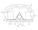
- FIG. 4 is a partial schematic view schematically showing the accommodation state of the diffusion plate 231 and the reflection sheet 29 in the liquid crystal television 100 according to Embodiment 2 of the present invention.
- the diffusing plate 231 has a rectangular shape that follows the bottom 222 of the backlight chassis 22, and there are three backside edge portions on the back side. Cutouts 231a, 231a,..., 231a are formed so as to correspond to the positioning portions 224, 224,. The cutouts 231a, 231a,..., 231a are provided at appropriate positions so as to engage with the positioning portions 224, 224,..., 224 when the diffusion plate 231 is accommodated in the backlight chassis 22. It has been.
- the shape of the recesses by the notches 231a, 231a,..., 231a is formed to be, for example, a triangle in the thickness direction of the diffusion plate 231. Yes.
- the reflection sheet 29 has a plurality of convex portions 29b, 29b,..., 29b extending on the respective long sides as in the first embodiment, and the shape of each convex portion 29b. Is generally rectangular.
- each convex portion 29b is formed with a triangular missing portion 29c that follows the notches 231a, 231a,.
- the missing portions 29 c, 29 c,..., 29 c are formed so that the shape of the recesses is a triangle in the thickness direction of the reflective sheet 29.
- the position of the reflection sheet 29 in the backlight chassis 22 is determined by fitting each of the missing portions 29 c to the positioning portions 224.
- the positions corresponding to the notches 231a, 231a,. , 29c in the convex portions 29b, 29b,..., 29b of the reflection sheet 29 are arranged. Further, a concave portion 292 of the reflection sheet 29 is disposed at a position corresponding to the surplus edge portion 231b of the diffusion plate 231 in the facing direction.
- the light reflectance is increased by the convex portions 29b, 29b,.
- the concave portion 292 of the reflection sheet 29 is disposed at a position corresponding to the surplus edge portion 231b of the diffusion plate 231, and the bottom 222 of the backlight chassis 22 is exposed, so that the light reflectance is lowered.
- unevenness can be prevented from occurring at the end portion on the long side of the diffusion plate 231 and the display quality can be kept good.
- the shape of the recesses by the notches 231a, 231a,..., 231a is formed to be a triangle in the thickness direction of the diffusion plate 231. ing. Therefore, compared with the case where the shape of such a recessed part is a rectangle, the corner part which can become a dark part can be reduced.
- the dark part appears in a shape close to the shape of the cutout of the diffuser plate 231.
- the cutout part 29c the concealment of unevenness due to the dark part due to the cutout is further enhanced. That is, it is possible to avoid a reverse phenomenon in which a local dark part occurs.
- the liquid crystal television 100 is configured such that in the opposing direction of the diffusion plate 231 and the reflection sheet 29, the shape of each projection 29b of the reflection sheet 29 and the shape of the recess formed by each notch 231a of the diffusion plate 231.
- a rectangular shape having substantially the same size is used, and these are arranged so as to be aligned with each other.
- the present invention is not limited to this.
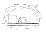
- FIG. 5 is a partial schematic view schematically showing the accommodation state of the diffusion plate 231 and the reflection sheet 29 in the liquid crystal television 100 according to Embodiment 3 of the present invention.
- the diffuser plate 231 corresponds to the positioning portions 224, 224,..., 224 of the backlight chassis 22 at three positions on the long side edges. Notches 231a, 231a,..., 231a are formed so that they can be made. The cutouts 231a, 231a,..., 231a are provided at appropriate positions so as to engage with the positioning portions 224, 224,..., 224 when the diffusion plate 231 is accommodated in the backlight chassis 22. It has been.
- the shape of the recesses by the notches 231a, 231a,..., 231a is formed to be, for example, substantially circular in the thickness direction of the diffusion plate 231. ing.
- the reflection sheet 29 has a plurality of convex portions 29b, 29b,..., 29b extending on the respective long sides as in the first embodiment, and the shape of each convex portion 29b. Is generally rectangular.
- each convex portion 29b is formed with a circular missing portion 29c following the notches 231a, 231a,.
- the missing portions 29 c, 29 c,..., 29 c are formed such that the shape of the recesses is circular in the thickness direction of the reflection sheet 29.
- the position of the reflection sheet 29 in the backlight chassis 22 is determined by fitting each of the missing portions 29 c to the positioning portions 224.
- the positions corresponding to the notches 231a, 231a,. , 29c in the convex portions 29b, 29b,..., 29b of the reflection sheet 29 are arranged. Further, a concave portion 292 of the reflection sheet 29 is disposed at a position corresponding to the surplus edge portion 231b of the diffusion plate 231 in the facing direction.
- the light reflectance is increased by the convex portions 29b, 29b,.
- the concave portion 292 of the reflection sheet 29 is disposed at a position corresponding to the surplus edge portion 231b of the diffusion plate 231, and the bottom 222 of the backlight chassis 22 is exposed, so that the light reflectance is lowered.
- unevenness can be prevented from occurring at the end portion on the long side of the diffusion plate 231 and the display quality can be kept good.
- the shape of the recesses by the notches 231a, 231a,..., 231a is formed to be circular in the thickness direction of the diffusion plate 231. ing. Therefore, compared with the case where the shape of such a recessed part is a rectangle, the corner part which can become a dark part can be eliminated, and workability can be improved and the strength can be increased.
- the circular notches 29c that follow the notches 231a, 231a,. Similar to the second aspect, the concealability of unevenness due to the dark portion due to the notch is further increased.
- the liquid crystal television 100 is configured such that in the opposing direction of the diffusion plate 231 and the reflection sheet 29, the shape of each projection 29b of the reflection sheet 29 and the shape of the recess formed by each notch 231a of the diffusion plate 231.
- a rectangular shape having substantially the same size is used, and these are arranged so as to be aligned with each other.
- the present invention is not limited to this.
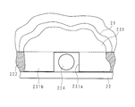
- FIG. 6 is a partial schematic view schematically showing the accommodation state of the diffusion plate 231 and the reflection sheet 29 in the liquid crystal television 100 according to Embodiment 4 of the present invention.
- the diffuser plate 231 corresponds to the positioning portions 224, 224,..., 224 of the backlight chassis 22 at three locations on the long side edge. Notches 231a, 231a,..., 231a are formed so that they can be made. The cutouts 231a, 231a,..., 231a are provided at appropriate positions so as to engage with the positioning portions 224, 224,..., 224 when the diffusion plate 231 is accommodated in the backlight chassis 22. It has been.
- the shape of the recesses by the notches 231a, 231a,..., 231a is formed to be, for example, a rectangle in the thickness direction of the diffusion plate 231. Yes.
- the reflection sheet 29 does not have the convex portion 29b. Therefore, in the liquid crystal television 100 according to Embodiment 4 of the present invention, the bottom 222 of the backlight chassis 22 is exposed at a position corresponding to the surplus edge 231b of the diffusion plate 231 in the facing direction.
- gray or black is thus formed on a portion of the bottom 222 exposed at a position corresponding to the surplus edge 231b of the diffusion plate 231 in the facing direction.
- the paint is printed.
- the gray or black paint is applied at a position corresponding to the surplus edge portion 231b of the diffusion plate 231 in the facing direction of the diffusion plate 231 and the reflection sheet 29. A portion of the bottom 222 printed with the film is exposed.
- the gray or black bottom 222 (film) is exposed at a position corresponding to the surplus edge portion 231b of the diffuser plate 231, thereby lowering the light reflectance in such a portion.
- the concealability of the dark portion in the vicinity of the concave portion due to the notches 231a, 231a,. Can be kept good.
- a gray or black paint film is printed on the part of the bottom 222 as an example, but the present invention is not limited to this.
- a light absorber may be applied as long as the reflectance is reduced.
- the present invention is not limited to the above description. You may comprise so that the said film
- the film has a constant reflection spectral distribution characteristic, it is possible to avoid local coloring. That is, when the reflectance increases, the amount of light in the notches 231a, 231a,.
- the film of the backlight chassis 22 may be formed by printing a plurality of fine dots. In this case, it becomes easy to make the density of printing, coloration of portions other than the notches 231a, 231a,... 231a of the diffusion plate 231 is prevented, and display unevenness is less likely to be visually recognized.
- the diameter of the dots may be configured to become smaller toward the center of the backlight chassis 22. In such a case, the density of printing can be easily adjusted.
- one surface from which light incident from the light source 27 side is emitted toward the optical sheet 232 may be configured to have a lens shape.
- the one surface of the diffusion plate 231 is configured to have a plurality of cylindrical lens shapes. As a result, the unevenness that has entered the display area of the liquid crystal panel 11 that is visually recognized by the user is diffused, so that it is difficult for the user to visually recognize the display unevenness in the display area.
- the present invention is not limited to the above, and the one surface of the diffusion plate 231 may be configured to have diffusion beads.
- the diffusion beads may be, for example, spherical particles having an average particle diameter of 5 to 40 ⁇ m and made of silica, crosslinked polymethyl methacrylate, crosslinked polystyrene, calcium carbonate, or the like. Desirably, the refractive index should be 1.4 to 1.7 and have a sharp particle size distribution.
- the diffusion beads on the one surface of the diffusion plate 231, it is possible to diffuse the unevenness that has entered the display area, and it becomes difficult for the user to visually recognize the display unevenness in the display area.
- the present invention is not limited to the above, and the diffusion plate 231 itself may be configured to include diffusion beads.
- the diffusion beads in this case may be those having an average particle diameter of 500 nm to 100 ⁇ m and made of silica, acrylic, organic-inorganic composite (for example, silica / acryl composite), or the like. Desirably, it is preferably spherical and has a sharp particle size distribution, solvent resistance, heat resistance and light resistance, and a refractive index of 1.4 to 1.7.
- the diffusion effect inside the diffusion plate 231 can be enhanced, and the dark portion unevenness that has entered the diffusion plate 231 can be diffused. It becomes difficult to visually recognize display unevenness.
Landscapes
- Physics & Mathematics (AREA)
- Nonlinear Science (AREA)
- Mathematical Physics (AREA)
- Chemical & Material Sciences (AREA)
- Crystallography & Structural Chemistry (AREA)
- General Physics & Mathematics (AREA)
- Optics & Photonics (AREA)
- Planar Illumination Modules (AREA)
- Liquid Crystal (AREA)
Abstract
Description
図1は本発明の実施の形態1に係る液晶テレビジョンの要部構成を示す分解斜視図であり、図2は本発明の実施の形態1に係る液晶テレビジョンにおいて、拡散板及び反射シートの収容状態を模式的に示す模式図である。図中符号100は、本発明の実施の形態に係る液晶テレビジョンを示す。
実施の形態1においては、液晶テレビジョン100が、拡散板231及び反射シート29の対向方向において、反射シート29の各凸部29bの形状と、拡散板231の各切り欠き231aによる凹部の形状とが共に略等しい大きさの矩形であり、かつ、これらは相互整合するように配置されている場合を例に説明したが、本発明はこれに限るものでない。
実施の形態1においては、液晶テレビジョン100が、拡散板231及び反射シート29の対向方向においては、反射シート29の各凸部29bの形状と、拡散板231の各切り欠き231aによる凹部の形状とは共に略等しい大きさの矩形であり、かつ、これらは相互整合するように配置されている場合を例に説明したが、本発明はこれに限るものでない。
実施の形態1においては、液晶テレビジョン100が、拡散板231及び反射シート29の対向方向においては、反射シート29の各凸部29bの形状と、拡散板231の各切り欠き231aによる凹部の形状とは共に略等しい大きさの矩形であり、かつ、これらは相互整合するように配置されている場合を例に説明したが、本発明はこれに限るものでない。
22 バックライトシャーシ(収容筐体)
27 光源
29 反射シート
29b 凸部
29c 欠落部
100 液晶テレビジョン
222 底
292 凹部
224 位置決め部
231 拡散板
231a 切り欠き
231b 剰余縁部
Claims (15)
- 光源と、該光源からの光を拡散する拡散部材と、前記光源からの光を該拡散部材に反射する反射シートと、前記拡散部材及び反射シートを対向収容する収容筐体と、該収容部に設けられ、前記拡散部材及び反射シートの前記収容筐体内位置を決める位置決め部とを備える光源装置において、
前記拡散部材は前記位置決め部に対応する切り欠きを一側面部に設け、
前記反射シートは前記拡散部材の前記一側面に対応する一縁部に凹凸を有しており、
前記対向の方向にて、前記拡散部材の前記切り欠きは、前記反射シートの前記一縁部の凸部に対応して配置されていることを特徴とする光源装置。 - 前記拡散部材の前記一側面部の前記切り欠きを除く剰余部は、前記対向の方向にて、前記反射シートの前記一縁部の凹部に対応して配置されていることを特徴とする請求項1に記載の光源装置。
- 前記反射シートの前記凸部には、前記対向の方向にて、前記拡散部材の前記切り欠きと対向する位置に、該切り欠きと相似形である欠落部を有することを特徴とする請求項1又は2に記載の光源装置。
- 前記反射シートの前記欠落部は、略三角形であることを特徴とする請求項3に記載の光源装置。
- 前記反射シートの前記欠落部は、略円形であることを特徴とする請求項3に記載の光源装置。
- 前記反射シートの前記凸部は蛍光剤を含むことを特徴とする請求項1から5の何れかに記載の光源装置。
- 前記蛍光剤は一定な反射分光分布特性を有していることを特徴とする請求項6に記載の光源装置。
- 光源と、該光源からの光を拡散する拡散部材と、前記光源からの光を該拡散部材に反射する反射シートと、前記拡散部材及び反射シートを対向収容する収容筐体と、該収容部に設けられ、前記拡散部材及び反射シートの前記収容筐体内位置を決める位置決め部とを備える光源装置において、
前記拡散部材は前記位置決め部に対応する切り欠きを一側面部に設け、
前記拡散部材は、前記対向の方向にて、前記一側面部の前記切り欠きを除く剰余部が、前記収容筐体の底と対面しており、
前記収容筐体の底のうち、前記剰余部と対面する部分には、他部分より低い反射率を有する膜が形成されていることを特徴とする光源装置。 - 前記収容筐体の前記膜は一定な反射分光分布特性を有していることを特徴とする請求項8に記載の光源装置。
- 前記収容筐体の前記膜は複数のドットの印刷により形成されていることを特徴とする請求項8に記載の光源装置。
- 前記ドットの径は前記収容筐体底の中央部に向かうに従い小さくなるように構成されていることを特徴とする請求項10に記載の光源装置。
- 前記拡散部材は光が出射する一面がレンズ形状を有することを特徴とする請求項1から11の何れかに記載の光源装置。
- 前記拡散部材は光が出射する一面が拡散ビーズを有することを特徴とする請求項1から11の何れかに記載の光源装置。
- 前記拡散部材は拡散ビーズを含むことを特徴とする請求項1から13の何れかに記載の光源装置。
- 請求項1から6の何れかに記載の光源装置と、
前記拡散部材の一面側に設けられており、該拡散部材を介して入射される光を用いて画像を表示する表示パネルと
を備えることを特徴とする表示装置。
Priority Applications (4)
| Application Number | Priority Date | Filing Date | Title |
|---|---|---|---|
| JP2015529246A JP6177330B2 (ja) | 2013-07-30 | 2013-07-30 | 光源装置及び表示装置 |
| PCT/JP2013/070532 WO2015015558A1 (ja) | 2013-07-30 | 2013-07-30 | 光源装置及び表示装置 |
| US14/908,445 US9791739B2 (en) | 2013-07-30 | 2013-07-30 | Light source device and display apparatus |
| CN201380078655.4A CN105431674B (zh) | 2013-07-30 | 2013-07-30 | 光源装置和显示装置 |
Applications Claiming Priority (1)
| Application Number | Priority Date | Filing Date | Title |
|---|---|---|---|
| PCT/JP2013/070532 WO2015015558A1 (ja) | 2013-07-30 | 2013-07-30 | 光源装置及び表示装置 |
Publications (1)
| Publication Number | Publication Date |
|---|---|
| WO2015015558A1 true WO2015015558A1 (ja) | 2015-02-05 |
Family
ID=52431140
Family Applications (1)
| Application Number | Title | Priority Date | Filing Date |
|---|---|---|---|
| PCT/JP2013/070532 Ceased WO2015015558A1 (ja) | 2013-07-30 | 2013-07-30 | 光源装置及び表示装置 |
Country Status (4)
| Country | Link |
|---|---|
| US (1) | US9791739B2 (ja) |
| JP (1) | JP6177330B2 (ja) |
| CN (1) | CN105431674B (ja) |
| WO (1) | WO2015015558A1 (ja) |
Cited By (1)
| Publication number | Priority date | Publication date | Assignee | Title |
|---|---|---|---|---|
| US20250102860A1 (en) * | 2023-09-21 | 2025-03-27 | Radiant Opto-Electronics Corporation | Backlight module and display device |
Families Citing this family (2)
| Publication number | Priority date | Publication date | Assignee | Title |
|---|---|---|---|---|
| WO2016068590A1 (en) * | 2014-10-31 | 2016-05-06 | Lg Electronics Inc. | Backlight unit and display device including backlight unit |
| CN112882276A (zh) * | 2021-02-23 | 2021-06-01 | 成都京东方光电科技有限公司 | 背光模组和具有其的显示面板 |
Citations (3)
| Publication number | Priority date | Publication date | Assignee | Title |
|---|---|---|---|---|
| WO2006095552A1 (ja) * | 2005-03-10 | 2006-09-14 | Sharp Kabushiki Kaisha | バックライトユニット及びこれを備えた表示装置 |
| WO2006134735A1 (ja) * | 2005-06-16 | 2006-12-21 | Sharp Kabushiki Kaisha | 光学シート並びにこれを用いたバックライト装置及び表示装置 |
| JP2012004056A (ja) * | 2010-06-21 | 2012-01-05 | Casio Computer Co Ltd | 表示装置 |
Family Cites Families (14)
| Publication number | Priority date | Publication date | Assignee | Title |
|---|---|---|---|---|
| JP2004235103A (ja) * | 2003-01-31 | 2004-08-19 | Sumitomo Rubber Ind Ltd | 直下型バックライト |
| KR101082898B1 (ko) * | 2005-05-25 | 2011-11-11 | 삼성전자주식회사 | 백라이트 어셈블리 및 이를 갖는 액정표시장치 |
| US7632000B2 (en) * | 2005-05-25 | 2009-12-15 | Samsung Electronics Co., Ltd. | Backlight assembly and liquid crystal display device having the same |
| JP2007042613A (ja) * | 2005-07-07 | 2007-02-15 | Matsushita Electric Works Ltd | 液晶パネル用照明装置 |
| US20070086179A1 (en) * | 2005-10-14 | 2007-04-19 | Radiant Opto-Electronics Corporation | Light mixing plate and direct backlight module |
| KR101472141B1 (ko) * | 2008-12-27 | 2014-12-12 | 엘지디스플레이 주식회사 | 액정표시장치 |
| JP2010282856A (ja) * | 2009-06-05 | 2010-12-16 | Funai Electric Co Ltd | 液晶モジュール |
| WO2010146931A1 (ja) * | 2009-06-17 | 2010-12-23 | シャープ株式会社 | 表示装置、テレビ受信装置 |
| KR20110000175A (ko) * | 2009-06-26 | 2011-01-03 | 삼성전자주식회사 | 백라이트 장치, 도광판 및 이를 적용한 디스플레이 장치 |
| JP5303657B2 (ja) * | 2009-12-28 | 2013-10-02 | シャープ株式会社 | 照明装置、表示装置、及びテレビ受信装置 |
| JP2012084303A (ja) | 2010-10-08 | 2012-04-26 | Sharp Corp | 光源モジュールおよび電子機器 |
| JP2013026110A (ja) * | 2011-07-25 | 2013-02-04 | Seiko Epson Corp | 照明装置、液晶表示装置および電子機器 |
| CN103104891A (zh) * | 2011-11-15 | 2013-05-15 | 苏州璨宇光学有限公司 | 光学膜片限位结构 |
| TWI438535B (zh) * | 2011-11-18 | 2014-05-21 | Au Optronics Corp | 光學膜片組及應用此光學膜片組的背光模組 |
-
2013
- 2013-07-30 US US14/908,445 patent/US9791739B2/en not_active Expired - Fee Related
- 2013-07-30 CN CN201380078655.4A patent/CN105431674B/zh not_active Expired - Fee Related
- 2013-07-30 WO PCT/JP2013/070532 patent/WO2015015558A1/ja not_active Ceased
- 2013-07-30 JP JP2015529246A patent/JP6177330B2/ja not_active Expired - Fee Related
Patent Citations (3)
| Publication number | Priority date | Publication date | Assignee | Title |
|---|---|---|---|---|
| WO2006095552A1 (ja) * | 2005-03-10 | 2006-09-14 | Sharp Kabushiki Kaisha | バックライトユニット及びこれを備えた表示装置 |
| WO2006134735A1 (ja) * | 2005-06-16 | 2006-12-21 | Sharp Kabushiki Kaisha | 光学シート並びにこれを用いたバックライト装置及び表示装置 |
| JP2012004056A (ja) * | 2010-06-21 | 2012-01-05 | Casio Computer Co Ltd | 表示装置 |
Cited By (2)
| Publication number | Priority date | Publication date | Assignee | Title |
|---|---|---|---|---|
| US20250102860A1 (en) * | 2023-09-21 | 2025-03-27 | Radiant Opto-Electronics Corporation | Backlight module and display device |
| US12510782B2 (en) * | 2023-09-21 | 2025-12-30 | Radiant Opto-Electronics Corporation | Backlight module and display device |
Also Published As
| Publication number | Publication date |
|---|---|
| US9791739B2 (en) | 2017-10-17 |
| JPWO2015015558A1 (ja) | 2017-03-02 |
| CN105431674B (zh) | 2017-07-14 |
| US20160170266A1 (en) | 2016-06-16 |
| CN105431674A (zh) | 2016-03-23 |
| JP6177330B2 (ja) | 2017-08-09 |
Similar Documents
| Publication | Publication Date | Title |
|---|---|---|
| JP5154695B2 (ja) | 照明装置、表示装置、及びテレビ受信装置 | |
| KR102395088B1 (ko) | 백라이트 유닛 및 이를 포함하는 액정 표시 장치 | |
| US9588273B2 (en) | Optical pattern sheet, backlight unit, and liquid crystal display having the same | |
| US20150253484A1 (en) | Illumination device and display device | |
| KR101818252B1 (ko) | 백라이트 유닛 및 이를 포함하는 액정표시장치 | |
| US9016919B2 (en) | Lighting device, display device and television receiver | |
| WO2011077866A1 (ja) | 照明装置、表示装置、及びテレビ受信装置 | |
| JP5138813B2 (ja) | 照明装置、表示装置、及びテレビ受信装置 | |
| KR20140106905A (ko) | 액정표시장치 | |
| KR102222297B1 (ko) | 균일한 휘도가 가능한 반사판 및 이를 구비한 액정표시소자 | |
| CN104321584A (zh) | 光源装置以及显示装置 | |
| KR102090457B1 (ko) | 액정표시장치 | |
| WO2011111444A1 (ja) | 照明装置、表示装置、及びテレビ受信装置 | |
| WO2011148694A1 (ja) | 照明装置、表示装置、及びテレビ受信装置 | |
| WO2011152134A1 (ja) | 照明装置、表示装置及びテレビ受信装置 | |
| WO2014021303A1 (ja) | 照明装置、表示装置、及びテレビ受信装置 | |
| JP6177330B2 (ja) | 光源装置及び表示装置 | |
| WO2011077864A1 (ja) | 照明装置、表示装置、及びテレビ受信装置 | |
| KR20120075135A (ko) | 차광테이프와 이를 적용한 백라이트 유닛 및 이를 구비한 액정표시장치 | |
| KR20120075134A (ko) | 백라이트 유닛 및 이를 구비한 액정표시장치 | |
| KR20180046937A (ko) | 일체형 확산판 및 이를 이용한 백 라이트 유닛과 액정 표시장치 | |
| WO2017104081A1 (ja) | 表示装置 | |
| JP2013178907A (ja) | 照明装置、表示装置、及びテレビ受信装置 | |
| KR20130037293A (ko) | 백라이트 유닛 및 이를 이용한 액정디스플레이 모듈 | |
| WO2013047374A1 (ja) | 照明装置、表示装置及びテレビ受信装置 |
Legal Events
| Date | Code | Title | Description |
|---|---|---|---|
| WWE | Wipo information: entry into national phase |
Ref document number: 201380078655.4 Country of ref document: CN |
|
| 121 | Ep: the epo has been informed by wipo that ep was designated in this application |
Ref document number: 13890733 Country of ref document: EP Kind code of ref document: A1 |
|
| WWE | Wipo information: entry into national phase |
Ref document number: 14908445 Country of ref document: US |
|
| ENP | Entry into the national phase |
Ref document number: 2015529246 Country of ref document: JP Kind code of ref document: A |
|
| NENP | Non-entry into the national phase |
Ref country code: DE |
|
| 122 | Ep: pct application non-entry in european phase |
Ref document number: 13890733 Country of ref document: EP Kind code of ref document: A1 |