WO2015012355A1 - 眼内レンズの挿入器具 - Google Patents
眼内レンズの挿入器具 Download PDFInfo
- Publication number
- WO2015012355A1 WO2015012355A1 PCT/JP2014/069573 JP2014069573W WO2015012355A1 WO 2015012355 A1 WO2015012355 A1 WO 2015012355A1 JP 2014069573 W JP2014069573 W JP 2014069573W WO 2015012355 A1 WO2015012355 A1 WO 2015012355A1
- Authority
- WO
- WIPO (PCT)
- Prior art keywords
- intraocular lens
- tip
- nozzle body
- distal end
- opening
- Prior art date
Links
Images


Classifications
-
- A—HUMAN NECESSITIES
- A61—MEDICAL OR VETERINARY SCIENCE; HYGIENE
- A61F—FILTERS IMPLANTABLE INTO BLOOD VESSELS; PROSTHESES; DEVICES PROVIDING PATENCY TO, OR PREVENTING COLLAPSING OF, TUBULAR STRUCTURES OF THE BODY, e.g. STENTS; ORTHOPAEDIC, NURSING OR CONTRACEPTIVE DEVICES; FOMENTATION; TREATMENT OR PROTECTION OF EYES OR EARS; BANDAGES, DRESSINGS OR ABSORBENT PADS; FIRST-AID KITS
- A61F2/00—Filters implantable into blood vessels; Prostheses, i.e. artificial substitutes or replacements for parts of the body; Appliances for connecting them with the body; Devices providing patency to, or preventing collapsing of, tubular structures of the body, e.g. stents
- A61F2/02—Prostheses implantable into the body
- A61F2/14—Eye parts, e.g. lenses, corneal implants; Implanting instruments specially adapted therefor; Artificial eyes
- A61F2/16—Intraocular lenses
- A61F2/1662—Instruments for inserting intraocular lenses into the eye
- A61F2/167—Instruments for inserting intraocular lenses into the eye with pushable plungers
-
- A—HUMAN NECESSITIES
- A61—MEDICAL OR VETERINARY SCIENCE; HYGIENE
- A61F—FILTERS IMPLANTABLE INTO BLOOD VESSELS; PROSTHESES; DEVICES PROVIDING PATENCY TO, OR PREVENTING COLLAPSING OF, TUBULAR STRUCTURES OF THE BODY, e.g. STENTS; ORTHOPAEDIC, NURSING OR CONTRACEPTIVE DEVICES; FOMENTATION; TREATMENT OR PROTECTION OF EYES OR EARS; BANDAGES, DRESSINGS OR ABSORBENT PADS; FIRST-AID KITS
- A61F2/00—Filters implantable into blood vessels; Prostheses, i.e. artificial substitutes or replacements for parts of the body; Appliances for connecting them with the body; Devices providing patency to, or preventing collapsing of, tubular structures of the body, e.g. stents
- A61F2/02—Prostheses implantable into the body
- A61F2/14—Eye parts, e.g. lenses, corneal implants; Implanting instruments specially adapted therefor; Artificial eyes
- A61F2/16—Intraocular lenses
- A61F2/1662—Instruments for inserting intraocular lenses into the eye
- A61F2/1678—Instruments for inserting intraocular lenses into the eye with a separate cartridge or other lens setting part for storage of a lens, e.g. preloadable for shipping
Definitions
- the present invention relates to an intraocular lens insertion device.
- intraocular lenses that are inserted as a substitute for the lens for the replacement of the human turbid lens and the correction of refraction in the treatment of cataract have been put to practical use.
- intraocular lens insertion surgery for cataract treatment for example, an incision (incision) of several millimeters is provided at the edge of the cornea, and the lens is crushed and removed from the incision by ultrasonic phacoemulsification. The inner lens is inserted and fixed.
- the material of the intraocular lens PMMA (polymethyl methacrylate), acrylic resin, silicon resin, or the like is used.
- the structure of the intraocular lens is mainly divided into an optical part and a support part that holds the optical part.
- the intraocular lens is enclosed in a dedicated intraocular lens insertion device, and the intraocular lens insertion device is aseptically removed from the package etc. during use, and the tip of the insertion device is inserted into the eye through the incision.
- the instrument is operated to guide the intraocular lens into the capsular bag.
- the insertion instrument is configured to be released from the distal end of the insertion instrument into the eye with the intraocular lens bent.
- patent document 1 it is comprised so that the opening part of the insertion instrument front-end
- a canopy is provided at the tip of the opening. The canopy functions to open the incision when the insertion instrument tip is inserted into the incision.
- patent document 2 it is comprised so that the end surface of the opening part of an insertion instrument front-end
- the intraocular lens when trying to insert the distal end of the insertion instrument into a smaller incision, it may be difficult to completely insert the opening to a predetermined position in the incision with the opening having the shape disclosed in the above document. .
- the intraocular lens if the intraocular lens is pushed into the lens capsule without completely inserting the opening into the incision, the intraocular lens protrudes from a part of the opening located outside the incision so that the eye is normally There is a possibility that the inner lens cannot be inserted.
- the technology disclosed herein has been made in view of the above circumstances, and its purpose is to prevent the intraocular lens from being ejected outside the eye when inserted into a smaller incision than in the prior art. It is to realize an insertion device that can be guided into the eye while being held stably.
- the intraocular lens insertion device of the present disclosure includes a substantially cylindrical main body portion that accommodates the intraocular lens, a front end opening provided at the front end of the main body, and a substantially flat plate shape provided at the front end of the front end opening.
- a pair of projections that are substantially parallel to each other across the central axis on the distal end side of the distal end opening.
- a tip region having a side wall is provided.
- the intraocular lens insertion device of the present disclosure includes a proximal end region connected to the rear end of the distal end region on the rear end side of the distal end opening, and is orthogonal to the central axis of the inclined surface in the distal end region.
- the inclination angle with respect to the surface is smaller than the inclination angle with respect to the surface orthogonal to the central axis of the inclined surface in the proximal region.
- the contour line that appears in a lateral view has a bending point between the distal end region and the proximal end region at the distal end opening.
- the side wall of the tip region is formed so as to rise sharply, and the intraocular lens can be more stably held in the tip region. For this reason, when the intraocular lens is guided into the lens capsule, a phenomenon in which the intraocular lens is emitted from the distal end opening to the outside of the eye can be suppressed.
- the intraocular lens insertion device of this indication is a taper shape where the outer periphery shape of a front-end
- the main body further includes an intraocular lens positioning member, and the intraocular lens is previously positioned by the positioning member.
- an insertion device that can guide an intraocular lens into the eye while being stably held while preventing the eye from being ejected outside the eye when inserted into a narrower incision than in the past. Can be realized.
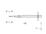
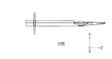
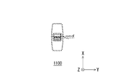
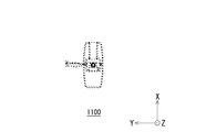
- FIG. 1 (a) and FIG.1 (b) are figures which show schematic structure of the insertion instrument of the intraocular lens in one Embodiment.
- FIG. 2A and FIG. 2B are diagrams illustrating a schematic configuration of an intraocular lens according to an embodiment.
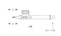
- FIG. 3 is a diagram illustrating a schematic configuration of a nozzle body of an intraocular lens insertion device according to an embodiment.
- FIG. 4 is a diagram illustrating a schematic configuration of a positioning member of an intraocular lens insertion device according to an embodiment.
- FIG. 5A and FIG. 5B are diagrams showing a schematic configuration of a plunger of an intraocular lens in one embodiment.
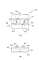
- FIG. 6 is a detailed plan view of the vicinity of the distal end of the intraocular lens insertion device according to one embodiment.
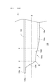
- FIG. 7 is a detailed side view of the vicinity of the distal end of the intraocular lens insertion device according to one embodiment.
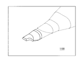
- FIG. 8 is a perspective view of the vicinity of the distal end of the intraocular lens insertion device according to one embodiment.
- FIGS. 9A to 9C are cross-sectional views of an insertion tube portion of an intraocular lens insertion device according to an embodiment.
- FIG. 10A is a perspective view of a nozzle body of an insertion device according to a modification.
- FIG. 10B is a perspective view of a nozzle body of an insertion device according to a modification.
- FIG. 10A is a perspective view of a nozzle body of an insertion device according to a modification.
- FIG. 10C is a perspective view of a nozzle body of an insertion device according to a modification.
- FIG. 10D is a diagram showing a nozzle body of an insertion instrument according to a modification.
- FIG. 10E is a view showing a nozzle body of an insertion instrument according to a modification.
- FIG. 10F is a diagram illustrating a nozzle body of an insertion instrument according to a modification.
- FIG. 10G is a view showing a nozzle body of an insertion instrument according to a modification.
- FIG. 10H is a view showing a nozzle body of an insertion instrument according to a modification.
- FIG. 10I is a diagram showing a nozzle body of an insertion instrument according to a modification.
- FIG. 10J is a partially enlarged view of the nozzle body of the insertion device according to the modification.
- FIG. 10K is a partially enlarged view of a nozzle body of an insertion instrument according to a modification.
- FIG. 10L is a partially enlarged view of a nozzle body of an insertion device according to a modification.
- FIG. 10M is a partially enlarged view of a nozzle body of an insertion device according to a modification.
- FIG. 10N is a partially enlarged view of the nozzle body of the insertion device according to the modification.
- FIG. 10P is a cross-sectional view of a nozzle body of an insertion device according to a modification.
- FIG. 11A is a perspective view of a nozzle body of an insertion device according to a modification.
- FIG. 11A is a perspective view of a nozzle body of an insertion device according to a modification.
- FIG. 11A is a perspective view of a nozzle body of an insertion device according
- FIG. 11B is a perspective view of a nozzle body of an insertion device according to a modification.
- FIG. 11C is a perspective view of a nozzle body of an insertion device according to a modification.
- FIG. 11D is a diagram showing a nozzle body of an insertion instrument according to a modification.
- FIG. 11E is a view showing a nozzle body of an insertion instrument according to a modification.
- FIG. 11F is a diagram illustrating a nozzle body of an insertion instrument according to a modification.
- FIG. 11G is a diagram showing a nozzle body of an insertion instrument according to a modification.
- FIG. 11H is a diagram illustrating a nozzle body of an insertion instrument according to a modification.
- FIG. 11I is a diagram illustrating a nozzle body of an insertion instrument according to a modification.
- FIG. 11J is a partially enlarged view of the nozzle body of the insertion instrument according to the modification.
- FIG. 11K is a partially enlarged view of a nozzle body of an insertion instrument according to a modification.
- FIG. 11L is a partially enlarged view of a nozzle body of an insertion instrument according to a modification.
- FIG. 11M is a partially enlarged view of a nozzle body of an insertion device according to a modification.
- FIG. 11N is a partially enlarged view of a nozzle body of an insertion device according to a modification.
- FIG. 11P is a cross-sectional view of a nozzle body of an insertion device according to a modification.
- an intraocular lens insertion device according to an embodiment will be described with reference to the drawings.
- this embodiment shows an example of an intraocular lens insertion device, and is not limited to the configuration described below.
- the intraocular lens insertion device 1 includes a nozzle body 100, a stage unit 200, and a plunger 300.
- the nozzle body 100 has a long, generally cylindrical shape that is penetrated through its entire length.
- the nozzle body 100 corresponds to an example of a body part.
- the cross section of the nozzle body 100 in a plane perpendicular to the longitudinal direction is substantially rectangular.
- the intraocular lens 2 is housed inside the nozzle body 100, and the intraocular lens 2 is held on the nozzle body 100 by the stage unit 200.
- the plunger 300 is a rod-shaped member having a long cylindrical shape. Part of the plunger 300 is inserted through the cylindrical portion of the nozzle body 100.
- the plunger 300 is used as an extrusion member for guiding the intraocular lens 300 into the capsular bag during treatment.
- the Z axis is set so that the direction from the rear end 100b of the nozzle body 100 toward the front end 100a is positive in parallel to the longitudinal direction of the insertion instrument 1. Then, an X axis and a Y axis perpendicular to the Z axis and orthogonal to each other are set. As described below, the X axis coincides with the optical axis of the intraocular lens 2 positioned by the positioning member 210 in the nozzle body 100. The Z axis coincides with the pushing direction of the plunger 300 inserted into the nozzle body 100.
- a surface provided on the negative side of the X axis may be referred to as a bottom surface, and a surface provided on the positive side of the X axis may be referred to as an upper surface.
- the positive side of the X axis may be referred to as the upper side, the negative side of the X axis as the lower side, the positive side of the Z axis as the front, and the negative side of the Z axis as the rear.
- a plate-like holding unit 110 that protrudes from the nozzle body 100 in the XY axis direction is provided.
- the user pushes the plunger 300 toward the tip 100 a side of the nozzle body 100, the user places his / her finger on the holding unit 110.
- a locking hole 120 is provided on the rear end 100 b side with respect to the hold portion 110. The locking hole 120 is used as a holding unit that holds the plunger 300 in the nozzle body 100.
- a stage unit 200 is provided near the tip 100a of the nozzle body 100.
- the stage unit 200 includes a positioning member 210 and a stage lid unit 220.
- the positioning member 210 is a member for stably holding the intraocular lens 2 on the stage unit 200 before using the insertion instrument 1 or during transportation.
- the intraocular lens 2 is set on the stage unit 200 in a state where the stage lid unit 220 is opened and the positioning member 210 is attached to the stage unit 200 at the time of manufacture. Then, the user removes the positioning member 210 while the stage lid portion 220 of the insertion instrument 1 is closed.
- the user pushes the intraocular lens 2 from the insertion tube part 130 while pressing the intraocular lens 2 by the plunger 300 by pushing the plunger 300 toward the tip 100 a side of the nozzle body 100.
- the raw material of the nozzle main body 100, the stage part 200, and the plunger 300 of the insertion instrument 1 is formed with resin, such as a polypropylene.
- Polypropylene is a material that has a proven track record in medical equipment, has good biocompatibility, and has high reliability such as chemical resistance.
- FIG. 2A and 2 (b) are diagrams showing a schematic configuration of the intraocular lens 2.
- FIG. 2A is a plan view of the intraocular lens 2
- FIG. 2B is a side view thereof.
- the intraocular lens 2 includes an optical unit 2a having a predetermined power and a support unit 2b provided on the optical unit 2a.
- the support part 2b is a member for holding the optical part 2a in the eyeball.
- the optical part 2a and the support part 2b are formed of a flexible resin material.
- FIG. 3 shows a plan view of the nozzle body 100.
- the intraocular lens 2 is set on the stage unit 200 of the nozzle body 100.
- the intraocular lens 2 is pressed by the plunger 300 and pushed out from the insertion tube portion 130.
- the nozzle body 100 is provided with a through hole 100c whose cross-sectional shape changes according to a change in the outer shape of the nozzle body 100.
- the intraocular lens 2 is pushed out, the intraocular lens 2 is deformed in accordance with a change in the cross-sectional shape of the through hole 100c in the nozzle body 100, and easily enters an incision formed in the patient's eyeball. Extruded after being transformed into
- a stage groove 200 a having a width slightly larger than the diameter of the optical part 2 a of the intraocular lens 2 is formed in the stage part 200.
- the dimension of the stage groove 200a in the Z-axis direction is set larger than the total length of the intraocular lens 2 including the two support portions 2b extending on both sides of the intraocular lens 2.
- a set surface 200b is formed by the bottom surface of the stage groove 200a.
- the position of the set surface 200b in the X-axis direction is set on the positive side of the X-axis with respect to the position of the bottom surface of the through hole 100c of the nozzle body 100 in the X-axis direction.
- the bottom surface of the through hole 100c refers to a surface parallel to the YZ plane provided on the negative side in the X-axis direction of the inner surface of the through hole 100c in FIG.
- the bottom surface has the same meaning.
- the set surface 200b and the bottom surface of the through hole 100c are connected by a bottom slope 100d.
- the stage part 200 and the stage cover part 220 are integrally formed.
- the dimension of the stage lid part 220 in the Z-axis direction is the same as that of the stage part 200.
- the stage lid portion 220 is connected by a thin plate-like connecting portion 230 formed by extending the side surface of the stage portion 200 to the stage lid portion 220 side.
- the connecting portion 230 is formed to be bendable in the center, and the stage lid portion 220 can be closed by overlapping the stage portion 200 from the positive side of the X axis by bending the connecting portion 230.
- stage lid portion 220 In the stage lid portion 220, ribs 220a and 220b for reinforcing the stage lid portion 220 and stabilizing the position of the intraocular lens 2 are provided on the surface facing the set surface 200b when the lid is closed. Further, a guide protrusion 220 c is provided as a guide when the plunger 300 is pushed forward toward the tip 100 a side of the nozzle body 100.
- a positioning member 210 is detachably provided below the set surface 220b of the stage unit 200, that is, on the negative side of the X axis.
- 4A and 4B show a schematic configuration of the positioning member 210.
- FIG. 4A is a plan view of the positioning member 210
- FIG. 4B is a side view thereof.
- the positioning member 210 is configured as a separate body from the nozzle body 100, and a pair of side wall portions 211 are connected by a connecting portion 212.
- a holding portion 213 that extends outward and extends outward is formed at the lower end of each side wall portion 211.
- a pair of first mounting portions 214 are formed on the upper end portions of the respective side wall portions 211.
- the pair of first mounting portions 214 are formed in an arc shape when viewed from above and project upward.
- a first positioning portion 215 is formed to protrude from the outer peripheral side of the upper end surface of the first placement portion 214. The distance between the inner diameters of the first positioning portions 215 is set to be slightly larger than the optical portion diameter of the optical portion 2 a of the intraocular lens 2.
- a pair of second mounting portions 216 that are rectangular when viewed from above and project upward are formed at both ends in the front-rear direction of the connecting portion 212.
- the height of the upper surface of the second placement unit 216 is equal to the height of the upper end surface of the first placement unit 214.
- a second positioning portion 217 that protrudes further upward is formed on the outer portion of the upper surface of the second placement portion 216 over the entire left and right direction of the second placement portion 216.
- the distance between the second positioning portions 217 is set to be slightly larger than the diameter of the optical portion 2a of the intraocular lens 2.
- a locking claw 218 that slightly protrudes in the front-rear direction is formed on the upper end portion of the second placement portion 216 over the entire left-right direction.
- the positioning member 210 is assembled from the lower side of the set surface 200b of the nozzle body 100, that is, from the negative side of the X axis.
- the set surface 200b of the nozzle body 100 is formed with four set surface through holes 200c penetrating the set surface 200b in the thickness direction.
- the outer shape of the set surface through-hole 200c is a substantially similar shape slightly larger than the shape of the first mounting portion 214 and the second mounting portion 216 of the positioning member 210 viewed from the upper side, that is, the positive side of the X axis. Yes.
- the positioning member 210 is attached to the nozzle body 100, the first placement portion 214 and the second placement portion 216 are inserted into the set surface through hole 200c from the lower side of the set surface 200b, and the set surface 200b. Protrudes above.
- a locking claw 218 provided on the second mounting portion 216 protrudes to the set surface 200b through the set surface through hole 200c and is locked to the upper surface of the set surface 200b. Accordingly, the positioning member 210 is assembled from the lower side of the nozzle body 100, and the first placement portion 214 and the second placement portion 216 are fixed in a state of protruding from the set surface 200b.
- the bottom surface of the outer periphery of the optical unit 2a is placed on the upper surfaces of the first placement unit 214 and the second placement unit 216.
- the position of the optical unit 2a is restricted with respect to the Z-axis direction by the first positioning unit 215 and the second positioning unit 217.
- FIG. 5 shows a schematic configuration of the plunger 300.
- the length of the plunger 300 in the Z-axis direction is slightly larger than that of the nozzle body 100.
- the plunger 300 includes an action portion 310 on the front end side based on a columnar shape, that is, a positive side in the Z-axis direction, and a rear end side based on a rectangular rod shape, ie, a negative side insertion portion 320 in the Z-axis direction. And have.
- the action part 310 includes a columnar part 310a formed in a columnar shape and a thin plate-like flat part 310b extending from the columnar part 310a in the Y-axis direction.
- a notch 310 c is formed at the tip of the action part 310.
- the notch 310c is formed in a groove shape that opens on the positive side of the X axis and penetrates in the Y axis direction.
- the end surface on the front end side of the cutout portion 310c is formed as an inclined surface that approaches the positive side of the X-axis as it approaches the front end side of the action portion 310.
- the insertion part 320 has a substantially H-shaped cross section as a whole, and the dimensions in the X-axis direction and the Y-axis direction are set slightly smaller than the through hole 100c of the nozzle body 100. . Further, a disc-shaped pressing plate portion 330 that extends on the XY plane is formed at the rear end of the insertion portion 320.
- a claw portion 320a that protrudes toward the positive side of the X-axis and is movable in the X-axis direction due to the elasticity of the material of the plunger 300 is formed at the tip side of the insertion portion 320 from the center in the Z-axis direction.
- the claw portion 320a and the locking hole 120a are formed at the positions where the distal end of the action portion 310 is positioned behind the optical portion 2a of the intraocular lens 2 set on the stage portion 200 in the engaged state. It is set to be a place where the notch 310c can support the support part 2b on the rear side of 2a from below.
- the plunger 300 Prior to use of the insertion instrument 1 configured as described above, the plunger 300 is inserted into the nozzle body 100 and disposed at the initial position. Further, as described above, the positioning member 210 is attached to the stage unit 200 from below the set surface 200b. Thereby, the 1st mounting part 214 and the 2nd mounting part 216 of the positioning member 210 are hold
- the intraocular lens 2 is placed and positioned on the first placement portion 214 and the second placement portion 216 in a state where the support portion 2b is arranged in the Z-axis direction of the nozzle body 100 with respect to the optical portion 2a. Is done. In this state, since the outer peripheral part of the optical part 2a is in contact with the first placement part 214 and the second placement part 216, the central part of the intraocular lens 2 is supported in an unloaded state. In this state, the support portion 2 b of the intraocular lens 2 is supported by the bottom surface of the notch portion 310 c of the plunger 300.
- the second mounting portion 216 constitutes a stopper that prevents the plunger 300 from entering the tip 100a of the nozzle body 100.
- the plunger 300 is in a state where it cannot enter unless the positioning member 210 is removed from the nozzle body 100.
- the positioning member 210 is removed from the nozzle body 100.
- the first placement portion 214 and the second placement portion 216 supporting the optical portion 2a of the intraocular lens 2 are retracted from the set surface 200b, and the intraocular lens 2 is placed on the set surface 200b.
- the set surface 200b is a flat surface, the intraocular lens 2 can be stably placed.
- the width dimension of the stage groove 200a is slightly larger than the diameter dimension of the optical part 2a of the intraocular lens 2, rotation of the intraocular lens 2 in the circumferential direction on the set surface 200b is also suppressed. be able to.
- the insertion tube portion 130 of the nozzle body 100 is inserted into the incision provided in the eye tissue.
- the press board part 330 of the plunger 300 is pushed in the front-end
- the distal end of the action part 310 of the plunger 300 comes into contact with the outer periphery of the optical part 2a of the intraocular lens 2 placed on the set surface 200a, and the intraocular lens 2 is guided toward the insertion tube part 130 by the plunger 300.
- FIG. 6 shows a detailed plan view of the vicinity of the insertion tube portion 130 of the nozzle body 100.
- the outer shape of the nozzle body 100 as a whole has a tapered shape that gradually tapers from the stage portion 200 side toward the tip end 100a side.
- the through hole 100c is formed with a reduced diameter portion 100f having a gradually reduced cross-sectional area.
- the reduced diameter portion 100f is configured such that the width dimension of the bottom surface and the top surface becomes smaller toward the tip 100a side, and thereby the cross-sectional area becomes smaller.
- the thickness of the wall surface of the reduced diameter portion 100f is set to a thickness that does not cause valley breakage when the insertion tool 1 is used.
- an inclined surface 100g is formed on the bottom surface of the rear end portion of the reduced diameter portion 100f so as to be inclined to the positive side of the X axis as it goes to the tip 100a side, and a step is formed by the inclined surface 100g. Is provided.
- a pair of introduction protrusions 100h extending in the Z-axis direction of the nozzle body 100 is formed on the bottom surface with the center therebetween.
- the introduction protrusion 100h is provided from the front to the rear of the inclined surface 100g, and is formed in a linear shape that protrudes slightly upward from the bottom surface on the rear end side of the reduced diameter portion 100f and extends parallel to each other.
- the front end portion of the introduction protrusion 100h formed on the inclined surface 100g gradually becomes higher as the inclined surface 100g moves toward the tip 100a, so that the front end portion of the introduction protrusion 100h has the same height at the front end portion of the inclined surface 100g. Is formed.
- the separation distance between the introduction protrusions 100 h is set to be slightly larger than the width of the action part 310 of the plunger 300.
- the through-hole 100c is formed so that it may extend substantially linearly with a substantially constant cross-sectional area. Furthermore, the through-hole 100c is opened in the insertion cylinder part 130, and the front-end
- the protrusion 130c is a member that extends in the push-out direction of the plunger 300 in the nozzle body 100, that is, in the movement direction of the intraocular lens 2 (Z-axis direction in the drawing).
- the tip opening 130a is formed by cutting the insertion tube part 130 obliquely so as to go to the negative side of the Z axis as going to the negative side of the X axis. That is, in the insertion cylinder part 130, the upper end side is extended forward from the lower end side. Further, as shown in FIG. 7, the tip opening 130a is configured to have a bending point G at which the curvature of the contour line changes greatly in a side view. In the distal end opening portion 130a, the distal end 100a side from the bending point is defined as the distal end region 130b, and the rear end 100b side from the bending point is defined as the proximal end region 130d.
- a central axis O is provided in a direction parallel to the Z axis of the nozzle body 100.
- the distal end opening 130a has a distal end region 130b and a proximal end region 130d.
- tip opening part 130a becomes an inclined surface inclined with respect to the plane orthogonal to the central axis O.
- the inclination angle with respect to the plane orthogonal to the central axis O of the inclined surface in the distal end region 130b is set smaller than the inclination angle with respect to the plane orthogonal to the central axis O of the inclined surface in the proximal end region 130d.
- the side wall of the tip region 130b is formed so as to rise steeply in the X-axis direction when the tip opening 130a is viewed from the side.
- the proximal end region 130d is connected to the body portion 130e while gradually increasing the height of the side wall of the distal end region 130b in the X-axis direction.
- the side wall of the distal end region 130 b is a member that extends in the optical axis direction (X-axis direction in the drawing) of the intraocular lens 2 positioned on the stage unit 210.
- the extending direction (X-axis direction in the drawing) of the side wall of the tip region 130b is the pushing direction of the plunger 300, the moving direction of the intraocular lens 2 and the extending direction of the protrusion 130c (shown in the drawing). , Z-axis direction).
- the outer peripheral shape of the tip opening 130a is a tapered shape that tapers toward the tip 100a.
- the outer peripheral shape of the distal end region 130b of the distal end opening 130a is not tapered, but extends from the proximal end region 130d of the distal end opening 130a to the distal end region 130b. It is also possible to configure the outer peripheral shape to be a tapered shape over the entire length. By configuring the tip opening portion 130a to have such a tapered shape, the tip opening portion 130a can be easily inserted into an incision having a smaller width than the conventional one.
- the nozzle body 100 has a tapered portion 100i that tapers toward the tip 100a.
- the tip opening portion 130a opens on the negative side of the X axis.
- the insertion tube portion 130 has a body portion 130e, a proximal end region 130d, a distal end region 130b, and a protruding portion 130c in this order from the rear end 100b of the nozzle body 100 toward the distal end 100a. .
- FIG. 1 For convenience, as shown in FIG.
- the portion of the insertion tube portion 130 on the side of the rear end 100b from the plane F is the body portion 130e and the plane E and the plane E
- a portion between F is a base end region 130d
- a portion between the plane D and the plane E is a tip region 130e
- a portion on the tip 100a side from the plane D is a protrusion 130c.
- the trunk portion 130e has a hollow cylindrical shape. As shown in FIG. 7, the thickness of the bottom surface side of the trunk portion 130e is gradually reduced toward the distal end 100a side. And in the position of the plane F, the trunk
- the proximal end region 130d has a reduced diameter so that the cross-sectional area in the XY plane becomes smaller toward the distal end 100a side, and the outer peripheral shape is a tapered shape. Further, as shown in FIGS. 7 and 8, the height of the side wall in the X-axis direction of the proximal end region 130d is configured to gradually decrease. For this reason, the outer periphery of the proximal end region 130d can be smoothly connected to both the trunk portion 130e and the distal end region 130b.
- the tip region 130b has an upper surface substantially parallel to the YZ plane and a side wall substantially orthogonal to the upper surface and substantially parallel to the XZ plane.
- the upper surface of the tip region 130b is connected to the protrusion 130c on the tip 100a side.
- the height in the X-axis direction of the side wall of the tip region 130b rapidly rises from the position of the plane D to the position of the plane E.
- the protrusion 130c is a flat plate-like member that is formed so that the upper surface of the tip region 130b protrudes toward the tip 100a, and is substantially parallel to the YZ plane.
- FIG. 9 shows cross-sectional views of the nozzle body 100 at three locations on the insertion tube portion 130.
- FIG. 9A shows the AA cross section shown in FIG. 6,
- FIG. 9B shows the BB cross section,
- FIG. 9C shows the CC cross section.
- 9 (a) to 9 (c) when the insertion tube portion 130 is viewed from the negative side of the Z axis to the positive side, that is, when viewed from the rear end 100b side of the nozzle body 100 to the front end 100a side.
- the cross section of is shown.
- the tip region 130b provided on the tip side of the tip opening 130a has a pair of side walls substantially parallel to the XZ plane and a top surface substantially parallel to the YZ plane. It arrange
- the proximal end region 130d has a shape in which the flat side wall of the distal end region 130b is changed to a curved side wall in its cross section.
- the trunk portion 130 e has a lower surface that forms a pair with the upper surface across the central axis O in addition to the upper surface and the side wall of the base region 130 d in the cross section. An upper surface, a lower surface, and a pair of side walls surround the through hole 100c.
- the intraocular lens 2 passes through the tapered portion 100i and then passes through the body portion 130e of the insertion tube portion 130 by the pushing operation of the plunger 300, and the distal end opening portion 130a. Move to. Further, the intraocular lens 2 moves to the proximal end region 130d, moves to the distal end region 130b while maintaining a curved state, and moves into the lens capsule while being held on the side wall of the distal end region 130b. Therefore, when guiding the intraocular lens 2 into the lens capsule, it is possible to prevent the intraocular lens 2 from being ejected outside the eye when the intraocular lens 2 moves to the distal end opening 130a.
- the protrusion 130c at the tip of the insertion tube portion 130, the insertion property of the insertion tube portion 130 into the eyeball with respect to a small incision provided in the eyeball is improved. Further, by providing the distal end region 130b and the proximal end region 130d at the rear stage of the protrusion 130c, the crystalline lens while stably holding the intraocular lens 2 after the insertion tube portion 130 is inserted into the eyeball by a predetermined length. Can be guided into the sac. As described above, when the intraocular lens 2 is guided, the surgeon does not intend to suppress the intraocular lens 2 from jumping out of the eye from the distal end opening 130a.
- the insertion tube portion 130 can be easily inserted into a narrower incision than in the prior art, and the intraocular lens 2 can be stably held in the lens capsule. I can guide you.
- the length of the projection 130c in the Z-axis direction is about 1.0 mm
- the width of the projection 130c in the Y-axis direction is about 1.1 to 1.6 mm
- the tip region 130b is about 1.0 mm
- the length in the Z-axis direction is about 1.0 mm
- the length of the proximal end region 130d in the Z-axis direction is about 1.5 mm
- the width of the insertion tube portion 130 in the Y-axis direction is about 1.6 to 2.4 mm.
- the intraocular lens can be inserted into the capsular bag while stably holding the intraocular lens and stably holding the intraocular lens as described above. An instrument is obtained.
- the distal end opening portion 130a is configured such that its contour line has the bending point G when viewed from the side.
- the distal end region 130b and the proximal end region 130d may be configured such that their contours have further inflection points when viewed from the side.
- the distal end region 130b and the proximal end region 130d may be configured by only a curved portion or may be configured by a combination of straight portions.
- the protruding portion 130c has been described as a flat plate-like member substantially parallel to the YZ plane.
- the protrusion 130c may be configured as a curved plate-like member, such as being curved in an arc shape in a cross section along the XY plane.
- the side walls constituting the tip region 130b have been described as a pair of side walls substantially parallel to the XZ plane, but as a curved plate-like side wall such as a curved arc in a cross section along the XY plane. It may be configured.
- the pair of side walls have been described as being substantially parallel to the XZ plane.
- the pair of side walls can be provided as side walls for holding an intraocular lens, the cross section of the XY plane becomes a C shape or an inverted C shape. You may comprise as follows.
- the insertion instrument according to this modification is also provided with the same tip opening, protrusion, inclined surface, tip region and the like as described with reference to FIG. 7 in the present embodiment. For this reason, even when using an insertion device according to a modification, the intraocular lens is guided stably into the eye while being stably held while being prevented from being ejected outside the eye when inserted into a narrower incision. The effect of being able to do is expected.
- the shape of the nozzle body is changed within the scope of the technical idea of the present invention with respect to the insertion instrument of the present embodiment.
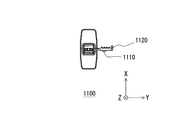
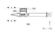
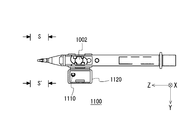
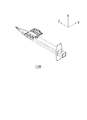
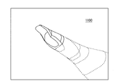
- a needle hole 1200 that is a hole for inserting a needle of a syringe filled with a viscoelastic substance into a stage lid portion 1120 and a tip of the needle of the syringe are needles.
- a guide wall portion 1110 for guiding to the hole 1200 is provided.
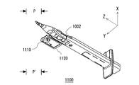
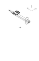
- a so-called three-piece intraocular lens 1002 is set in the nozzle body 1100 instead of the so-called one-piece intraocular lens 2 of the above embodiment.
- the tip portion of the nozzle body 1100 is configured in the same manner as in the above-described embodiment, so that an effect equivalent to that in the above-described embodiment can be expected using an insertion tool.
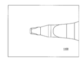
- FIG. 10A to 10C are perspective views of the nozzle body 1100 of the insertion device according to the modification.
- FIG. 10D is a diagram when the nozzle body 1100 is viewed from the Y-axis negative direction in the positive direction.
- FIG. 10E is a view of the nozzle body 1100 when viewed from the X axis positive direction to the negative direction.
- FIG. 10F is a view of the nozzle body 1100 when viewed from the Z-axis negative direction in the positive direction.
- FIG. 10G is a view of the nozzle body 1100 when viewed from the positive direction of the Z axis in the negative direction.
- FIG. 10H is a diagram when the nozzle body 1100 is viewed from the X axis positive direction to the negative direction.
- FIG. 10I is a diagram when the nozzle body 1100 is viewed from the X-axis negative direction to the positive direction.
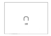
- FIG. 10J is a partially enlarged view of the nozzle body 1100 in the range indicated by “N” and “N ′” in FIG. 10A.
- FIG. 10K is a partially enlarged view of the nozzle body 1100 in the range indicated by “P” and “P ′” in FIG. 10B.
- FIG. 10L is a partially enlarged view of the nozzle body 1100 in the range indicated by “Q” and “Q ′” in FIG. 10D.
- FIG. 10M is a partially enlarged view of the nozzle body 1100 in the range indicated by “R” and “R ′” in FIG. 10H.
- FIG. 10N is a partially enlarged view of the nozzle body 1100 in the range indicated by “S” and “S ′” in FIG. 10I.
- FIG. 10P is a cross-sectional view of the nozzle body 1100 taken along line TT in FIG. 10L.
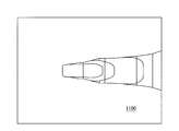
- FIG. 11A to 11C are perspective views of the nozzle body 1100 of the insertion device according to the modification.
- FIG. 11D is a diagram when the nozzle body 1100 is viewed in the positive direction from the Y-axis negative direction.
- FIG. 11E is a view of the nozzle body 1100 when viewed from the X axis positive direction to the negative direction.
- FIG. 11F is a view of the nozzle body 1100 when viewed from the negative Z-axis direction in the positive direction.
- FIG. 11G is a view of the nozzle body 1100 when viewed from the positive direction of the Z axis in the negative direction.
- FIG. 11H is a view of the nozzle body 1100 when viewed from the X axis positive direction to the negative direction.
- FIG. 11I is a diagram when the nozzle body 1100 is viewed from the X-axis negative direction to the positive direction.
- FIG. 11J is a partially enlarged view of the nozzle body 1100 in the range indicated by “U” and “U ′” in FIG. 11A.
- FIG. 11K is a partially enlarged view of the nozzle body 1100 in the range indicated by “V” and “V ′” in FIG. 11B.
- FIG. 11L is a partially enlarged view of the nozzle body 1100 in the range indicated by “W” and “W ′” in FIG. 11D.
- FIG. 11M is a partially enlarged view of the nozzle body 1100 in the range indicated by “X” and “X ′” in FIG. 11H.
- FIG. 11N is a partially enlarged view of the nozzle body 1100 in the range indicated by “Y” and “Y ′” in FIG. 11I.
- FIG. 11P is a cross-sectional view of the nozzle body 1100 taken along the line ZZ in FIG. 11L.
Landscapes
- Health & Medical Sciences (AREA)
- Ophthalmology & Optometry (AREA)
- Cardiology (AREA)
- Oral & Maxillofacial Surgery (AREA)
- Transplantation (AREA)
- Engineering & Computer Science (AREA)
- Biomedical Technology (AREA)
- Heart & Thoracic Surgery (AREA)
- Vascular Medicine (AREA)
- Life Sciences & Earth Sciences (AREA)
- Animal Behavior & Ethology (AREA)
- General Health & Medical Sciences (AREA)
- Public Health (AREA)
- Veterinary Medicine (AREA)
- Prostheses (AREA)
Abstract
Description
2、1002 眼内レンズ
100、1100 ノズル本体
100a ノズル本体の先端
100b ノズル本体の後端
100c 貫通孔
130 挿入筒部
130a 先端開口部
130b 先端領域
130c 突起部
130d 基端領域
130e 胴部
200 ステージ部
210 位置決め部材
220、1120 ステージ蓋部
300 プランジャ
1110 案内壁部
1200 ニードル孔
Claims (5)
- 眼内レンズを収容する略筒形状の本体部と、
前記本体部の先端に設けられた先端開口部と、
前記先端開口部の先端に設けられた略平板状の突起部と
を備え、
前記先端開口部の開口端面を前記本体部の中心軸に直交する面に対して傾斜した傾斜面とし、
前記先端開口部における先端側に、前記中心軸を挟んで互いに略平行な一対の側壁を有する先端領域が設けられている
ことを特徴とする眼内レンズの挿入器具。 - 前記先端開口部における後端側に、前記先端領域の後端と接続する基端領域が設けられており、
前記先端領域における傾斜面の前記中心軸に直交する面に対する傾斜角度が、前記基端領域における傾斜面の前記中心軸に直交する面に対する傾斜角度よりも小さい
ことを特徴とする請求項1に記載の眼内レンズの挿入器具。 - 前記先端開口部において、側方視で現れる輪郭線が、前記先端領域と前記基端領域との間に屈曲点を有することを特徴とする請求項2に記載の眼内レンズの挿入器具。
- 前記先端開口部の外周形状が、先端に向かって先細りになるテーパ形状であることを特徴とする請求項1から請求項3のいずれか1項に記載の眼内レンズの挿入器具。
- 前記本体部が前記眼内レンズの位置決め部材をさらに備え、
前記眼内レンズが前記位置決め部材によりあらかじめ位置決めされている
ことを特徴とする請求項1から請求項4のいずれか1項に記載の眼内レンズの挿入器具。
Priority Applications (3)
| Application Number | Priority Date | Filing Date | Title |
|---|---|---|---|
| EP14828661.0A EP3025677A4 (en) | 2013-07-24 | 2014-07-24 | Intraocular-lens-inserting instrument |
| JP2015528334A JP6524588B2 (ja) | 2013-07-24 | 2014-07-24 | 眼内レンズの挿入器具 |
| US14/907,184 US10213295B2 (en) | 2013-07-24 | 2014-07-24 | Intraocular lens insertion apparatus |
Applications Claiming Priority (2)
| Application Number | Priority Date | Filing Date | Title |
|---|---|---|---|
| JP2013153752 | 2013-07-24 | ||
| JP2013-153752 | 2013-07-24 |
Publications (1)
| Publication Number | Publication Date |
|---|---|
| WO2015012355A1 true WO2015012355A1 (ja) | 2015-01-29 |
Family
ID=52393388
Family Applications (1)
| Application Number | Title | Priority Date | Filing Date |
|---|---|---|---|
| PCT/JP2014/069573 WO2015012355A1 (ja) | 2013-07-24 | 2014-07-24 | 眼内レンズの挿入器具 |
Country Status (4)
| Country | Link |
|---|---|
| US (1) | US10213295B2 (ja) |
| EP (1) | EP3025677A4 (ja) |
| JP (1) | JP6524588B2 (ja) |
| WO (1) | WO2015012355A1 (ja) |
Families Citing this family (2)
| Publication number | Priority date | Publication date | Assignee | Title |
|---|---|---|---|---|
| JP6511065B2 (ja) * | 2013-11-15 | 2019-05-15 | メディセル・アーゲー | 眼内レンズを受承するデバイス及び眼内レンズを折り畳む方法 |
| BE1024131B1 (fr) * | 2016-04-21 | 2017-11-20 | Physiol S.A. | Dispositif d'injection de lentille intraoculaire souple et navette de stockage pour sa mise en œuvre |
Citations (3)
| Publication number | Priority date | Publication date | Assignee | Title |
|---|---|---|---|---|
| JP2008307376A (ja) | 2007-06-12 | 2008-12-25 | Alcon Inc | ウーン・アシステッド送達用のレンズ注入器用管腔チップ |
| JP2009160153A (ja) | 2007-12-28 | 2009-07-23 | Menicon Co Ltd | 眼内レンズの挿入器具 |
| JP2012125361A (ja) * | 2010-12-14 | 2012-07-05 | Kowa Co | 眼内レンズの挿入器具 |
Family Cites Families (2)
| Publication number | Priority date | Publication date | Assignee | Title |
|---|---|---|---|---|
| GB0010871D0 (en) * | 2000-05-06 | 2000-06-28 | Duckworth & Kent Ltd | Opthalmic injector |
| JP4927473B2 (ja) * | 2006-08-11 | 2012-05-09 | 興和株式会社 | 眼内レンズの挿入器具 |
-
2014
- 2014-07-24 JP JP2015528334A patent/JP6524588B2/ja active Active
- 2014-07-24 EP EP14828661.0A patent/EP3025677A4/en not_active Withdrawn
- 2014-07-24 WO PCT/JP2014/069573 patent/WO2015012355A1/ja active Application Filing
- 2014-07-24 US US14/907,184 patent/US10213295B2/en active Active
Patent Citations (3)
| Publication number | Priority date | Publication date | Assignee | Title |
|---|---|---|---|---|
| JP2008307376A (ja) | 2007-06-12 | 2008-12-25 | Alcon Inc | ウーン・アシステッド送達用のレンズ注入器用管腔チップ |
| JP2009160153A (ja) | 2007-12-28 | 2009-07-23 | Menicon Co Ltd | 眼内レンズの挿入器具 |
| JP2012125361A (ja) * | 2010-12-14 | 2012-07-05 | Kowa Co | 眼内レンズの挿入器具 |
Non-Patent Citations (1)
| Title |
|---|
| See also references of EP3025677A4 * |
Also Published As
| Publication number | Publication date |
|---|---|
| EP3025677A1 (en) | 2016-06-01 |
| JP6524588B2 (ja) | 2019-06-05 |
| US20160175090A1 (en) | 2016-06-23 |
| US10213295B2 (en) | 2019-02-26 |
| EP3025677A4 (en) | 2017-03-15 |
| JPWO2015012355A1 (ja) | 2017-03-02 |
Similar Documents
| Publication | Publication Date | Title |
|---|---|---|
| JP6753966B2 (ja) | 眼内レンズの挿入器具 | |
| WO2015012312A1 (ja) | 眼内レンズの挿入器具 | |
| JP6258865B2 (ja) | 眼内レンズの挿入器具 | |
| WO2016195095A1 (ja) | 眼内レンズ挿入器具 | |
| WO2015012355A1 (ja) | 眼内レンズの挿入器具 | |
| JP6027536B2 (ja) | 眼内レンズの挿入器具 | |
| JP6614615B2 (ja) | 眼内レンズの挿入器具 | |
| JP6669346B2 (ja) | 眼内レンズ挿入器具 | |
| JP6627267B2 (ja) | 眼内レンズ挿入器具 | |
| TW201919551A (zh) | 人工水晶體植入器具 | |
| JP6575761B2 (ja) | 眼内レンズの挿入器具 | |
| WO2017030139A1 (ja) | 眼内レンズ挿入器具 | |
| JP6601945B2 (ja) | 眼内レンズ挿入器具 | |
| JP2018198747A (ja) | 眼内レンズおよび眼内レンズ挿入器具 | |
| JP2017080329A (ja) | 眼内レンズ挿入器具 | |
| WO2020054641A1 (ja) | 眼内レンズ挿入器具 | |
| JP2016077605A (ja) | 眼内レンズの挿入器具 | |
| WO2016017772A1 (ja) | 眼内レンズの挿入器具 |
Legal Events
| Date | Code | Title | Description |
|---|---|---|---|
| 121 | Ep: the epo has been informed by wipo that ep was designated in this application |
Ref document number: 14828661 Country of ref document: EP Kind code of ref document: A1 |
|
| ENP | Entry into the national phase |
Ref document number: 2015528334 Country of ref document: JP Kind code of ref document: A |
|
| WWE | Wipo information: entry into national phase |
Ref document number: 14907184 Country of ref document: US |
|
| NENP | Non-entry into the national phase |
Ref country code: DE |
|
| WWE | Wipo information: entry into national phase |
Ref document number: 2014828661 Country of ref document: EP |