WO2015008437A1 - ズームレンズ、光学機器及びズームレンズの製造方法 - Google Patents
ズームレンズ、光学機器及びズームレンズの製造方法 Download PDFInfo
- Publication number
- WO2015008437A1 WO2015008437A1 PCT/JP2014/003413 JP2014003413W WO2015008437A1 WO 2015008437 A1 WO2015008437 A1 WO 2015008437A1 JP 2014003413 W JP2014003413 W JP 2014003413W WO 2015008437 A1 WO2015008437 A1 WO 2015008437A1
- Authority
- WO
- WIPO (PCT)
- Prior art keywords
- lens
- lens group
- zoom lens
- group
- conditional expression
- Prior art date
- Legal status (The legal status is an assumption and is not a legal conclusion. Google has not performed a legal analysis and makes no representation as to the accuracy of the status listed.)
- Ceased
Links
Images

Classifications
-
- G—PHYSICS
- G02—OPTICS
- G02B—OPTICAL ELEMENTS, SYSTEMS OR APPARATUS
- G02B15/00—Optical objectives with means for varying the magnification
- G02B15/14—Optical objectives with means for varying the magnification by axial movement of one or more lenses or groups of lenses relative to the image plane for continuously varying the equivalent focal length of the objective
- G02B15/16—Optical objectives with means for varying the magnification by axial movement of one or more lenses or groups of lenses relative to the image plane for continuously varying the equivalent focal length of the objective with interdependent non-linearly related movements between one lens or lens group, and another lens or lens group
-
- G—PHYSICS
- G02—OPTICS
- G02B—OPTICAL ELEMENTS, SYSTEMS OR APPARATUS
- G02B13/00—Optical objectives specially designed for the purposes specified below
- G02B13/001—Miniaturised objectives for electronic devices, e.g. portable telephones, webcams, PDAs, small digital cameras
- G02B13/009—Miniaturised objectives for electronic devices, e.g. portable telephones, webcams, PDAs, small digital cameras having zoom function
-
- G—PHYSICS
- G02—OPTICS
- G02B—OPTICAL ELEMENTS, SYSTEMS OR APPARATUS
- G02B15/00—Optical objectives with means for varying the magnification
- G02B15/14—Optical objectives with means for varying the magnification by axial movement of one or more lenses or groups of lenses relative to the image plane for continuously varying the equivalent focal length of the objective
- G02B15/144—Optical objectives with means for varying the magnification by axial movement of one or more lenses or groups of lenses relative to the image plane for continuously varying the equivalent focal length of the objective having four groups only
- G02B15/1441—Optical objectives with means for varying the magnification by axial movement of one or more lenses or groups of lenses relative to the image plane for continuously varying the equivalent focal length of the objective having four groups only the first group being positive
- G02B15/144113—Optical objectives with means for varying the magnification by axial movement of one or more lenses or groups of lenses relative to the image plane for continuously varying the equivalent focal length of the objective having four groups only the first group being positive arranged +-++
-
- G—PHYSICS
- G02—OPTICS
- G02B—OPTICAL ELEMENTS, SYSTEMS OR APPARATUS
- G02B27/00—Optical systems or apparatus not provided for by any of the groups G02B1/00 - G02B26/00, G02B30/00
- G02B27/0025—Optical systems or apparatus not provided for by any of the groups G02B1/00 - G02B26/00, G02B30/00 for optical correction, e.g. distorsion, aberration
-
- G—PHYSICS
- G02—OPTICS
- G02B—OPTICAL ELEMENTS, SYSTEMS OR APPARATUS
- G02B27/00—Optical systems or apparatus not provided for by any of the groups G02B1/00 - G02B26/00, G02B30/00
- G02B27/64—Imaging systems using optical elements for stabilisation of the lateral and angular position of the image
- G02B27/646—Imaging systems using optical elements for stabilisation of the lateral and angular position of the image compensating for small deviations, e.g. due to vibration or shake
Definitions
- the present invention relates to a zoom lens, an optical device, and a method for manufacturing a zoom lens.
- the present invention has been made in view of such problems, and an object of the present invention is to provide a zoom lens, an optical apparatus, and a zoom lens manufacturing method that are small and have excellent optical performance.
- a zoom lens according to the present invention includes a first lens group having a positive refractive power and a second lens having a negative refractive power, which are arranged in order from the object side along the optical axis.
- the fourth lens group once moves to the object side and then moves to the image side, and the third lens group is arranged in order from the object side along the optical axis.
- the positive lens, the positive lens, and the negative lens And the following conditional expression is satisfied.
- TLt total length of the zoom lens in the telephoto end state
- fw focal length of the entire zoom lens system in the wide-angle end state
- ft focal length of the entire zoom lens system in the telephoto end state.
- the second lens group includes a first negative lens, a second negative lens, and a positive lens arranged in order from the object side along the optical axis. It is preferable to satisfy the conditional expression.
- f2b focal length of the second negative lens of the second lens group.
- the zoom lens according to the present invention preferably satisfies the following conditional expression.
- f1 Focal length of the first lens group.
- the zoom lens according to the present invention preferably satisfies the following conditional expression.
- f1 the focal length of the first lens group
- f2 focal length of the second lens group
- the zoom lens according to the present invention preferably satisfies the following conditional expression.
- Nd Refractive index with respect to d-line of the negative lens of the third lens group
- the second lens group includes a negative lens having at least one aspheric surface.
- the fourth lens group includes a positive lens and satisfies the following conditional expression.
- R41 Paraxial radius of curvature of the object side lens surface of the positive lens of the fourth lens group
- R42 Paraxial radius of curvature of the image side lens surface of the positive lens of the fourth lens group.
- the zoom lens according to the present invention preferably satisfies the following conditional expression.
- f3 focal length of the third lens group
- f4 focal length of the fourth lens group
- the optical apparatus according to the present invention includes any one of the above zoom lenses.
- the zoom lens manufacturing method includes a first lens group having a positive refractive power, a second lens group having a negative refractive power, and a positive refraction arranged in order from the object side along the optical axis.
- a zoom lens manufacturing method having a third lens group having power and a fourth lens group having positive refractive power, wherein the distance between the lens groups is changed upon zooming from the wide-angle end state to the telephoto end state. And the fourth lens group once moves to the image side after moving to the object side, and the third lens group is arranged in order from the object side along the optical axis, the positive lens, the positive lens, and the negative lens.
- Each lens is arranged in a lens barrel so that the following conditional expression is satisfied.
- TLt total length of the zoom lens in the telephoto end state
- fw focal length of the entire zoom lens system in the wide-angle end state
- ft focal length of the entire zoom lens system in the telephoto end state.
- the present invention it is possible to provide a zoom lens, an optical apparatus, and a zoom lens manufacturing method that are small and have excellent optical performance.
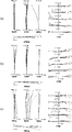
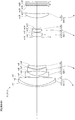
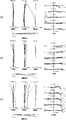
- FIG. 6 is a diagram illustrating various aberrations of the zoom lens according to Example 1, where (a) illustrates a wide angle end state, (b) illustrates an intermediate focal length state, and (c) illustrates various aberrations when focusing on an object at infinity in a telephoto end state. It is. It is a figure which shows the structure of the zoom lens which concerns on 2nd Example, and the movement locus
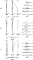
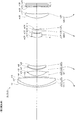
- FIG. 6 is a diagram illustrating various aberrations of the zoom lens according to Example 2, wherein (a) is a wide-angle end state, (b) is an intermediate focal length state, and (c) is an aberration diagram when focusing on an object at infinity in a telephoto end state. It is. It is a figure which shows the structure of the zoom lens concerning 3rd Example, and the movement locus
- FIG. 7A is a diagram illustrating various aberrations of the zoom lens according to Example 3, where FIG. 9A is a diagram illustrating various aberrations when focusing on an object at infinity in the wide-angle end state, FIG. It is.
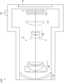
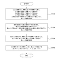
- FIG. 8 is a cross-sectional view taken along arrow AA ′ in FIG. It is a flowchart which shows the manufacturing method of a zoom lens.
- the zoom lens ZL includes a first lens group G1 having a positive refractive power, a second lens group G2 having a negative refractive power, and a first lens group having a positive refractive power.
- a third lens group G3 and a fourth lens group G4 having a positive refractive power, and the third lens group G3 is arranged in order from the object side along the optical axis, a positive lens, a positive lens, and a negative lens And a lens.
- the third lens group G3 is more preferably composed of only two positive lenses and one negative lens arranged in order from the object side along the optical axis.
- the first lens group G1 to the fourth lens group G4 move so that the distance between the lens groups changes during zooming from the wide-angle end state to the telephoto end state. Further, in this embodiment, upon zooming, the distance between the first lens group G1 and the second lens group G2 increases, the distance between the second lens group G2 and the third lens group G3 decreases, and the third lens. The distance between the group G3 and the fourth lens group G4 increases. Further, in the present embodiment, at the time of zooming, the fourth lens group G4 once moves to the object side and then moves to the image side. By moving the fourth lens group G4 in this way, it is possible to contribute to downsizing of the zoom lens ZL.
- the zoom lens ZL according to the present embodiment satisfies the following conditional expression (1).
- TLt total length of the zoom lens ZL in the telephoto end state
- fw focal length of zoom lens ZL in the wide-angle end state
- ft focal length of the zoom lens ZL in the telephoto end state.
- Conditional expression (1) defines the total length of the zoom lens ZL in the telephoto end state (distance on the optical axis from the foremost lens surface to the image plane). If the upper limit value of conditional expression (1) is exceeded, the total length of the zoom lens ZL becomes large with respect to the focal length, and miniaturization cannot be achieved. In order to alleviate this, for example, when the power of the third lens group G3 is increased to reduce the size, spherical aberration and chromatic aberration are deteriorated. If the lower limit value of conditional expression (1) is not reached, the power of the first lens group G1 is increased to increase the focal length with respect to the entire length of the zoom lens ZL, and the spherical aberration and the longitudinal chromatic aberration are deteriorated.
- the second lens group G2 includes a first negative lens, a second negative lens, and a positive lens arranged in order from the object side along the optical axis. It is preferable that the following conditional expression (2) is satisfied.
- the second lens group G2 is more preferably composed of only two negative lenses and one positive lens arranged in order from the object side.
- f2b focal length of the second negative lens of the second lens group G2.
- Conditional expression (2) defines the focal length of the second negative lens of the second lens group G2. If the upper limit value of conditional expression (2) is exceeded, the power of the second negative lens in the second lens group G2 becomes weak, so that the distortion in the wide-angle end state deteriorates. When the lower limit value of conditional expression (2) is not reached, astigmatism in the wide-angle end state deteriorates. In addition, since the radius of curvature becomes small, it is necessary to ensure a space between adjacent lenses, and the zoom lens ZL becomes large.
- conditional expression (2) In order to ensure the effect of the present embodiment, it is preferable to set the lower limit value of conditional expression (2) to 0.60. In order to secure the effect of the present embodiment, it is preferable to set the lower limit of conditional expression (2) to 0.65.
- the zoom lens ZL according to the present embodiment satisfies the following conditional expression (3).
- f1 Focal length of the first lens group G1.
- Conditional expression (3) defines the relationship between the focal length of the first lens group G1 and the focal length of the zoom lens ZL in the telephoto end state. If the upper limit value of conditional expression (3) is exceeded, the power of the first lens group G1 becomes weak, and the distortion aberration in the wide-angle end state deteriorates. If the lower limit value of conditional expression (3) is not reached, the power of the first lens group G1 becomes strong, and spherical aberration and lateral chromatic aberration in the telephoto end state deteriorate.
- the zoom lens ZL according to the present embodiment satisfies the following conditional expression (4).
- f1 Focal length of the first lens group G1
- f2 focal length of the second lens group G2.
- Conditional expression (4) defines the relationship between the focal length of the first lens group G1 and the focal length of the second lens group G2.
- the upper limit value of conditional expression (4) is exceeded, the power of the first lens group G1 becomes weak, and the distortion in the wide-angle end state becomes worse. Further, as the power of the second lens group G2 increases and the zoom ratio increases, the overall length of the zoom lens ZL increases. If the lower limit of conditional expression (4) is not reached, the power of the second lens group G2 will become strong, and astigmatism and field curvature will deteriorate.
- conditional expression (4) it is preferable to set the lower limit of conditional expression (4) to 5.0.
- the zoom lens ZL according to the present embodiment satisfies the following conditional expression (5).
- Nd Refractive index with respect to d-line of the negative lens of the third lens group G3.
- Conditional expression (5) defines an appropriate refractive index of the negative lens of the third lens group G3. If the upper limit value of conditional expression (5) is exceeded, axial chromatic aberration in the telephoto end state deteriorates. If the lower limit of conditional expression (5) is not reached, the Petzval sum increases, so that the field curvature in the intermediate focal length state deteriorates.
- conditional expression (5) it is preferable to set the upper limit of conditional expression (5) to 2.20.
- conditional expression (5) it is preferable to set the lower limit of conditional expression (5) to 2.00.
- the second lens group G preferably includes a negative lens having at least one aspheric surface.
- the fourth lens group G4 has a positive lens and satisfies the following conditional expression (6). If the fourth lens group G4 is composed of one lens that satisfies the conditional expression (6), the configuration can be simplified, and the fourth lens group G4 that moves to the image side after moving once to the object side at the time of zooming. The weight of can be reduced, and it is more preferable.
- R41 Paraxial radius of curvature of the object side lens surface of the positive lens in the fourth lens group G4
- R42 Paraxial radius of curvature of the image side lens surface of the positive lens in the fourth lens group G4.
- Conditional expression (6) defines the shape factor of the positive lens in the fourth lens group G4. If the upper limit value of conditional expression (6) is exceeded, coma aberration will deteriorate from the intermediate focal length state to the telephoto end state. If the lower limit value of conditional expression (6) is not reached, the fluctuation of the image plane increases from the intermediate focal length state to the telephoto end state.
- the zoom lens ZL according to the present embodiment satisfies the following conditional expression (7).
- f3 focal length of the third lens group G3
- f4 focal length of the fourth lens group G4.
- Conditional expression (7) defines the relationship between the focal length of the third lens group G3 and the focal length of the fourth lens group G4. If the upper limit value of conditional expression (7) is exceeded, the power of the fourth lens group G4 becomes stronger, the spherical aberration and axial chromatic aberration in the telephoto end state worsen, and the amount of movement of the third lens group G3 increases. The overall length of the zoom lens ZL becomes large, and miniaturization cannot be achieved. If the lower limit of conditional expression (7) is not reached, the power of the fourth lens group G4 becomes weak, and the field curvature in the wide-angle end state, coma aberration, and coma aberration in the telephoto end state deteriorate.
- conditional expression (7) it is preferable to set the upper limit of conditional expression (7) to 0.50.
- conditional expression (7) it is preferable to set the lower limit of conditional expression (7) to 0.30.
- zoom lens ZL According to the zoom lens ZL according to the present embodiment having the above-described configuration, a zoom lens having a small size and excellent optical performance can be realized.
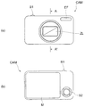
- FIG. 7 and 8 show a configuration of a digital still camera CAM (optical device) as an optical device including the zoom lens ZL described above.
- a digital still camera CAM optical device
- a power button not shown
- a shutter not shown
- light from the subject (object) is condensed by the zoom lens ZL, and an image is displayed.
- An image is formed on an image sensor C (for example, a CCD or a CMOS) disposed on the surface I (see FIG. 1).
- the subject image formed on the image sensor C is displayed on the liquid crystal monitor M disposed behind the digital still camera CAM.
- the photographer determines the composition of the subject image while looking at the liquid crystal monitor M, and then depresses the release button B1 to photograph the subject image with the image sensor C, and records and saves it in a memory (not shown).
- the camera CAM is provided with an auxiliary light emitting unit EF for emitting auxiliary light when the subject is dark, a function button B2 used for setting various conditions of the digital still camera CAM, and the like.
- auxiliary light emitting unit EF for emitting auxiliary light when the subject is dark
- function button B2 used for setting various conditions of the digital still camera CAM
- a compact type camera in which the camera CAM and the zoom lens ZL are integrally formed is illustrated.
- a single lens reflex camera in which a lens barrel having the zoom lens ZL and a camera body main body can be attached and detached is used. good.
- the above zoom lens ZL is mounted as a photographing lens, so that the camera has a small zoom ratio and excellent optical performance while having a high zoom ratio. Can be realized.
- a manufacturing method of the above-described zoom lens ZL will be described with reference to FIG. First, a first lens group G1 having a positive refractive power and a second lens having a negative refractive power arranged in order from the object side along the optical axis and from the object side along the optical axis.
- the lenses are arranged so that the lens group G2, the third lens group G3 having a positive refractive power, and the fourth lens group G4 having a positive refractive power are arranged (step ST10).
- the distance between the lens groups changes, and each lens is moved so that the fourth lens group G4 once moves to the object side and then moves to the image side.
- step ST20 Arrange (step ST20).
- the lenses are arranged so as to have a positive lens, a positive lens, and a negative lens arranged in order from the object side along the optical axis (step ST30). Then, each lens is arranged so as to satisfy the following conditional expression (1) (step ST40).
- TLt total length of the zoom lens ZL in the telephoto end state
- fw focal length of the entire zoom lens ZL system in the wide-angle end state
- ft focal length of the entire zoom lens ZL system in the telephoto end state.
- the first lens group G1 having positive refractive power is convex from the object side to the object side along the optical axis.
- Each lens is incorporated in the lens barrel so that the negative meniscus lens L11 facing the lens and the positive biconvex lens L12 are arranged in this order.
- the negative meniscus lens L11 and the positive lens L12 are bonded to form a cemented lens.
- a biconcave negative lens L21, a biconcave negative lens L22, and a positive meniscus lens having a convex surface facing the object side Each lens is incorporated in the lens barrel so as to be arranged in the order of L23.
- a biconvex positive lens L31, a positive meniscus lens L32 having a convex surface facing the object side, and a convex surface facing the object side The lenses are incorporated in the lens barrel so that the negative meniscus lenses L33 are arranged in this order.
- the positive lens L32 and the negative lens L33 are bonded together to form a cemented lens.
- a positive meniscus lens L41 having a convex surface directed toward the object side is incorporated in the lens barrel.
- Each lens is incorporated in the lens barrel so as to satisfy the conditional expression (1) (the corresponding value of the conditional expression (1) is 3.1857).
- the manufacturing method of the zoom lens ZL described above it is possible to manufacture a zoom lens that is small and has excellent optical performance while having a high zoom ratio.
- Tables 1 to 3 are shown below. These are tables of specifications in the first to third examples.
- each reference symbol for FIG. 1 according to the first embodiment is used independently for each embodiment in order to avoid complication of explanation due to an increase in the number of digits of the reference symbol. Therefore, even if the same reference numerals as those in the drawings according to the other embodiments are given, they are not necessarily in the same configuration as the other embodiments.
- C-line (wavelength 656.2730 nm), d-line (wavelength 587.5620 nm), F-line (wavelength 486.1330 nm), and g-line (wavelength 435.8350 nm) are selected as the aberration characteristic calculation targets.
- the surface number is the order of the optical surfaces from the object side along the light traveling direction
- R is the radius of curvature of each optical surface
- D is the next optical surface from each optical surface
- Or nd is the refractive index of the material of the optical member with respect to the d-line
- ⁇ d is the Abbe number based on the d-line of the material of the optical member.
- the object plane is the object plane
- (variable) is the variable plane spacing
- the curvature radius “ ⁇ ” is the plane or aperture
- (aperture S) is the aperture stop S
- the image plane is the image plane I.
- the refractive index of air “1.000000” is omitted.
- f is the focal length of the entire lens system
- FNo is the F number
- ⁇ is the half field angle (maximum incident angle, unit: °)
- Y is the image height
- Bf is on the optical axis.
- the distance from the final lens surface of the fourth lens group G4 to the paraxial image plane, and Bf (air equivalent) is paraxial from the final lens surface on the optical axis (that is, the fourth lens group G4).
- the distance to the image plane in terms of air, TL indicates the total lens length (the distance from the lens frontmost surface to the lens final surface on the optical axis plus Bf).
- Di represents a variable interval between the i-th surface and the (i + 1) -th surface.
- G is the group number
- the first group surface is the surface number of the most object side of each group
- the group focal length is the focal length of each group
- the lens configuration length is the most object side of each group The distance on the optical axis from the lens surface to the lens surface closest to the image plane is shown.
- mm is generally used as the focal length f, the radius of curvature R, the surface interval D, and other lengths, etc. unless otherwise specified, but the zoom lens is proportionally enlarged. Alternatively, the same optical performance can be obtained even by proportional reduction, and the present invention is not limited to this. Further, the unit is not limited to “mm”, and other appropriate units can be used.
- the zoom lens ZL (ZL1) includes a first lens group G1 having a positive refractive power arranged in order from the object side along the optical axis, and a negative refractive power.
- the first lens group G1 is composed of a cemented lens of a negative meniscus lens L11 having a convex surface facing the object side and a biconvex positive lens L12 arranged in order from the object side along the optical axis.
- the image side lens surface of the positive lens L12 is aspheric.
- the second lens group G2 includes a biconcave negative lens L21, a biconcave negative lens L22, and a positive meniscus lens L23 having a convex surface facing the object, which are arranged in order from the object side along the optical axis. Composed.
- the image side lens surface of the negative lens L21 is an aspherical surface.
- the third lens group G3 includes a biconvex positive lens L31 arranged in order from the object side along the optical axis, a positive meniscus lens L32 having a convex surface on the object side, and a negative meniscus lens having a convex surface on the object side. And a cemented lens with L33. Both surfaces of the positive lens L31 are aspheric.
- the fourth lens group G4 includes a positive meniscus lens L41 having a convex surface directed toward the object side.
- the image side lens surface of the positive meniscus lens L41 is an aspherical surface.
- the aperture stop S for adjusting the light amount is disposed closer to the object side than the positive lens L31 located closest to the object side of the third lens group G3.
- the filter group FL is disposed between the fourth lens group G4 and the image plane I.
- the filter group FL is composed of a low-pass filter, an infrared cut filter, or the like for cutting a spatial frequency equal to or higher than the limit resolution of the solid-state imaging device, such as a CCD disposed on the image plane I.
- the distance between the first lens group G1 and the second lens group G2 increases during zooming from the wide-angle end state to the telephoto end state, and the second lens group G2 and the third lens are increased.
- Each lens group moves so that the distance between the group G3 decreases and the distance between the third lens group G3 and the fourth lens group G4 increases. Further, at the time of zooming, the aperture stop S moves together with the third lens group G3.
- the zoom lens ZL1 performs focusing from an object at infinity to an object at a finite distance by moving the fourth lens group G4 along the optical axis.
- Table 1 below shows the values of each item in the first example.
- Surface numbers 1 to 21 in Table 1 correspond to the optical surfaces m1 to m21 shown in FIG.
- FIG. 2 is a diagram showing various aberrations (spherical aberration diagram, astigmatism diagram, distortion aberration diagram, coma aberration diagram and magnification chromatic aberration diagram) of the zoom lens ZL1 according to the first example, and (a) is a wide-angle end state, (B) is an intermediate focal length state, (c) is a diagram of various aberrations during focusing on an object at infinity in the telephoto end state.
- FNO represents an F number
- A represents a half angle of view (unit: °) with respect to each image height.
- d is the d-line
- g is the g-line
- C is the C-line
- F is the F-line aberration.
- the solid line indicates the sagittal image plane
- the broken line indicates the meridional image plane. Note that the same reference numerals as in this embodiment are used in the aberration diagrams of each embodiment described later.
- the zoom lens ZL1 according to the first example has various aberrations well corrected in each focal length state from the wide-angle end state to the telephoto end state, and has excellent optical performance. It can be seen that
- the zoom lens ZL (ZL2) according to the second example includes a first lens group G1 having a positive refractive power arranged in order from the object side along the optical axis, and a negative refractive power.
- the first lens group G1 is composed of a cemented lens of a negative meniscus lens L11 having a convex surface facing the object side and a biconvex positive lens L12 arranged in order from the object side along the optical axis.
- the image side lens surface of the positive lens L12 is aspheric.
- the second lens group G2 includes a biconcave negative lens L21, a biconcave negative lens L22, and a positive meniscus lens L23 having a convex surface facing the object, which are arranged in order from the object side along the optical axis. Composed. Both surfaces of the negative lens L22 are aspheric.
- the third lens group G3 includes a biconvex positive lens L31 arranged in order from the object side along the optical axis, a positive meniscus lens L32 having a convex surface on the object side, and a negative meniscus lens having a convex surface on the object side. And a cemented lens with L33. Both surfaces of the positive lens L31 are aspheric.
- the fourth lens group G4 includes a positive meniscus lens L41 having a convex surface directed toward the object side.
- the object side lens surface of the positive meniscus lens L41 is aspheric.
- the aperture stop S for adjusting the light amount is disposed closer to the object side than the positive lens L31 located closest to the object side of the third lens group G3.
- the filter group FL is disposed between the fourth lens group G4 and the image plane I.
- the filter group FL is composed of a low-pass filter, an infrared cut filter, or the like for cutting a spatial frequency equal to or higher than the limit resolution of the solid-state imaging device, such as a CCD disposed on the image plane I.
- the distance between the first lens group G1 and the second lens group G2 increases during zooming from the wide-angle end state to the telephoto end state, and the second lens group G2 and the third lens are increased.
- Each lens group moves so that the distance between the group G3 decreases and the distance between the third lens group G3 and the fourth lens group G4 increases.
- the aperture stop S moves together with the third lens group G3.
- the zoom lens ZL2 performs focusing from an object at infinity to an object at a finite distance by moving the fourth lens group G4 along the optical axis.
- Table 2 shows the values of each item in the second example.
- Surface numbers 1 to 21 in Table 2 correspond to the optical surfaces m1 to m21 shown in FIG.
- FIG. 4 is a diagram showing various aberrations (spherical aberration diagram, astigmatism diagram, distortion diagram, coma aberration diagram, and chromatic aberration diagram of magnification) of the zoom lens ZL2 according to Example 2, wherein (a) is a wide-angle end state, (B) is an intermediate focal length state, (c) is a diagram of various aberrations during focusing on an object at infinity in the telephoto end state.
- the zoom lens ZL2 according to the second example has various aberrations well corrected in each focal length state from the wide-angle end state to the telephoto end state, and excellent optical performance. It can be seen that
- the zoom lens ZL (ZL3) according to the third example includes a first lens group G1 having a positive refractive power arranged in order from the object side along the optical axis, and a negative refractive power.
- the first lens group G1 is composed of a cemented lens of a negative meniscus lens L11 having a convex surface facing the object side and a biconvex positive lens L12 arranged in order from the object side along the optical axis.
- the image side lens surface of the positive lens L12 is aspheric.
- the second lens group G2 includes a biconcave negative lens L21, a biconcave negative lens L22, and a positive meniscus lens L23 having a convex surface facing the object, which are arranged in order from the object side along the optical axis. Composed. Both surfaces of the negative lens L22 are aspheric.
- the third lens group G3 includes a biconvex positive lens L31 arranged in order from the object side along the optical axis, a positive meniscus lens L32 having a convex surface on the object side, and a negative meniscus lens having a convex surface on the object side. And a cemented lens with L33. Both surfaces of the positive lens L31 are aspheric.
- the fourth lens group G4 includes a positive meniscus lens L41 having a convex surface directed toward the object side.
- the object side lens surface of the positive meniscus lens L41 is aspheric.
- the aperture stop S for adjusting the light amount is disposed closer to the object side than the positive lens L31 located closest to the object side of the third lens group G3.
- the filter group FL is disposed between the fourth lens group G4 and the image plane I.
- the filter group FL is composed of a low-pass filter, an infrared cut filter, or the like for cutting a spatial frequency equal to or higher than the limit resolution of the solid-state imaging device, such as a CCD disposed on the image plane I.
- the distance between the first lens group G1 and the second lens group G2 increases during zooming from the wide-angle end state to the telephoto end state, and the second lens group G2 and the third lens are increased.
- Each lens group moves so that the distance between the group G3 decreases and the distance between the third lens group G3 and the fourth lens group G4 increases.
- the aperture stop S moves together with the third lens group G3.
- the zoom lens ZL3 performs focusing from an object at infinity to an object at a finite distance by moving the fourth lens group G4 along the optical axis.
- Table 3 shows the values of each item in the third example.
- Surface numbers 1 to 21 in Table 3 correspond to the optical surfaces m1 to m21 shown in FIG.
- FIG. 6 is a diagram showing various aberrations (spherical aberration diagram, astigmatism diagram, distortion diagram, coma aberration diagram and chromatic aberration diagram of magnification) of the zoom lens ZL3 according to Example 3, wherein (a) is a wide-angle end state, (B) is an intermediate focal length state, (c) is a diagram of various aberrations during focusing on an object at infinity in the telephoto end state.
- the zoom lens ZL3 according to the third example has various aberrations corrected well in each focal length state from the wide-angle end state to the telephoto end state, and excellent optical performance. It can be seen that
- a four-group configuration is shown, but the present invention can also be applied to other group configurations such as a 5-group and a 6-group. Further, a configuration in which a lens or a lens group is added to the most object side, or a configuration in which a lens or a lens group is added to the most image side may be used.
- the lens group refers to a portion having at least one lens separated by an air interval that changes during zooming.
- a single lens group or a plurality of lens groups, or a partial lens group may be moved in the optical axis direction to be a focusing lens group that performs focusing from an object at infinity to a near object.
- This focusing lens group can be applied to autofocus, and is also suitable for driving a motor for autofocus (using an ultrasonic motor or the like).
- the entire fourth lens group G4 is the focusing lens group, but a partial group of the fourth lens group G4 may be the focusing lens group.
- the lens group or the partial lens group is moved so as to have a component in a direction perpendicular to the optical axis, or is rotated (swayed) in the in-plane direction including the optical axis to reduce image blur caused by camera shake.
- An image stabilizing lens group to be corrected may be used.
- the entire third lens group G3 is the anti-vibration lens group, but a partial group of the third lens group G3 may be the anti-vibration lens group.
- the lens surface may be formed as a spherical or flat surface or an aspherical surface.
- the lens surface is a spherical surface or a flat surface, lens processing and assembly adjustment are facilitated, and optical performance deterioration due to processing and assembly adjustment errors can be prevented. Further, even when the image plane is deviated, it is preferable because there is little deterioration in drawing performance.
- the lens surface is an aspheric surface, the aspheric surface is an aspheric surface by grinding, a glass mold aspheric surface made of glass with an aspheric shape, or a composite aspheric surface made of resin with an aspheric shape on the glass surface. Any aspherical surface may be used.
- the lens surface may be a diffractive surface, and the lens may be a gradient index lens (GRIN lens) or a plastic lens.
- GRIN lens gradient index lens
- the aperture stop is preferably arranged in the vicinity of the third lens group, but the role of the aperture stop may be substituted by a lens frame without providing a member as an aperture stop.
- Each lens surface may be provided with an antireflection film having high transmittance in a wide wavelength range in order to reduce flare and ghost and achieve high optical performance with high contrast.
Landscapes
- Physics & Mathematics (AREA)
- General Physics & Mathematics (AREA)
- Optics & Photonics (AREA)
- Nonlinear Science (AREA)
- Lenses (AREA)
- Adjustment Of Camera Lenses (AREA)
Abstract
Description
但し、
TLt:望遠端状態における前記ズームレンズの全長、
fw:広角端状態における前記ズームレンズ全系の焦点距離、
ft:望遠端状態における前記ズームレンズ全系の焦点距離。
但し、
f2b:前記第2レンズ群の前記第2の負レンズの焦点距離。
但し、
f1:前記第1レンズ群の焦点距離。
但し、
f1:前記第1レンズ群の焦点距離、
f2:前記第2レンズ群の焦点距離。
但し、
Nd:前記第3レンズ群の前記負レンズのd線に対する屈折率。
但し、
R41:前記第4レンズ群の前記正レンズの物体側レンズ面の近軸曲率半径、
R42:前記第4レンズ群の前記正レンズの像側レンズ面の近軸曲率半径。
但し、
f3:前記第3レンズ群の焦点距離、
f4:前記第4レンズ群の焦点距離。
但し、
TLt:望遠端状態における前記ズームレンズの全長、
fw:広角端状態における前記ズームレンズ全系の焦点距離、
ft:望遠端状態における前記ズームレンズ全系の焦点距離。
但し、
TLt:望遠端状態におけるズームレンズZLの全長、
fw:広角端状態におけるズームレンズZLの焦点距離、
ft:望遠端状態におけるズームレンズZLの焦点距離。
但し、
f2b:第2レンズ群G2の第2の負レンズの焦点距離。
但し、
f1:第1レンズ群G1の焦点距離。
但し、
f1:第1レンズ群G1の焦点距離、
f2:第2レンズ群G2の焦点距離。
但し、
Nd:第3レンズ群G3の負レンズのd線に対する屈折率。
但し、
R41:第4レンズ群G4の正レンズの物体側レンズ面の近軸曲率半径、
R42:第4レンズ群G4の正レンズの像側レンズ面の近軸曲率半径。
但し、
f3:第3レンズ群G3の焦点距離、
f4:第4レンズ群G4の焦点距離。
但し、
TLt:望遠端状態におけるズームレンズZLの全長、
fw:広角端状態におけるズームレンズZL全系の焦点距離、
ft:望遠端状態におけるズームレンズZL全系の焦点距離。
第1実施例について、図1,図2及び表1を用いて説明する。第1実施例に係るズームレンズZL(ZL1)は、図1に示すように、光軸に沿って物体側から順に並んだ、正の屈折力を持つ第1レンズ群G1と、負の屈折力を持つ第2レンズ群G2と、正の屈折力を持つ第3レンズ群G3と、正の屈折力を持つ第4レンズ群G4とから構成される。
[レンズ諸元]
面番号 R D nd νd
物面 ∞
1 15.0662 0.5000 2.000690 25.46
2 11.5524 3.3000 1.618810 63.86
3* -740.1283 D3(可変)
4 -796.5513 0.4000 1.851350 40.10
5* 5.1061 2.2500
6 -93.1916 0.4000 1.883000 40.66
7 10.5842 0.3000
8 8.3583 1.2500 1.945950 17.98
9 30.7068 D9(可変)
10(絞りS) ∞ 0.2500
11* 4.8185 1.7000 1.593190 59.44
12* -13.4332 0.2000
13 3.9892 1.1000 1.677900 67.90
14 11.0682 0.3000 2.000690 29.14
15 3.0638 D15(可変)
16 8.9287 1.7000 1.531530 55.95
17* 28.7296 D17(可変)
18 ∞ 0.2100 1.516800 63.88
19 ∞ 0.3900
20 ∞ 0.5000 1.516800 63.88
21 ∞ 0.6000
像面 ∞
[非球面データ]
面番号 κ A4 A6 A8 A10
3 1.0000 1.14795E-05 -9.86591E-09 0.00000E+00 0.00000E+00
5 0.9657 0.00000E+00 1.73093E-05 -2.56753E-07 7.39764E-09
11 0.0130 1.77585E-05 0.00000E+00 0.00000E+00 0.00000E+00
12 1.0000 4.07219E-04 0.00000E+00 0.00000E+00 0.00000E+00
17 1.0000 1.67439E-04 8.86060E-01 8.92770E-08 0.00000E+00
[全体諸元]
ズーム比 11.29
広角端 中間焦点 望遠端
f 4.64 23.70 52.39
FNo 3.51 5.55 6.45
ω 42.96 9.58 4.29
Y 3.50 4.05 4.05
Bf 5.50957 12.49373 4.00470
Bf(空気換算) 5.26766 11.95182 3.76279
TL 34.9700 42.6037 49.6713
[ズーミングデータ]
可変間隔 広角端 中間焦点 望遠端
f 4.6402 23.6956 52.3902
D3 0.3916 10.6000 15.9000
D9 12.0396 2.0000 0.2959
D15 3.3792 4.1600 15.8208
D17 3.8096 10.4937 2.3047
[ズームレンズ群データ]
群番号 群初面 群焦点距離 レンズ構成長
G1 1 28.83812 3.80
G2 4 -5.63224 4.60
G3 11 8.91180 3.30
G4 16 23.66763 1.70
[条件式]
条件式(1)TLt/(fw*ft)1/2 = 3.1857
条件式(2)-f2b/(fw*ft)1/2 = 0.6891
条件式(3)f1/ft = 0.5504
条件式(4)f1/(-f2) = 5.1202
条件式(5)Nd = 2.001000
条件式(6)(R42+R41)/(R42-R41) = 1.9019
条件式(7)f3/f4 = 0.3765
第2実施例について、図3,図4及び表2を用いて説明する。第2実施例に係るズームレンズZL(ZL2)は、図3に示すように、光軸に沿って物体側から順に並んだ、正の屈折力を持つ第1レンズ群G1と、負の屈折力を持つ第2レンズ群G2と、正の屈折力を持つ第3レンズ群G3と、正の屈折力を持つ第4レンズ群G4とから構成される。
[レンズ諸元]
面番号 R D nd νd
物面 ∞
1 15.8948 0.5000 1.846660 23.80
2 12.3720 3.3000 1.592520 67.86
3* -243.0567 D3(可変)
4 -74.5845 0.4000 1.883000 40.66
5 6.1762 1.9000
6* -17.7965 0.6000 1.531100 55.91
7* 8.4247 0.3000
8 7.7131 1.1500 1.945950 17.98
9 17.3242 D9(可変)
10(絞りS) ∞ 0.2500
11* 5.3279 1.7000 1.589130 61.24
12* -11.5395 0.2000
13 3.8789 1.1000 1.568830 56.00
14 16.5298 0.3000 2.001000 29.14
15 3.3083 D15(可変)
16* 9.2913 1.7500 1.531100 55.91
17 67.0004 D17(可変)
18 ∞ 0.2100 1.516800 63.88
19 ∞ 0.3900
20 ∞ 0.5000 1.516800 63.88
21 ∞ 0.6000
像面 ∞
[非球面データ]
面番号 κ A4 A6 A8 A10
3 1.0000 1.38077E-05 -1.27084E-08 0.00000E+00 0.00000E+00
6 1.0000 -1.42340E-03 1.07169E-04 -1.91048E-06 0.00000E+00
7 1.0000 -1.09820E-03 1.41958E-04 -2.83155E-06 0.00000E+00
11 -0.7203 5.27733E-04 0.00000E+00 0.00000E+00 0.00000E+00
12 1.0000 4.55539E-04 0.00000E+00 0.00000E+00 0.00000E+00
16 1.0000 -4.64422E-05 2.29199E-06 2.77043E-09 0.00000E+00
[全体諸元]
ズーム比 11.29
広角端 中間焦点 望遠端
f 4.64 23.70 52.39
FNo 3.48 5.11 6.25
ω 42.26 9.74 4.36
Y 3.15 4.05 4.05
Bf 4.95580 11.34227 5.42880
Bf(空気換算) 4.71390 11.10036 5.18690
TL 35.1430 43.0875 50.7915
[ズーミングデータ]
可変間隔 広角端 中間焦点 望遠端
f 4.6350 23.7000 52.3863
D3 0.4000 11.1982 15.6478
D9 11.8494 2.0994 0.3004
D15 4.4878 4.9976 15.9645
D17 3.2558 9.6423 3.7288
[ズームレンズ群データ]
群番号 群初面 群焦点距離 レンズ構成長
G1 1 28.36324 3.80
G2 4 -5.41785 4.35
G3 11 8.84779 3.30
G4 16 20.09955 1.75
[条件式]
条件式(1)TLt/(fw*ft)1/2 = 3.2595
条件式(2)-f2b/(fw*ft)1/2 = 0.6855
条件式(3)f1/ft = 0.5414
条件式(4)f1/(-f2) = 5.2351
条件式(5)Nd = 2.001000
条件式(6)(R42+R41)/(R42-R41) = 1.3220
条件式(7)f3/f4 = 0.4402
第3実施例について、図5,図6及び表3を用いて説明する。第3実施例に係るズームレンズZL(ZL3)は、図5に示すように、光軸に沿って物体側から順に並んだ、正の屈折力を持つ第1レンズ群G1と、負の屈折力を持つ第2レンズ群G2と、正の屈折力を持つ第3レンズ群G3と、正の屈折力を持つ第4レンズ群G4とから構成される。
[レンズ諸元]
面番号 R D nd νd
物面 ∞
1 17.7326 0.5000 1.846660 23.78
2 13.3470 3.4000 1.592010 67.05
3* -110.8383 D3(可変)
4 -105.5549 0.4000 1.883000 40.80
5 6.1013 2.0000
6* -20.8684 0.6000 1.531100 55.91
7* 8.0283 0.2000
8 7.2498 1.2000 1.945950 17.98
9 15.6043 D9(可変)
10(絞りS) ∞ -0.2500
11* 4.6510 1.7000 1.583320 59.28
12* -10.1220 0.1000
13 5.6957 1.2000 1.593190 67.90
14 9.5626 0.3000 2.000690 25.46
15 3.4990 D15(可変)
16* 9.1074 1.7000 1.531100 55.91
17 37.4766 D17(可変)
18 ∞ 0.2100 1.516800 63.88
19 ∞ 0.2800
20 ∞ 0.5000 1.516800 63.88
21 ∞ 0.6000
像面 ∞
[非球面データ]
面番号 κ A4 A6 A8 A10
3 1.0000 1.29175E-05 -1.59138E-08 0.00000E+00 0.00000E+00
6 1.0000 -2.68748E-03 2.39176E-04 -6.12069E-06 0.00000E+00
7 -9.1589 0.00000E-03 1.94240E-04 -4.99263E-06 0.00000E+00
11 -0.8139 4.77568E-04 0.00000E+00 0.00000E+00 0.00000E+00
12 1.0000 5.18766E-04 0.00000E+00 0.00000E+00 0.00000E+00
16 1.0000 7.19064E-05 9.84249E-07 7.85238E-09 0.00000E+00
[全体諸元]
ズーム比 11.34
広角端 中間焦点 望遠端
f 4.62 26.00 52.40
FNo 3.42 5.55 6.54
ω 42.25 8.94 4.31
Y 3.25 4.00 4.05
Bf 4.40403 8.19505 4.13603
Bf(空気換算) 4.16212 7.95314 3.89413
TL 35.1430 43.0875 50.7915
[ズーミングデータ]
可変間隔 広角端 中間焦点 望遠端
f 4.6161 23.0029 52.3960
D3 0.3966 12.2757 16.2054
D9 12.1178 2.8792 0.8025
D15 4.6870 10.2931 16.6618
D17 2.8880 6.6773 2.5943
[ズームレンズ群データ]
群番号 群初面 群焦点距離 レンズ構成長
G1 1 29.53701 3.90
G2 4 -5.52404 4.40
G3 11 8.47073 3.30
G4 16 22.19207 1.70
[条件式]
条件式(1)TLt/(fw*ft)1/2 = 3.2700
条件式(2)-f2b/(fw*ft)1/2 = 0.6969
条件式(3)f1/ft = 0.5637
条件式(4)f1/(-f2) = 5.3470
条件式(5)Nd = 2.000690
条件式(6)(R42+R41)/(R42-R41) = 1.6421
条件式(7)f3/f4 = 0.3817
G1 第1レンズ群
G2 第2レンズ群
G3 第3レンズ群
G4 第4レンズ群
S 開口絞り
FL フィルタ群
I 像面
CAM デジタルスチルカメラ(光学機器)
Claims (10)
- 光軸に沿って物体側より順に並んだ、正の屈折力を持つ第1レンズ群と、負の屈折力を持つ第2レンズ群と、正の屈折力を持つ第3レンズ群と、正の屈折力を持つ第4レンズ群とを有し、
広角端状態から望遠端状態への変倍に際し、各レンズ群の間隔が変化するとともに、前記第4レンズ群は一旦物体側に移動した後に像側へ移動し、
前記第3レンズ群は、光軸に沿って物体側より順に並んだ、正レンズと、正レンズと、負レンズとを有し、
以下の条件式を満足することを特徴とするズームレンズ。
2.50 < TLt/(fw*ft)1/2 < 3.30
但し、
TLt:望遠端状態における前記ズームレンズの全長、
fw:広角端状態における前記ズームレンズ全系の焦点距離、
ft:望遠端状態における前記ズームレンズ全系の焦点距離。 - 前記第2レンズ群は、光軸に沿って物体側より順に並んだ、第1の負レンズと、第2の負レンズと、正レンズとを有し、
以下の条件式を満足することを特徴とする請求項1に記載のズームレンズ。
0.50 < -f2b/(fw*ft)1/2 < 0.90
但し、
f2b:前記第2レンズ群の前記第2の負レンズの焦点距離。 - 以下の条件式を満足することを特徴とする請求項1に記載のズームレンズ。
0.40 < f1/ft < 0.80
但し、
f1:前記第1レンズ群の焦点距離。 - 以下の条件式を満足することを特徴とする請求項1に記載のズームレンズ。
4.8 < f1/(-f2) < 5.6
但し、
f1:前記第1レンズ群の焦点距離、
f2:前記第2レンズ群の焦点距離。 - 以下の条件式を満足することを特徴とする請求項1に記載のズームレンズ。
1.94 < Nd < 2.50
但し、
Nd:前記第3レンズ群の前記負レンズのd線に対する屈折率。 - 前記第2レンズ群は、少なくとも1面が非球面である負レンズを有することを特徴とする請求項1に記載のズームレンズ。
- 前記第4レンズ群は、正レンズを有し、
以下の条件式を満足することを特徴とする請求項1に記載のズームレンズ。
0.5 < (R42+R41)/(R42-R41) < 2.0
但し、
R41:前記第4レンズ群の前記正レンズの物体側レンズ面の近軸曲率半径、
R42:前記第4レンズ群の前記正レンズの像側レンズ面の近軸曲率半径。 - 以下の条件式を満足することを特徴とする請求項1に記載のズームレンズ。
0.20 < f3/f4 < 0.60
但し、
f3:前記第3レンズ群の焦点距離、
f4:前記第4レンズ群の焦点距離。 - 請求項1に記載のズームレンズを搭載することを特徴とする光学機器。
- 光軸に沿って物体側より順に並んだ、正の屈折力を持つ第1レンズ群と、負の屈折力を持つ第2レンズ群と、正の屈折力を持つ第3レンズ群と、正の屈折力を持つ第4レンズ群とを有するズームレンズの製造方法であって、
広角端状態から望遠端状態への変倍に際し、各レンズ群の間隔が変化するとともに、前記第4レンズ群は一旦物体側に移動した後に像側へ移動し、
前記第3レンズ群は、光軸に沿って物体側より順に並んだ、正レンズと、正レンズと、負レンズとを有し、
以下の条件式を満足するように、
レンズ鏡筒内に各レンズを配置することを特徴とするズームレンズの製造方法。
2.50 < TLt/(fw*ft)1/2 < 3.30
但し、
TLt:望遠端状態における前記ズームレンズの全長、
fw:広角端状態における前記ズームレンズ全系の焦点距離、
ft:望遠端状態における前記ズームレンズ全系の焦点距離。
Priority Applications (2)
| Application Number | Priority Date | Filing Date | Title |
|---|---|---|---|
| CN201480041004.2A CN105408795B (zh) | 2013-07-19 | 2014-06-26 | 变焦镜头、光学设备以及变焦镜头的制造方法 |
| US14/906,220 US10101568B2 (en) | 2013-07-19 | 2014-06-26 | Zoom lens, optical device, and method for manufacturing the zoom lens |
Applications Claiming Priority (2)
| Application Number | Priority Date | Filing Date | Title |
|---|---|---|---|
| JP2013-150932 | 2013-07-19 | ||
| JP2013150932A JP6221451B2 (ja) | 2013-07-19 | 2013-07-19 | ズームレンズ、光学機器及びズームレンズの製造方法 |
Publications (1)
| Publication Number | Publication Date |
|---|---|
| WO2015008437A1 true WO2015008437A1 (ja) | 2015-01-22 |
Family
ID=52345921
Family Applications (1)
| Application Number | Title | Priority Date | Filing Date |
|---|---|---|---|
| PCT/JP2014/003413 Ceased WO2015008437A1 (ja) | 2013-07-19 | 2014-06-26 | ズームレンズ、光学機器及びズームレンズの製造方法 |
Country Status (4)
| Country | Link |
|---|---|
| US (1) | US10101568B2 (ja) |
| JP (1) | JP6221451B2 (ja) |
| CN (1) | CN105408795B (ja) |
| WO (1) | WO2015008437A1 (ja) |
Cited By (1)
| Publication number | Priority date | Publication date | Assignee | Title |
|---|---|---|---|---|
| TWI664442B (zh) * | 2017-11-03 | 2019-07-01 | 玉晶光電股份有限公司 | 光學透鏡組 |
Families Citing this family (6)
| Publication number | Priority date | Publication date | Assignee | Title |
|---|---|---|---|---|
| US11194139B2 (en) * | 2016-10-26 | 2021-12-07 | Nikon Corporation | Variable magnification optical system, optical equipment, imaging equipment and method for manufacturing variable magnification optical system |
| JP6695293B2 (ja) * | 2017-03-07 | 2020-05-20 | 富士フイルム株式会社 | ズームレンズおよび撮像装置 |
| JP7245606B2 (ja) * | 2018-03-30 | 2023-03-24 | 株式会社タムロン | ズームレンズ及び撮像装置 |
| CN110398827B (zh) * | 2019-09-06 | 2024-09-27 | 浙江舜宇光学有限公司 | 光学成像镜头 |
| CN117572612B (zh) * | 2024-01-11 | 2024-04-02 | 杭州海康威视数字技术股份有限公司 | 变焦透镜系统和摄像机 |
| CN118567080B (zh) * | 2024-05-07 | 2026-01-06 | 浙江舜宇光学有限公司 | 变焦镜头 |
Citations (4)
| Publication number | Priority date | Publication date | Assignee | Title |
|---|---|---|---|---|
| JP2006113387A (ja) * | 2004-10-15 | 2006-04-27 | Konica Minolta Opto Inc | ズームレンズ及び撮像装置 |
| JP2008129222A (ja) * | 2006-11-20 | 2008-06-05 | Olympus Imaging Corp | 変倍光学系及びそれを用いた撮像装置 |
| JP2008209773A (ja) * | 2007-02-27 | 2008-09-11 | Olympus Imaging Corp | ズームレンズ及びそれを用いた電子撮像装置 |
| JP2009098449A (ja) * | 2007-10-17 | 2009-05-07 | Olympus Imaging Corp | ズームレンズ及びそれを備えた撮像装置 |
Family Cites Families (4)
| Publication number | Priority date | Publication date | Assignee | Title |
|---|---|---|---|---|
| JP4475095B2 (ja) * | 2004-10-29 | 2010-06-09 | フリュー株式会社 | 写真シール作成装置 |
| US7944622B2 (en) | 2007-10-17 | 2011-05-17 | Olympus Imaging Corp. | Zoom lens and image pickup apparatus equipped with same |
| JP5668409B2 (ja) * | 2009-11-02 | 2015-02-12 | 株式会社ニコン | ズームレンズおよび光学機器 |
| JP5158901B2 (ja) * | 2011-01-18 | 2013-03-06 | オリンパス株式会社 | ズームレンズ及びそれを用いた撮像装置 |
-
2013
- 2013-07-19 JP JP2013150932A patent/JP6221451B2/ja active Active
-
2014
- 2014-06-26 WO PCT/JP2014/003413 patent/WO2015008437A1/ja not_active Ceased
- 2014-06-26 CN CN201480041004.2A patent/CN105408795B/zh active Active
- 2014-06-26 US US14/906,220 patent/US10101568B2/en active Active
Patent Citations (4)
| Publication number | Priority date | Publication date | Assignee | Title |
|---|---|---|---|---|
| JP2006113387A (ja) * | 2004-10-15 | 2006-04-27 | Konica Minolta Opto Inc | ズームレンズ及び撮像装置 |
| JP2008129222A (ja) * | 2006-11-20 | 2008-06-05 | Olympus Imaging Corp | 変倍光学系及びそれを用いた撮像装置 |
| JP2008209773A (ja) * | 2007-02-27 | 2008-09-11 | Olympus Imaging Corp | ズームレンズ及びそれを用いた電子撮像装置 |
| JP2009098449A (ja) * | 2007-10-17 | 2009-05-07 | Olympus Imaging Corp | ズームレンズ及びそれを備えた撮像装置 |
Cited By (1)
| Publication number | Priority date | Publication date | Assignee | Title |
|---|---|---|---|---|
| TWI664442B (zh) * | 2017-11-03 | 2019-07-01 | 玉晶光電股份有限公司 | 光學透鏡組 |
Also Published As
| Publication number | Publication date |
|---|---|
| US20160161724A1 (en) | 2016-06-09 |
| CN105408795B (zh) | 2018-04-24 |
| US10101568B2 (en) | 2018-10-16 |
| JP6221451B2 (ja) | 2017-11-01 |
| JP2015022182A (ja) | 2015-02-02 |
| CN105408795A (zh) | 2016-03-16 |
Similar Documents
| Publication | Publication Date | Title |
|---|---|---|
| WO2015075905A1 (ja) | ズームレンズ、光学機器及びズームレンズの製造方法 | |
| JP5895761B2 (ja) | ズームレンズ、光学機器及びズームレンズの製造方法 | |
| JP6221451B2 (ja) | ズームレンズ、光学機器及びズームレンズの製造方法 | |
| JP6467770B2 (ja) | ズームレンズ及び光学機器 | |
| JP6467769B2 (ja) | ズームレンズ及び光学機器 | |
| CN107407794A (zh) | 变倍光学系统、光学设备以及变倍光学系统的制造方法 | |
| WO2015075904A1 (ja) | ズームレンズ、光学機器及びズームレンズの製造方法 | |
| WO2015075943A1 (ja) | ズームレンズ、光学機器、およびズームレンズの製造方法 | |
| JP2016065912A (ja) | ズームレンズ、光学機器及びズームレンズの製造方法 | |
| JP5668409B2 (ja) | ズームレンズおよび光学機器 | |
| JP2016156941A (ja) | レンズ系、光学機器及びレンズ系の製造方法 | |
| JP2016157076A (ja) | ズームレンズ、光学機器及びズームレンズの製造方法 | |
| JP6711436B2 (ja) | ズームレンズおよび光学機器 | |
| JP6269049B2 (ja) | ズームレンズ及び光学機器 | |
| JP6354257B2 (ja) | 変倍光学系及び撮像装置 | |
| JP6620400B2 (ja) | ズームレンズ及び光学機器 | |
| JP5906759B2 (ja) | ズームレンズ、光学機器及びズームレンズの製造方法 | |
| CN107615130A (zh) | 变倍光学系统、光学设备以及变倍光学系统的制造方法 | |
| JP2017068116A (ja) | ズームレンズ、光学機器及びズームレンズの製造方法 | |
| JP2016157075A (ja) | ズームレンズ、光学機器及びズームレンズの製造方法 | |
| JP6347098B2 (ja) | ズームレンズおよび光学機器 | |
| WO2015079679A1 (ja) | ズームレンズ、光学機器及びズームレンズの製造方法 | |
| JP6634683B2 (ja) | ズームレンズ及び光学機器 | |
| JP6354158B2 (ja) | ズームレンズ及び光学機器 | |
| JP6160251B2 (ja) | ズームレンズ及び光学機器 |
Legal Events
| Date | Code | Title | Description |
|---|---|---|---|
| WWE | Wipo information: entry into national phase |
Ref document number: 201480041004.2 Country of ref document: CN |
|
| 121 | Ep: the epo has been informed by wipo that ep was designated in this application |
Ref document number: 14826386 Country of ref document: EP Kind code of ref document: A1 |
|
| NENP | Non-entry into the national phase |
Ref country code: DE |
|
| WWE | Wipo information: entry into national phase |
Ref document number: 14906220 Country of ref document: US |
|
| 122 | Ep: pct application non-entry in european phase |
Ref document number: 14826386 Country of ref document: EP Kind code of ref document: A1 |