WO2015002298A1 - 携帯端末 - Google Patents
携帯端末 Download PDFInfo
- Publication number
- WO2015002298A1 WO2015002298A1 PCT/JP2014/067924 JP2014067924W WO2015002298A1 WO 2015002298 A1 WO2015002298 A1 WO 2015002298A1 JP 2014067924 W JP2014067924 W JP 2014067924W WO 2015002298 A1 WO2015002298 A1 WO 2015002298A1
- Authority
- WO
- WIPO (PCT)
- Prior art keywords
- contact
- unit
- detection
- display unit
- user
- Prior art date
- Legal status (The legal status is an assumption and is not a legal conclusion. Google has not performed a legal analysis and makes no representation as to the accuracy of the status listed.)
- Ceased
Links
Images





Classifications
-
- G—PHYSICS
- G09—EDUCATION; CRYPTOGRAPHY; DISPLAY; ADVERTISING; SEALS
- G09G—ARRANGEMENTS OR CIRCUITS FOR CONTROL OF INDICATING DEVICES USING STATIC MEANS TO PRESENT VARIABLE INFORMATION
- G09G5/00—Control arrangements or circuits for visual indicators common to cathode-ray tube indicators and other visual indicators
-
- H—ELECTRICITY
- H04—ELECTRIC COMMUNICATION TECHNIQUE
- H04M—TELEPHONIC COMMUNICATION
- H04M1/00—Substation equipment, e.g. for use by subscribers
- H04M1/02—Constructional features of telephone sets
- H04M1/22—Illumination; Arrangements for improving the visibility of characters on dials
-
- H—ELECTRICITY
- H04—ELECTRIC COMMUNICATION TECHNIQUE
- H04W—WIRELESS COMMUNICATION NETWORKS
- H04W52/00—Power management, e.g. Transmission Power Control [TPC] or power classes
- H04W52/02—Power saving arrangements
- H04W52/0209—Power saving arrangements in terminal devices
- H04W52/0251—Power saving arrangements in terminal devices using monitoring of local events, e.g. events related to user activity
- H04W52/0254—Power saving arrangements in terminal devices using monitoring of local events, e.g. events related to user activity detecting a user operation or a tactile contact or a motion of the device
-
- G—PHYSICS
- G06—COMPUTING OR CALCULATING; COUNTING
- G06F—ELECTRIC DIGITAL DATA PROCESSING
- G06F3/00—Input arrangements for transferring data to be processed into a form capable of being handled by the computer; Output arrangements for transferring data from processing unit to output unit, e.g. interface arrangements
- G06F3/14—Digital output to display device ; Cooperation and interconnection of the display device with other functional units
- G06F3/147—Digital output to display device ; Cooperation and interconnection of the display device with other functional units using display panels
-
- G—PHYSICS
- G09—EDUCATION; CRYPTOGRAPHY; DISPLAY; ADVERTISING; SEALS
- G09G—ARRANGEMENTS OR CIRCUITS FOR CONTROL OF INDICATING DEVICES USING STATIC MEANS TO PRESENT VARIABLE INFORMATION
- G09G2320/00—Control of display operating conditions
- G09G2320/06—Adjustment of display parameters
- G09G2320/0613—The adjustment depending on the type of the information to be displayed
-
- G—PHYSICS
- G09—EDUCATION; CRYPTOGRAPHY; DISPLAY; ADVERTISING; SEALS
- G09G—ARRANGEMENTS OR CIRCUITS FOR CONTROL OF INDICATING DEVICES USING STATIC MEANS TO PRESENT VARIABLE INFORMATION
- G09G2330/00—Aspects of power supply; Aspects of display protection and defect management
- G09G2330/02—Details of power systems and of start or stop of display operation
- G09G2330/021—Power management, e.g. power saving
- G09G2330/022—Power management, e.g. power saving in absence of operation, e.g. no data being entered during a predetermined time
-
- G—PHYSICS
- G09—EDUCATION; CRYPTOGRAPHY; DISPLAY; ADVERTISING; SEALS
- G09G—ARRANGEMENTS OR CIRCUITS FOR CONTROL OF INDICATING DEVICES USING STATIC MEANS TO PRESENT VARIABLE INFORMATION
- G09G2354/00—Aspects of interface with display user
-
- G—PHYSICS
- G09—EDUCATION; CRYPTOGRAPHY; DISPLAY; ADVERTISING; SEALS
- G09G—ARRANGEMENTS OR CIRCUITS FOR CONTROL OF INDICATING DEVICES USING STATIC MEANS TO PRESENT VARIABLE INFORMATION
- G09G5/00—Control arrangements or circuits for visual indicators common to cathode-ray tube indicators and other visual indicators
- G09G5/10—Intensity circuits
-
- H—ELECTRICITY
- H04—ELECTRIC COMMUNICATION TECHNIQUE
- H04M—TELEPHONIC COMMUNICATION
- H04M2250/00—Details of telephonic subscriber devices
- H04M2250/22—Details of telephonic subscriber devices including a touch pad, a touch sensor or a touch detector
-
- Y—GENERAL TAGGING OF NEW TECHNOLOGICAL DEVELOPMENTS; GENERAL TAGGING OF CROSS-SECTIONAL TECHNOLOGIES SPANNING OVER SEVERAL SECTIONS OF THE IPC; TECHNICAL SUBJECTS COVERED BY FORMER USPC CROSS-REFERENCE ART COLLECTIONS [XRACs] AND DIGESTS
- Y02—TECHNOLOGIES OR APPLICATIONS FOR MITIGATION OR ADAPTATION AGAINST CLIMATE CHANGE
- Y02D—CLIMATE CHANGE MITIGATION TECHNOLOGIES IN INFORMATION AND COMMUNICATION TECHNOLOGIES [ICT], I.E. INFORMATION AND COMMUNICATION TECHNOLOGIES AIMING AT THE REDUCTION OF THEIR OWN ENERGY USE
- Y02D30/00—Reducing energy consumption in communication networks
- Y02D30/70—Reducing energy consumption in communication networks in wireless communication networks
Definitions
- the present invention relates to a mobile terminal including a display unit that performs screen display.
- Patent Document 1 includes a temperature sensor in a portable terminal, and the temperature of the casing when the user is holding the portable terminal and the temperature of the casing when the user is not holding
- a technology is disclosed in which a change in temperature is detected and the display unit is turned on when the user grips the mobile terminal, and the display unit is turned off when the user releases the mobile terminal.
- the present invention has been made to solve the above-described problems, and its purpose is to appropriately turn off the light according to the situation, so that power consumption can be reduced without impairing the convenience of the user to use.
- the purpose is to provide a portable terminal.
- a mobile terminal includes a display portion that is turned on or off, a detection unit that includes a contact sensor provided in a housing, and detection of the detection unit.
- a contact determination unit that determines contact based on a result
- a lighting control unit that controls lighting and extinction of the display unit, and the lighting control unit determines that there is no contact by the contact determination unit The lighting and extinguishing of the display unit are controlled according to the contents of the screen display on the display unit.
- a mobile terminal includes a display portion that is turned on or off, a detection unit that includes a contact sensor provided in a housing, and the detection unit.
- Contact determining means for determining contact based on the detection result of the above and a lighting control means for controlling lighting and extinguishing of the display unit, and the lighting control means is determined to have no contact by the contact determining means.
- the display unit is controlled to be turned on and off according to the application being executed in the terminal.
- the present invention it is possible to provide a portable terminal that can reduce power consumption without impairing convenience for a user to use by appropriately turning off the light according to the situation.
- FIG. 1 It is a block diagram which shows the principal part structure of the smart phone of Embodiment 1.
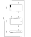
- FIG. 2 is the schematic which shows the external appearance of the smart phone of Embodiment 1.
- FIG. It is a schematic diagram which shows the state of the smart phone of Embodiment 1. It is a screen transition figure when holding the smart phone of Embodiment 1. It is a screen transition figure when not grasping the smart phone of Embodiment 1.
- It is a flowchart which shows the flow of a process of the smart phone of Embodiment 1.
- FIG. 2 shows the change of the lighting control information in the smart phone of Embodiment 2.
- FIG. 9 is a diagram illustrating a configuration of a detection unit of a smartphone according to Embodiments 3 to 7. It is a flowchart which shows the flow of a process of the smart phone of Embodiment 6.
- Embodiment 1 An embodiment of the present invention will be described below with reference to FIGS.
- the application example is not limited to a smartphone, and the present invention can be applied to any mobile terminal including a display unit that performs screen display.
- descriptions of configurations other than those described in the following specific embodiments may be omitted as necessary, but when described in other embodiments, the configurations are the same.
- members having the same functions as the members shown in each embodiment are given the same reference numerals, and the description thereof is omitted as appropriate.
- the shape of the configuration described in each drawing and the dimensions such as length, size, and width do not reflect the actual shape and dimensions, but are changed as appropriate for the sake of clarity and simplification of the drawings. is doing.
- FIG. 2 is a schematic diagram showing the appearance of the smartphone 1.
- the smartphone 1 according to the present embodiment includes a display unit 13 described later on at least one surface of the housing. In general, hereinafter, the surface including the display unit 13 is referred to as the “front” of the smartphone 1.
- the smartphone 1 according to the present embodiment includes a contact sensor 31 described later at a position where a user's hand holding the smartphone 1 contacts the smartphone 1.
- the smartphone 1 includes one contact sensor 31 on each of two surfaces (side surfaces) adjacent to the front long side.
- the position of the contact sensor 31 is not limited to this structure.
- the contact sensor 31 may be provided on the entire side surface.
- the number of contact sensors 31 is not limited to one for each side surface, and a plurality of contact sensors 31 may be provided for each side surface.
- FIGS. 3 is a schematic diagram illustrating a state of the smartphone 1
- FIG. 4 is a screen transition diagram when the smartphone 1 is gripped
- FIG. 5 is a screen transition diagram when the smartphone 1 is not gripped. It is.
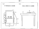
- FIG. 3 in the smartphone 1, (a) a state in which the user is holding with the hand H, and (b) a state in which the user is placed on the desk D (the user is not holding with the hand H). State).
- the state (a) the user is likely to be using the smartphone 1 and the display unit 13 should not be turned off.
- the display unit 13 is kept on. For example, as shown in FIG. 4A and FIG. 4B, when the display unit 13 is turned off, the contact sensor 31 is in contact with an object. Detect if there is any. Then, when it is determined based on the detection result that the hand is held by the user's hand, the lighting of the display unit 13 is maintained as shown in FIG.
- a display part 13 is turned on and off.
- the smartphone 1 maintains the lighting of the display unit 13 as illustrated in FIG.
- the smartphone 1 turns off the display unit 13 as illustrated in FIG.
- the state where the display unit 13 of the smartphone 1 is lit may be expressed as a lit state
- the state where the display unit 13 of the smartphone 1 is not lit (turned off) may be expressed as an unlit state.
- FIG. 1 is a block diagram illustrating an example of a main configuration of the smartphone 1.
- the smartphone 1 includes at least a control unit 10, a detection unit 11, an operation unit 12, a display unit 13, and a storage unit 14.
- the operation unit 12 accepts user input operations.
- the operation unit 12 includes a touch panel (not shown) integrated with the display unit 13 and a physical key (not shown).
- the operation unit 12 outputs the detection result of the touch panel to the operation control unit 21 described later.
- the user can cause the smartphone 1 to execute the application by bringing the indicator into contact with a predetermined position on the touch panel.
- the touch panel includes a contact sensor, and examples of the contact sensor include a pressure sensor, a capacitance sensor, and an optical sensor.
- the operation unit 12 outputs information indicating the input process to the operation control unit 21 described later. For example, the user can turn on or off the display unit 13 of the smartphone 1 by pressing a predetermined physical key.
- the display unit 13 displays information processed by the smartphone 1 as an image. Specifically, the display unit 13 displays an image by being turned on by a lighting control unit 24 described later. The display unit 13 displays information processed by a display control unit (not shown) as an image. Further, as described above, the display unit 13 and the operation unit 12 constitute a touch panel.
- the display unit 13 is configured by, for example, an LCD (liquid crystal display).
- the detection unit 11 detects the state of the smartphone 1. Specifically, the detection unit 11 according to the present embodiment includes a contact sensor 31 as shown in FIG. The detection unit 11 detects whether or not an object is in contact with the smartphone 1 using the contact sensor 31 and supplies a detection result to the detection control unit 22 described later.
- the contact sensor 31 is a sensor that detects contact of an object such as a user's hand.
- the contact sensor 31 is a capacitance sensor or a pressure sensor. Further, since the power consumption of the contact sensor 31 itself is low, for example, the contact sensor 31 can be always operated while the display unit 13 is lit or regardless of whether or not the display unit 13 is lit.
- the detection unit 11 may output the detection result to the detection control unit 22 when the detection result by the contact sensor 31 changes.
- the control unit 10 performs overall control of each unit included in the smartphone 1. As illustrated in FIG. 1, the control unit 10 includes an operation control unit 21, a detection control unit 22, an application identification unit 23, a lighting control unit 24, and an application execution unit 25.
- the operation control unit 21 refers to the information output from the operation unit 12, identifies the process executed on the smartphone 1, and outputs information indicating the identified process to each unit of the control unit 10. . Specifically, when the operation control unit 21 specifies the process of “lighting the display unit 13”, the operation control unit 21 outputs information (lighting process information) indicating the process of lighting the display unit 13 to the lighting control unit 24. When the operation control unit 21 specifies the “execute the selected application” process, the operation control unit 21 outputs information (execution information) indicating the process for causing the application execution unit 25 to execute the selected application.
- the lighting control unit (lighting control means) 24 controls lighting and extinguishing of the display unit 13.
- lighting of the display unit 13 indicates turning on of the LCD and / or backlight (not shown), and turning off of the display unit 13 indicates turning off of the LCD and / or backlight.
- lighting and extinguishing are not limited to the above definition as long as they control on / off of screen display for the user.
- the lighting control unit 24 acquires the lighting processing information from the operation control unit 21, the lighting control unit 24 lights the display unit 13.
- the lighting control unit 24 may turn on the display unit 13 and output information (lighting information) indicating that the display control unit 22 has turned on the display unit 13.
- the lighting control unit 24 is configured to display an application that displays a screen on the display unit 13 from the application specifying unit 23 ( Information for specifying (display application) (specific information) is acquired. Then, information (lighting control information) indicating whether the application is an application that maintains lighting of the display unit 13 and is associated with the acquired specific information is read from the condition storage unit 41 described later. If the read lighting control information indicates that the display unit 13 is turned off, the display unit 13 is turned off.
- the detection control part (contact determination means) 22 acquires a detection result from the detection part 11, and determines whether the smart phone 1 is hold
- the application specifying unit (application specifying unit) 23 specifies an application (display application) that is displaying a screen on the display unit 13. Specifically, when obtaining the determination result from the detection control unit 22, the application specifying unit 23 inquires the application execution unit 25 about the display application, specifies the display application from the result of the inquiry, and selects the display application. Create specific information to uniquely identify. Then, the application specifying unit 23 outputs the specifying information to the lighting control unit 24.
- the application execution unit 25 executes an application. Specifically, when acquiring the execution information from the operation control unit 21, the application execution unit 25 executes the application indicated by the execution information, instructs the display control unit (not shown), and causes the display unit 13 to execute the application. The screen display of the application is executed.
- the storage unit 14 stores various data used in the smartphone 1. As shown in FIG. 1, the storage unit 14 includes a condition storage unit 41.
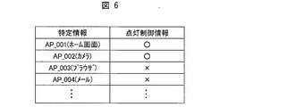
- the condition storage unit 41 stores the specific information and the lighting control information in association with each other. Specifically, the condition storage unit 41 stores a condition management table shown in FIG. Note that the data structure shown in FIG. 6 is an example, and the present invention is not limited to this example.
- the data structure shown in FIG. 6 is an example, and the present invention is not limited to this example.
- the specific information in FIG. 6 is composed of alphanumeric characters, but any information that can uniquely identify each application may be used.
- Whether or not the lighting control information stored in the “lighting control information” column is an application associated with lighting control information indicating that the application indicated by the specific information maintains lighting of the display unit 13 is determined. In other words, it indicates whether the application is associated with lighting control information indicating that the display unit 13 is turned off.
- “ ⁇ ” indicates that the application is associated with the lighting control information indicating that the display unit 13 is turned off, and “ ⁇ ” indicates that the display unit 13 is turned on. This indicates that the application is associated with the lighting control information indicating that it is to be maintained. Note that the lighting control information is not limited to this example as long as it can distinguish between an application that maintains lighting of the display unit 13 and an application that turns off the display unit 13.
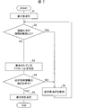
- FIG. 7 is a flowchart showing an example of the flow of the lighting control process.
- the detection control unit 22 acquires a detection result from the detection unit 11, and specifies whether or not the contact sensor 31 has detected contact (S2: contact determination step).
- S2 contact determination step
- the detection control unit 22 determines that the smartphone 1 is held by the user's hand.
- the lighting of the display unit 13 is maintained (S6), and the detection unit 11 detects the presence or absence of contact again (returns to S2).
- the detection control unit 22 determines that the smartphone 1 is not gripped by the user's hand. Then, the detection control unit 22 outputs the determination result to the application specifying unit 23.
- the detection control unit 22 continues to acquire the detection result from the detection unit 11 even after the determination result is output.
- the application specifying unit 23 inquires of the application execution unit 25 and specifies the display application (S3). Then, the application specifying unit 23 creates the specifying information and outputs it to the lighting control unit 24. Subsequently, the lighting control unit 24 that has acquired the specific information reads the lighting control information associated with the acquired specific information with reference to the condition storage unit 41, and the read lighting control information is displayed on the display unit 13. It is specified whether or not the information indicates light extinction (S4: lighting control step).
- the lighting control information does not indicate turning off, that is, when the lighting information is information indicating that the lighting of the display unit 13 is maintained (NO in S4), the lighting of the display unit 13 is maintained (S6). Then, the detection part 11 detects the presence or absence of a contact again (returning to S2). On the other hand, when the lighting information indicates light extinction (YES in S4), the lighting control unit 24 turns off the display unit 13 (S5), and the lighting control process ends.
- the smartphone 1 identifies the application that is displaying the screen on the display unit 13 even when the detection result of the contact sensor 31 determines that the user does not hold the smartphone 1. Then, the lighting and extinguishing of the display unit 13 can be controlled by specifying the lighting control information associated with the specified application. Therefore, even when the user is using the smartphone 1 without holding it (for example, when the smartphone 1 is placed on a desk and another operation is performed while viewing the screen), the display unit 13 is turned off. Can be prevented. On the other hand, when there is a high possibility that the smartphone 1 is not used, it can be appropriately turned off. As described above, power consumption can be reduced without impairing user convenience.
- FIG. 8 is a screen diagram showing the change of the lighting control information.
- a configuration for changing lighting control information by executing an application for setting (changing) lighting control information will be described. That is, the user can change the lighting control information by executing the application by performing a predetermined operation on the touch panel (contact sensor).
- a setting table 51 shown in FIG. 8 is displayed on the display unit 13 when the application is executed.
- information for example, application name
- the “light-off” column information indicating whether each application is an application that turns off the display unit 13, that is, lighting control information is displayed as a UI component.
- a mark “ ⁇ ” indicates an application that turns off the display unit 13
- a mark “X” indicates an application that maintains the lighting of the display unit 13.
- the UI component accepts an operation (for example, a flick operation performed at the position of the UI component) by an indicator (user's hand H) on the touch panel.
- the operation control unit 21 acquires information indicating the operation and outputs the information to a lighting control information changing unit (not shown). Then, the lighting control information changing unit changes the lighting control information stored in the condition storage unit 41. For example, when the lighting control information of the “home screen” is changed from “ ⁇ ” to “ ⁇ ” by the above operation as in the screen transition from FIG.
- the application on the home screen displays an image on the display unit 13 in the smartphone 1 that is not gripped by the hand, the display unit 13 is kept on.
- the user can freely set the case where the display screen is turned on and the case where the display screen is turned off according to the usage state of the application. Therefore, user convenience can be improved.
- the configuration of the second embodiment can also be applied to later-described third to sixth embodiments and modifications thereof.
- FIG. 9 is a block diagram illustrating an example of a main part configuration of the smartphone 2
- FIG. 12A is a diagram illustrating a configuration of the detection unit 15 of the smartphone 2 according to the third embodiment.
- the touch sensor 31 it is determined whether or not the touch sensor 31 is gripped by the user's hand. Since the processing load on the control unit 10 is light, a quick reaction can be achieved with low power consumption.
- the contact sensor 31 is a capacitance sensor, for example, when the martphone 1 is placed on a conductive metal desk, the contact sensor 31 reacts, and the detection control unit 22 is operated by the user's hand. There is a possibility that it may be determined that the object has been gripped.
- the contact sensor 31 is a pressure-sensitive sensor, the contact sensor 31 reacts if the object is in contact regardless of whether the object on the desk is conductive or not.
- the detection unit 15 of the smartphone 2 according to the third embodiment includes a sub sensor 32 in addition to the contact sensor 31. Further, as shown in FIG. 12A, the sub sensor 32 of the present embodiment includes a temperature sensor 33.
- the temperature sensor 33 is a sensor that is provided in the vicinity of the contact sensor 31 and detects the temperature around the temperature sensor. As the temperature sensor 33, an existing temperature sensor generally mounted on a smartphone or the like can be used. Further, when a detection result is requested from the detection control unit 26, the temperature sensor 33 outputs the detected temperature to the detection control unit 26.
- the temperature sensor 33 and the angular velocity sensor 34, the acceleration sensor 35, the proximity sensor 36, and the illuminance sensor 37 described in Embodiments 4 to 6 to be described later are supplied with power when the contact sensor 31 detects contact of an object. Although it is desirable that the power for operating each of the sensors other than the contact sensor 31 is supplied from (not shown), it is not limited to this configuration.
- the detection control unit 26 acquires information (detection result) indicating whether or not the contact sensor 31 has detected contact of an object from the detection unit 15, and the detection result indicates that the contact sensor 31 has detected contact of an object.
- the temperature of the object (detected temperature) detected by the temperature sensor 33 is further acquired from the detection unit 15.
- the detection control part 26 is the smart phone 2 when the detection temperature is a temperature within a predetermined range, that is, a temperature assumed to be detected when the user holds the smart phone 2 (assumed temperature). Is held by the user's hand.
- the detection control unit 26 determines that an object other than the user's hand has contacted the contact sensor 31, that is, the smartphone 2 is not gripped by the user's hand.
- the detection control unit 26 may be configured to determine whether or not a temperature change due to contact with an object is within a predetermined range. For example, the detection control unit 26 detects the temperature (first temperature) when the temperature sensor 33 is operated and the temperature (second temperature) when a predetermined time (for example, 1 second) has elapsed since the first temperature measurement. And get.
- the detection control part 26 pinpoints the temperature change between the said 1st temperature and the said 2nd temperature, and the smart phone 2 is hold
- the detection control part 26 acquires the detection result of the contact sensor 31 from the detection part 15, and specifies whether the contact sensor 31 detected the contact (S2).
- the detection control unit 26 acquires the detection result of the temperature sensor 33 from the detection unit 15, and the detected temperature detected in the contact is within a predetermined range. It is specified whether or not the temperature is (S7).
- the detection control unit 26 determines that the smartphone 2 is held by the user's hand. As a result, the lighting of the display unit 13 is maintained (S6), and the detection unit 11 detects the presence or absence of contact again (returns to S2). On the other hand, when the detected temperature is outside the predetermined range (NO in S7), the detection control unit 26 determines that the smartphone 2 is not gripped by the user's hand. Then, the detection control unit 26 outputs the determination result to the application specifying unit 23.
- FIG. 12B is a diagram illustrating a configuration of the detection unit 15 of the smartphone 2 according to the fourth embodiment.
- the sub sensor 32 of the fourth embodiment includes an angular velocity sensor (Gyro sensor) 34.
- the angular velocity sensor 34 is a sensor that detects the tilt of the smartphone.
- an existing angular velocity sensor generally mounted on a smartphone or the like can be used. Specifically, when the angular velocity sensor 34 is requested by the detection control unit 26 to detect the angular velocity, the angular velocity sensor 34 detects the angle (tilt) of the smartphone with respect to the horizontal axis, and the detected angle is sent to the detection control unit 26. Output.
- the detection control unit 26 acquires information (detection result) indicating whether or not the contact sensor 31 has detected contact of an object from the detection unit 15, and the detection result indicates that the contact sensor 31 has detected contact of an object.
- the angle of the smartphone 2 detected by the angular velocity sensor 34 is further acquired from the detection unit 15. And when the acquired angle is an angle that coincides with the angle when the smartphone 2 is placed on a horizontal plane, specifically, an angle in the range of 0 degrees to 20 degrees (or 180 degrees to 160 degrees), It determines with the smart phone 2 not being hold
- the range of the said angle is an example, and is not limited to this example.
- the smartphone 2 is gripped by the user's hand.
- the above determination condition is an example. For example, when the angle of the smartphone 2 is 25 degrees to 75 degrees, it is determined that the smartphone 2 is held by the user's hand, and the angle is outside this range. It may be determined that the smartphone 2 is not gripped by the user's hand.
- the detection control unit 26 determines that the smartphone 2 is not gripped by the user's hand, the determination result is output to the application specifying unit 23.
- FIG. 12C is a diagram illustrating a configuration of the detection unit 15 of the smartphone 2 according to the fifth embodiment.
- the sub sensor 32 of the smartphone 2 includes an acceleration sensor 35.
- the acceleration sensor 35 is a sensor that detects acceleration generated in the smartphone 2, that is, whether the housing of the smartphone 2 is moving.
- an existing acceleration sensor generally mounted on a smartphone or the like can be used. Specifically, when the acceleration sensor 35 is requested by the detection control unit 26 to detect an acceleration detection result, the acceleration sensor 35 detects the presence or absence of acceleration in the smartphone 2 and detects information indicating the presence or absence of acceleration (acceleration information). Output to.
- the detection control unit 26 further acquires the acceleration information detected by the acceleration sensor 35 from the detection unit 15 when the detection result of the contact sensor 31 indicates that the contact of the object has been detected. And when the said acceleration information has shown that the acceleration has generate
- the detection control unit 26 may be configured to acquire an acceleration value from the acceleration sensor 35. In this case, whether or not the smartphone 2 is held by the user's hand may be determined based on whether or not the acquired acceleration value is within a predetermined range.
- the detection control part 26 acquires the detection result of the contact sensor 31 from the detection part 15, and specifies whether the contact sensor 31 detected the contact (S2).
- the detection control unit 26 acquires, from the detection unit 15, the detection result of the acceleration sensor 35, specifically acceleration information indicating the presence or absence of acceleration, It is specified whether or not the smartphone 2 is in a stationary state (S8).
- the detection control unit 26 determines that the smartphone 2 is held by the user's hand. As a result, the lighting of the display unit 13 is maintained (S6), and the detection unit 11 detects the presence or absence of contact again (returns to S2).
- the detection control unit 26 determines that the smartphone 2 is not gripped by the user's hand. Then, the detection control unit 26 outputs the determination result to the application specifying unit 23.
- the smartphone 2 according to the third to fifth embodiments is gripped by the user's hand based on the combination of the detection result of the contact sensor 31 and the detection result of the temperature sensor 33, the angular velocity sensor 34, or the acceleration sensor 35. It is determined whether or not. Therefore, as compared with the smartphone 1 described in the first and second embodiments, it can be more accurately determined whether or not the user is gripped by the user's hand, so that the possibility of erroneous detection can be reduced.
- the temperature sensor 33, the angular velocity sensor 34, or the acceleration sensor that is generally installed in a smartphone is used, a more reliable means for determining contact by hand without adding new parts and functions. Can be realized.
- FIG. 12D is a figure which shows the structure of the detection part 15 of the smart phone 2 of Embodiment 5. As shown in FIG. 12D and FIG. (D) of FIG. 12 is a figure which shows the structure of the detection part 15 of the smart phone 2 of Embodiment 5. As shown in FIG. 12D and FIG. (D) of FIG. 12 is a figure which shows the structure of the detection part 15 of the smart phone 2 of Embodiment 5. As shown in FIG.
- the sub sensor 32 of the smartphone 2 according to the sixth embodiment includes the angular velocity sensor 34 and the acceleration sensor 35 described above.
- the detection control unit 26 indicates that the detection result of the contact sensor 31 has detected the contact of an object, and the detection result of the angular velocity sensor 34 is an angle that matches the angle when the smartphone 2 is placed on a horizontal plane.
- the acceleration information detected by the acceleration sensor 35 is further acquired from the detection unit 15.
- the said acceleration information has shown that the acceleration has generate
- the said acceleration information has shown that the acceleration has not generate
- the detection control unit 26 may be configured to acquire an acceleration value from the acceleration sensor 35. In this case, whether or not the smartphone 2 is held by the user's hand may be determined based on whether or not the acquired acceleration value is within a predetermined range.
- the detection control part 26 acquires the detection result of the contact sensor 31 from the detection part 15, and specifies whether the contact sensor 31 detected the contact (S2).
- the detection control unit 26 acquires the detection result of the angular velocity sensor 34 from the detection unit 15, and the posture of the smartphone 2 is placed on a horizontal plane. Is identified (S9).
- the detection control unit 26 determines that the smartphone 2 is held by the user's hand. As a result, the lighting of the display unit 13 is maintained (S6), and the detection unit 11 detects the presence or absence of contact again (returns to S2).
- the detection control unit 26 detects the detection result of the acceleration sensor 35, specifically the presence or absence of acceleration, from the detection unit 15.
- the acceleration information shown is acquired, and it is specified whether the smart phone 2 is in a stationary state (S10).
- the detection control unit 26 determines that the smartphone 2 is held by the user's hand. As a result, the lighting of the display unit 13 is maintained (S6), and the detection unit 11 detects the presence or absence of contact again (returns to S2).
- the detection control unit 26 determines that the smartphone 2 is not gripped by the user's hand. Then, the detection control unit 26 outputs the determination result to the application specifying unit 23.
- the smartphone 2 determines whether or not the smartphone 2 is being held by the user's hand based on the detection results of the three types of sensors. Therefore, the possibility of erroneous detection can be further reduced as compared with the case where two types of sensors described in the third to fifth embodiments are used. As a result, the convenience for the user can be further improved as compared with the case of using two types of sensors.
- the angular velocity sensor and the angular velocity sensor that are generally installed in smartphones are used, it is possible to realize a more reliable means for determining contact by hand without adding new parts and functions. .
- the sub sensor 32 of the smartphone 2 includes the various sensors described above (the temperature sensor 33, the angular velocity sensor 34, and the acceleration sensor 35). Further, the sub sensor 32 may include various sensors that are generally mounted on a smartphone, such as the proximity sensor 36 and the illuminance sensor 37, in addition to the various sensors described above.
- the detection control unit 26 further acquires the detection results of the various sensors other than the contact sensor 31 from the detection unit 15 when the detection result of the contact sensor 31 indicates that the contact of the object has been detected. And it is determined whether the smart phone 2 is hold
- the determination conditions of the detection results of the various sensors and information indicating whether or not the sensor is held by the user's hand are stored in the storage unit 14 in association with each other.
- the smartphone 2 may be determined not to be held by the user's hand.
- the above-mentioned specific example is an example, and determination of whether the smart phone 2 is hold
- the smartphones 1 and 2 of the first to seventh embodiments are lit unless the display application that is displaying the screen on the display unit 13 is changed to an application associated with the lighting control information indicating that the display unit 13 is turned off. It was a configuration to maintain.
- the smartphones 1 and 2 are not limited to the above configuration.
- a timer (not shown) that measures the lighting time of the display unit 13 may be provided, and the display unit 13 may be turned off when the lighting time exceeds a predetermined value.
- the predetermined value may be set by the user operating the operation unit 12, or may be set to a different value depending on each application.
- the user may be able to select whether or not to turn off the display unit 13 when the lighting time exceeds a predetermined value.
- the smartphones 1 and 2 of the first to seventh embodiments may include a plurality of applications (display applications) that perform screen display on the display unit 13.
- the lighting control unit 24 reads the lighting control information associated with each display application, and when all of the read lighting control information is lighting control information indicating that the display unit 13 is turned off, the display unit 13 may be turned off. Further, the lighting control unit 24 reads only the lighting control information of the active application, and when the read lighting control information is lighting control information indicating that the display unit 13 is turned off, even if the display unit 13 is turned off. Good.
- the control blocks (especially the operation control unit 21, the detection control units 22 and 26, the application specifying unit 23, the lighting control unit 24, and the application execution unit 25) of the smartphones 1 and 2 are formed in an integrated circuit (IC chip) or the like. It may be realized by a logic circuit (hardware), or may be realized by software using a CPU (Central Processing Unit). In the latter case, the smartphones 1 and 2 include a CPU that executes instructions of a program that is software that realizes each function, and a ROM (Read Only Memory) in which the program and various data are recorded so as to be readable by the computer (or CPU).
- IC chip integrated circuit
- CPU Central Processing Unit
- a storage device (these are referred to as “recording media”), a RAM (Random Access Memory) for expanding the program, and the like are provided.
- the objective of this invention is achieved when a computer (or CPU) reads the said program from the said recording medium and runs it.
- a “non-temporary tangible medium” such as a tape, a disk, a card, a semiconductor memory, a programmable logic circuit, or the like can be used.
- the program may be supplied to the computer via an arbitrary transmission medium (such as a communication network or a broadcast wave) that can transmit the program.
- the present invention can also be realized in the form of a data signal embedded in a carrier wave in which the program is embodied by electronic transmission.
- a mobile terminal (smartphones 1 and 2) according to aspect 1 of the present invention includes a display unit (13) that is turned on or off, and a detection unit (11) that includes a contact sensor (31) provided in a housing.
- a contact determination unit (detection control unit 22) for determining contact based on a detection result of the detection unit, and a lighting control unit (lighting control unit 24) for controlling lighting and extinction of the display unit,
- the lighting control unit controls lighting and extinguishing of the display unit according to the content of the screen display on the display unit when the contact determination unit determines that there is no contact.
- the user may be using the mobile terminal even if he / she is not holding the mobile terminal (for example, performing another work while viewing the screen by placing the mobile terminal on the desk). Even in such a case, since the lighting and extinguishing of the display unit are controlled according to the contents of the screen display as described above, the display unit is turned off when the user is highly likely to use the terminal. The situation can be prevented. On the other hand, when there is a high possibility that the mobile terminal is not used, it can be appropriately turned off. As described above, the power consumption can be reduced without impairing the convenience of the user to use.
- a mobile terminal (smartphones 1 and 2) according to aspect 2 of the present invention includes a display unit (13) that is turned on or turned off, and a detection unit (11) that includes a contact sensor (31) provided in a housing.
- a contact determination unit (detection control unit 22) for determining contact based on a detection result of the detection unit, and a lighting control unit (lighting control unit 24) for controlling lighting and extinction of the display unit,
- the lighting control unit controls lighting and extinguishing of the display unit according to an application being executed in the terminal when the contact determining unit determines that there is no contact.
- the mobile terminal according to aspect 3 of the present invention further includes an operation unit (12) that receives a user operation in the above-described aspect 2, and specifies specific information for identifying an application that can be executed on the terminal and lighting of the display unit.
- the lighting control information indicating whether or not to maintain may be changeable according to the above operation.
- the lighting control information associated with the specific information can be changed.
- the user can freely set a case where the display screen is kept on and a case where the display screen is turned off according to the usage state of the mobile terminal. Therefore, user convenience can be improved.
- the mobile terminal according to aspect 4 of the present invention is the mobile terminal according to aspects 1 to 3, wherein the contact determination means detects that the user touches the terminal when the contact sensor does not detect contact of an object in the detection unit. It may be determined that there is not.
- the contact determination means detects the contact of the object with the contact sensor, and at least one of the following (1) to (4): When one condition is satisfied, it may be determined that there is no contact by the user.
- the temperature sensor (33) included in the detection unit detects a temperature outside the range that is assumed to be detected when the user holds the terminal.
- the angular velocity sensor (34) included in the detection unit detects that the posture of the terminal matches the posture when placed on a horizontal plane.
- the acceleration sensor (35) included in the detection unit detects that the terminal is stationary.
- the angular velocity sensor included in the detection unit detects that the posture of the terminal matches the posture when the terminal is placed on a horizontal plane, and the acceleration sensor included in the detection unit detects that the terminal is stationary. Detect that it is in a state.
- various sensors are used in addition to the contact sensor.
- a temperature sensor angular velocity sensor, or acceleration sensor
- a mobile terminal control method is a mobile terminal control method including a display unit that is turned on or off, and sensor detection in a detection unit including a contact sensor provided in a housing.
- the display unit is turned on and off according to the content of the screen display on the display unit. Lighting control step (S4) to control.
- the mobile terminal according to each aspect of the present invention may be realized by a computer.
- the mobile terminal is realized by the computer by causing the computer to operate as each unit included in the mobile terminal.
- a control program and a computer-readable recording medium on which the control program is recorded also fall within the scope of the present invention.
- the present invention can also be expressed as follows.
- the mobile terminals are mobile terminals including a display unit (13) that performs screen display, and are provided at positions where the user's hand holding the housing comes into contact.
- a detection unit (11) including at least a contact sensor (31), contact determination means (detection control unit 22) for determining presence or absence of contact by a user's hand based on a detection result of the sensor in the detection unit, and the contact determination
- lighting control means lighting control unit 24 that controls lighting and extinguishing of the display unit according to the content of the screen display on the display unit is provided.
- the portable terminal which concerns on aspect 8 of this invention is matching with the lighting control information which shows whether the specific information which identifies the application which can be performed on an own terminal in the said aspect 7, and the lighting of the said display part is maintained.
- application specifying means application specifying unit 23
- the display unit may be turned on and off in accordance with the above definition.
- the mobile terminal according to aspect 9 of the present invention may further include an operation unit (12) for receiving the user's operation in the aspect 8, and the lighting control information may be changed according to the operation.
- the mobile terminal according to aspect 10 of the present invention is the mobile terminal according to aspects 7 to 9, wherein the contact determination unit is configured to detect the contact of the user with the user's hand when the contact sensor does not detect the object contact in the detection unit. It may be determined that there is no contact due to.
- the contact determination means detects the contact of the object with the contact sensor, and at least one of the following (1) to (4): When one condition is satisfied, it may be determined that there is no contact by the user's hand.
- the temperature sensor (33) included in the detection unit detects a temperature outside the range that is assumed to be detected when the user holds the terminal.
- the angular velocity sensor (34) included in the detection unit detects that the posture of the terminal matches the posture when placed on a horizontal plane.
- the acceleration sensor (35) included in the detection unit detects that the terminal is stationary.
- the angular velocity sensor included in the detection unit detects that the posture of the terminal matches the posture when the terminal is placed on a horizontal plane, and the acceleration sensor included in the detection unit detects that the terminal is stationary. Detect that it is in a state.
- a control method for a mobile terminal is a control method for a mobile terminal including a display unit that performs screen display, and includes a contact sensor provided at a position where a user's hand holding the casing comes into contact.
- a contact determination step (S2) for determining presence or absence of contact by a user's hand based on a detection result of a sensor in at least the detection unit, and the display unit when the contact determination step determines that there is no contact by the hand
- a lighting control step for controlling lighting and extinguishing of the display unit according to the contents of the screen display.
- the present invention can be used for a portable terminal including a display unit that performs screen display.
Landscapes
- Engineering & Computer Science (AREA)
- Signal Processing (AREA)
- Physics & Mathematics (AREA)
- Computer Hardware Design (AREA)
- General Physics & Mathematics (AREA)
- Theoretical Computer Science (AREA)
- Computer Networks & Wireless Communication (AREA)
- Telephone Function (AREA)
Abstract
筐体に設けられた接触センサ(31)の検知結果に基づいて接触を判定する検知制御部(22)と、表示部の点灯および消灯を制御する点灯制御部(24)と、を備え、上記点灯制御部(24)は、接触がないと判定された場合、表示部(13)における画面表示の内容に応じて、上記表示部(13)の点灯および消灯を制御する。
Description
本発明は画面表示を行う表示部を備える携帯端末に関する。
従来、携帯端末の表示部において、消費電力節減のために、点灯されてから所定時間操作がなされなかった場合に消灯されるという技術がある。しかしながら、上記技術では、ユーザが表示部に表示された情報を閲覧していたとしても、所定時間操作がされなければ、表示部が消灯されてしまう。この場合、ユーザは改めて表示部を点灯させるための操作を行わなければならず、ユーザにとって不便であるという問題があった。
この問題に対して、下記特許文献1には、携帯端末に温度センサを備え、ユーザが携帯端末を把持しているときの筐体の温度と、把持していないときの筐体の温度との間における温度変化を検出し、ユーザが携帯端末を把持したときに表示部を点灯させ、ユーザが携帯端末を手放した時に表示部を消灯させる技術が開示されている。
ところで、ユーザが携帯端末を把持せずに使用する(例えば携帯端末を机上に置いて画面を見ながら別の作業を行う)という状況もある。しかしながら、上記特許文献1に開示された技術は、携帯端末を手放したときに表示部が消灯されるため、ユーザは、携帯端末を把持せずに使用することができない。つまり、上記特許文献1に開示された技術には、携帯端末を使用するユーザの不便を解消するには十分でないという課題がある。
本発明は、上記課題を解決するためになされたものであり、その目的は、状況に応じて適切に消灯することで、使用するユーザの利便性を損なうことなく消費電力を節減することができる携帯端末などを提供することにある。
上記の課題を解決するために、本発明の一態様に係る携帯端末は、点灯状態または消灯状態となる表示部と、筐体に設けられた接触センサを含む検知部と、上記検知部の検知結果に基づいて接触を判定する接触判定手段と、上記表示部の点灯および消灯を制御する点灯制御手段と、を備え、上記点灯制御手段は、上記接触判定手段によって接触がないと判定された場合、上記表示部における画面表示の内容に応じて、上記表示部の点灯および消灯を制御する。
また、上記の課題を解決するために、本発明の一態様に係る携帯端末は、点灯状態または消灯状態となる表示部と、筐体に設けられた接触センサを含む検知部と、上記検知部の検知結果に基づいて接触を判定する接触判定手段と、上記表示部の点灯および消灯を制御する点灯制御手段と、を備え、上記点灯制御手段は、上記接触判定手段によって接触がないと判定された場合、自端末において実行されているアプリケーションに応じて、上記表示部の点灯および消灯を制御する。
本発明の一態様によれば、状況に応じて適切に消灯することで、使用するユーザの利便性を損なうことなく消費電力を節減することができる携帯端末などを提供できるという効果を奏する。
〔実施形態1〕
本発明の一実施形態について、図1~図7に基づいて説明すれば、以下のとおりである。本実施形態では、本発明をスマートフォン1に適用した例を説明する。なお、適用例はスマートフォンに限定されず、画面表示を行う表示部を備える携帯端末であれば本発明を適用可能である。また、以下の特定の実施形態で説明する構成以外の構成については、必要に応じて説明を省略する場合があるが、他の実施形態で説明されている場合は、その構成と同じである。さらに、説明の便宜上、各実施形態に示した部材と同一の機能を有する部材については、同一の符号を付し、適宜その説明を省略する。また、各図面に記載した構成の形状、ならびに、長さ、大きさおよび幅などの寸法は、実際の形状や寸法を反映させたものではなく、図面の明瞭化と簡略化のために適宜変更している。
本発明の一実施形態について、図1~図7に基づいて説明すれば、以下のとおりである。本実施形態では、本発明をスマートフォン1に適用した例を説明する。なお、適用例はスマートフォンに限定されず、画面表示を行う表示部を備える携帯端末であれば本発明を適用可能である。また、以下の特定の実施形態で説明する構成以外の構成については、必要に応じて説明を省略する場合があるが、他の実施形態で説明されている場合は、その構成と同じである。さらに、説明の便宜上、各実施形態に示した部材と同一の機能を有する部材については、同一の符号を付し、適宜その説明を省略する。また、各図面に記載した構成の形状、ならびに、長さ、大きさおよび幅などの寸法は、実際の形状や寸法を反映させたものではなく、図面の明瞭化と簡略化のために適宜変更している。
(スマートフォンの外観構成)
次に、図2を参照して、スマートフォン1の外観構成について説明する。図2は、スマートフォン1の外観を示す概略図である。本実施形態に係るスマートフォン1は、筐体の少なくとも1つの面に、後述する表示部13を備えている。一般的に、なお、以降、表示部13を備える面を、スマートフォン1の「正面」と呼称する。また、本実施形態に係るスマートフォン1は、スマートフォン1を把持するユーザの手がスマートフォン1に接触する位置に、後述する接触センサ31を備えている。例えば、図2に示すように、スマートフォン1は、上記正面の長辺と隣接する2つの面(側面)に、それぞれ1つずつの接触センサ31を備えている。なお、図2に示す接触センサ31は、上記側面の一部に備えられているが、接触センサ31の位置はこの構成に限定されない。例えば、接触センサ31が上記側面全体に備えられていてもよい。また、接触センサ31の数は、上記各側面に1つずつに限定されず、上記各側面に複数備えられていてもよい。
次に、図2を参照して、スマートフォン1の外観構成について説明する。図2は、スマートフォン1の外観を示す概略図である。本実施形態に係るスマートフォン1は、筐体の少なくとも1つの面に、後述する表示部13を備えている。一般的に、なお、以降、表示部13を備える面を、スマートフォン1の「正面」と呼称する。また、本実施形態に係るスマートフォン1は、スマートフォン1を把持するユーザの手がスマートフォン1に接触する位置に、後述する接触センサ31を備えている。例えば、図2に示すように、スマートフォン1は、上記正面の長辺と隣接する2つの面(側面)に、それぞれ1つずつの接触センサ31を備えている。なお、図2に示す接触センサ31は、上記側面の一部に備えられているが、接触センサ31の位置はこの構成に限定されない。例えば、接触センサ31が上記側面全体に備えられていてもよい。また、接触センサ31の数は、上記各側面に1つずつに限定されず、上記各側面に複数備えられていてもよい。
(スマートフォンの機能概要)
次に図3~図5を参照して、スマートフォン1の機能概要について説明する。図3は、スマートフォン1の状態を示す模式図であり、図4は、スマートフォン1を把持しているときの画面遷移図であり、図5は、スマートフォン1を把持していないときの画面遷移図である。図3に示すように、スマートフォン1においては、(a)ユーザが手Hで把持している状態と、(b)机Dの上などに置いている状態(ユーザが手Hで把持していない状態)と、が考えられる。上記(a)の状態の場合、ユーザはスマートフォン1を使用している可能性が高く、表示部13を消灯するべきではない。一方、上記(b)の場合、ただ置いているだけ(使用していない)の可能性と、置いて使用している(例えば、机D上に置いて画面を見ながら別の作業を行っている)可能性とが考えられる。前者の場合、消費電力の節減のためには、速やかに表示部13を消灯することが望ましいが、後者であった場合は、上記(a)の状態と同様に、表示部13を消灯するべきではない。
次に図3~図5を参照して、スマートフォン1の機能概要について説明する。図3は、スマートフォン1の状態を示す模式図であり、図4は、スマートフォン1を把持しているときの画面遷移図であり、図5は、スマートフォン1を把持していないときの画面遷移図である。図3に示すように、スマートフォン1においては、(a)ユーザが手Hで把持している状態と、(b)机Dの上などに置いている状態(ユーザが手Hで把持していない状態)と、が考えられる。上記(a)の状態の場合、ユーザはスマートフォン1を使用している可能性が高く、表示部13を消灯するべきではない。一方、上記(b)の場合、ただ置いているだけ(使用していない)の可能性と、置いて使用している(例えば、机D上に置いて画面を見ながら別の作業を行っている)可能性とが考えられる。前者の場合、消費電力の節減のためには、速やかに表示部13を消灯することが望ましいが、後者であった場合は、上記(a)の状態と同様に、表示部13を消灯するべきではない。
そこで、本実施形態に係るスマートフォン1は、接触センサ31の検知結果に基づいて、ユーザの手によって把持されていると判定される場合は、表示部13の点灯を維持する。例えば、図4の(a)および図4の(b)に示すように、表示部13が消灯されている状態から、点灯されている状態になったとき、接触センサ31に、物体の接触があるか否かを検知する。そして、この検知結果に基づいて、ユーザの手によって把持されていると判定される場合は、図4の(c)に示すように表示部13の点灯を維持する。
また、本実施形態に係るスマートフォン1は、接触センサ31の検知結果に基づいて、ユーザの手によって把持されていないと判定される場合は、表示部13における画面表示の内容に応じて、表示部13の点灯および消灯を制御する。例えば、ユーザの手によって把持されていないと判定されたとき、図5の(a)に示すように、ブラウザが表示されている場合は、ユーザがスマートフォン1を置いて使用している可能性が高いと考えられる。そのため、スマートフォン1は、図5の(b)に示すように、表示部13の点灯を維持する。一方、図5の(c)に示すように、ホーム画面が表示されている場合は、ユーザがスマートフォン1を使用していない可能性が高いと考えられる。そのため、スマートフォン1は、図5の(d)に示すように、表示部13を消灯する。
以上より、ユーザがスマートフォン1を把持していない場合でも、ユーザがスマートフォン1を使用している可能性が高い場合において、表示部が消灯されるという状況を防ぐことができる。また、その一方で、ユーザがスマートフォン1を使用していない可能性が高い場合は、適切に消灯することができる。よって、ユーザがスマートフォン1を把持していない場合でも、ユーザの利便性を損なうことなく消費電力を節減することができる。なお、スマートフォン1の表示部13が点灯している状態を点灯状態、スマートフォン1の表示部13が点灯していない(消灯している)状態を消灯状態と表現してもよい。
(スマートフォンの構成)
次に、図1および図6を参照して、スマートフォン1の要部構成について説明する。図1は、スマートフォン1の要部構成の一例を示すブロック図である。図1に示すように、スマートフォン1は少なくとも、制御部10、検知部11、操作部12、表示部13、および記憶部14を備えている。
次に、図1および図6を参照して、スマートフォン1の要部構成について説明する。図1は、スマートフォン1の要部構成の一例を示すブロック図である。図1に示すように、スマートフォン1は少なくとも、制御部10、検知部11、操作部12、表示部13、および記憶部14を備えている。
操作部12は、ユーザの入力操作を受け付ける。本実施形態では、操作部12は、表示部13と一体となっているタッチパネル(不図示)と、物理キー(不図示)とを含む。操作部12は、タッチパネルの検知結果を、後述する操作制御部21に出力する。例えば、ユーザはタッチパネルの所定の位置に指示体を接触させることで、スマートフォン1にアプリケーションを実行させることができる。なお、タッチパネルは接触センサを含み、上記接触センサとしては、圧力センサ、静電容量センサ、光センサなどが挙げられる。また、操作部12は、物理キーが押下される入力処理が行われたとき、当該入力処理を示す情報を、後述する操作制御部21に出力する。例えば、ユーザは所定の物理キーを押下することで、スマートフォン1の表示部13を点灯または消灯させることができる。
表示部13は、スマートフォン1にて処理される情報を画像として表示する。具体的には、表示部13は後述する点灯制御部24によって点灯されることで画像を表示する。また、表示部13は、表示制御部(不図示)などによって処理された情報を画像として表示する。さらに、上述したように、表示部13は操作部12と一体となってタッチパネルを構成している。表示部13は、例えばLCD(液晶ディスプレイ)などで構成される。
検知部11は、スマートフォン1の状態を検知する。具体的には、本実施形態に係る検知部11は、図1に示すように、接触センサ31を含む。検知部11は、接触センサ31を用いてスマートフォン1に物体が接触しているか否かを検知し、後述する検知制御部22に検知結果を供給する。接触センサ31は、上述したように、ユーザの手などの物体の接触を検知するセンサである。接触センサ31は、具体的には静電容量センサ、または感圧センサである。また、接触センサ31自体の消費電力が低いため、例えば、表示部13が点灯している間、または表示部13の点灯の有無に関わらず、接触センサ31を常に動作させることも可能である。なお、検知部11は、接触センサ31による検知結果が変化したときに、検知制御部22に検知結果を出力してもよい。
制御部10は、スマートフォン1が備える各部を統括制御する。制御部10は、図1に示すように、操作制御部21、検知制御部22、アプリケーション特定部23、点灯制御部24、およびアプリケーション実行部25を含む。
操作制御部21は、操作部12から出力される情報を参照して、スマートフォン1にて実行される処理を特定し、制御部10の各部に、特定した処理を示す情報を出力するものである。具体的には、操作制御部21は、「表示部13を点灯させる」処理を特定すると、点灯制御部24に表示部13を点灯させる処理を示す情報(点灯処理情報)を出力する。また、操作制御部21は、「選択されたアプリケーションを実行する」処理を特定すると、アプリケーション実行部25に選択されたアプリケーションを実行させる処理を示す情報(実行情報)を出力する。
点灯制御部(点灯制御手段)24は、表示部13の点灯および消灯を制御するものである。本実施形態では、表示部13の点灯とは上記LCDおよび/またはバックライト(不図示)の点灯を示し、表示部13の消灯とは、上記LCDおよび/またはバックライトの消灯を示す。しかしながら、点灯および消灯は、ユーザに対する画面表示のオン/オフを制御するものであればよく、上記の定義に限定されるものではない。具体的には、点灯制御部24は、操作制御部21から上記点灯処理情報を取得すると、表示部13を点灯させる。また、点灯制御部24は、表示部13を点灯させるとともに、検知制御部22に表示部13を点灯させた旨を示す情報(点灯情報)を出力してもよい。さらに、検知制御部22によって、スマートフォン1がユーザの手によって把持されていないと判定されたとき、点灯制御部24は、アプリケーション特定部23から、表示部13にて画面表示を行っているアプリケーション(表示アプリケーション)を特定するための情報(特定情報)を取得する。そして、後述する条件格納部41から、取得した上記特定情報と対応付けられている、アプリケーションが表示部13の点灯を維持するアプリケーションであるか否かを示す情報(点灯制御情報)を読み出す。そして、読み出した上記点灯制御情報が、表示部13の消灯を示すものであった場合、表示部13を消灯する。
検知制御部(接触判定手段)22は、検知部11から検知結果を取得し、当該検知結果からスマートフォン1がユーザの手によって把持されているか否かを判定するものである。例えば、検知制御部22は、点灯制御部24から上記点灯情報を取得したことをトリガとして、検知部11から検知結果、すなわち接触センサ31が物体の接触を検知したか否かを示す情報を取得する。本実施形態では、検知制御部22は、物体の接触を検知したことを示す情報を取得したとき、スマートフォン1がユーザの手によって把持されていると判定する。一方、物体の接触を検知していないことを示す情報を取得したとき、スマートフォン1がユーザの手によって把持されていないと判定する。また、検知制御部22は、スマートフォン1がユーザの手によって把持されていないと判定したとき、当該判定結果をアプリケーション特定部23に出力する。
アプリケーション特定部(アプリケーション特定手段)23は、表示部13にて画面表示を行っているアプリケーション(表示アプリケーション)を特定するものである。具体的には、アプリケーション特定部23は、検知制御部22から判定結果を取得すると、アプリケーション実行部25に上記表示アプリケーションを問い合わせて、上記問合せの結果から上記表示アプリケーションを特定し、上記表示アプリケーションを一意に特定するための特定情報を作成する。そして、アプリケーション特定部23は、点灯制御部24に上記特定情報を出力する。
最後に、アプリケーション実行部25は、アプリケーションを実行するものである。具体的には、アプリケーション実行部25は、操作制御部21から上記実行情報を取得すると、上記実行情報が示すアプリケーションを実行し、表示制御部(不図示)に指示して、表示部13にて当該アプリケーションの画面表示を実行させる。
記憶部14は、スマートフォン1にて使用される各種データを記憶する。図1に示すように、記憶部14は、条件格納部41を含む。
条件格納部41は、上記特定情報と上記点灯制御情報とを対応付けて格納している。具体的には、条件格納部41には、図6に示す条件管理テーブルが格納されている。なお、図6に示すデータ構造は一例であり、この例に限定されない。「特定情報」のカラムには、スマートフォン1で実行可能な各アプリケーションを一意に識別するための情報が格納される。図6の特定情報は英数字で構成されているが、上記各アプリケーションを一意に識別できる情報であればよい。「点灯制御情報」のカラムに格納されている点灯制御情報は、上記特定情報で示されるアプリケーションが、表示部13の点灯を維持することを示す点灯制御情報と対応付けられたアプリケーションであるか否か、換言すれば、表示部13を消灯することを示す点灯制御情報と対応付けられたアプリケーションであるか否かを示す。図6の例では、「○」の印にて表示部13を消灯することを示す点灯制御情報と対応付けられたアプリケーションであることを示し、「×」の印にて表示部13の点灯を維持することを示す点灯制御情報と対応付けられたアプリケーションであることを示している。なお、点灯制御情報は、表示部13の点灯を維持するアプリケーションと、表示部13を消灯するアプリケーションとを識別できるようになっていればよく、この例に限定されない。
(点灯制御処理の流れ)
次に、スマートフォン1が実行する点灯制御処理の流れの一例について、図7を参照して説明する。図7は、上記点灯制御処理の流れの一例を示すフローチャートである。
次に、スマートフォン1が実行する点灯制御処理の流れの一例について、図7を参照して説明する。図7は、上記点灯制御処理の流れの一例を示すフローチャートである。
表示部13が点灯したとき(S1)、検知制御部22は、検知部11から検知結果を取得し、接触センサ31が接触を検知したか否かを特定する(S2:接触判定ステップ)。接触センサ31が接触を検知していた場合(S2でYES)、検知制御部22は、スマートフォン1がユーザの手によって把持されていると判定する。その結果、表示部13の点灯は維持され(S6)、検知部11は、再び接触の有無を検知する(S2に戻る)。一方、接触センサ31が接触を検知していない場合(S2でNO)、検知制御部22は、スマートフォン1がユーザの手によって把持されていないと判定する。そして、検知制御部22は、当該判定結果をアプリケーション特定部23に出力する。なお、上記判定結果の出力後も、検知制御部22は、検知部11からの検知結果の取得を継続している。アプリケーション特定部23は、上記判定結果を取得すると、アプリケーション実行部25に問い合わせて、上記表示アプリケーションを特定する(S3)。そして、アプリケーション特定部23は、上記特定情報を作成し、点灯制御部24に出力する。続いて、上記特定情報を取得した点灯制御部24は、条件格納部41を参照して、取得した特定情報と対応付けられている点灯制御情報を読み出し、読み出した点灯制御情報が表示部13の消灯を示す情報であるか否かを特定する(S4:点灯制御ステップ)。上記点灯制御情報が消灯を示さない、すなわち上記点灯情報が表示部13の点灯の維持を示す情報である場合(S4でNO)、表示部13の点灯は維持される(S6)。その後、検知部11は、再び接触の有無を検知する(S2に戻る)。一方、上記点灯情報が消灯を示す場合(S4でYES)、点灯制御部24は、表示部13を消灯し(S5)、点灯制御処理は終了する。
以上により、本実施形態に係るスマートフォン1は、接触センサ31の検知結果によって、ユーザがスマートフォン1を把持していないと判定される場合でも、表示部13にて画面表示を行っているアプリケーションを特定し、特定したアプリケーションと対応付けられている点灯制御情報を特定することで、表示部13の点灯および消灯を制御することができる。よって、ユーザは、把持せずにスマートフォン1を使用している場合(例えば、スマートフォン1を机上に置いて画面を見ながら別の作業を行う場合など)でも、表示部13が消灯されるという状況を防ぐことができる。また、その一方で、スマートフォン1を使用していない可能性が高い場合は、適切に消灯することができる。以上より、ユーザの利便性を損なうことなく消費電力を節減することができる。
〔実施形態2〕
本発明の別の実施形態について、図8に基づいて説明すれば、以下のとおりである。実施形態2のスマートフォンは、ユーザによる操作部12の操作によって、表示部13を消灯するアプリケーションであるか否かを示す点灯制御情報を変更可能である点が異なる。
本発明の別の実施形態について、図8に基づいて説明すれば、以下のとおりである。実施形態2のスマートフォンは、ユーザによる操作部12の操作によって、表示部13を消灯するアプリケーションであるか否かを示す点灯制御情報を変更可能である点が異なる。
図8は、点灯制御情報の変更を示す画面図である。本実施形態では、一例として、点灯制御情報を設定(変更)するためのアプリケーションを実行することで、点灯制御情報を変更する構成について説明する。つまり、ユーザはタッチパネル(接触センサ)において所定の操作を行うことで当該アプリケーションを実行し、点灯制御情報を変更することができる。図8に示す設定テーブル51は、上記アプリケーションが実行されたときに表示部13に表示される。図8に示すように、「アプリケーション」のカラムには、スマートフォン1で実行可能な各アプリケーションを一意に識別するための情報(例えば、アプリケーション名)が表示されている。また、「消灯」のカラムには、各アプリケーションが、表示部13を消灯するアプリケーションであるか否かを示す情報、すなわち点灯制御情報が、UI部品として表示されている。図8の例では、「○」の印にて表示部13を消灯するアプリケーションであることを示し、「×」の印にて表示部13の点灯を維持するアプリケーションであることを示している。
上記UI部品は、タッチパネル上での指示体(ユーザの手H)による操作(例えば、UI部品の位置にて行うフリック操作)を受け付ける。操作制御部21は、上記操作を示す情報を取得し、点灯制御情報変更部(不図示)に出力する。そして、点灯制御情報変更部は、条件格納部41に格納されている点灯制御情報を変更する。例えば、図8の(a)から図8の(b)への画面遷移のように、上記操作によって「ホーム画面」の点灯制御情報が「○」から「×」に変更されると、ユーザの手によって把持されていないスマートフォン1において、ホーム画面のアプリケーションが表示部13に画像を表示している場合、表示部13の点灯が維持される。
以上により、ユーザはアプリケーションの使用状況に応じて、表示画面の点灯を維持する場合と、表示画面を消灯する場合とを自由に設定することができる。よって、ユーザの利便性を向上させることができる。なお、実施形態2の構成は、後述する実施形態3~6およびその変形例にも適用可能である。
〔実施形態3〕
本発明のさらに別の実施形態について、図9、図10、および図12の(a)に基づいて説明すれば、以下のとおりである。図9は、スマートフォン2の要部構成の一例を示すブロック図であり、図12の(a)は、実施形態3のスマートフォン2の検知部15の構成を示す図である。
本発明のさらに別の実施形態について、図9、図10、および図12の(a)に基づいて説明すれば、以下のとおりである。図9は、スマートフォン2の要部構成の一例を示すブロック図であり、図12の(a)は、実施形態3のスマートフォン2の検知部15の構成を示す図である。
まず、接触センサに関する誤検知が起こり得る状況をいくつか想定する。上記実施形態1および2では接触センサ31によりユーザの手によって把持されているか否かを判定するものであり、制御部10の処理負荷が軽いため、消費電力が少なく敏速な反応ができる。その一方で、接触センサ31が静電容量センサである場合、例えば、導電性を有する金属製の机上にマートフォン1を置くと、接触センサ31が反応し、検知制御部22は、ユーザの手によって把持されたと判定してしまう場合が生じる可能性がある。また、接触センサ31が感圧センサである場合、接触センサ31は、机上の物体が導電性を有するか否かに関わらず、物体が接触していれば反応してしまうため、ユーザの手によって把持されていないにも関わらず、ユーザの手によって把持されていると判定されてしまう場合が生じる可能性がある。このような場合には、スマートフォン1が把持されていないときに、表示部13の消灯を示す点灯制御情報と対応付けられたアプリケーションが、表示部13にて画面表示を行っていても、表示部13が消灯されないことになる。
上述した誤検知の可能性を鑑みて、以下の実施形態3~6では上記接触センサ31の誤検知を抑止する実施の形態を記す。
(スマートフォンの構成)
実施形態3のスマートフォン2の検知部15は、接触センサ31に加えてサブセンサ32を含む。また、図12の(a)に示すように、本実施形態のサブセンサ32は、温度センサ33を含む。温度センサ33は、接触センサ31の近傍に設けられ、当該温度センサ周辺の温度を検知するセンサである。温度センサ33としては、スマートフォンなどに一般的に搭載されている、既存の温度センサを用いることができる。また、温度センサ33は、検知制御部26から検知結果を要求されると、検知した温度を検知制御部26に出力する。なお、温度センサ33、並びに後述する実施形態4~6にて説明する角速度センサ34、加速度センサ35、近接センサ36、および照度センサ37は、接触センサ31が物体の接触を検知したときに、電源(不図示)から、接触センサ31以外の上記各センサを動作させるための電力が供給される構成であることが望ましいが、当該構成に限定されるものではない。
実施形態3のスマートフォン2の検知部15は、接触センサ31に加えてサブセンサ32を含む。また、図12の(a)に示すように、本実施形態のサブセンサ32は、温度センサ33を含む。温度センサ33は、接触センサ31の近傍に設けられ、当該温度センサ周辺の温度を検知するセンサである。温度センサ33としては、スマートフォンなどに一般的に搭載されている、既存の温度センサを用いることができる。また、温度センサ33は、検知制御部26から検知結果を要求されると、検知した温度を検知制御部26に出力する。なお、温度センサ33、並びに後述する実施形態4~6にて説明する角速度センサ34、加速度センサ35、近接センサ36、および照度センサ37は、接触センサ31が物体の接触を検知したときに、電源(不図示)から、接触センサ31以外の上記各センサを動作させるための電力が供給される構成であることが望ましいが、当該構成に限定されるものではない。
検知制御部26は、検知部15から接触センサ31が物体の接触を検知したか否かを示す情報(検知結果)を取得し、上記検知結果が、接触センサ31が物体の接触を検知したことを示しているとき、検知部15から、温度センサ33が検知した、当該物体の温度(検知温度)をさらに取得する。そして、検知制御部26は、上記検知温度が、所定の範囲内の温度、すなわち、ユーザがスマートフォン2を把持したときに検知されると想定される温度(想定温度)であったとき、スマートフォン2がユーザの手によって把持されていると判定する。一方、検知制御部26は、所定の範囲外の温度を検知したとき、ユーザの手以外の物体が接触センサ31に接触した、すなわち、スマートフォン2がユーザの手によって把持されていないと判定する。なお、検知制御部26は、物体の接触による温度変化が所定の範囲内であるか否かを判定する構成であってもよい。例えば、検知制御部26は、温度センサ33が動作した時点での温度(第1温度)と、上記第1温度測定時から所定時間(例えば1秒)が経過したときの温度(第2温度)とを取得する。そして、検知制御部26は、上記第1温度と上記第2温度との間の温度変化を特定し、当該温度変化が所定の範囲内であるか否かによって、スマートフォン2がユーザの手によって把持されているか否かを判定してもよい。
(点灯制御処理の流れ)
次に、スマートフォン2が実行する点灯制御処理の流れの一例について、図10を参照して説明する。なお、図7と同じ番号を付した部分は、実施形態1にて説明した点灯制御処理と同じ処理を行うため、その説明を省略する。検知制御部26は、検知部15から接触センサ31の検知結果を取得し、接触センサ31が接触を検知したか否かを特定する(S2)。接触センサ31が接触を検知していた場合(S2でYES)、検知制御部26は、検知部15から温度センサ33の検知結果を取得し、当該接触において検知された検知温度が所定の範囲内の温度であるか否かを特定する(S7)。上記検知温度が所定の範囲内の温度であった場合(S7でYES)、検知制御部26は、スマートフォン2がユーザの手によって把持されていると判定する。その結果、表示部13の点灯は維持され(S6)、検知部11は、再び接触の有無を検知する(S2に戻る)。一方、上記検知温度が所定の範囲外の温度であった場合(S7でNO)、検知制御部26は、スマートフォン2がユーザの手によって把持されていないと判定する。そして、検知制御部26は、当該判定結果をアプリケーション特定部23に出力する。
次に、スマートフォン2が実行する点灯制御処理の流れの一例について、図10を参照して説明する。なお、図7と同じ番号を付した部分は、実施形態1にて説明した点灯制御処理と同じ処理を行うため、その説明を省略する。検知制御部26は、検知部15から接触センサ31の検知結果を取得し、接触センサ31が接触を検知したか否かを特定する(S2)。接触センサ31が接触を検知していた場合(S2でYES)、検知制御部26は、検知部15から温度センサ33の検知結果を取得し、当該接触において検知された検知温度が所定の範囲内の温度であるか否かを特定する(S7)。上記検知温度が所定の範囲内の温度であった場合(S7でYES)、検知制御部26は、スマートフォン2がユーザの手によって把持されていると判定する。その結果、表示部13の点灯は維持され(S6)、検知部11は、再び接触の有無を検知する(S2に戻る)。一方、上記検知温度が所定の範囲外の温度であった場合(S7でNO)、検知制御部26は、スマートフォン2がユーザの手によって把持されていないと判定する。そして、検知制御部26は、当該判定結果をアプリケーション特定部23に出力する。
〔実施形態4〕
本発明のさらに別の実施形態について、図9および図12の(b)に基づいて説明すれば、以下のとおりである。図12の(b)は、実施形態4のスマートフォン2の検知部15の構成を示す図である。
本発明のさらに別の実施形態について、図9および図12の(b)に基づいて説明すれば、以下のとおりである。図12の(b)は、実施形態4のスマートフォン2の検知部15の構成を示す図である。
実施形態4のサブセンサ32は、角速度センサ(Gyroセンサ)34を含む。角速度センサ34は、スマートフォンの傾きを検知するセンサである。角速度センサ34としては、スマートフォンなどに一般的に搭載されている、既存の角速度センサを用いることができる。具体的には、角速度センサ34は、検知制御部26から角速度の検知結果を要求されると、水平軸を基準としたスマートフォンの角度(傾き)を検知し、検知した角度を検知制御部26に出力する。
検知制御部26は、検知部15から接触センサ31が物体の接触を検知したか否かを示す情報(検知結果)を取得し、上記検知結果が、接触センサ31が物体の接触を検知したことを示しているとき、検知部15から、角速度センサ34が検知した、スマートフォン2の角度をさらに取得する。そして、取得した角度が、スマートフォン2が水平面上に置かれたときの角度と一致する角度、具体的には0度から20度(または180度から160度)の範囲の角度であったとき、スマートフォン2がユーザの手によって把持されていないと判定する。なお、上記角度の範囲は一例であり、この例に限定されるものではない。一方、上述した範囲以外の角度であったとき、スマートフォン2がユーザの手によって把持されていると判定する。なお、上記判定条件は一例であり、例えば、スマートフォン2の角度が、25度から75度であったとき、スマートフォン2がユーザの手によって把持されていると判定し、この範囲以外の角度であったっときスマートフォン2がユーザの手によって把持されていないと判定してもよい。また、検知制御部26が、スマートフォン2がユーザの手によって把持されていないと判定した場合、当該判定結果をアプリケーション特定部23に出力する。
〔実施形態5〕
本発明のさらに別の実施形態について、図9、図11、および図12の(c)に基づいて説明すれば、以下のとおりである。図12の(c)は、実施形態5のスマートフォン2の検知部15の構成を示す図である。
本発明のさらに別の実施形態について、図9、図11、および図12の(c)に基づいて説明すれば、以下のとおりである。図12の(c)は、実施形態5のスマートフォン2の検知部15の構成を示す図である。
実施形態5のスマートフォン2のサブセンサ32は、加速度センサ35を含む。加速度センサ35は、スマートフォン2にて発生する加速度、すなわちスマートフォン2の筐体が動いているかを検知するセンサである。加速度センサ35としては、スマートフォンなどに一般的に搭載されている、既存の加速度センサを用いることができる。具体的には、加速度センサ35は、検知制御部26から加速度の検知結果を要求されると、スマートフォン2における加速度の有無を検知し、加速度の有無を示す情報(加速度情報)を検知制御部26に出力する。
検知制御部26は、接触センサ31の検知結果が、物体の接触を検知したことを示しているとき、検知部15から、加速度センサ35が検知した、上記加速度情報をさらに取得する。そして、上記加速度情報が、加速度が発生していることを示しているとき、スマートフォン2がユーザの手によって把持されていると判定する。一方、上記加速度情報が、加速度が発生していないことを示しているとき、スマートフォン2がユーザの手によって把持されていないと判定する。なお、検知制御部26は、加速度センサ35から、加速度の値を取得する構成であってもよい。この場合、取得した加速度の値が、所定の範囲内であるか否かによって、スマートフォン2がユーザの手によって把持されているか否かを判定してもよい。
(点灯制御処理の流れ)
次に、スマートフォン2が実行する点灯処理の流れの一例について、図11を参照して説明する。なお、図7と同じ番号を付した部分は、実施形態1にて説明した点灯制御処理と同じ処理を行うため、その説明を省略する。
次に、スマートフォン2が実行する点灯処理の流れの一例について、図11を参照して説明する。なお、図7と同じ番号を付した部分は、実施形態1にて説明した点灯制御処理と同じ処理を行うため、その説明を省略する。
検知制御部26は、検知部15から接触センサ31の検知結果を取得し、接触センサ31が接触を検知したか否かを特定する(S2)。接触センサ31が接触を検知していた場合(S2でYES)、検知制御部26は、検知部15から、加速度センサ35の検知結果、具体的には加速度の有無を示す加速度情報を取得し、スマートフォン2が静止状態にあるか否かを特定する(S8)。スマートフォン2が静止状態でないと特定された場合(S8でNO)、検知制御部26は、スマートフォン2がユーザの手によって把持されていると判定する。その結果、表示部13の点灯は維持され(S6)、検知部11は、再び接触の有無を検知する(S2に戻る)。一方、スマートフォン2が静止状態であると特定された場合(S8でYES)、検知制御部26は、スマートフォン2がユーザの手によって把持されていないと判定する。そして、検知制御部26は、当該判定結果をアプリケーション特定部23に出力する。
以上により、実施形態3~5に係るスマートフォン2は、接触センサ31の検知結果と、温度センサ33、角速度センサ34、または加速度センサ35との検知結果の組み合わせに基づいて、ユーザの手によって把持されているか否かを判定する。よって、実施形態1および2にて説明したスマートフォン1に比べて、ユーザの手によって把持されているか否かをより正確に判定することができるので、誤検知の可能性を低下させることができる。また、スマートフォンに一般的に装備されている温度センサ33、角速度センサ34、または加速度センサを使用するため、新しい部品・機能を追加せずに、より信頼性の高い、手による接触を判定する手段を実現することができる。
〔実施形態6〕
本発明のさらに別の実施形態について、図12の(d)および図13に基づいて説明すれば、以下のとおりである。図12の(d)は、実施形態5のスマートフォン2の検知部15の構成を示す図である。
本発明のさらに別の実施形態について、図12の(d)および図13に基づいて説明すれば、以下のとおりである。図12の(d)は、実施形態5のスマートフォン2の検知部15の構成を示す図である。
実施形態6のスマートフォン2のサブセンサ32は、上記の角速度センサ34および加速度センサ35を含む。
検知制御部26は、接触センサ31の検知結果が、物体の接触を検知したことを示し、かつ角速度センサ34の検知結果が、スマートフォン2が水平面上に置かれたときの角度と一致する角度であることを示しているとき、検知部15から、加速度センサ35が検知した、上記加速度情報をさらに取得する。そして、上記加速度情報が、加速度が発生していることを示しているとき、スマートフォン2がユーザの手によって把持されていると判定する。一方、上記加速度情報が、加速度が発生していないことを示しているとき、スマートフォン2がユーザの手によって把持されていないと判定する。なお、検知制御部26は、加速度センサ35から、加速度の値を取得する構成であってもよい。この場合、取得した加速度の値が、所定の範囲内であるか否かによって、スマートフォン2がユーザの手によって把持されているか否かを判定してもよい。
(点灯制御処理の流れ)
次に、スマートフォン2が実行する点灯処理の流れの一例について、図13を参照して説明する。なお、図7と同じ番号を付した部分は、実施形態1にて説明した点灯制御処理と同じ処理を行うため、その説明を省略する。
次に、スマートフォン2が実行する点灯処理の流れの一例について、図13を参照して説明する。なお、図7と同じ番号を付した部分は、実施形態1にて説明した点灯制御処理と同じ処理を行うため、その説明を省略する。
検知制御部26は、検知部15から接触センサ31の検知結果を取得し、接触センサ31が接触を検知したか否かを特定する(S2)。接触センサ31が接触を検知していた場合(S2でYES)、検知制御部26は、検知部15から、角速度センサ34の検知結果を取得し、スマートフォン2の姿勢が水平面上に置かれたときと一致するか否かを特定する(S9)。スマートフォン2の姿勢が水平面上に置かれたときと一致しない場合(S9でNO)、検知制御部26は、スマートフォン2がユーザの手によって把持されていると判定する。その結果、表示部13の点灯は維持され(S6)、検知部11は、再び接触の有無を検知する(S2に戻る)。一方、スマートフォン2の姿勢が水平面上に置かれたときと一致する場合(S9でYES)、検知制御部26は、検知部15から、加速度センサ35の検知結果、具体的には加速度の有無を示す加速度情報を取得し、スマートフォン2が静止状態にあるか否かを特定する(S10)。スマートフォン2が静止状態でないと特定された場合(S10でNO)、検知制御部26は、スマートフォン2がユーザの手によって把持されていると判定する。その結果、表示部13の点灯は維持され(S6)、検知部11は、再び接触の有無を検知する(S2に戻る)。一方、スマートフォン2が静止状態であると特定された場合(S10でYES)、検知制御部26は、スマートフォン2がユーザの手によって把持されていないと判定する。そして、検知制御部26は、当該判定結果をアプリケーション特定部23に出力する。
以上により、本実施形態に係るスマートフォン2は、3種類のセンサの検知結果に基づいて、ユーザの手によって把持されているか否かを判定する。よって、実施形態3~5にて説明した、2種類のセンサを使用する場合に比べて、誤検知の可能性をさらに低下させることができる。この結果、2種類のセンサを使用する場合に比べて、さらにユーザの利便性を向上させることができる。また、スマートフォンに一般的に装備されている角速度センサおよび角速度センサを使用するため、新しい部品・機能を追加せずに、より信頼性の高い、手による接触を判定する手段を実現することができる。
〔実施形態7〕
本発明のさらに別の実施形態について説明すれば、以下のとおりである。図12の(e)に示すように、実施形態7のスマートフォン2のサブセンサ32は、上述した各種センサ(温度センサ33、角速度センサ34、および加速度センサ35)を含んでいる。さらに、サブセンサ32は、上記各種センサ以外にも、近接センサ36や照度センサ37など、スマートフォンなどに一般的に搭載されている各種センサを含んでいてもよい。
本発明のさらに別の実施形態について説明すれば、以下のとおりである。図12の(e)に示すように、実施形態7のスマートフォン2のサブセンサ32は、上述した各種センサ(温度センサ33、角速度センサ34、および加速度センサ35)を含んでいる。さらに、サブセンサ32は、上記各種センサ以外にも、近接センサ36や照度センサ37など、スマートフォンなどに一般的に搭載されている各種センサを含んでいてもよい。
検知制御部26は、接触センサ31の検知結果が、物体の接触を検知したことを示しているとき、検知部15から、接触センサ31以外の上記各種センサの検知結果をさらに取得する。そして、取得した上記各種センサの検知結果を用いて、スマートフォン2がユーザの手によって把持されているか否かを判定する。具体例としては、上記各種センサの検知結果の判定条件と、ユーザの手によって把持されているか否かを示す情報とを対応付けて記憶部14に格納しておき、所定の数以上のセンサの検知結果が、ユーザの手によって把持されていないことを示す情報と対応付けられた判定条件に含まれる場合に、スマートフォン2がユーザの手によって把持されていないと判定してもよい。なお、上述の具体例は一例であり、各種センサの検知結果を用いた、スマートフォン2がユーザの手によって把持されているか否かの判定は、この例に限定されるものではない。
(実施形態1~7に共通の変形例1)
実施形態1~7のスマートフォン1および2は、表示部13にて画面表示を行っている表示アプリケーションが、表示部13の消灯を示す点灯制御情報と対応付けられたアプリケーションに変わらない限り、点灯を維持する構成であった。しかしながら、スマートフォン1および2は、上記の構成に限定されるものではない。例えば、表示部13の点灯時間を計測するタイマ(不図示)を備え、上記点灯時間が所定の値を超えた場合に表示部13を消灯してもよい。なお、上記所定の値は、ユーザが操作部12を操作することで設定可能であってもよく、また、各アプリケーションに応じて異なる値を設定可能であってもよい。さらに、点灯時間が所定の値を超えた場合に表示部13を消灯するか否かを、ユーザが選択可能であってもよい。
実施形態1~7のスマートフォン1および2は、表示部13にて画面表示を行っている表示アプリケーションが、表示部13の消灯を示す点灯制御情報と対応付けられたアプリケーションに変わらない限り、点灯を維持する構成であった。しかしながら、スマートフォン1および2は、上記の構成に限定されるものではない。例えば、表示部13の点灯時間を計測するタイマ(不図示)を備え、上記点灯時間が所定の値を超えた場合に表示部13を消灯してもよい。なお、上記所定の値は、ユーザが操作部12を操作することで設定可能であってもよく、また、各アプリケーションに応じて異なる値を設定可能であってもよい。さらに、点灯時間が所定の値を超えた場合に表示部13を消灯するか否かを、ユーザが選択可能であってもよい。
(実施形態1~7に共通の変形例2)
実施形態1~7のスマートフォン1および2は、表示部13にて画面表示を行っているアプリケーション(表示アプリケーション)が複数であってもよい。この場合、点灯制御部24は、各表示アプリケーションに対応付けられている点灯制御情報を読み出し、読み出した点灯制御情報すべてが、表示部13の消灯を示す点灯制御情報であった場合に、表示部13を消灯してもよい。また、点灯制御部24は、アクティブであるアプリケーションの点灯制御情報のみを読み出し、読み出した点灯制御情報が表示部13の消灯を示す点灯制御情報であった場合に、表示部13を消灯してもよい。
実施形態1~7のスマートフォン1および2は、表示部13にて画面表示を行っているアプリケーション(表示アプリケーション)が複数であってもよい。この場合、点灯制御部24は、各表示アプリケーションに対応付けられている点灯制御情報を読み出し、読み出した点灯制御情報すべてが、表示部13の消灯を示す点灯制御情報であった場合に、表示部13を消灯してもよい。また、点灯制御部24は、アクティブであるアプリケーションの点灯制御情報のみを読み出し、読み出した点灯制御情報が表示部13の消灯を示す点灯制御情報であった場合に、表示部13を消灯してもよい。
〔ソフトウェアによる実現例〕
スマートフォン1および2の制御ブロック(特に操作制御部21、検知制御部22および26、アプリケーション特定部23、点灯制御部24、並びにアプリケーション実行部25)は、集積回路(ICチップ)等に形成された論理回路(ハードウェア)によって実現してもよいし、CPU(Central Processing Unit)を用いてソフトウェアによって実現してもよい。後者の場合、スマートフォン1および2は、各機能を実現するソフトウェアであるプログラムの命令を実行するCPU、上記プログラムおよび各種データがコンピュータ(またはCPU)で読み取り可能に記録されたROM(Read Only Memory)または記憶装置(これらを「記録媒体」と称する)、上記プログラムを展開するRAM(RandomAccess Memory)などを備えている。そして、コンピュータ(またはCPU)が上記プログラムを上記記録媒体から読み取って実行することにより、本発明の目的が達成される。上記記録媒体としては、「一時的でない有形の媒体」、例えば、テープ、ディスク、カード、半導体メモリ、プログラマブルな論理回路などを用いることができる。また、上記プログラムは、該プログラムを伝送可能な任意の伝送媒体(通信ネットワークや放送波等)を介して上記コンピュータに供給されてもよい。本発明は、上記プログラムが電子的な伝送によって具現化された、搬送波に埋め込まれたデータ信号の形態でも実現され得る。
スマートフォン1および2の制御ブロック(特に操作制御部21、検知制御部22および26、アプリケーション特定部23、点灯制御部24、並びにアプリケーション実行部25)は、集積回路(ICチップ)等に形成された論理回路(ハードウェア)によって実現してもよいし、CPU(Central Processing Unit)を用いてソフトウェアによって実現してもよい。後者の場合、スマートフォン1および2は、各機能を実現するソフトウェアであるプログラムの命令を実行するCPU、上記プログラムおよび各種データがコンピュータ(またはCPU)で読み取り可能に記録されたROM(Read Only Memory)または記憶装置(これらを「記録媒体」と称する)、上記プログラムを展開するRAM(RandomAccess Memory)などを備えている。そして、コンピュータ(またはCPU)が上記プログラムを上記記録媒体から読み取って実行することにより、本発明の目的が達成される。上記記録媒体としては、「一時的でない有形の媒体」、例えば、テープ、ディスク、カード、半導体メモリ、プログラマブルな論理回路などを用いることができる。また、上記プログラムは、該プログラムを伝送可能な任意の伝送媒体(通信ネットワークや放送波等)を介して上記コンピュータに供給されてもよい。本発明は、上記プログラムが電子的な伝送によって具現化された、搬送波に埋め込まれたデータ信号の形態でも実現され得る。
〔まとめ〕
本発明の態様1に係る携帯端末(スマートフォン1および2)は、点灯状態または消灯状態となる表示部(13)と、筐体に設けられた接触センサ(31)を含む検知部(11)と、上記検知部の検知結果に基づいて接触を判定する接触判定手段(検知制御部22)と、上記表示部の点灯および消灯を制御する点灯制御手段(点灯制御部24)と、を備え、上記点灯制御手段は、上記接触判定手段によって接触がないと判定された場合、上記表示部における画面表示の内容に応じて、上記表示部の点灯および消灯を制御する。
本発明の態様1に係る携帯端末(スマートフォン1および2)は、点灯状態または消灯状態となる表示部(13)と、筐体に設けられた接触センサ(31)を含む検知部(11)と、上記検知部の検知結果に基づいて接触を判定する接触判定手段(検知制御部22)と、上記表示部の点灯および消灯を制御する点灯制御手段(点灯制御部24)と、を備え、上記点灯制御手段は、上記接触判定手段によって接触がないと判定された場合、上記表示部における画面表示の内容に応じて、上記表示部の点灯および消灯を制御する。
上記の構成によれば、検知部の検知結果に基づいて、接触がないと判定されたときに、表示部における画面表示の内容に応じて、表示画面の点灯および消灯を制御する。
これにより、ユーザが携帯端末を把持していないと判定される場合でも、画面表示の内容に応じて、表示部の点灯および消灯を制御することができる。
ユーザは、携帯端末を把持していなくても携帯端末を使用している場合がある(例えば、携帯端末を机上に置いて画面を見ながら別の作業を行うなど)。このような場合でも、上記のように画面表示の内容に応じて表示部の点灯および消灯を制御するので、ユーザが端末を使用している可能性が高い場合において、表示部が消灯されるという状況を防ぐことができる。また、その一方で、携帯端末を使用していない可能性が高い場合は適切に消灯することができる。以上より、使用するユーザの利便性を損なうことなく消費電力を節減することができる。
本発明の態様2に係る携帯端末(スマートフォン1および2)は、点灯状態または消灯状態となる表示部(13)と、筐体に設けられた接触センサ(31)を含む検知部(11)と、上記検知部の検知結果に基づいて接触を判定する接触判定手段(検知制御部22)と、上記表示部の点灯および消灯を制御する点灯制御手段(点灯制御部24)と、を備え、上記点灯制御手段は、上記接触判定手段によって接触がないと判定された場合、自端末において実行されているアプリケーションに応じて、上記表示部の点灯および消灯を制御する。
上記構成によれば、検知部の検知結果に基づいて、接触がないと判定されたときに、実行されているアプリケーションに応じて、表示画面の点灯および消灯を制御する。
本発明の態様3に係る携帯端末は、上記態様2において、ユーザの操作を受け付ける操作部(12)をさらに備え、自端末上において実行可能なアプリケーションを特定する特定情報と上記表示部の点灯を維持するか否かを示す点灯制御情報は、上記操作に応じて変更可能であってもよい。
上記構成によれば、特定情報と対応付けられている点灯制御情報を変更することができる。これにより、ユーザは、携帯端末の使用状況に応じて表示画面の点灯を維持する場合と、表示画面を消灯する場合とを自由に設定することができる。よって、ユーザの利便性を向上させることができる。
本発明の態様4に係る携帯端末は、上記態様1から3において、上記接触判定手段は、上記検知部において上記接触センサが物体の接触を検知していないとき、自端末へのユーザによる接触がないと判定してもよい。
上記構成によれば、他のセンサを使用せず、接触センサの検知結果のみでユーザによる接触の有無を判定することができるので、他のセンサを使用する際に消費するだろう電力を節減することができる。
本発明の態様5に係る携帯端末は、上記態様1から3において、上記接触判定手段は、上記接触センサが物体の接触を検知し、かつ、下記(1)から(4)の少なくともいずれか1つの条件が満たされる場合に、ユーザによる接触がないと判定してもよい。(1)上記検知部に含まれる温度センサ(33)が、ユーザが自端末を把持したときに検知されると想定される範囲外の温度を検知。(2)上記検知部に含まれる角速度センサ(34)が、自端末の姿勢が水平面上に置かれたときの姿勢と一致することを検知。(3)上記検知部に含まれる加速度センサ(35)が、自端末が静止状態にあることを検知。(4)上記検知部に含まれる角速度センサが、自端末の姿勢が水平面上に置かれたときの姿勢と一致することを検知するとともに、上記検知部に含まれる加速度センサが、自端末が静止状態にあることを検知。
上記構成によれば、接触センサに加え、各種センサを使用する。温度センサまたは角速度センサ、加速度センサを使用する場合、接触センサへの接触がユーザによる接触であるかを、接触センサのみを使用する場合に比べて、より正確に判定することができるので、誤検知の可能性を低下させることができる。
また、接触センサに加え、角速度センサおよび加速度センサを使用する場合、接触センサに加えて2種類のセンサを使用するため、接触センサへの接触がユーザによる接触であるかを、さらに正確に判定することができる。よって、誤検知の可能性をさらに低下させることができる。
また、携帯端末に一般的に装備されている各種センサを用いて、上記接触センサの誤検知を防ぐことができるため、新しい部品・機能を追加せずに、さらに信頼性の高い、手による接触を判定する手段を実現することができる。
本発明の態様6に係る携帯端末の制御方法は、点灯状態または消灯状態となる表示部を備える携帯端末の制御方法であって、筐体に設けられた接触センサを含む検知部におけるセンサの検知結果に基づいて接触を判定する接触判定ステップ(S2)と、上記接触判定ステップにて接触がないと判定した場合、上記表示部における画面表示の内容に応じて、上記表示部の点灯および消灯を制御する点灯制御ステップ(S4)とを含む。
この方法によれば、上記本発明の態様1に係る携帯端末における効果と同様の効果を奏する。
本発明の各態様に係る携帯端末は、コンピュータによって実現してもよく、この場合には、コンピュータを上記携帯端末が備える各手段として動作させることにより上記携帯端末をコンピュータにて実現させる携帯端末の制御プログラム、およびそれを記録したコンピュータ読み取り可能な記録媒体も、本発明の範疇に入る。
なお、本発明は以下のようにも表現できる。
本発明の態様7に係る携帯端末(スマートフォン1および2)は、画面表示を行う表示部(13)を備える携帯端末であって、筐体を把持したユーザの手が接触する位置に設けられた接触センサ(31)を少なくとも含む検知部(11)と、上記検知部におけるセンサの検知結果に基づいてユーザの手による接触の有無を判定する接触判定手段(検知制御部22)と、上記接触判定手段が上記手による接触がないと判定した場合、上記表示部における画面表示の内容に応じて、上記表示部の点灯および消灯を制御する点灯制御手段(点灯制御部24)と、を備える。
本発明の態様8に係る携帯端末は、上記態様7において、自端末上において実行可能なアプリケーションを特定する特定情報と上記表示部の点灯を維持するか否かを示す点灯制御情報との対応付けが予め定義されており、自端末上において実行され、上記画面表示を行っているアプリケーションを特定するアプリケーション特定手段(アプリケーション特定部23)をさらに備え、上記点灯制御手段は、特定された上記アプリケーションについて、上記定義に従って上記表示部の点灯および消灯の制御を行ってもよい。
本発明の態様9に係る携帯端末は、上記態様8において、上記ユーザの操作を受け付ける操作部(12)をさらに備え、上記点灯制御情報は、上記操作に応じて変更可能であってもよい。
本発明の態様10に係る携帯端末は、上記態様7から9において、上記接触判定手段は、上記検知部において上記接触センサが物体の接触を検知していないとき、自端末への上記ユーザの手による接触がないと判定してもよい。
本発明の態様11に係る携帯端末は、上記態様7から9において、上記接触判定手段は、上記接触センサが物体の接触を検知し、かつ、下記(1)から(4)の少なくともいずれか1つの条件が満たされる場合に、上記ユーザの手による接触がないと判定してもよい。(1)上記検知部に含まれる温度センサ(33)が、ユーザが自端末を把持したときに検知されると想定される範囲外の温度を検知。(2)上記検知部に含まれる角速度センサ(34)が、自端末の姿勢が水平面上に置かれたときの姿勢と一致することを検知。(3)上記検知部に含まれる加速度センサ(35)が、自端末が静止状態にあることを検知。(4)上記検知部に含まれる角速度センサが、自端末の姿勢が水平面上に置かれたときの姿勢と一致することを検知するとともに、上記検知部に含まれる加速度センサが、自端末が静止状態にあることを検知。
本発明の態様12に係る携帯端末の制御方法は、画面表示を行う表示部を備える携帯端末の制御方法であって、筐体を把持したユーザの手が接触する位置に設けられた接触センサを少なくとも含む検知部におけるセンサの検知結果に基づいてユーザの手による接触の有無を判定する接触判定ステップ(S2)と、上記接触判定ステップにて上記手による接触がないと判定した場合、上記表示部における画面表示の内容に応じて、上記表示部の点灯および消灯を制御する点灯制御ステップ(S4)とを含む。
本発明は上述した各実施形態に限定されるものではなく、請求項に示した範囲で種々の変更が可能であり、異なる実施形態にそれぞれ開示された技術的手段を適宜組み合わせて得られる実施形態についても本発明の技術的範囲に含まれる。さらに、各実施形態にそれぞれ開示された技術的手段を組み合わせることにより、新しい技術的特徴を形成することができる。
本発明は、画面表示を行う表示部を備える携帯端末に利用することができる。
1、2 スマートフォン(携帯端末),11、15 検知部,12 操作部,13 表示部,22、26 検知制御部(接触判定手段),23 アプリケーション特定部(アプリケーション特定手段),24 点灯制御部(点灯制御手段),31 接触センサ,33 温度センサ,34 角速度センサ,35 加速度センサ
Claims (5)
- 点灯状態または消灯状態となる表示部と、
筐体に設けられた接触センサを含む検知部と、
上記検知部の検知結果に基づいて接触を判定する接触判定手段と、
上記表示部の点灯および消灯を制御する点灯制御手段と、を備え、
上記点灯制御手段は、上記接触判定手段によって接触がないと判定された場合、上記表示部における画面表示の内容に応じて、上記表示部の点灯および消灯を制御することを特徴とする携帯端末。 - 点灯状態または消灯状態となる表示部と、
筐体に設けられた接触センサを含む検知部と、
上記検知部の検知結果に基づいて接触を判定する接触判定手段と、
上記表示部の点灯および消灯を制御する点灯制御手段と、を備え、
上記点灯制御手段は、上記接触判定手段によって接触がないと判定された場合、自端末において実行されているアプリケーションに応じて、上記表示部の点灯および消灯を制御することを特徴とする携帯端末。 - ユーザの操作を受け付ける操作部をさらに備え、
自端末上において実行可能なアプリケーションを特定する特定情報と上記表示部の点灯を維持するか否かを示す点灯制御情報は、上記操作に応じて変更可能であることを特徴とする請求項2に記載の携帯端末。 - 上記接触判定手段は、上記検知部において上記接触センサが物体の接触を検知していないとき、自端末へのユーザによる接触がないと判定することを特徴とする請求項1から3のいずれか1項に記載の携帯端末。
- 上記接触判定手段は、上記接触センサが物体の接触を検知し、かつ、下記(1)から(4)の少なくともいずれか1つの条件が満たされる場合に、ユーザによる接触がないと判定することを特徴とする請求項1から3のいずれか1項に記載の携帯端末。
(1)上記検知部に含まれる温度センサが、ユーザが自端末を把持したときに検知されると想定される範囲外の温度を検知。
(2)上記検知部に含まれる角速度センサが、自端末の姿勢が水平面上に置かれたときの姿勢と一致することを検知。
(3)上記検知部に含まれる加速度センサが、自端末が静止状態にあることを検知。
(4)上記検知部に含まれる角速度センサが、自端末の姿勢が水平面上に置かれたときの姿勢と一致することを検知するとともに、上記検知部に含まれる加速度センサが、自端末が静止状態にあることを検知。
Applications Claiming Priority (2)
| Application Number | Priority Date | Filing Date | Title |
|---|---|---|---|
| JP2013141111 | 2013-07-04 | ||
| JP2013-141111 | 2013-07-04 |
Publications (1)
| Publication Number | Publication Date |
|---|---|
| WO2015002298A1 true WO2015002298A1 (ja) | 2015-01-08 |
Family
ID=52143867
Family Applications (1)
| Application Number | Title | Priority Date | Filing Date |
|---|---|---|---|
| PCT/JP2014/067924 Ceased WO2015002298A1 (ja) | 2013-07-04 | 2014-07-04 | 携帯端末 |
Country Status (1)
| Country | Link |
|---|---|
| WO (1) | WO2015002298A1 (ja) |
Cited By (4)
| Publication number | Priority date | Publication date | Assignee | Title |
|---|---|---|---|---|
| CN107885534A (zh) * | 2017-10-23 | 2018-04-06 | 深圳市金立通信设备有限公司 | 一种锁屏方法、终端及计算机可读介质 |
| WO2018167155A1 (en) | 2017-03-17 | 2018-09-20 | Sabic Global Technologies B.V. | Process of making polyolefins |
| WO2018167301A1 (en) | 2017-03-17 | 2018-09-20 | Sabic Global Technologies B.V. | Process for the polymerization of a polyolefin |
| CN111854820A (zh) * | 2019-04-26 | 2020-10-30 | 索尼互动娱乐股份有限公司 | 控制器装置、控制控制器装置的方法和程序 |
Citations (3)
| Publication number | Priority date | Publication date | Assignee | Title |
|---|---|---|---|---|
| JP2004021476A (ja) * | 2002-06-14 | 2004-01-22 | Sharp Corp | 携帯端末装置 |
| JP2007235321A (ja) * | 2006-02-28 | 2007-09-13 | Sanyo Electric Co Ltd | 携帯電話機 |
| JP2009004981A (ja) * | 2007-06-20 | 2009-01-08 | Fujitsu Ltd | バックライト制御プログラム、情報処理装置およびバックライト制御方法 |
-
2014
- 2014-07-04 WO PCT/JP2014/067924 patent/WO2015002298A1/ja not_active Ceased
Patent Citations (3)
| Publication number | Priority date | Publication date | Assignee | Title |
|---|---|---|---|---|
| JP2004021476A (ja) * | 2002-06-14 | 2004-01-22 | Sharp Corp | 携帯端末装置 |
| JP2007235321A (ja) * | 2006-02-28 | 2007-09-13 | Sanyo Electric Co Ltd | 携帯電話機 |
| JP2009004981A (ja) * | 2007-06-20 | 2009-01-08 | Fujitsu Ltd | バックライト制御プログラム、情報処理装置およびバックライト制御方法 |
Cited By (8)
| Publication number | Priority date | Publication date | Assignee | Title |
|---|---|---|---|---|
| WO2018167155A1 (en) | 2017-03-17 | 2018-09-20 | Sabic Global Technologies B.V. | Process of making polyolefins |
| WO2018167301A1 (en) | 2017-03-17 | 2018-09-20 | Sabic Global Technologies B.V. | Process for the polymerization of a polyolefin |
| US11186653B2 (en) | 2017-03-17 | 2021-11-30 | Sabic Global Technologies B.V. | Process of making polyolefins |
| US11261266B2 (en) | 2017-03-17 | 2022-03-01 | Sabic Global Technologies B.V. | Process for the polymerization of a polyolefin |
| CN107885534A (zh) * | 2017-10-23 | 2018-04-06 | 深圳市金立通信设备有限公司 | 一种锁屏方法、终端及计算机可读介质 |
| CN111854820A (zh) * | 2019-04-26 | 2020-10-30 | 索尼互动娱乐股份有限公司 | 控制器装置、控制控制器装置的方法和程序 |
| JP2020181543A (ja) * | 2019-04-26 | 2020-11-05 | 株式会社ソニー・インタラクティブエンタテインメント | コントローラ装置、その制御方法、及びプログラム |
| US11714488B2 (en) | 2019-04-26 | 2023-08-01 | Sony Interactive Entertainment Inc. | Controller apparatus, method of controlling controller apparatus, and program |
Similar Documents
| Publication | Publication Date | Title |
|---|---|---|
| JP5519871B1 (ja) | 携帯電子機器 | |
| JP5983503B2 (ja) | 情報処理装置及びプログラム | |
| CN110073310B (zh) | 调节设备的显示器的功率模式的装置和方法 | |
| KR102021048B1 (ko) | 사용자 입력을 제어하기 위한 방법 및 그 전자 장치 | |
| US20130100044A1 (en) | Method for Detecting Wake Conditions of a Portable Electronic Device | |
| US20170199662A1 (en) | Touch operation method and apparatus for terminal | |
| KR20140092786A (ko) | 전자 장치에서 디스플레이를 제어하기 위한 장치 및 방법 | |
| US20140240253A1 (en) | Method of detecting protection case and electronic device thereof | |
| US11115517B2 (en) | Method and apparatus for preventing screen off during automatic response system service in electronic device | |
| WO2015002298A1 (ja) | 携帯端末 | |
| JP6153411B2 (ja) | 端末装置 | |
| JP6349015B2 (ja) | タッチ入力装置のディスプレイ方法 | |
| JP6342297B2 (ja) | 表示制御装置および表示制御方法 | |
| TWI556152B (zh) | An input method control method and a handheld device | |
| US20090040188A1 (en) | Terminal having touch screen and method of performing function thereof | |
| TW201510777A (zh) | 手持式電子裝置及其運作方法 | |
| HK1222011A1 (zh) | 信息搜索方法、信息搜索装置及电子装置 | |
| JP2015061299A (ja) | 携帯情報端末 | |
| EP3528103B1 (en) | Screen locking method, terminal and screen locking device | |
| JP2018139158A (ja) | 携帯端末及びプログラム | |
| JP2014075759A (ja) | 情報処理装置、およびプログラム | |
| JP2014182497A (ja) | 情報表示装置 | |
| JP6159243B2 (ja) | 携帯端末、操作処理方法、プログラム、及び、記録媒体 | |
| JP2013156694A (ja) | 情報処理装置、情報処理方法およびプログラム | |
| JP6195799B2 (ja) | 情報端末装置および制御プログラム |
Legal Events
| Date | Code | Title | Description |
|---|---|---|---|
| 121 | Ep: the epo has been informed by wipo that ep was designated in this application |
Ref document number: 14820714 Country of ref document: EP Kind code of ref document: A1 |
|
| NENP | Non-entry into the national phase |
Ref country code: DE |
|
| 122 | Ep: pct application non-entry in european phase |
Ref document number: 14820714 Country of ref document: EP Kind code of ref document: A1 |
|
| NENP | Non-entry into the national phase |
Ref country code: JP |