WO2014209002A1 - 소비전력 절감을 위한 가로등의 디밍 제어방법 및 그 가로등 - Google Patents
소비전력 절감을 위한 가로등의 디밍 제어방법 및 그 가로등 Download PDFInfo
- Publication number
- WO2014209002A1 WO2014209002A1 PCT/KR2014/005614 KR2014005614W WO2014209002A1 WO 2014209002 A1 WO2014209002 A1 WO 2014209002A1 KR 2014005614 W KR2014005614 W KR 2014005614W WO 2014209002 A1 WO2014209002 A1 WO 2014209002A1
- Authority
- WO
- WIPO (PCT)
- Prior art keywords
- power
- lighting
- street lamp
- dimming
- amount
- Prior art date
Links
Images


Classifications
-
- H—ELECTRICITY
- H05—ELECTRIC TECHNIQUES NOT OTHERWISE PROVIDED FOR
- H05B—ELECTRIC HEATING; ELECTRIC LIGHT SOURCES NOT OTHERWISE PROVIDED FOR; CIRCUIT ARRANGEMENTS FOR ELECTRIC LIGHT SOURCES, IN GENERAL
- H05B47/00—Circuit arrangements for operating light sources in general, i.e. where the type of light source is not relevant
- H05B47/10—Controlling the light source
-
- H—ELECTRICITY
- H05—ELECTRIC TECHNIQUES NOT OTHERWISE PROVIDED FOR
- H05B—ELECTRIC HEATING; ELECTRIC LIGHT SOURCES NOT OTHERWISE PROVIDED FOR; CIRCUIT ARRANGEMENTS FOR ELECTRIC LIGHT SOURCES, IN GENERAL
- H05B45/00—Circuit arrangements for operating light-emitting diodes [LED]
- H05B45/10—Controlling the intensity of the light
-
- H—ELECTRICITY
- H05—ELECTRIC TECHNIQUES NOT OTHERWISE PROVIDED FOR
- H05B—ELECTRIC HEATING; ELECTRIC LIGHT SOURCES NOT OTHERWISE PROVIDED FOR; CIRCUIT ARRANGEMENTS FOR ELECTRIC LIGHT SOURCES, IN GENERAL
- H05B45/00—Circuit arrangements for operating light-emitting diodes [LED]
- H05B45/30—Driver circuits
- H05B45/37—Converter circuits
-
- H—ELECTRICITY
- H05—ELECTRIC TECHNIQUES NOT OTHERWISE PROVIDED FOR
- H05B—ELECTRIC HEATING; ELECTRIC LIGHT SOURCES NOT OTHERWISE PROVIDED FOR; CIRCUIT ARRANGEMENTS FOR ELECTRIC LIGHT SOURCES, IN GENERAL
- H05B47/00—Circuit arrangements for operating light sources in general, i.e. where the type of light source is not relevant
- H05B47/10—Controlling the light source
- H05B47/155—Coordinated control of two or more light sources
-
- Y—GENERAL TAGGING OF NEW TECHNOLOGICAL DEVELOPMENTS; GENERAL TAGGING OF CROSS-SECTIONAL TECHNOLOGIES SPANNING OVER SEVERAL SECTIONS OF THE IPC; TECHNICAL SUBJECTS COVERED BY FORMER USPC CROSS-REFERENCE ART COLLECTIONS [XRACs] AND DIGESTS
- Y02—TECHNOLOGIES OR APPLICATIONS FOR MITIGATION OR ADAPTATION AGAINST CLIMATE CHANGE
- Y02B—CLIMATE CHANGE MITIGATION TECHNOLOGIES RELATED TO BUILDINGS, e.g. HOUSING, HOUSE APPLIANCES OR RELATED END-USER APPLICATIONS
- Y02B20/00—Energy efficient lighting technologies, e.g. halogen lamps or gas discharge lamps
- Y02B20/40—Control techniques providing energy savings, e.g. smart controller or presence detection
Definitions
- the present invention relates to a dimming control method for a street lamp for reducing power consumption, and to a dimming control method for a street lamp for reducing power consumption while performing dimming control according to a time considering traffic volume.
- street lamps installed on the road are operated in a manner that is automatically turned on or off according to the ambient light to reduce energy use, and street lamps using LEDs having relatively low power consumption as light sources have been proposed.
- Korean Patent Publication No. 10-2012-0130424 (published on December 3, 2012, an LED street light having a power saving system and its power saving system) divides the time with respect to the traffic frequency of the vehicle, and passes the vehicle.
- a technique of performing power saving by performing dimming control for lowering the illuminance of a street lamp by 30% has been described.
- another technical problem to be solved by the present invention is to provide a dimming control method of the street lamp for reducing power consumption that can reduce the power consumption under the same conditions as the conventional dimming method that the driver feels.
- Dimming control method of the street lamp for reducing the power consumption of the present invention for solving the above problems a method of controlling the dimming of the street lamp, each of the street lamp includes a plurality of lighting parts capable of dimming control, the plurality of lighting At least one of the lighting unit is characterized in that the amount of power is smaller than the other lighting unit.
- the dimming control method of the street lamp for reducing the power consumption of the present invention by dividing a plurality of LEDs provided in the street lamp according to the traveling direction of the vehicle, and dimming the divided LEDs to different degrees to minimize the decrease in the brightness of the road felt by the driver. It can save energy and reduce the driver's discomfort.
- the present invention is to control the light distribution so that the illumination of the entry-side LEDs of the vehicle is higher than the illumination of the entry-side LEDs of the vehicle, thereby providing the driver with the same luminance condition, and further reduces the power consumption.
- FIG. 1 is a partial configuration diagram of a street lamp to which a dimming control method of a street lamp for reducing power consumption according to an exemplary embodiment of the present invention may be applied.
- FIG. 2 is a schematic diagram illustrating a dimming control method of a street lamp for reducing power consumption according to an exemplary embodiment of the present invention.
- 3 and 4 are graphs showing the polar coordinate light distribution simulation and the luminance distribution of the road surface in a state where 24 watts of electric power is supplied to all lighting units, respectively.
- 5 and 6 are graphs showing the polar coordinate light distribution simulation and the luminance distribution of the road surface in a state where power of 75.5 watts is supplied to the first to sixth lighting units, respectively.
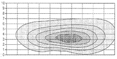
- 7 and 8 are graphs showing the polar coordinate light distribution simulation and the luminance distribution of the road surface in the state where electric power is differentially supplied to each lighting unit.
- 9 and 10 are graphs showing the polar coordinate light distribution simulation and the luminance distribution of the road surface in a state where the same amount of power is supplied to the first to fifth lights and the amount of power is differentially supplied to the sixth light.
- FIG. 1 is a partial configuration diagram of a street lamp to which the dimming control method of the street lamp for reducing power consumption according to the preferred embodiment of the present invention
- Figure 2 is a street lamp for power consumption reduction according to a preferred embodiment of the present invention It is a light distribution schematic diagram for demonstrating the dimming control method.
- the present invention provides the divided first to sixth lighting units 1 to 6 so as to control dimming differently based on a moving direction of the vehicle 10 based on one street light.
- the branches can be applied to street lamps.
- the quantity of the lighting unit or the structure of the street lamp is not related to the specific configuration of the present invention, which will be described later. Do.
- Street lamps installed at the edge of the road is always the traveling direction of the vehicle 10 in the installation position, so the first to sixth lighting unit (1 to 6) is sequentially along the traveling direction of the vehicle 10 Will be illuminated.
- the first lighting unit 1 is the closest to the vehicle's entry direction, and the vehicle 10 driving the road 30 adjacent to the street lamp 20 is illuminated by the first lighting unit 1 as time progresses. From the area A1 to the area A2 illuminated by the second lighting unit 2, the area A3 illuminated by the third light unit 3, the area A4 illuminated by the fourth light unit 4, and the fifth After passing through the area A5 that the lighting unit 5 illuminates, it finally passes through the area that the sixth lighting unit A6 illuminates.
- each of the first to sixth lighting units 1 to 6 has a power amount that determines the degree of dimming. Typically, all of the first to sixth lighting units 1 to 6 are supplied with the same amount of power. It will illuminate the (30) plane.
- a predetermined time zone for example, a night time zone with a large amount of traffic, may be set such that a power amount of 120 watts may be supplied to each of the first to sixth lighting units 1 to 6, for example.
- the first to sixth lighting units 1 to 6 may be set to supply an amount of power of 75.5w.
- the light emitted from the first lighting unit 1 has a light distribution reflected by the road 30 and reflected to the front side of the vehicle 10 before the vehicle 10 arrives at the position of the street light 20. Even in the case of illuminance, the driver recognizes that the luminance is higher. On the contrary, the light emitted from the sixth lighting unit 6 has a light distribution toward the rear portion of the vehicle 10 when the vehicle 10 passes the street light 20, and the driver recognizes that the luminance of the corresponding position is lower. Done.
- the difference in luminance sensed by the driver according to the difference in light distribution becomes an important concept in the configuration of the present invention.
- the road 30 satisfying the regulations by using a minimum amount of power. Luminance can be provided.
- Table 1 below is a state in which the amount of power supplied to each of the first to sixth lighting units 1 to 6 is 120 watts, which may be an illumination state in a night time zone with a lot of traffic.
- the amount of power supplied to all of the first to sixth lighting units 1 to 6, that is, the total amount of power supplied to the street light 20 is 720 watts, and the average brightness is 1.53 cd / m 2 .
- the average luminance means an average of luminance felt by a driver who operates three lanes on the road 30 in which the street lamp 20 is installed. Specifically, the numerical value simulates the luminance felt by the driver 60m before the vehicle 10 reaches the street light 20.
- each of the first to sixth lighting units 1 to 6 includes five LED lights, and the amount of power supplied to each of the LED lights may be 24 watts.
- the average brightness may vary depending on the number of lanes, but under the same conditions, dimming control of all the LEDs belonging to the street lamp to the same extent as in the prior art and the first to sixth lighting units 1 to 6 according to the present invention
- the average luminance in the following description is the luminance of the driver perceived by the driver of the vehicle 10 traveling in three lanes. We assume average.
- the average luminance in Table 1 can be seen to exceed the reference brightness of 1.50d / m 2 when the high volume of the traffic in 1.53cd / m 2.
- the night time zone with heavy traffic may be about 18:00 to 22:00 based on when there is a need to turn on the street light.
- the division of time according to the traffic volume takes into consideration the location of the road or the surrounding conditions, and the factors of the season should also be considered. The above time example should be understood as a division for explaining the present invention to the last.
- the luminance of the road according to the amount of power supplied to the lighting units 1 to 6 is a simulation result using a computer program, and the simulation results at this time are illustrated in FIGS. 3 and 4, respectively.
- 3 and 4 are graphs showing the polar coordinate light distribution simulation and the luminance distribution of the road surface in a state where 24 watts of electric power is supplied to all the lighting units 1 to 6, respectively.
- dimming control for reducing the amount of power supplied to the lighting units 1 to 6 is performed at night time when the driving of the vehicle is reduced.
- a time zone may be set from 22 o'clock to 05 o'clock and the like, and the law of this case should be at least 1 cd / m 2 or more.
- Table 2 below shows a state in which all the lighting units 1 to 6 are dimmed and controlled in the same manner as in the prior art so that the luminance is the minimum value satisfying the law.
- a power amount of 75.5 watts is supplied to each of the lighting units 1 to 6, and the luminance average at this time is 1.04 cd / m 2 , which represents the minimum luminance conforming to the regulations.
- the total amount of power is 453 watts, and it can be seen that the amount of power is significantly reduced compared to the total amount of power (720 watts) required in a time when the operation of the vehicle 10 is large.
- the result of Table 2 is 37.1% dimmed compared to the result of Table 1 described above.
- the result of Table 1 is 100% output (0% dimming) of the street light 20
- the result of Table 2 is 62.9% of the output.
- the vehicle satisfies the luminance standard of the late night time with less traffic. That means 37.1% less energy consumption.
- 5 and 6 are graphs showing the polar coordinate light distribution simulation and the luminance distribution of the road surface in the state where power of 75.5 watts is supplied to the first to sixth lighting units 1 to 6, respectively, as shown in Table 2.
- the dimming method as shown in Table 2 is the same as dimming the entire street light as described above, and the present invention uses the difference in luminance felt by the driver according to the position and light distribution of the lighting units 1 to 6 described above. Compared with the results, we propose the following method to reduce the total power.
- Table 3 below supplies different amounts of power to the first to sixth lighting units 1 to 6 while setting the luminance average to be larger than the legal limit of 1 cd / m 2 .
- Table 3 shows the results of simulating the minimum average luminance value satisfying the legal standard by supplying different amounts of power for each of the first to sixth lighting units 1 to 6.
- the brightness of the area A1 illuminated by the first lighting unit 1 is reflected toward the front of the driver, the brightness of the area A1 is felt to be brighter than that of the other areas under the same conditions.
- the amount of power supplied to (1) is set to be the highest, and the amount of power sequentially reduced from the second lighting unit 2 to the last sixth lighting unit 6 is configured.
- the average brightness can be increased even though the amount of power is lowered.
- the additional power of 4.6% is compared with the example described with reference to Table 2 above. You can save.
- 7 and 8 are graphs showing the polar coordinate light distribution simulation and the luminance distribution of the road surface in the state where electric power is differentially supplied to the respective lighting units 1 to 6 as shown in Table 3.
- the present invention divides the LED street light 20 into a plurality of lighting units (1-6) capable of dimming control along the traveling direction of the vehicle (10), and the lighting unit (sequentially from the direction in which the vehicle 10 faces the street light) ( By reducing the amount of power supplied to 1 ⁇ 6) it is possible to further reduce the power consumption compared to the case of dimming all the LEDs of the LED streetlight uniformly.
- Table 4 below is for explaining another embodiment of the present invention, the same amount of power of the first to fifth lighting units (1 to 5), the differential power of the amount of power supplied to the sixth lighting unit (6).
- the first lighting unit 1 to the fifth lighting unit 5 all supply the same amount of 120 watts
- the sixth lighting unit 6 is 60 watts, which is half the amount of power supplied to the other lighting units. It is a power supply.
- the average luminance exceeds 1 cd / m 2 , which is a provision of related laws and regulations, and it is not necessary to supply different amounts of power to each of the first to sixth lighting units 1 to 6 as in the previous embodiment, and at least the first lighting unit (The total amount of power can be reduced by dimming control so that the amount of power supplied to 1) is greater than the amount of power supplied to the sixth lighting unit 6.
- FIG. 9 and 10 are graphs showing the polar coordinate light distribution simulation and the luminance distribution of the road surface in a state in which power is supplied to the first to sixth lighting units 1 to 6 as shown in Table 4.
- FIG. 9 and 10 are graphs showing the polar coordinate light distribution simulation and the luminance distribution of the road surface in a state in which power is supplied to the first to sixth lighting units 1 to 6 as shown in Table 4.
- the street lamp 20 is not illustrated in FIGS. 1 and 2 in addition to a plurality of lighting units (eg, first to sixth lighting units 1 to 6) capable of dimming control.
- the apparatus may further include a switching mode power supply (SMPS) and a controller, and the controller may perform dimming control by controlling an output of the power supply.
- SMPS switching mode power supply
- the controller may perform dimming control by controlling an output of the power supply.
- the power supply unit may receive power from a power source (not shown), change the current and / or voltage characteristics according to a preset reference, and divide the power according to the control of the controller to divide the first to sixth lighting units ( 1-6) can be delivered.
- the controller controls the power supply unit, and controls the power supply unit to divide the power and transmit the power to the first to sixth lighting units 1 to 6 according to a preset reference.
- the first to sixth lighting units 1 to 6 are controlled.
- the controller may control the power supply unit to perform an operation of transferring the power amount smaller than at least one of the plurality of lighting units in comparison with other lighting units. Also, for example, the controller may control the power supply unit to perform an operation of transferring the power supply so that the amount of power supplied is smaller as the plurality of lighting units are directed from one side to the other side.
- the street light further includes a power supply unit and a controller.
- the power supply unit is controlled to control the amount of power delivered to the lighting units.
- the amount of power delivered to the above-described lighting units may be set in advance (for example, to be controlled by time zone) at the time of initial manufacture.
- the amount of power delivered to the above-described lighting units may be controlled through a remote control.
Landscapes
- Circuit Arrangement For Electric Light Sources In General (AREA)
Abstract
본 발명은 소비전력 절감을 위한 가로등의 디밍 제어방법에 관한 것으로, 가로등의 디밍을 제어하는 방법으로서, 상기 가로등은 각각 디밍제어가 가능한 다수의 조명부를 포함하고, 상기 다수의 조명부 중 적어도 하나 이상의 조명부는 다른 조명부에 비해 그 전력량이 작은 것을 특징으로 한다. 본 발명은 가로등에 마련된 다수의 엘이디를 차량의 진행방향에 따라 임의로 분할하고, 분할된 엘이디들을 각각 다른 정도로 디밍 제어하여 운전자가 느끼는 도로의 휘도 저하를 최소화할 수 있어 에너지를 절감하면서도 운전자가 느끼는 불편을 해소할 수 있는 효과가 있다.
Description
본 발명은 소비전력 절감을 위한 가로등의 디밍 제어방법에 관한 것으로, 교통량을 고려한 시간에 따라 디밍 제어를 수행하되 소비전력을 더욱 절감할 수 있는 소비전력 절감을 위한 가로등의 디밍 제어방법에 관한 것이다.
최근 전력의 소비량이 증가하면서 우리 나라에도 블랙 아웃의 발생 우려가 높아지고, 전력 소모가 많은 시간에 전력 소비를 줄일 수 있는 다양한 정책들이 제안되고 있다. 예를 들어 건물마다 에너지 소비 총량제를 시행하여 기준치를 넘어선 경우에 과징금을 추징하거나, 서울시의 점심시간 변경, 근무복 규정 변경, 지하철의 운행 간격 조정 등 다양한 방법이 시행되고 있다.
현재 도로에 설치된 가로등은 에너지 사용을 줄이기 위하여 주변의 조도에 따라 자동으로 점등 또는 소등되는 방식으로 운영되며, 소비전력이 상대적으로 낮은 엘이디를 광원으로 사용하는 가로등이 제안되고 있다.
그러나 엘이디 가로등을 전면 설치한다고 해도, 야간에는 상시 동일한 조도로 조명을 하게 되면, 차량의 운행이 적은 심야시간에는 불필요한 에너지를 낭비할 수 있는 문제점이 있었다.
이러한 문제점을 고려하여 공개특허 10-2012-0130424호(2012년 12월 3일 공개, 절전 시스템이 구비된 엘이디 가로등 및 그 절전 시스템)에는 차량의 통행 빈도와 관련하여 시간을 구분하고, 차량의 통행 빈도가 낮은 절전시간에는 가로등의 조도를 30% 낮추는 디밍제어를 수행하여 절전을 수행하는 기술에 대하여 기재되어 있다.
그러나 이는 하나의 엘이디 가로등에 포함되는 모든 엘이디들을 동시에 동일한 조도로 디밍 제어하는 것이며, 어느 정도의 절전 효과를 거둘 수 있으나 조도를 일괄적으로 낮춰 차량의 운전자가 인지하는 도로의 휘도는 더욱 낮아지게 되는 문제점이 있었다.
이는 차량의 통행 빈도가 낮은 심야시간에 운행하는 차량의 운전자는 주변의 조도가 낮은 상태에서 쉽게 졸게 되거나, 고속 주행시 주변의 사물에 대한 인지가 낮아져 사고 발생의 위험을 높일 수 있는 문제점이 있었다.
상기와 같은 문제점을 감안한 본 발명이 해결하고자 하는 기술적 과제는, 시간에 따라 조도를 낮추는 디밍 제어를 수행하되, 운전자가 느끼는 도로의 휘도 저하를 최소화할 수 있는 소비전력 절감을 위한 가로등의 디밍 제어방법을 제공함에 있다.
아울러 본 발명이 해결하고자 하는 다른 기술적 과제는, 운전자가 느끼는 휘도가 종래의 디밍 방법과 동일한 조건에서 소비전력를 절감할 수 있는 소비전력 절감을 위한 가로등의 디밍 제어방법을 제공함에 있다.
상기와 같은 과제를 해결하기 위한 본 발명 소비전력 절감을 위한 가로등의 디밍 제어방법은, 가로등의 디밍을 제어하는 방법으로서, 상기 가로등은 각각 디밍제어가 가능한 다수의 조명부를 포함하고, 상기 다수의 조명부 중 적어도 하나 이상의 조명부는 다른 조명부에 비해 그 전력량이 작은 것을 특징으로 한다.
본 발명 소비전력 절감을 위한 가로등의 디밍 제어방법은, 가로등에 마련된 다수의 엘이디를 차량의 진행방향에 따라 임의로 분할하고, 분할된 엘이디들을 각각 다른 정도로 디밍 제어하여 운전자가 느끼는 도로의 휘도 저하를 최소화할 수 있어 에너지를 절감하면서도 운전자가 느끼는 불편을 해소할 수 있는 효과가 있다.
아울러 본 발명은 차량의 진입측 엘이디들의 조도를 차량의 진출측 엘이디들의 조도에 비하여 높게 되도록 배광을 제어하여, 동일한 휘도 조건을 운전자에게 제공하면서도, 전력의 소모를 더욱 줄일 수 있는 효과가 있다.
도 1은 본 발명의 바람직한 실시예에 따른 소비전력 절감을 위한 가로등의 디밍 제어방법이 적용될 수 있는 가로등의 일부 구성도이다.
도 2는 본 발명의 바람직한 실시예에 따른 소비전력 절감을 위한 가로등의 디밍 제어방법을 설명하기 위한 배광 모식도이다.
도 3과 도 4는 각각 모든 조명부에 24watt의 전력량을 공급한 상태에서 극좌표 배광 시뮬레이션과 도로면의 휘도분포를 나타낸 그래프이다.
도 5와 도 6은 각각 제1 내지 제6조명부에 75.5watt의 전력량을 공급한 상태에서 극좌표 배광 시뮬레이션과 도로면의 휘도분포를 나타낸 그래프이다.
도 7과 도 8은 각 조명부에 전력량을 차등 공급한 상태에서 극좌표 배광 시뮬레이션과 도로면의 휘도분포를 나타낸 그래프이다.
도 9와 도 10은 제1 내지 제5조명부에 동일한 전력량을 공급하고, 제6조명부에 전력량을 차등 공급한 상태에서 극좌표 배광 시뮬레이션과 도로면의 휘도분포를 나타낸 그래프이다.
이하, 본 발명 소비전력 절감을 위한 가로등의 디밍 제어방법에 대하여 첨부한 도면을 참조하여 상세히 설명한다.
도 1은 본 발명의 바람직한 실시예에 따른 소비전력 절감을 위한 가로등의 디밍 제어방법이 적용될 수 있는 가로등의 일부 구성도이고, 도 2는 본 발명의 바람직한 실시예에 따른 소비전력 절감을 위한 가로등의 디밍 제어방법을 설명하기 위한 배광 모식도이다.
도 1과 도 2를 각각 참조하면 본 발명은 하나의 가로등을 기준으로 차량(10)의 진행방향을 기준으로 디밍을 서로 다르게 제어할 수 있도록 분할된 제1 내지 제6조명부(1~6)를 가지는 가로등에 적용될 수 있다.
이때 조명부의 수량이나 가로등의 구조는, 이후에 설명될 본 발명의 구체적인 구성은 무관하며, 본 발명을 참조하여 당업자 수준에서 각각 디밍 제어가 가능한 조명부의 수량이나 가로등의 구체적인 구성은 변경실시 함이 가능하다.
도로의 가장자리에 설치되는 가로등은 그 설치위치에서 차량(10)의 진행방향은 항상 일정하며, 따라서 상기 제1 내지 제6조명부(1~6)는 차량(10)의 진행방향을 따라 순차적으로 도로를 조명하게 된다.
즉, 제1조명부(1)는 차량의 진입방향에서 가장 가까운 것이며, 가로등(20)이 인접하는 도로(30)를 주행하는 차량(10)은 시간의 진행에 따라 제1조명부(1)가 조명하는 영역(A1)부터 제2조명부(2)가 조명하는 영역(A2), 제3조명부(3)가 조명하는 영역(A3), 제4조명부(4)가 조명하는 영역(A4), 제5조명부(5)가 조명하는 영역(A5)을 지나 마지막으로 제6조명부(A6)가 조명하는 영역을 순차적으로 거처 지나게 된다.
이때 제1 내지 제6조명부(1~6) 각각은 그 디밍 정도를 결정하는 전력량(Wattage)이 결정되어 있으며, 통상적으로 제1 내지 제6조명부(1~6) 모두가 동일한 전력량을 공급받아 도로(30) 면을 조명하게 된다. 본 발명의 실시예에 따르면, 기 설정된 특정 시간대, 예를 들어, 교통량이 많은 야간 시간대에는 제1 내지 제6조명부(1~6) 각각에 예를 들어, 120w의 전력량이 공급될 수 있도록 설정될 수 있으며, 예를 들어, 교통량이 적은 심야 시간대에는 제1 내지 제6조명부(1~6) 각각에 75.5w의 전력량이 공급될 수 있도록 설정되어 있을 수 있다.
상기 제1 내지 제6조명부(1~6)들 중 가장 가장자리에 위치하는 제1조명부(1)와 제6조명부(6)는 가로등(20)의 중심을 기준으로 가장 먼 영역을 조명하게 된다. 이때 가로등(20)에 의해 조명되는 도로의 면은 소정의 조도 평균값으로 조명되는 것이지만, 차량(10)의 운전자 입장에서 느끼는 도로(30)의 휘도는 제1 내지 제6조명부(1~6)의 배광에 따라 상대적으로 차이가 발생한다.
즉, 제1조명부(1)에서 발산된 광은 도로(30)에서 반사되어 차량(10)이 가로등(20)의 위치에 도착하기 전에 차량(10)의 전면측으로 반사되는 배광을 가지는 것으로, 동일한 조도인 경우라도 운전자 입장에서는 휘도가 더 높은 것으로 인식하게 된다. 반대로 제6조명부(6)에서 발산된 광은 차량(10)이 가로등(20)을 지난 상태에서 차량(10)의 후면부를 향하는 배광을 가지는 것으로, 운전자 입장에서는 해당 위치의 휘도가 더 낮은 것으로 인식하게 된다.
이와 같은 배광의 차이에 따른 운전자가 감지하는 휘도의 차이는 본 발명의 구성에 있어서 중요한 개념이 되며, 이러한 휘도 인지 특성의 차이를 이용하여 최소한의 전력량을 사용하여 법규에 만족하는 도로(30)의 휘도를 제공할 수 있다.
아래의 표 1은 상기 제1 내지 제6조명부(1~6) 각각에 공급되는 전력량이 120watt가 되도록 한 상태이며, 이는 교통량이 많은 야간시간대의 조명상태일 수 있다. 상기 제1 내지 제6조명부(1~6) 모두에 공급된 전력량, 즉 가로등(20)에 공급된 총전력량은 720watt이며, 이때 평균 휘도는 1.53cd/m2이 된다. 상기 평균 휘도라 함은 가로등(20)이 설치된 도로(30)가 3개의 차선이며 각 차선을 운행하는 운전자가 느끼는 휘도의 평균을 뜻하는 것으로 한다. 상기 수치는 구체적으로 차량(10)이 가로등(20)에 도달하기 60m 전에 운전자가 느끼는 휘도를 시뮬레이션 한 것이다.
상기 도 1을 참조할 때 제1 내지 제6조명부(1~6)는 각각 5개의 엘이디조명을 포함하고 있으며, 상기 엘이디조명 각각에 공급되는 전력량은 24watt로 하는 것으로 이해될 수 있다.
상기 평균 휘도는 차선의 수에 따라 차이가 날 수 있으나, 동일한 조건 하에서 종래와 같이 가로등에 속한 모든 엘이디를 동일한 정도로 디밍제어하는 것과 본 발명과 같이 가로등을 제1 내지 제6조명부(1~6)로 나누어 제1 내지 제6조명부(1~6)를 차등 제어하는 방법의 결과 차이를 확인하기 위하여, 이하의 설명에서 평균 휘도는 세 개 차선을 주행하는 차량(10)의 운전자가 인지하는 휘도의 평균인 것으로 한다.
표 1
| 조명부1 | 조명부2 | 조명부3 | 조명부4 | 조명부5 | 조명부6 | 총전력량 | 평균휘도 |
| 120watt | 120watt | 120watt | 120watt | 120watt | 120watt | 720watt | 1.53cd/m2 |
상기 표 1에서 평균휘도는 1.53cd/m2로, 상기 교통량이 많을 때의 기준 휘도인 1.50d/m2을 초과하는 것으로 볼 수 있다. 이때 교통량이 많은 야간 시간대는 가로등의 점등 필요성이 있는 때를 기준으로 18시에서 22시 정도가 될 수 있다. 이와 같은 교통량에 따른 시간의 구분은 도로의 위치나 주변 여건을 고려하고, 계절의 요인도 고려되어야 하는 것으로, 위의 시간의 예는 어디까지나 본 발명을 설명하기 위한 구분으로 이해되어야 한다.
상기 조명부(1~6)들에 공급된 전력량에 따른 도로의 휘도는 컴퓨터 프로그램을 이용한 시뮬레이션 결과이며, 이때의 시뮬레이션 결과를 도 3과 도 4에 각각 도시하였다.
도 3과 도 4는 각각 모든 조명부(1~6)에 24watt의 전력량을 공급한 상태에서 극좌표 배광 시뮬레이션과 도로면의 휘도분포를 나타낸 그래프이다.
이와 같은 상태에서 차량의 운행이 감소하는 심야시간에는 상기 조명부(1~6)에 공급되는 전력량을 줄이는 디밍 제어를 수행한다. 이러한 시간대는 22시부터 05시 등으로 설정될 수 있으며, 이때의 법규는 평균휘도가 적어도 1cd/m2이상이 되어야 한다.
아래의 표 2는 종래와 같은 방식으로 모든 조명부(1~6)를 동일한 정도로 디밍 제어하여 휘도를 법규에 충족하는 최소값이 되도록 제어한 상태를 나타낸다.
표 2
| 조명부1 | 조명부2 | 조명부3 | 조명부4 | 조명부5 | 조명부6 | 총전력량 | 평균휘도 |
| 75.5watt | 75.5watt | 75.5watt | 75.5watt | 75.5watt | 75.5watt | 453watt | 1.04cd/m2 |
상기 표 2에서는 모든 조명부(1~6) 각각에 75.5watt의 전력량을 공급한 상태이며, 이때의 휘도 평균은 1.04cd/m2로 법규에 부합하는 최소한의 휘도를 나타낸다. 이때 총전력량은 453watt로서, 상기 차량(10)의 운행이 많은 시간대에 요구되는 총전력량(720watt)에 비하여 현저하게 전력량이 감소된 것을 알 수 있다.
표 2의 결과는 앞서 설명한 표 1의 결과에 비하여 37.1% 디밍 된 것으로, 표 1의 결과를 가로등(20)의 100% 출력(0% 디밍)이라고 할 때, 표 2의 결과는 62.9%의 출력 상태로 차량의 통행이 적은 심야시간의 휘도 기준을 만족하는 결과를 나타낼 수 있다. 즉, 에너지의 소비를 37.1% 절감할 수 있음을 뜻한다.
도 5와 도 6은 각각 표 2와 같이 제1 내지 제6조명부(1~6)에 75.5watt의 전력량을 공급한 상태에서 극좌표 배광 시뮬레이션과 도로면의 휘도분포를 나타낸 그래프이다.
그러나 표 2와 같이 디밍하는 방법은 앞서 설명한 바와 같이 가로등 전체를 디밍하는 것과 동일하며, 본 발명은 앞서 설명한 조명부(1~6)의 위치와 배광에 따라 운전자가 느끼는 휘도의 차이를 이용하여 표 2의 결과에 비하여 총전력량을 더 줄일 수 있는 방법을 다음과 같이 제안한다.
아래의 표 3은 휘도 평균을 법규상 제한인 1cd/m2보다 큰 값이 되도록 하면서, 제1 내지 제6조명부(1~6)에 각기 다른 전력량을 공급한다.
표 3
| 조명부1 | 조명부2 | 조명부3 | 조명부4 | 조명부5 | 조명부6 | 총전력량 | 평균휘도 |
| 110watt | 90watt | 84watt | 72watt | 60watt | 48watt | 420watt | 1.06cd/m2 |
상기 표 3에서는 제1 내지 제6조명부(1~6) 마다 서로 다른 전력량을 공급하여 법규 기준을 만족하는 최소한의 평균휘도 값을 시뮬레이션 한 결과이다.
이때 앞서 설명한 바와 같이 제1조명부(1)가 조명하는 영역(A1)의 휘도는 운전자의 정면을 향하여 광이 반사되기 때문에 동일 조건에서 다른 영역들의 휘도에 비해 더 밝게 느껴지게 되는 것으로, 제1조명부(1)에 공급되는 전력량을 가장 높게 설정하고, 제2조명부(2)부터 마지막 제6조명부(6)까지 순차적으로 감소하는 전력량을 공급하도록 구성된다.
구체적으로 제1조명부(1)에는 110watt, 제2조명부(2)에는 90watt, 제3조명부(3)에는 84watt, 제4조명부(4)에는 72watt, 제5조명부(5)에는 60watt, 제조명부(6)에는 48watt의 전력량을 공급한다. 이와 같은 구체적인 수치는 가변될 수 있으며, 중요한 점은 제1조명부(1)에 공급되는 전력량에 비해 제6조명부(6)에 공급되는 전력량은 반드시 더 적은 것으로 하고, 제1조명부(1)로부터 제6조명부(6)까지의 공급전력량이 순차적으로 감소하도록 하는 것이 바람직하다.
상기 표 3의 예와 같이 총전력량이 420watt가 되도록 제1 내지 제6조명부(1~6)들 각각에 공급되는 전력량을 조절하여도 평균휘도가 법규기준치를 만족하도록 할 수 있으며, 이때 디밍은 상기 표 1의 결과에 대하여 41.7%가 되며, 출력량은 58.3%가 된다.
이는 앞서 모든 조명부(1~6)에 동일한 전력량을 공급한 경우에 비하여 더 적은 전력량을 공급하고도 평균휘도는 더 높일 수 있는 것으로, 상기 표 2를 참고하여 설명한 예에 비하여 4.6%의 추가적인 전력량을 절감할 수 있게 된다.
도 7과 도 8은 표 3과 같이 각 조명부(1~6)에 전력량을 차등 공급한 상태에서 극좌표 배광 시뮬레이션과 도로면의 휘도분포를 나타낸 그래프이다.
이처럼 본 발명은 엘이디 가로등(20)을 차량(10)의 진행방향을 따라 디밍의 제어가 가능한 다수의 조명부(1~6)로 분할하고, 차량(10)이 가로등을 향하는 방향에서부터 순차적으로 조명부(1~6)에 공급되는 전력량을 감소시켜 공급하여 엘이디 가로등의 모든 엘이디를 균일하게 디밍하는 경우에 비하여 소비전력을 더 절감할 수 있게 된다.
아래의 표 4는 본 발명의 다른 실시예를 설명하기 위한 것으로, 제1 내지 제5조명부(1~5)의 전력량을 동일하게 하고, 제6조명부(6)에 공급되는 전력량을 차등적용한 것이다.
표 4
| 조명부1 | 조명부2 | 조명부3 | 조명부4 | 조명부5 | 조명부6 | 총전력량 | 평균휘도 |
| 120watt | 120watt | 120watt | 120watt | 120watt | 60watt | 660watt | 1.45cd/m2 |
상기 표 4에 기재한 바와 같이 제1조명부(1)부터 제5조명부(5)까지는 모두 동일한 120watt의 전력량을 공급하고, 제6조명부(6)는 다른 조명부들에 공급되는 전력량의 절반인 60watt의 전력량을 공급한 것이다.
이때 평균휘도는 관련 법규의 규정인 1cd/m2을 초과하는 것이며, 앞선 실시예와 같이 제1 내지 제6조명부(1~6) 모두에 각각 다른 전력량을 공급할 필요는 없으며, 적어도 제1조명부(1)에 공급되는 전력량이 제6조명부(6)에 공급되는 전력량보다 크게 되도록 디밍 제어하여 총전력량을 줄일 수 있다.
도 9와 도 10은 표 4와 같이 제1 내지 제6조명부(1~6)에 전력량을 공급한 상태에서 극좌표 배광 시뮬레이션과 도로면의 휘도분포를 나타낸 그래프이다.
한편, 본 발명의 일 실시예에 따르면 가로등(20)은 디밍 제어가 가능한 다수의 조명부(예: 제1 내지 제6조명부(1~6))외에도, 도 1 및 도 2에 도시하지 않았지만 예를 들어, 전원공급부(SMPS; Switching Mode Power Supply)와 컨트롤러를 더 포함할 수 있으며, 컨트롤러가 전원 공급부의 출력을 제어하여 디밍 제어를 수행할 수 있다.
상기 전원공급부는 전력원(미도시)으로부터 전력을 공급 받아, 기 설정된 기준에 따라, 전류 및/또는 전압 특성을 변화할 수 있으며, 컨트롤러의 제어에 따라 전력을 분할하여 제1 내지 제6조명부(1~6)로 전달할 수 있다.
상기 컨트롤러는 전원공급부를 제어하여, 전원공급부가 기 설정된 기준에 따라, 전력을 분할하여 제1 내지 제6조명부(1~6)로 전달하도록 제어하여, 제1 내지 제6조명부(1~6)의 디밍을 제어하도록 할 수 있다.
예를 들어, 상기 컨트롤러는 전원 공급부가 다수의 조명부 중 적어도 하나 이상의 조명부에서 다른 조명부에 비해 그 전력량이 작게 전달하는 동작을 수행하도록 제어할 수 있다. 또한, 예를 들어, 상기 컨트롤러는 전원 공급부가, 상기 다수의 조명부가 일측에서 타측으로 향할수록 공급되는 전력량이 더 작아지도록 전달하는 동작을 수행하도록 제어할 수 있다.
본 발명은 상기 실시예에 한정되지 않고 본 발명의 기술적 요지를 벗어나지 아니하는 범위 내에서 다양하게 수정, 변형되어 실시될 수 있음은 본 발명이 속하는 기술분야에서 통상의 지식을 가진 자에 있어서 자명한 것이다.
예를 들어, 상기 실시예에서는 가로등이 전원공급부와 컨트롤러를 더 포함하여, 컨트롤러의 제어에 따라, 전원공급부가 제어되어, 조명부들에 전달되는 전력의 전력량이 제어되는 것으로 설명하였지만, 본 발명의 다른 실시예에 따르면, 상술한 조명부들에 전달되는 전력의 전력량은 최초 제조 시, 미리 설정(예를 들어, 시간대 별로 구분되게 제어되도록)해둘 수 있다. 또한, 본 발명의 또다른 실시예에 따르면, 상술한 조명부들에 전달되는 전력의 전력량은 원격 제어를 통해 제어될 수 있다.
Claims (6)
- 가로등의 디밍을 제어하는 방법으로서,상기 가로등은 각각 디밍제어가 가능한 다수의 조명부를 포함하고,상기 다수의 조명부 중 적어도 하나 이상의 조명부는 다른 조명부에 비해 그 전력량이 작은 것을 특징으로 하는 소비전력 절감을 위한 가로등의 디밍 제어방법.
- 제1항에 있어서,상기 다수의 조명부는 일측에서 타측으로 향할수록 공급되는 전력량이 더 적어지도록 각각 디밍 제어하는 것을 특징으로 하는 소비전력 절감을 위한 가로등의 디밍 제어방법.
- 제2항에 있어서,상기 가로등이 차량 주행도로에 설치된 경우,상기 일측에서 타측 방향은 차량의 주행방향과 동일한 것을 특징으로 하는 소비전력 절감을 위한 가로등의 디밍 제어방법.
- 가로등에 있어서,디밍 제어가 가능한 다수의 조명부와,전력을 공급받으며, 컨트롤러의 제어에 따라 상기 전력을 분할하여 상기 다수의 조명부에 전달하는 전원 공급부와,상기 전원 공급부가 기 설정된 기준에 따라, 상기 전력을 분할하여 상기 다수의 조명부에 전달하는 동작을 수행하도록 제어하는 컨트롤러 포함하는 가로등.
- 제 4항에 있어서, 상기 컨트롤러는,상기 전원 공급부가, 상기 다수의 조명부 중 적어도 하나 이상의 조명부에는 다른 조명부에 비해 그 전력량이 작게 전달하는 동작을 수행하도록 제어하는 것을 특징으로 하는 가로등.
- 제5항에 있어서, 상기 컨트롤러는,상기 전원 공급부가, 상기 다수의 조명부가 일측에서 타측으로 향할수록 공급되는 전력량이 더 작아지도록 전달하는 동작을 수행하도록 제어하는 것을 특징으로 하는 가로등.
Priority Applications (3)
| Application Number | Priority Date | Filing Date | Title |
|---|---|---|---|
| JP2016521224A JP6140894B2 (ja) | 2013-06-25 | 2014-06-25 | 消費電力節減のための街灯の調光制御方法及びその街灯 |
| EP14818046.6A EP3016481A4 (en) | 2013-06-25 | 2014-06-25 | Method for controlling dimming of street lamp to reduce power consumption and street lamp |
| US14/981,170 US20160113089A1 (en) | 2013-06-25 | 2015-12-28 | Method for controlling dimming of street lamp to reduce power consumption and street lamp |
Applications Claiming Priority (2)
| Application Number | Priority Date | Filing Date | Title |
|---|---|---|---|
| KR20130072768A KR20150000570A (ko) | 2013-06-25 | 2013-06-25 | 소비전력 절감을 위한 가로등의 디밍 제어방법 |
| KR10-2013-0072768 | 2013-06-25 |
Related Child Applications (1)
| Application Number | Title | Priority Date | Filing Date |
|---|---|---|---|
| US14/981,170 Continuation US20160113089A1 (en) | 2013-06-25 | 2015-12-28 | Method for controlling dimming of street lamp to reduce power consumption and street lamp |
Publications (1)
| Publication Number | Publication Date |
|---|---|
| WO2014209002A1 true WO2014209002A1 (ko) | 2014-12-31 |
Family
ID=52142261
Family Applications (1)
| Application Number | Title | Priority Date | Filing Date |
|---|---|---|---|
| PCT/KR2014/005614 WO2014209002A1 (ko) | 2013-06-25 | 2014-06-25 | 소비전력 절감을 위한 가로등의 디밍 제어방법 및 그 가로등 |
Country Status (5)
| Country | Link |
|---|---|
| US (1) | US20160113089A1 (ko) |
| EP (1) | EP3016481A4 (ko) |
| JP (1) | JP6140894B2 (ko) |
| KR (1) | KR20150000570A (ko) |
| WO (1) | WO2014209002A1 (ko) |
Families Citing this family (4)
| Publication number | Priority date | Publication date | Assignee | Title |
|---|---|---|---|---|
| KR102270708B1 (ko) | 2017-11-29 | 2021-06-30 | 한국전기연구원 | 가로등 전력제어장치 및 가로등 전력제어방법 |
| CN108419343A (zh) * | 2018-02-25 | 2018-08-17 | 海宁川达科技有限公司 | 太阳能路灯监控系统 |
| CN109348596A (zh) * | 2018-12-03 | 2019-02-15 | 平顶山学院 | 一种基于plc的城市路灯智能控制系统 |
| CN110708841B (zh) * | 2019-08-15 | 2021-11-30 | 安徽文康科技有限公司 | 一种智慧路灯自适应节能控制方法 |
Citations (6)
| Publication number | Priority date | Publication date | Assignee | Title |
|---|---|---|---|---|
| KR20100113304A (ko) * | 2009-04-13 | 2010-10-21 | 벽산엔지니어링주식회사 | 도로조명 시스템 |
| KR20110082651A (ko) * | 2010-01-12 | 2011-07-20 | 주식회사 아이엔오 | 터널등 제어장치 |
| JP2012174663A (ja) * | 2011-02-24 | 2012-09-10 | Optex Co Ltd | 調光照明装置および調光照明システム |
| KR20120110826A (ko) * | 2011-03-30 | 2012-10-10 | 주식회사엘이디파워 | 태블릿 이동 통신기기를 이용한 조명 제어 시스템 및 방법 |
| KR20120130424A (ko) | 2011-05-23 | 2012-12-03 | 김건호 | 절전 시스템이 구비된 엘이디 가로등 및 그 절전 시스템 |
| KR20120140033A (ko) * | 2011-06-20 | 2012-12-28 | 삼성전자주식회사 | 가로등 디밍 제어 장치 및 방법 |
Family Cites Families (12)
| Publication number | Priority date | Publication date | Assignee | Title |
|---|---|---|---|---|
| US7471051B1 (en) * | 2004-09-24 | 2008-12-30 | Avatar Systems Llc | Advanced low voltage lighting system |
| JP4651528B2 (ja) * | 2005-12-16 | 2011-03-16 | 小糸工業株式会社 | 点灯制御装置および照明装置 |
| US8588830B2 (en) * | 2007-02-02 | 2013-11-19 | Inovus Solar, Inc | Wireless autonomous solar-powered outdoor lighting and energy and information management network |
| US8476565B2 (en) * | 2007-06-29 | 2013-07-02 | Orion Energy Systems, Inc. | Outdoor lighting fixtures control systems and methods |
| JP2010067415A (ja) * | 2008-09-09 | 2010-03-25 | Stanley Electric Co Ltd | Led照明灯具 |
| WO2011106868A1 (en) * | 2010-03-01 | 2011-09-09 | Led Roadway Lighting Ltd. | Gps-based streetlight wireless command and control system |
| KR100981274B1 (ko) * | 2010-03-11 | 2010-09-10 | 주식회사 베스트디지탈 | 자동 조명제어 시스템 |
| EP2369899A1 (en) * | 2010-03-25 | 2011-09-28 | Koninklijke Philips Electronics N.V. | Method for controlling an outdoor lighting system, a computer program product, a controlling device and an outdoor lighting system |
| US8502456B2 (en) * | 2010-09-09 | 2013-08-06 | Ipixc Llc | Managing light system energy use |
| WO2012154234A1 (en) * | 2011-01-28 | 2012-11-15 | Sensus Usa Inc. | Method and apparatus for distributed lighting control |
| GB2488337A (en) * | 2011-02-23 | 2012-08-29 | Sharp Kk | A lighting device |
| US20130169165A1 (en) * | 2011-12-15 | 2013-07-04 | Laurence P. Sadwick | Multi-Phase Lighting Driver |
-
2013
- 2013-06-25 KR KR20130072768A patent/KR20150000570A/ko not_active Application Discontinuation
-
2014
- 2014-06-25 JP JP2016521224A patent/JP6140894B2/ja not_active Expired - Fee Related
- 2014-06-25 WO PCT/KR2014/005614 patent/WO2014209002A1/ko active Application Filing
- 2014-06-25 EP EP14818046.6A patent/EP3016481A4/en not_active Withdrawn
-
2015
- 2015-12-28 US US14/981,170 patent/US20160113089A1/en not_active Abandoned
Patent Citations (6)
| Publication number | Priority date | Publication date | Assignee | Title |
|---|---|---|---|---|
| KR20100113304A (ko) * | 2009-04-13 | 2010-10-21 | 벽산엔지니어링주식회사 | 도로조명 시스템 |
| KR20110082651A (ko) * | 2010-01-12 | 2011-07-20 | 주식회사 아이엔오 | 터널등 제어장치 |
| JP2012174663A (ja) * | 2011-02-24 | 2012-09-10 | Optex Co Ltd | 調光照明装置および調光照明システム |
| KR20120110826A (ko) * | 2011-03-30 | 2012-10-10 | 주식회사엘이디파워 | 태블릿 이동 통신기기를 이용한 조명 제어 시스템 및 방법 |
| KR20120130424A (ko) | 2011-05-23 | 2012-12-03 | 김건호 | 절전 시스템이 구비된 엘이디 가로등 및 그 절전 시스템 |
| KR20120140033A (ko) * | 2011-06-20 | 2012-12-28 | 삼성전자주식회사 | 가로등 디밍 제어 장치 및 방법 |
Also Published As
| Publication number | Publication date |
|---|---|
| KR20150000570A (ko) | 2015-01-05 |
| US20160113089A1 (en) | 2016-04-21 |
| EP3016481A1 (en) | 2016-05-04 |
| EP3016481A4 (en) | 2017-03-22 |
| JP6140894B2 (ja) | 2017-06-07 |
| JP2016524805A (ja) | 2016-08-18 |
Similar Documents
| Publication | Publication Date | Title |
|---|---|---|
| WO2014209002A1 (ko) | 소비전력 절감을 위한 가로등의 디밍 제어방법 및 그 가로등 | |
| WO2013051893A2 (ko) | 엘이디 조명장치의 조명방법 | |
| CN103415113A (zh) | 一种led隧道灯系统及led隧道灯的亮度控制方法 | |
| CN204272438U (zh) | 色温和亮度无极调节的机车司机室照明灯 | |
| CN109005613A (zh) | 隧道照明智能控制方法及系统 | |
| CN106658895A (zh) | 一种双旁路大功率调光控制器 | |
| CN203537617U (zh) | 一种智能照明控制管理系统 | |
| CN207758788U (zh) | 一种车厢及列车 | |
| CN106793260A (zh) | 一种操作及控制集成的机内照明系统 | |
| CN106888536B (zh) | 一种电梯的灯光控制系统 | |
| JP2014035932A (ja) | 照明制御システムおよび照明制御方法 | |
| WO2016095494A1 (zh) | 带有色温调节功能的led可控硅智能电源及led灯具 | |
| CN105072786A (zh) | 一种路灯自动控制系统 | |
| CN203574892U (zh) | 一种可变色温可调光led照明系统 | |
| JPH11204272A (ja) | 道路照明装置 | |
| CN108534089A (zh) | 日间行车灯联动控制策略和日间行车灯 | |
| CN216562395U (zh) | 一种主动式隧道诱导装置 | |
| CN204345447U (zh) | 一种像素灯 | |
| CN203467019U (zh) | 一种led隧道灯系统 | |
| CN204922622U (zh) | 具有反光和警示导引功能的隧道灯及隧道照明系统 | |
| CN106439724A (zh) | 车厢照明方法及系统 | |
| CN108844039A (zh) | 一种车灯多功能配光结构及配光方法 | |
| CN204340850U (zh) | 汽车前组合灯 | |
| CN108235539A (zh) | 社区照明信息的管理系统 | |
| CN213662006U (zh) | 一种城市轨道交通车辆段检修库智能照明系统 |
Legal Events
| Date | Code | Title | Description |
|---|---|---|---|
| 121 | Ep: the epo has been informed by wipo that ep was designated in this application |
Ref document number: 14818046 Country of ref document: EP Kind code of ref document: A1 |
|
| ENP | Entry into the national phase |
Ref document number: 2016521224 Country of ref document: JP Kind code of ref document: A |
|
| NENP | Non-entry into the national phase |
Ref country code: DE |
|
| WWE | Wipo information: entry into national phase |
Ref document number: 2014818046 Country of ref document: EP |