WO2014208385A1 - 光源装置及び表示装置 - Google Patents
光源装置及び表示装置 Download PDFInfo
- Publication number
- WO2014208385A1 WO2014208385A1 PCT/JP2014/065899 JP2014065899W WO2014208385A1 WO 2014208385 A1 WO2014208385 A1 WO 2014208385A1 JP 2014065899 W JP2014065899 W JP 2014065899W WO 2014208385 A1 WO2014208385 A1 WO 2014208385A1
- Authority
- WO
- WIPO (PCT)
- Prior art keywords
- light source
- guide plate
- light guide
- light
- source device
- Prior art date
- Legal status (The legal status is an assumption and is not a legal conclusion. Google has not performed a legal analysis and makes no representation as to the accuracy of the status listed.)
- Ceased
Links
Images




Classifications
-
- G—PHYSICS
- G02—OPTICS
- G02B—OPTICAL ELEMENTS, SYSTEMS OR APPARATUS
- G02B6/00—Light guides; Structural details of arrangements comprising light guides and other optical elements, e.g. couplings
- G02B6/0001—Light guides; Structural details of arrangements comprising light guides and other optical elements, e.g. couplings specially adapted for lighting devices or systems
- G02B6/0011—Light guides; Structural details of arrangements comprising light guides and other optical elements, e.g. couplings specially adapted for lighting devices or systems the light guides being planar or of plate-like form
- G02B6/0081—Mechanical or electrical aspects of the light guide and light source in the lighting device peculiar to the adaptation to planar light guides, e.g. concerning packaging
- G02B6/0086—Positioning aspects
- G02B6/0088—Positioning aspects of the light guide or other optical sheets in the package
-
- G—PHYSICS
- G02—OPTICS
- G02B—OPTICAL ELEMENTS, SYSTEMS OR APPARATUS
- G02B6/00—Light guides; Structural details of arrangements comprising light guides and other optical elements, e.g. couplings
- G02B6/0001—Light guides; Structural details of arrangements comprising light guides and other optical elements, e.g. couplings specially adapted for lighting devices or systems
- G02B6/0011—Light guides; Structural details of arrangements comprising light guides and other optical elements, e.g. couplings specially adapted for lighting devices or systems the light guides being planar or of plate-like form
- G02B6/0081—Mechanical or electrical aspects of the light guide and light source in the lighting device peculiar to the adaptation to planar light guides, e.g. concerning packaging
- G02B6/0086—Positioning aspects
- G02B6/0091—Positioning aspects of the light source relative to the light guide
-
- G—PHYSICS
- G02—OPTICS
- G02F—OPTICAL DEVICES OR ARRANGEMENTS FOR THE CONTROL OF LIGHT BY MODIFICATION OF THE OPTICAL PROPERTIES OF THE MEDIA OF THE ELEMENTS INVOLVED THEREIN; NON-LINEAR OPTICS; FREQUENCY-CHANGING OF LIGHT; OPTICAL LOGIC ELEMENTS; OPTICAL ANALOGUE/DIGITAL CONVERTERS
- G02F1/00—Devices or arrangements for the control of the intensity, colour, phase, polarisation or direction of light arriving from an independent light source, e.g. switching, gating or modulating; Non-linear optics
- G02F1/01—Devices or arrangements for the control of the intensity, colour, phase, polarisation or direction of light arriving from an independent light source, e.g. switching, gating or modulating; Non-linear optics for the control of the intensity, phase, polarisation or colour
- G02F1/13—Devices or arrangements for the control of the intensity, colour, phase, polarisation or direction of light arriving from an independent light source, e.g. switching, gating or modulating; Non-linear optics for the control of the intensity, phase, polarisation or colour based on liquid crystals, e.g. single liquid crystal display cells
- G02F1/133—Constructional arrangements; Operation of liquid crystal cells; Circuit arrangements
- G02F1/1333—Constructional arrangements; Manufacturing methods
- G02F1/133308—Support structures for LCD panels, e.g. frames or bezels
-
- G—PHYSICS
- G02—OPTICS
- G02F—OPTICAL DEVICES OR ARRANGEMENTS FOR THE CONTROL OF LIGHT BY MODIFICATION OF THE OPTICAL PROPERTIES OF THE MEDIA OF THE ELEMENTS INVOLVED THEREIN; NON-LINEAR OPTICS; FREQUENCY-CHANGING OF LIGHT; OPTICAL LOGIC ELEMENTS; OPTICAL ANALOGUE/DIGITAL CONVERTERS
- G02F1/00—Devices or arrangements for the control of the intensity, colour, phase, polarisation or direction of light arriving from an independent light source, e.g. switching, gating or modulating; Non-linear optics
- G02F1/01—Devices or arrangements for the control of the intensity, colour, phase, polarisation or direction of light arriving from an independent light source, e.g. switching, gating or modulating; Non-linear optics for the control of the intensity, phase, polarisation or colour
- G02F1/13—Devices or arrangements for the control of the intensity, colour, phase, polarisation or direction of light arriving from an independent light source, e.g. switching, gating or modulating; Non-linear optics for the control of the intensity, phase, polarisation or colour based on liquid crystals, e.g. single liquid crystal display cells
- G02F1/133—Constructional arrangements; Operation of liquid crystal cells; Circuit arrangements
- G02F1/1333—Constructional arrangements; Manufacturing methods
- G02F1/1335—Structural association of cells with optical devices, e.g. polarisers or reflectors
- G02F1/1336—Illuminating devices
- G02F1/133602—Direct backlight
- G02F1/133608—Direct backlight including particular frames or supporting means
-
- G—PHYSICS
- G02—OPTICS
- G02F—OPTICAL DEVICES OR ARRANGEMENTS FOR THE CONTROL OF LIGHT BY MODIFICATION OF THE OPTICAL PROPERTIES OF THE MEDIA OF THE ELEMENTS INVOLVED THEREIN; NON-LINEAR OPTICS; FREQUENCY-CHANGING OF LIGHT; OPTICAL LOGIC ELEMENTS; OPTICAL ANALOGUE/DIGITAL CONVERTERS
- G02F1/00—Devices or arrangements for the control of the intensity, colour, phase, polarisation or direction of light arriving from an independent light source, e.g. switching, gating or modulating; Non-linear optics
- G02F1/01—Devices or arrangements for the control of the intensity, colour, phase, polarisation or direction of light arriving from an independent light source, e.g. switching, gating or modulating; Non-linear optics for the control of the intensity, phase, polarisation or colour
- G02F1/13—Devices or arrangements for the control of the intensity, colour, phase, polarisation or direction of light arriving from an independent light source, e.g. switching, gating or modulating; Non-linear optics for the control of the intensity, phase, polarisation or colour based on liquid crystals, e.g. single liquid crystal display cells
- G02F1/133—Constructional arrangements; Operation of liquid crystal cells; Circuit arrangements
- G02F1/1333—Constructional arrangements; Manufacturing methods
- G02F1/133308—Support structures for LCD panels, e.g. frames or bezels
- G02F1/133314—Back frames
Definitions
- the present invention relates to an edge light type light source device and a display device including the light source device.
- Such a display device includes a display panel that displays a video on the front side and has a rectangular plate shape, and a light source unit that is disposed on the back side of the display panel and irradiates the display panel with light.
- the light source unit includes an edge light system in which a light guide plate and a support that supports the light guide plate are disposed on the back side of the display panel, and a light source such as a light emitting diode (LED) is disposed on an end surface (side surface) side of the light guide plate.
- LED light emitting diode
- the edge light type light source unit light incident from the end surface of the light guide plate is emitted from one surface of the light guide plate while diffusing in the light guide plate, and is incident on the display panel.
- Patent Document 1 In order to emit uniform light in an edge light type light source unit, it is necessary to prevent the positional relationship between the light guide plate and the light source from shifting, and it is important to keep the distance between the light guide plate and the light source constant. is there. Therefore, in Patent Document 1, it is proposed to provide a regulation part that regulates the distance between the LED light source on the LED substrate and the light guide plate on the substrate holding member that holds the LED substrate.
- an elastic member made of, for example, silicon rubber is interposed between a substrate (LED substrate) on which a light source is mounted and a light guide plate, and a constant distance between the light source and the light guide plate is ensured.
- the light source unit is required to be made thinner and smaller, and it is difficult to provide the substrate holding member with a regulating portion as disclosed in Patent Document 1. .
- a display device is often used in a standing state.
- the light guide plate is enlarged due to the increase in size of the display panel.
- the optical plate is displaced downward by its own weight and the interposed elastic member is deformed.
- heat generated when the light source emits light may be conducted to the light guide plate, and the light guide plate may expand due to heat from the light source.
- the light guide plate may contact the light source and damage the light source.
- An object of the present invention is to provide a light source device that can be reduced in size and can appropriately maintain the position of the light guide plate with respect to the light source unit, and a display device including the light source device.
- the light source device includes a rectangular light guide plate, a light source unit disposed opposite to two opposite end surfaces of the light guide plate, and a holding body that holds the light source unit and the light guide plate, and the two end surfaces.
- the light source device that emits light from the light source unit incident on the light guide plate from one surface of the light guide plate, the light source device includes a holding unit that is attached to the holding body and holds the light guide plate between the other two end surfaces. It is characterized by that.
- the position of the light guide plate with respect to the light source portion can be kept stable.
- a light source device that can emit uniform light can be realized.
- the clamping member is provided on the two end face sides where the light source section is not opposed, the configuration on the two end face side where the light source section is opposed is not complicated, and the light source device can be downsized.
- each of the sandwiching portions has an elastic member that is biased in a direction toward each other.
- the light guide plate is held by the elastic member, for example, even when the light guide plate expands due to heat from the light source unit, the light guide plate can be stably held. Therefore, the position of the light guide plate can be kept stable.
- the light guide plate has engaging portions that engage with the holding portions at positions opposite to the other two end surfaces, respectively, and the holding portions are each of the engaging portions. It has the latching
- the position of the light guide plate relative to the light source portion can be kept more stable.
- the engaging portion is a notch that penetrates the light guide plate in a thickness direction
- the holding body includes a support plate that supports the light guide plate on one surface, and the support The plate has a through-hole penetrating at a position corresponding to the notch, and the locking portion is movable along the other surface to a position corresponding to the through-hole on the other surface of the support plate.
- the engaging portion of the holding member that holds the light guide plate is engaged with the notch provided in the light guide plate, the position of the light guide plate relative to the light source portion can be kept more stable.
- the movable plate piece urges the plate piece arranged along the other surface of the support plate, and the plate piece in a direction approaching the movable plate piece of the opposing clamping unit. And an elastic member.
- the movable plate pieces constituting the holding portion (locking portion) are urged in a direction approaching each other by the elastic member, and the light guide plate is held by the elastic member, so that the light guide plate is stably held.
- the position of the light guide plate can be kept stable.
- the light source device is characterized in that the clamping portion is provided at a plurality of locations.
- the position of the light guide plate relative to the light source unit can be more firmly fixed by sandwiching the light guide plate at a plurality of locations.
- a display device includes any one of the light source devices described above and a display panel that displays an image using light emitted from the light source device.
- a light source device that can keep the position of the light guide plate stable, it is possible to display an image using uniform light emitted from the light source device, and display quality is improved.
- the light guide plate is sandwiched between the other two end surfaces, so that the distance between the light guide plate and each light source unit is constant. And uniform light emission is possible.
- the clamping part which clamps a light-guide plate is provided in the other two end surface side, the structure of the two end surface side in which the light source part is opposingly arranged can be simplified, and size reduction of a light source device is attained. Therefore, even when the size of the light source device is limited, the position of the light guide plate can be appropriately maintained.
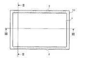
- FIG. 3 is a front view of the display device according to Embodiment 1.
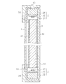
- FIG. It is a longitudinal cross-sectional view by the II-II line in FIG.
- FIG. 3 is a transverse sectional view taken along line III-III in FIG. 1.
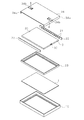
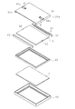
- FIG. 3 is an exploded perspective view illustrating a main configuration of the display device according to the first embodiment. It is explanatory drawing which shows the attachment procedure of a clamping member. It is explanatory drawing which shows the attachment procedure of a clamping member.
- FIG. 3 is a transverse sectional view taken along line III-III in FIG. 1.
- FIG. 10 is an exploded perspective view showing a main part configuration of a display device according to a second embodiment.
- FIG. 10 is an explanatory diagram illustrating a procedure for attaching the clamping member according to the second embodiment.
- FIG. 10 is an explanatory diagram illustrating a procedure for attaching the clamping member according to the second embodiment.
- FIG. 1 is a front view of a display device according to Embodiment 1
- FIG. 2 is a longitudinal sectional view taken along line II-II in FIG. 1
- FIG. 3 is a transverse sectional view taken along line III-III in FIG.
- FIG. 4 is an exploded perspective view showing a main configuration of the display device according to the first embodiment.
- the display device of Embodiment 1 is a liquid crystal display device including an edge light type light source device.
- the display device according to the first embodiment includes a rectangular plate-like liquid crystal panel (display panel) 1 and a light source device that irradiates the liquid crystal panel 1 with light.
- the liquid crystal panel 1 is configured, for example, by arranging a plurality of liquid crystal elements in a two-dimensional matrix. The peripheral edge of the liquid crystal panel 1 is covered with a bezel 10 from the display screen side.
- the light source device includes two light source units 2 and a light guide plate 3. Each light source unit 2 includes a strip-shaped substrate 22, a light source 21 mounted along the longitudinal direction of the substrate 22, and a prismatic holding plate 23 that holds the substrate 22 and the light source 21.
- the light source 21 is, for example, a light emitting diode (LED), and a plurality of light emitting diodes are mounted along the longitudinal direction of the substrate 22.
- the light source 21 is a light-emitting diode, a cold cathode fluorescent lamp (CCFL), an external electrode fluorescent lamp (EEFL), a hot cathode fluorescent lamp (HCFL), or the like. May be.
- the light guide plate 3 is made of a synthetic resin such as highly transparent acrylic resin or polycarbonate resin, and is formed in a rectangular plate shape.
- An optical sheet 31 is attached to one surface of the light guide plate 3, and a reflective sheet 32 is attached to the other surface.
- the reflection sheet 32 is a sheet made of a synthetic resin having high reflectivity, and a surface of the reflection sheet 32 facing the light guide plate 3 may be coated with a highly reflective paint.
- the optical sheet 31 is a sheet in which, for example, a diffusion sheet, a prism sheet, a polarizing sheet, and the like are laminated, and emits incident light as uniform planar light.
- the diffusion sheet is, for example, a PET (polyethylene terephthalate) film or a polycarbonate resin film, and has a function of diffusing incident light.
- the prism sheet is configured, for example, by forming a regular prism pattern with acrylic resin on one side of a polyester sheet material.
- the polarizing sheet is, for example, a polyethylene naphthalate film, and has a function of converting incident light into linearly polarized light.
- the light source unit 2 having the above-described configuration is disposed so as to face the upper end surface and the lower end surface of the light guide plate 3 so that light from the light source 21 enters.
- the back cover (support plate) 34 is a rectangular flat plate that is slightly larger than the light guide plate 3 (hereinafter also referred to as the light guide plate 3) covered with the optical sheet 31 and the reflection sheet 32.
- a protruding plate 34a that rises vertically in the same direction is provided.
- the back cover 34 supports the light guide plate 3 and the light source unit 2 from the reflection sheet 32 side on one side on which the protruding plate 34a is provided.
- the backlight holding part 33 is formed in a rectangular frame shape slightly larger than the light guide plate 3 and covers the periphery of the light guide plate 3 from the optical sheet 31 side.
- the backlight holding unit 33 covers the periphery of the light guide plate 3 from the optical sheet 31 side in a state where the light guide plate 3 and the light source unit 2 are supported by the back cover 34.
- the light source unit 2 and the light guide plate 3 are held by the backlight holding unit 33 and the back cover 34, and the backlight holding unit 33 and the back cover 34 function as a holding body that holds the light source device.
- a light source device that emits light to the liquid crystal panel 1 is realized by the light source unit 2, the light guide plate 3, the optical sheet 31, the reflection sheet 32, the backlight holding unit 33, and the back cover 34.
- the liquid crystal panel 1 is formed in a rectangular plate shape having the same size as the light guide plate 3, and is placed on the backlight holding unit 33 with one surface facing the light guide plate 3 (optical sheet 31).
- the bezel 10 is slightly larger than the backlight holding portion 33 and is formed in the same rectangular frame shape, and the periphery of the liquid crystal panel 1 placed on the light source device (backlight holding portion 33) is outside (display screen side). Cover from.
- a display device as shown in FIGS. 1 to 3 is configured.
- Light emitted from the light source unit 2 (light source 21) is incident on the light guide plate 3 from the upper and lower end surfaces, is reflected by the reflection sheet 32, passes through the light guide plate 3 and the optical sheet 31, and enters the liquid crystal panel 1 as planar light. Irradiated.
- a pattern may be formed on the surface of the light guide plate 3 on which the optical sheet 31 is provided so that the emitted light appropriately proceeds in the direction of the liquid crystal panel 1. In this case, the light emitted from the light guide plate 3 It can be transmitted to the optical sheet 31 more uniformly.
- the light guide plate 3 is cut with a rectangular cross section at the center of each of the end surfaces (the left end surface and the right end surface in FIG. 1) where the light source unit 2 is not opposed.
- a notch 30 is provided.
- a clamping member (clamping portion) 4 is attached to the back cover 34 at a position corresponding to each of the cutout portions 30 of the light guide plate 3.
- the light guide plate 3 is fixed (clamped) by the clamping member 4 at the location where the notch (engagement unit) 30 is formed.
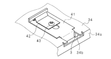
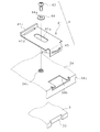
- FIG. 5 and 6 are explanatory views showing the attachment procedure of the clamping member 4.
- 5 shows a state before the clamping member 4 is attached to the back cover 34
- FIG. 6 shows a state after the clamping part 4 is attached to the back cover 34.
- the back cover 34 is provided with through-holes 34b extending inward from the protruding plate 34a at positions corresponding to the respective notches 30 of the light guide plate 3 and having the same width as the notches 30.
- a caulking nut 34c is attached to the back cover 34 so as to penetrate in the thickness direction of the back cover 34 at a position slightly inward (left side) from the through hole 34b.
- the clamping member 4 includes a movable plate piece 41, a leaf spring 42 that is an elastic member, and a bolt 43.
- the movable plate piece 41 is, for example, a metal plate piece formed in a rectangular shape, and has a long hole 41 a that has a width about the same as the outer diameter of the caulking nut 34 c and extends in the longitudinal direction of the movable plate piece 41. It is. Further, one end side of the movable plate piece 41 is provided with a protruding plate piece 41b having a width shorter than the end side and extending slightly in the longitudinal direction of the movable plate piece 41 and then bending and extending vertically. is there.
- a handle plate piece 41c On the other end side of the movable plate piece 41, a handle plate piece 41c extending in the direction opposite to the protruding plate piece 41b is provided. A through-hole 41d that penetrates in the thickness direction of the handle plate piece 41c is provided at the base of the handle plate piece 41c.
- the movable plate piece 41 is placed on the back cover 34 with the protruding plate piece 41b passing through the through hole 34b and the caulking nut 34c fitted into the elongated hole 41a.
- the leaf spring 42 is a rectangular metal plate piece and has a bent portion 42a having a V shape at one end in the longitudinal direction. Further, the leaf spring 42 is provided with a through hole 42b in the vicinity of the other end side (the other end portion in the longitudinal direction) facing the bent portion 42a.
- the leaf spring 42 is fitted to the through hole 41d of the movable plate piece 41 at the end on the side where the bent portion 42a is provided, and the opening of the caulking nut 34c in which the through hole 42b is fitted into the long hole 41a of the movable plate piece 41.
- the clamping member 4 is attached to the back cover 34 by inserting the bolt 43 into the through hole 42 b from above the leaf spring 42 and screwing it into the caulking nut 34 c.
- FIG. 5 and 6 show only the clamping member 4 attached to the right end surface side of the back cover 34, but a caulking nut 34c is also provided at the same position on the left end surface side of the back cover 34.
- the sandwiching member 4 having the configuration described above is attached in a state where the left and right are reversed.
- a procedure for attaching the back cover 34 and the clamping member 4 having the above-described configuration to the light guide plate 3 will be described below.
- the operator When attaching the back cover 34 to the back side of the light guide plate 3, the operator first attaches the two holding members 4 to the back cover 34.
- the operator places the back cover 34 so that the back side (the back side of the surface from which the protruding plate 34 a protrudes) is up.
- the movable plate piece 41 which comprises each clamping member 4 is mounted in a back surface.
- the operator passes the protruding plate piece 41 b of each movable plate piece 41 through the through hole 34 b of the back cover 34, and uses a caulking nut 34 c provided on the back cover 34 to extend the length of each movable plate piece 41.
- the movable plate piece 41 is placed on the back cover 34 through the hole 41a.
- the worker places the plate spring 42 on each movable plate piece 41 so that the bent portion 42a is on the upper side.
- the operator fits the end portion of the leaf spring 42 on the bent portion 42a side into the through hole 41d of each movable plate piece 41, and the through hole 42b of the leaf spring 42 is opened to each caulking nut 34c. Place them in a row.
- the operator inserts the bolts 43 into the through holes 42b from above the respective leaf springs 42, and screws them into the caulking nuts 34c. Thereby, the clamping member 4 is attached to the back cover 34.
- the movable plate piece 41 When attaching the back cover 34 to which the clamping member 4 is attached to the light guide plate 3 as described above, when the movable plate piece 41 is fixed to the back cover 34 and does not move, the operator first loosens the bolt 43 a little.
- the leaf spring 42 is fixed to the back cover 34 with a bolt 43 and a caulking nut 34c at the position of the through hole 42b.
- the movable plate piece 41 is within a range in which the bent portion 42a of the leaf spring 42 can be bent and a range in which the caulking nut 34c is movable along the long hole 41a of the movable plate piece 41 when the bolt 43 is slightly loosened. , It can be moved (slid) along the back cover 34.
- the two movable plate pieces 41 can move in a direction away from each other and a direction approaching (left and right direction).
- the operator holds the handle plate piece 41c of each movable plate piece 41 and moves the two lid members 34 (movable plate pieces 41) in directions away from each other, and then attaches the back cover 34 to the back surface of the light guide plate 3. Attach to.
- the operator brings the protruding plate piece 41b of the two movable plate pieces 41 into contact with the formation portion of the cutout portion 30 (the inner back portion of the cutout portion 30) of the light guide plate 3, and then the handle plate piece 41c. Release your hand.
- the protruding plate pieces 41b of the two movable plate pieces 41 are in contact with the inner back portion (bottom portion) of the cutout portion 30 of the light guide plate 3 on one surface facing each other.
- the two clamping members 4 (movable plate pieces 41) return to the direction approaching each other due to the elasticity of the leaf spring 42, and the light guide plate 3 is clamped by the two clamping members 4.
- the position of the light guide plate 3 in the vertical direction can be fixed.
- the operator fastens the bolt 43 to the caulking nut 34c.
- the notch 30 is provided at a location where the clamping member 4 (movable plate piece 41) clamps the light guide plate 3.
- the protruding plate piece 41 b of the movable plate piece 41 can properly abut the inner back portion of the cutout portion 30 to sandwich the light guide plate 3, and the light guide plate 3 is protruded plate piece at the cutout portion 30. (Locking part) Since it engages with the upper end surface of 41b and stops, it can prevent more that the light-guide plate 3 falls by own weight.
- the vertical position of the light guide plate 3 can be fixed.
- the movable plate piece 41 is made movable by slightly loosening the bolt 43, even if the light guide plate 3 expands due to the heat from the light source unit 2, it expands due to the elasticity of the leaf spring 42. Is absorbed, and the light guide plate 3 can be stably held. Therefore, since the distance between the light guide plate 3 and the two light source units 2 is kept constant, the light emitted from the light guide plate 3 becomes uniform.
- the liquid crystal panel 1 can be irradiated with uniform light, a brightness nonuniformity can be suppressed and display quality is good. Further, since the vertical position of the light guide plate 3 is fixed, even if the light guide plate 3 expands due to heat from the light source unit 2, the light guide plate 3 expands in the vertical direction with respect to the sandwiching member 4. Contact with the light source unit 2 can be prevented, and damage to the light source unit 2 (light source 21) can be avoided.
- the clamping member 4 is provided at a location where the light source section 2 is not disposed opposite to the light guide plate 3, the configuration on the side where the light source section 2 is disposed opposite does not become complicated, and the light source device (back (Light) can be downsized.
- strength which can fully clamp the light-guide plate 3 is realizable.
- two sandwiching members 4 are attached to the center of the left and right end portions of the back cover 34, and the light guide plate 3 is sandwiched from the left and right by the two sandwiching members 4, so that the light guide plate 3 can be stabilized.
- the position of the light guide plate 3 in the vertical direction can be fixed.
- the structure which clamps the light-guide plate 3 in a some position may be sufficient.
- the cutout portion 30 provided in the light guide plate 3 has such a size as to be hidden by the backlight holding portion 33 and the bezel 10 when viewed from the display screen side. Thereby, there is no possibility that the light from the light source part 2 leaks through the notch part 30, and the quality reduction of a display image can be avoided. Further, since the light guide plate 3 is held by the movable plate piece 41 of the holding member 4, the cutout portion 30 provided in the light guide plate 3 is approximately the size (depth) of the movable plate piece 41 (projecting plate piece 41 b). It can be. Therefore, since the depth of the notch portion 30 of the light guide plate 3 can be formed small, the width of the bezel 10 can be formed narrow, and a frame can be formed.
- Embodiment 2 The display device according to Embodiment 2 will be described below.
- the display device according to the second embodiment is different from the display device according to the first embodiment described above in the configuration of the holding member 4 attached to the back cover 34. Therefore, only the clamping member 4 will be described, and the other components will be denoted by the same reference numerals and description thereof will be omitted.
- FIG. 7 is a cross-sectional view taken along the line III-III in FIG. 1
- FIG. 8 is an exploded perspective view showing the configuration of the main part of the display device according to the second embodiment
- FIGS. It is explanatory drawing which shows the attachment procedure of this clamping member.
- the clamping member 4 according to the second embodiment includes a washer 44 and a curved leaf spring 45 instead of the leaf spring 42 according to the first embodiment.
- the curved leaf spring 45 is formed by bending a rectangular metal plate piece.
- the movable plate piece 41 is formed in the same shape as the movable plate piece 41 of the first embodiment described above, and is a curved plate along the longitudinal direction on the outer surface (surface continuous with the upper surface) of the protruding plate piece 41b.
- a spring 45 is provided. Similar to the first embodiment, the movable plate piece 41 is placed on the back cover 34 with the protruding plate piece 41b passing through the through hole 34b and the caulking nut 34c fitted into the elongated hole 41a.
- the washer 44 is a disk-shaped metal plate piece, and a through hole 44a is provided in the center.
- the washer 44 is placed on the movable plate piece 41 in a state where the through hole 44a is continuous with the opening of the crimping nut 34c fitted in the long hole 41a of the movable plate piece 41. Thereafter, the clamping member 4 is attached to the back cover 34 by inserting the bolt 43 into the through hole 44 a from above the washer 44 and screwing it into the caulking nut 34 c.
- the operator fixes the movable plate piece 41 to the back cover 34 in the same manner as in the above-described first embodiment. If it does not move, first loosen the bolt 43 a little.
- the movable plate piece 41 is within the range until the curved leaf spring 45 becomes linear, and the caulking nut 34 c extends along the long hole 41 a of the movable plate piece 41. Within the movable range, it can move along the back cover 34. Also in the second embodiment, the long hole 41a of the movable plate piece 41 guides the movement of the movable plate piece 41 with respect to the caulking nut 34c.
- the operator holds the handle plate piece 41c of each movable plate piece 41 and moves the two lid members 34 (movable plate pieces 41) in directions away from each other, and then attaches the back cover 34 to the back surface of the light guide plate 3. Attach to.
- the operator brings the protruding plate piece 41b of the two movable plate pieces 41 into contact with the formation portion of the cutout portion 30 (the inner back portion of the cutout portion 30) of the light guide plate 3, and then the handle plate piece 41c. Release your hand.
- the two clamping members 4 (movable plate pieces 41) return to the direction approaching each other by the elasticity of the curved leaf spring 45, and the light guide plate 3 is moved by the two clamping members 4.
- the light guide plate 3 can be sandwiched and the position of the light guide plate 3 in the vertical direction can be fixed.
- the operator fastens the bolt 43 to the caulking nut 34c.
- the light guide plate 3 is sandwiched from the left and right directions by the sandwiching member 4 provided on the back cover 34, so that the vertical position of the light guide plate 3 can be fixed. Also in the second embodiment, when the movable plate 41 is moved by slightly loosening the bolts 43, even if the light guide plate 3 is expanded by the heat from the light source unit 2. The expansion is absorbed by the elasticity of the curved leaf spring 45, and the light guide plate 3 can be stably held. Therefore, since the distance between the light guide plate 3 and the two light source parts 2 is kept constant, the same effect as the effect described in the first embodiment, for example, the light emitted from the light guide plate 3 becomes uniform. Is obtained. In the second embodiment, the light guide plate 3 may be sandwiched at a plurality of positions.
- the light source device according to the present invention has been described by taking the liquid crystal panel 1 and a display device including the light source device as an example. (Light source device) Application to a single unit is also possible.
- Liquid crystal panel (display panel) 2 Light source part 3 Light guide plate 4 Clamping member (clamping part) 21 light source 30 notch (engagement part) 33 Backlight holder (holder) 34 Back cover (holding body, support plate) 41 Movable plate (locking part) 42 Leaf spring (elastic member) 45 Curved leaf spring (elastic member) 34b Through-hole 41b Projecting plate piece (locking part)
Landscapes
- Physics & Mathematics (AREA)
- Nonlinear Science (AREA)
- General Physics & Mathematics (AREA)
- Optics & Photonics (AREA)
- Mathematical Physics (AREA)
- Chemical & Material Sciences (AREA)
- Crystallography & Structural Chemistry (AREA)
- Planar Illumination Modules (AREA)
Abstract
小型化が可能であると共に、光源部に対する導光板の位置を適切に保つことができる光源装置及び該光源装置を備えた表示装置を提供する。導光板3の二端面に対して光源21が対向配置されており、導光板3の他の二端面の中央に切り欠き部30が設けてある。また導光板3の一面を覆う裏フタ34には、切り欠き部30に対応する箇所に、導光板3を挟持する挟持部材4が取り付けてある。裏フタ34は、導光板3の一面を支持すると共に、2つの挟持部4にて前記他の二端面を挟持する。
Description
本発明は、エッジライト方式の光源装置、該光源装置を備えた表示装置に関する。
近年、液晶ディスプレイ及び液晶テレビジョン等の表示装置が広く普及している。このような表示装置は、映像を表示する表示面を表側に有し、矩形板状をなす表示パネルと、表示パネルの裏側に配され、表示パネルに対して光を照射する光源ユニットとを備える。光源ユニットには、表示パネルの裏側に導光板及び該導光板を支持する支持体を配し、導光板の端面(側面)側に発光ダイオード(LED)等の光源を配するエッジライト方式がある。エッジライト方式の光源ユニットでは、導光板の端面から入光した光が、導光板内を拡散しながら導光板の一面から出射され、表示パネルへ入射される。
エッジライト方式の光源ユニットにおいて、均一な光を出射するためには、導光板と光源との位置関係がずれることを防ぐ必要があり、導光板と光源との距離を一定に保つことが重要である。
そこで、特許文献1では、LED基板を保持する基板保持部材に、LED基板上のLED光源と導光板との間の距離を規制する規制部を設けることが提案されている。また、光源が搭載された基板(LED基板)と導光板との間に、例えばシリコンゴム製の弾性部材を介在させ、光源と導光板との距離を一定に確保することも行われている。
そこで、特許文献1では、LED基板を保持する基板保持部材に、LED基板上のLED光源と導光板との間の距離を規制する規制部を設けることが提案されている。また、光源が搭載された基板(LED基板)と導光板との間に、例えばシリコンゴム製の弾性部材を介在させ、光源と導光板との距離を一定に確保することも行われている。
しかしながら、表示装置の薄型化及び狭額縁化に伴って光源ユニットの薄型化及び小型化が要望されており、特許文献1に開示されたような規制部を基板保持部材に設けることは困難である。また、一般的に表示装置は立てた状態で使用されることが多く、導光板の上下面側に光源が配置された構成においては、表示パネルの大型化に伴う導光板の大型化により、導光板が自身の重さで下方にずれ、介在させた弾性部材が変形する状況が発生する。更に、エッジライト方式の光源ユニットでは、光源が発光する際に発生する熱が導光板に伝導し、光源からの熱により導光板が膨張することがある。このような熱膨張と、導光板の重さによる位置ズレとが同時的に発生した場合、導光板が光源に接触して光源を破損する虞がある。
本発明は、斯かる事情に鑑みてなされたものである。そして、その目的とするところは、小型化が可能であると共に、光源部に対する導光板の位置を適切に保つことが可能な光源装置及び該光源装置を備えた表示装置を提供することにある。
本発明に係る光源装置は、矩形の導光板と、該導光板の対向する二端面に対向配置された光源部と、該光源部及び前記導光板を保持する保持体とを備え、前記二端面から前記導光板に入射された前記光源部からの光を前記導光板の一面から出射する光源装置において、前記保持体に取り付けてあり、前記導光板を他の二端面で挟持する挟持部を備えることを特徴とする。
本発明においては、光源部が対向配置されていない二端面にて導光板を挟持するので、光源部に対する導光板の位置を安定に保つことができる。よって、均一な光を出射できる光源装置を実現できる。また、光源部が対向配置されていない二端面側に挟持部材が設けられるので、光源部が対向配置されている二端面側の構成が煩雑とならず、光源装置の小型化が可能となる。
本発明に係る光源装置は、前記挟持部のそれぞれは、互いに近付く方向に付勢する弾性部材を有することを特徴とする。
本発明においては、弾性部材によって導光板を挟持するので、例えば、光源部からの熱によって導光板が膨張した場合であっても、導光板を安定して挟持できる。よって、導光板の位置を安定に保つことができる。
本発明に係る光源装置は、前記導光板は、前記他の二端面の対向する位置に、前記挟持部と係合する係合部をそれぞれ有し、前記挟持部は、前記係合部のそれぞれに係止する係止部を有することを特徴とする。
本発明においては、導光板及び挟持部が互いに係合(係止)するので、光源部に対する導光板の位置をより安定に保つことができる。
本発明に係る光源装置は、前記係合部は、前記導光板を厚み方向に貫通する切り欠き部であり、前記保持体は、前記導光板を一面で支持する支持板を有し、該支持板は、前記切り欠き部に対応する位置で貫通する貫通孔を有し、前記係止部は、前記支持板の他面の前記貫通孔に対応する位置に、前記他面に沿って移動可能に取り付けられた可動板片と、該可動板片から突設され、前記貫通孔を通して前記保持体内に延び、前記切り欠き部の内奥部に一面が当接する突設板片とを有することを特徴とする。
本発明においては、導光板に設けられた切り欠き部に、導光板を挟持する挟持部材の係止部が係止するので、光源部に対する導光板の位置をより安定に保つことができる。
本発明に係る光源装置は、前記可動板片は、前記支持板の他面に沿って配置された板片と、該板片を、対向する前記挟持部の可動板片に近付く方向に付勢する弾性部材とを有することを特徴とする。
本発明においては、挟持部(係止部)を構成する可動板片が、弾性部材によって互いに近付く方向に付勢されており、弾性部材によって導光板を挟持するので、導光板を安定して挟持でき、導光板の位置を安定に保つことができる。
本発明に係る光源装置は、前記挟持部は、複数箇所に設けてあることを特徴とする。
本発明においては、導光板を複数箇所で挟持することにより、光源部に対する導光板の位置をより強固に固定することができる。
本発明においては、導光板を複数箇所で挟持することにより、光源部に対する導光板の位置をより強固に固定することができる。
本発明に係る表示装置は、上述したいずれかの光源装置と、該光源装置から出射される光を用いて映像を表示する表示パネルとを備えることを特徴とする。
本発明においては、導光板の位置を安定に保つことができる光源装置を用いることにより、光源装置から出射される均一な光を用いた映像の表示が可能となり、表示品質が向上する。
本発明においては、導光板の位置を安定に保つことができる光源装置を用いることにより、光源装置から出射される均一な光を用いた映像の表示が可能となり、表示品質が向上する。
本発明によれば、導光板の対向する二端面に光源部が対向配置されている光源装置において、導光板を他の二端面で挟持するので、導光板と各光源部との距離を一定に保つことができ、均一な光の出射が可能となる。また、導光板を挟持する挟持部が、他の二端面側に設けてあるので、光源部が対向配置してある二端面側の構成が単純化でき、光源装置の小型化が可能となる。よって、光源装置のサイズに制限がある場合であっても、導光板の位置を適切に保つことができる。
以下に、本発明に係る光源装置及び該光源装置を備えた表示装置について、その実施の形態を示す図面を用いて具体的に説明する。
(実施の形態1)
図1は、実施の形態1に係る表示装置の正面図、図2は、図1中のII-II線による縦断面図、図3は、図1中のIII-III線による横断面図、図4は、実施の形態1に係る表示装置の要部構成を示す分解斜視図である。本実施の形態1の表示装置は、エッジライト方式の光源装置を備えた液晶表示装置である。本実施の形態1の表示装置は、矩形板状の液晶パネル(表示パネル)1と、液晶パネル1に光を照射する光源装置とを備える。
図1は、実施の形態1に係る表示装置の正面図、図2は、図1中のII-II線による縦断面図、図3は、図1中のIII-III線による横断面図、図4は、実施の形態1に係る表示装置の要部構成を示す分解斜視図である。本実施の形態1の表示装置は、エッジライト方式の光源装置を備えた液晶表示装置である。本実施の形態1の表示装置は、矩形板状の液晶パネル(表示パネル)1と、液晶パネル1に光を照射する光源装置とを備える。
液晶パネル1は例えば、複数の液晶素子を2次元マトリクス状に配列して構成されている。液晶パネル1の周縁は表示画面側からベゼル10によって覆われている。光源装置は、2つの光源部2及び導光板3等を備える。
それぞれの光源部2は、短冊状の基板22と、基板22の長手方向に沿って実装された光源21と、基板22及び光源21を保持する角柱状の保持板23とを有する。光源21は、例えば、発光ダイオード(LED:Light Emitting Diode)であり、複数の発光ダイオードが基板22の長手方向に沿って実装されている。光源21は、発光ダイオードのほか、冷陰極蛍光ランプ(CCFL:Cold Cathode Fluorescent Lamp)、外部電極蛍光ランプ(EEFL:External Electrode Fluorescent Lamp)、熱陰極蛍光ランプ(HCFL:Hot Cathode Fluorescent Lamp)等であってもよい。
それぞれの光源部2は、短冊状の基板22と、基板22の長手方向に沿って実装された光源21と、基板22及び光源21を保持する角柱状の保持板23とを有する。光源21は、例えば、発光ダイオード(LED:Light Emitting Diode)であり、複数の発光ダイオードが基板22の長手方向に沿って実装されている。光源21は、発光ダイオードのほか、冷陰極蛍光ランプ(CCFL:Cold Cathode Fluorescent Lamp)、外部電極蛍光ランプ(EEFL:External Electrode Fluorescent Lamp)、熱陰極蛍光ランプ(HCFL:Hot Cathode Fluorescent Lamp)等であってもよい。
導光板3は、透明度の高いアクリル樹脂、ポリカーボネート樹脂等の合成樹脂製であり、矩形板状に形成されている。導光板3の一面には光学シート31が被着されており、他面には反射シート32が被着されている。反射シート32は、高反射性を有する合成樹脂製のシートであり、反射シート32の導光板3に対向する面に、反射性のよい塗料が塗布されていてもよい。光学シート31は、例えば拡散シート、プリズムシート及び偏光シート等が積層されたシートであり、入射された光を均一な平面光として出射する。拡散シートは、例えば、PET(ポリエチレンテレフタレート)製フィルム又はポリカーボネート樹脂製フィルムであり、入射された光を拡散させる機能を有する。プリズムシートは、例えば、ポリエステル製のシート材の片面にアクリル樹脂で規則的なプリズムパターンを成形して構成されている。偏光シートは、例えば、ポリエチレンナフタレート製フィルムであり、入射された光を直線偏光に変換する機能を有する。
上述した構成の光源部2は、導光板3の上端面及び下端面のそれぞれに光源21からの光が入射するように対向配置されている。裏フタ(支持板)34は、光学シート31及び反射シート32が被覆された導光板3(以下では省略して導光板3ということもある)よりも若干大きい矩形平板であり、両端辺からそれぞれ同じ向きに垂直に立ち上がる突出板34aが設けてある。裏フタ34は、突出板34aが設けられた側の一面で導光板3及び光源部2を反射シート32側から支持する。バックライト保持部33は、導光板3よりも若干大きい矩形枠状に形成されており、導光板3の周縁を光学シート31側から覆う。なお、バックライト保持部33は、導光板3及び光源部2が裏フタ34にて支持された状態で、導光板3の周縁を光学シート31側から覆う。このように光源部2及び導光板3は、バックライト保持部33及び裏フタ34にて保持されており、バックライト保持部33及び裏フタ34は、光源装置を保持する保持体として機能する。
上述した構成により、光源部2、導光板3、光学シート31、反射シート32、バックライト保持部33及び裏フタ34によって、液晶パネル1に光を照射する光源装置(バックライト)が実現される。
液晶パネル1は、導光板3と同程度の大きさの矩形板状に形成されており、一面を導光板3(光学シート31)に対向させて、バックライト保持部33に載置される。ベゼル10は、バックライト保持部33よりも若干大きく同様の矩形枠状に形成されており、光源装置(バックライト保持部33)に載置された液晶パネル1の周縁を外側(表示画面側)から覆う。これにより、図1~3に示すような表示装置が構成される。
液晶パネル1は、導光板3と同程度の大きさの矩形板状に形成されており、一面を導光板3(光学シート31)に対向させて、バックライト保持部33に載置される。ベゼル10は、バックライト保持部33よりも若干大きく同様の矩形枠状に形成されており、光源装置(バックライト保持部33)に載置された液晶パネル1の周縁を外側(表示画面側)から覆う。これにより、図1~3に示すような表示装置が構成される。
次に、光源装置内における光の経路について説明する。
光源部2(光源21)から出射した光は、導光板3に上下端面からそれぞれ入射し、反射シート32に反射した後、導光板3及び光学シート31を通過し、平面光として液晶パネル1に照射される。なお、導光板3の光学シート31が設けられる面に、出射する光を液晶パネル1方向へ適切に進行させるようなパターンを形成してもよく、この場合、導光板3から出射される光がより均一に光学シート31に伝達できる。
光源部2(光源21)から出射した光は、導光板3に上下端面からそれぞれ入射し、反射シート32に反射した後、導光板3及び光学シート31を通過し、平面光として液晶パネル1に照射される。なお、導光板3の光学シート31が設けられる面に、出射する光を液晶パネル1方向へ適切に進行させるようなパターンを形成してもよく、この場合、導光板3から出射される光がより均一に光学シート31に伝達できる。
本実施の形態1では、図4に示すように、導光板3に、光源部2が対向配置されていない端面(図1においては左端面及び右端面)のそれぞれの中央に矩形断面を有する切り欠き部30が設けてある。また裏フタ34には、導光板3の切り欠き部30のそれぞれに対応する位置に挟持部材(挟持部)4が取り付けてある。導光板3は、切り欠き部(係合部)30の形成箇所で挟持部材4にて固定(挟持)される。
図5及び図6は、挟持部材4の取り付け手順を示す説明図である。なお、図5には、挟持部材4が裏フタ34に取り付けられる前の状態を、図6には、挟持部4が裏フタ34に取り付けられた後の状態をそれぞれ示している。
裏フタ34には、導光板3の切り欠き部30のそれぞれに対応する位置に、切り欠き部30と同程度の幅で、突出板34aから内向きに伸びる貫通孔34bが設けてある。また裏フタ34には、貫通孔34bから内側(左側)に少し離れた位置に、裏フタ34の厚さ方向に貫通させてカシメナット34cが取り付けてある。
裏フタ34には、導光板3の切り欠き部30のそれぞれに対応する位置に、切り欠き部30と同程度の幅で、突出板34aから内向きに伸びる貫通孔34bが設けてある。また裏フタ34には、貫通孔34bから内側(左側)に少し離れた位置に、裏フタ34の厚さ方向に貫通させてカシメナット34cが取り付けてある。
挟持部材4は、可動板片41、弾性部材である板ばね42及びボルト43を備える。可動板片41は、例えば矩形状に形成された金属板片であり、中央に、カシメナット34cの外径と同程度の幅を有し、可動板片41の長手方向に伸びる長孔41aが設けてある。また可動板片41の一方の端辺には、該端辺よりも短い幅を有し、可動板片41の長手方向に若干伸びた後に垂直に屈曲して伸びる突設板片41bが設けてある。また可動板片41の他方の端辺には、突設板片41bとは逆向きに伸びる取っ手板片41cが設けてある。取っ手板片41cの基部には、取っ手板片41cの厚み方向に貫通する貫通孔41dが設けてある。
可動板片41は、突設板片41bが貫通孔34bを通り、カシメナット34cが長孔41aに嵌まった状態で裏フタ34に載置される。
可動板片41は、突設板片41bが貫通孔34bを通り、カシメナット34cが長孔41aに嵌まった状態で裏フタ34に載置される。
板ばね42は、矩形状の金属板片であり、長手方向の一端部にV字形状をなす屈曲部42aを有する。また板ばね42には、屈曲部42aに対向する他端側(長手方向の他端部)の近傍に貫通孔42bが設けてある。板ばね42は、屈曲部42aが設けてある側の端部を可動板片41の貫通孔41dに嵌合し、貫通孔42bが可動板片41の長孔41aに嵌められたカシメナット34cの開口に連なる状態で可動板片41に載置される。その後、ボルト43が板ばね42の上から貫通孔42bに挿入され、カシメナット34cに螺嵌されることにより、挟持部材4が裏フタ34に取り付けられる。
なお、図5及び図6には、裏フタ34の右端面側に取り付けられた挟持部材4のみを示すが、裏フタ34の左端面側にも同様の位置にカシメナット34cが設けてあり、同様の構成の挟持部材4が左右反転させた状態で取り付けられている。
以下に、上述した構成の裏フタ34及び挟持部材4を導光板3に取り付ける手順について説明する。導光板3の背面側に裏フタ34を取り付ける場合、作業者はまず、裏フタ34に2つの挟持部材4をそれぞれ取り付ける。
2つの挟持部材4を裏フタ34に取り付ける場合、作業者は、裏フタ34を背面側(突出板34aが突出される面の裏面側)が上になるように載置し、裏フタ34の背面に、それぞれの挟持部材4を構成する可動板片41を載置する。具体的には、作業者は、それぞれの可動板片41の突設板片41bを裏フタ34の貫通孔34bに通し、裏フタ34に設けられたカシメナット34cをそれぞれの可動板片41の長孔41aに通して可動板片41を裏フタ34に載置する。
2つの挟持部材4を裏フタ34に取り付ける場合、作業者は、裏フタ34を背面側(突出板34aが突出される面の裏面側)が上になるように載置し、裏フタ34の背面に、それぞれの挟持部材4を構成する可動板片41を載置する。具体的には、作業者は、それぞれの可動板片41の突設板片41bを裏フタ34の貫通孔34bに通し、裏フタ34に設けられたカシメナット34cをそれぞれの可動板片41の長孔41aに通して可動板片41を裏フタ34に載置する。
次に、作業者は、それぞれの可動板片41の上に、板ばね42を屈曲部42aが上側になるように載置する。具体的には、作業者は、板ばね42の屈曲部42a側の端部をそれぞれの可動板片41の貫通孔41dに嵌合し、板ばね42の貫通孔42bをそれぞれのカシメナット34cの開口に連なるように載置する。そして、作業者は、ボルト43をそれぞれの板ばね42の上から貫通孔42bに挿入し、カシメナット34cに螺嵌する。これにより、挟持部材4が裏フタ34に取り付けられる。
上述のように挟持部材4が取り付けられた裏フタ34を導光板3に取り付ける場合、可動板片41が裏フタ34に固定されて動かない場合、作業者はまずボルト43を少しゆるめる。板ばね42は、貫通孔42bの位置でボルト43及びカシメナット34cにて裏フタ34に固定される。一方、可動板片41は、ボルト43が少しゆるめられた場合、板ばね42の屈曲部42aが屈曲可能な範囲内及びカシメナット34cが可動板片41の長孔41aに沿って移動可能な範囲内において、裏フタ34に沿って移動(スライド)可能となる。なお、可動板片41の長孔41aが、カシメナット34cに対する可動板片41の移動をガイドするので、2つの可動板片41は、互いに離れる方向及び近付く方向(左右方向)に移動可能となる。
作業者は、それぞれの可動板片41の取っ手板片41cを保持し、2つの挟持部材4(可動板片41)を互いに離れる方向に移動させた状態で、裏フタ34を導光板3の背面に取り付ける。作業者は、2つの可動板片41の突設板片41bを、導光板3の切り欠き部30の形成箇所(切り欠き部30の内奥部)に当接させた後、取っ手板片41cから手を離す。なお、2つの可動板片41の突設板片41bは、互いに対向する一面にて導光板3の切り欠き部30の内奥部(底部)に当接する。
作業者が取っ手板片41cから手を離した後、2つの挟持部材4(可動板片41)は板ばね42の弾性によって互いに近付く方向に戻り、2つの挟持部材4にて導光板3を挟持することができ、導光板3の上下方向の位置を固定することができる。なお、可動板片41を裏フタ34に固定する場合、作業者は、ボルト43をカシメナット34cに締め付けておく。
本実施の形態1では、挟持部材4(可動板片41)が導光板3を挟持する箇所に切り欠き部30が設けてある。これにより、可動板片41の突設板片41bが切り欠き部30の内奥部に適切に当接して導光板3を挟持できるとともに、導光板3が切り欠き部30にて突設板片(係止部)41bの上端面に係合して止まるので、導光板3が自身の重みで下がることをより防止できる。
本実施の形態1では、挟持部材4(可動板片41)が導光板3を挟持する箇所に切り欠き部30が設けてある。これにより、可動板片41の突設板片41bが切り欠き部30の内奥部に適切に当接して導光板3を挟持できるとともに、導光板3が切り欠き部30にて突設板片(係止部)41bの上端面に係合して止まるので、導光板3が自身の重みで下がることをより防止できる。
本実施の形態1では、裏フタ34に設けられた挟持部材4にて導光板3が左右方向から挟持されるので、導光板3の上下位置を固定できる。なお、ボルト43を少しゆるめて可動板片41を移動可能な状態としておいた場合には、光源部2からの熱によって導光板3が膨張した場合であっても、板ばね42の弾性によって膨張が吸収され、導光板3を安定して保持できる。よって、導光板3と2つの光源部2との距離が一定に保たれるので、導光板3から出射される光が均一になる。そして、このような光源装置を用いて表示装置を構成した場合には、均一な光にて液晶パネル1を照射できるので、輝度ムラを抑制でき、表示品質がよい。また、導光板3の上下位置が固定されるので、光源部2からの熱によって導光板3が膨張した場合であっても、挟持部材4に対して上下方向に膨張するので、導光板3が光源部2に接触することを防止でき、光源部2(光源21)が破損することを回避できる。更に、導光板3に対して、光源部2が対向配置されていない箇所に挟持部材4が設けられるので、光源部2が対向配置されている側の構成が煩雑とならず、光源装置(バックライト)の小型化が可能となる。本実施の形態1では、挟持部材4の各部(可動板片41及び板ばね42)が金属製であるので、導光板3を十分に挟持できる強度を実現できる。
本実施の形態1では、裏フタ34の左右端部の中央に2つの挟持部材4が取り付けられ、2つの挟持部材4にて導光板3を左右から挟持するので、導光板3を安定して挟持でき、導光板3の上下方向の位置を固定できる。なお、複数の位置で導光板3を挟持する構成でもよい。
本実施の形態1において、導光板3に設ける切り欠き部30は、表示画面側から見た場合に、バックライト保持部33及びベゼル10によって隠れる程度の大きさとしてある。これにより、光源部2からの光が切り欠き部30を通して漏れる虞がなく、表示画像の品質低下を回避できる。また挟持部材4の可動板片41にて導光板3を挟持するので、導光板3に設ける切り欠き部30は、可動板片41(突設板片41b)の厚み程度の大きさ(奥行き)とすることができる。よって、導光板3の切り欠き部30の奥行きを小さく形成できるので、ベゼル10の幅も細く形成でき、挟額縁化が可能である。
(実施の形態2)
以下に、実施の形態2に係る表示装置について説明する。本実施の形態2の表示装置は、裏フタ34に取り付けられる挟持部材4の構成が、上述の実施の形態1の表示装置と相異する。従って、挟持部材4についてのみ説明し、その他の構成については同一の符号を付して説明を省略する。
以下に、実施の形態2に係る表示装置について説明する。本実施の形態2の表示装置は、裏フタ34に取り付けられる挟持部材4の構成が、上述の実施の形態1の表示装置と相異する。従って、挟持部材4についてのみ説明し、その他の構成については同一の符号を付して説明を省略する。
図7は、図1中のIII-III線による横断面図、図8は、実施の形態2に係る表示装置の要部構成を示す分解斜視図、図9及び図10は、実施の形態2の挟持部材4の取り付け手順を示す説明図である。
本実施の形態2の挟持部材4は、実施の形態1における板ばね42の代わりにワッシャ44及び湾曲板ばね45を備える。
湾曲板ばね45は、矩形状の金属板片を湾曲して形成されている。可動板片41は、上述の実施の形態1の可動板片41と同様の形状に形成されており、突設板片41bの外側の面(上面に連なる面)に長手方向に沿って湾曲板ばね45が設けてある。可動板片41は、上述の実施の形態1と同様に、突設板片41bが貫通孔34bを通り、カシメナット34cが長孔41aに嵌まった状態で裏フタ34に載置される。
湾曲板ばね45は、矩形状の金属板片を湾曲して形成されている。可動板片41は、上述の実施の形態1の可動板片41と同様の形状に形成されており、突設板片41bの外側の面(上面に連なる面)に長手方向に沿って湾曲板ばね45が設けてある。可動板片41は、上述の実施の形態1と同様に、突設板片41bが貫通孔34bを通り、カシメナット34cが長孔41aに嵌まった状態で裏フタ34に載置される。
ワッシャ44は、円板状の金属板片であり、中央に貫通孔44aが設けてある。ワッシャ44は、貫通孔44aが可動板片41の長孔41aに嵌められたカシメナット34cの開口に連なる状態で可動板片41に載置される。その後、ボルト43がワッシャ44の上から貫通孔44aに挿入され、カシメナット34cに螺嵌されることにより、挟持部材4が裏フタ34に取り付けられる。
以下に、本実施の形態2において、裏フタ34及び挟持部材4を導光板3に取り付ける手順について説明する。本実施の形態2においても、導光板3の背面側に裏フタ34を取り付ける場合、作業者はまず、裏フタ34に2つの挟持部材4をそれぞれ取り付ける。
2つの挟持部材4を裏フタ34に取り付ける場合、作業者は、上述の実施の形態1での手順と同様に、裏フタ34の背面(突出板34aが突出される面の裏面)に、それぞれの挟持部材4を構成する可動板片41を載置する。なおこのとき、可動板片41の突設板片41bに設けられた湾曲板ばね45は、裏フタ34(突出板34a)に当接していなくてもよい。次に、作業者は、それぞれの可動板片41の上に、貫通孔44aがそれぞれのカシメナット34cの開口に連なるようにワッシャ44を載置する。そして、作業者は、ボルト43をワッシャ44の上から貫通孔44aに挿入し、カシメナット34cに螺嵌する。これにより、挟持部材4が裏フタ34に取り付けられる。
上述のように挟持部材4が取り付けられた裏フタ34を導光板3に取り付ける場合、作業者は、上述の実施の形態1での手順と同様に、可動板片41が裏フタ34に固定されて動かない場合、まずボルト43を少しゆるめる。本実施の形態2では、可動板片41は、ボルト43が少しゆるめられた場合、湾曲板ばね45が直線状となるまでの範囲内及びカシメナット34cが可動板片41の長孔41aに沿って移動可能な範囲内において、裏フタ34に沿って移動可能となる。本実施の形態2においても、可動板片41の長孔41aが、カシメナット34cに対する可動板片41の移動をガイドする。
作業者は、それぞれの可動板片41の取っ手板片41cを保持し、2つの挟持部材4(可動板片41)を互いに離れる方向に移動させた状態で、裏フタ34を導光板3の背面に取り付ける。作業者は、2つの可動板片41の突設板片41bを、導光板3の切り欠き部30の形成箇所(切り欠き部30の内奥部)に当接させた後、取っ手板片41cから手を離す。
作業者が取っ手板片41cから手を離した後、2つの挟持部材4(可動板片41)は湾曲板ばね45の弾性によって互いに近付く方向に戻り、2つの挟持部材4にて導光板3を挟持することができ、導光板3の上下方向の位置を固定することができる。なお、可動板片41を裏フタ34に固定する場合、作業者は、ボルト43をカシメナット34cに締め付けておく。
上述の構成により、本実施の形態2においても、裏フタ34に設けられた挟持部材4にて導光板3が左右方向から挟持されるので、導光板3の上下位置を固定できる。また、本実施の形態2においても、ボルト43を少しゆるめて可動板片41を移動可能な状態としておいた場合には、光源部2からの熱によって導光板3が膨張した場合であっても、湾曲板ばね45の弾性によって膨張が吸収され、導光板3を安定して保持できる。よって、導光板3と2つの光源部2との距離が一定に保たれるので、導光板3から出射される光が均一になる等、上述の実施の形態1で説明した効果と同様の効果が得られる。
また、本実施の形態2においても、複数の位置で導光板3を挟持する構成としてもよい。
また、本実施の形態2においても、複数の位置で導光板3を挟持する構成としてもよい。
上述の実施の形態1,2では、本発明に係る光源装置について、液晶パネル1及び光源装置を備えた表示装置を例に説明したが、本発明は、液晶パネル1を有していない照明装置(光源装置)単体への適用も可能である。
今回開示された実施の形態は、全ての点で例示であって、制限的なものではないと考えられるべきである。本発明の範囲は、上述した意味ではなく、請求の範囲によって示され、請求の範囲と均等の意味及び範囲内での全ての変更が含まれることが意図される。また、各実施の形態で記載されている技術的特徴は、お互いに組み合わせることが可能である。
1 液晶パネル(表示パネル)
2 光源部
3 導光板
4 挟持部材(挟持部)
21 光源
30 切り欠き部(係合部)
33 バックライト保持部(保持体)
34 裏フタ(保持体、支持板)
41 可動板片(係止部)
42 板ばね(弾性部材)
45 湾曲板ばね(弾性部材)
34b 貫通孔
41b 突設板片(係止部)
2 光源部
3 導光板
4 挟持部材(挟持部)
21 光源
30 切り欠き部(係合部)
33 バックライト保持部(保持体)
34 裏フタ(保持体、支持板)
41 可動板片(係止部)
42 板ばね(弾性部材)
45 湾曲板ばね(弾性部材)
34b 貫通孔
41b 突設板片(係止部)
Claims (7)
- 矩形の導光板と、該導光板の対向する二端面に対向配置された光源部と、該光源部及び前記導光板を保持する保持体とを備え、前記二端面から前記導光板に入射された前記光源部からの光を前記導光板の一面から出射する光源装置において、
前記保持体に取り付けてあり、前記導光板を他の二端面で挟持する挟持部を備えることを特徴とする光源装置。 - 前記挟持部のそれぞれは、互いに近付く方向に付勢する弾性部材を有することを特徴とする請求項1に記載の光源装置。
- 前記導光板は、前記他の二端面の対向する位置に、前記挟持部と係合する係合部をそれぞれ有し、
前記挟持部は、前記係合部のそれぞれに係止する係止部を有する
ことを特徴とする請求項1又は2に記載の光源装置。 - 前記係合部は、前記導光板を厚み方向に貫通する切り欠き部であり、
前記保持体は、前記導光板を一面で支持する支持板を有し、
該支持板は、前記切り欠き部に対応する位置で貫通する貫通孔を有し、
前記係止部は、
前記支持板の他面の前記貫通孔に対応する位置に、前記他面に沿って移動可能に取り付けられた可動板片と、
該可動板片から突設され、前記貫通孔を通して前記保持体内に延び、前記切り欠き部の内奥部に一面が当接する突設板片とを有する
ことを特徴とする請求項3に記載の光源装置。 - 前記可動板片は、
前記支持板の他面に沿って配置された板片と、
該板片を、対向する前記挟持部の可動板片に近付く方向に付勢する弾性部材と
を有することを特徴とする請求項4に記載の光源装置。 - 前記挟持部は、複数箇所に設けてあることを特徴とする請求項1から5までのいずれかひとつに記載の光源装置。
- 請求項1から6までのいずれかひとつに記載の光源装置と、
該光源装置から出射される光を用いて映像を表示する表示パネルと
を備えることを特徴とする表示装置。
Priority Applications (1)
| Application Number | Priority Date | Filing Date | Title |
|---|---|---|---|
| US14/896,516 US9715060B2 (en) | 2013-06-27 | 2014-06-16 | Light source device and display apparatus |
Applications Claiming Priority (2)
| Application Number | Priority Date | Filing Date | Title |
|---|---|---|---|
| JP2013135407 | 2013-06-27 | ||
| JP2013-135407 | 2013-06-27 |
Publications (1)
| Publication Number | Publication Date |
|---|---|
| WO2014208385A1 true WO2014208385A1 (ja) | 2014-12-31 |
Family
ID=52141727
Family Applications (1)
| Application Number | Title | Priority Date | Filing Date |
|---|---|---|---|
| PCT/JP2014/065899 Ceased WO2014208385A1 (ja) | 2013-06-27 | 2014-06-16 | 光源装置及び表示装置 |
Country Status (2)
| Country | Link |
|---|---|
| US (1) | US9715060B2 (ja) |
| WO (1) | WO2014208385A1 (ja) |
Cited By (2)
| Publication number | Priority date | Publication date | Assignee | Title |
|---|---|---|---|---|
| US9933561B2 (en) * | 2015-08-18 | 2018-04-03 | Shenzhen China Star Optoelectronics Technology Co., Ltd. | Liquid crystal display and backlight module thereof |
| WO2018180953A1 (ja) * | 2017-03-31 | 2018-10-04 | パナソニックIpマネジメント株式会社 | 画像表示装置 |
Families Citing this family (5)
| Publication number | Priority date | Publication date | Assignee | Title |
|---|---|---|---|---|
| US9927649B2 (en) * | 2013-11-05 | 2018-03-27 | Nanosys, Inc. | Backlight unit for display devices |
| CN211694513U (zh) * | 2020-02-28 | 2020-10-16 | 漳州立达信光电子科技有限公司 | 面板灯 |
| DE102020216019A1 (de) | 2020-09-01 | 2022-03-03 | Continental Automotive Gmbh | Beleuchtungseinheit mit einer Zentriereinrichtung für einen Lichtleiter |
| DE102020216016B3 (de) | 2020-09-01 | 2022-01-27 | Continental Automotive Gmbh | Beleuchtungseinheit mit einer Zentriereinrichtung für einen Lichtleiter |
| JP7789535B2 (ja) * | 2021-12-08 | 2025-12-22 | シャープ株式会社 | 表示装置 |
Citations (2)
| Publication number | Priority date | Publication date | Assignee | Title |
|---|---|---|---|---|
| WO2011013406A1 (ja) * | 2009-07-30 | 2011-02-03 | シャープ株式会社 | エッジライト式照明装置、液晶表示装置及びテレビ受信装置 |
| WO2012002074A1 (ja) * | 2010-06-30 | 2012-01-05 | シャープ株式会社 | 照明装置、表示装置及びテレビ受信装置 |
Family Cites Families (1)
| Publication number | Priority date | Publication date | Assignee | Title |
|---|---|---|---|---|
| WO2011093136A1 (ja) | 2010-01-26 | 2011-08-04 | シャープ株式会社 | 照明装置、表示装置およびテレビ受信装置 |
-
2014
- 2014-06-16 US US14/896,516 patent/US9715060B2/en not_active Expired - Fee Related
- 2014-06-16 WO PCT/JP2014/065899 patent/WO2014208385A1/ja not_active Ceased
Patent Citations (2)
| Publication number | Priority date | Publication date | Assignee | Title |
|---|---|---|---|---|
| WO2011013406A1 (ja) * | 2009-07-30 | 2011-02-03 | シャープ株式会社 | エッジライト式照明装置、液晶表示装置及びテレビ受信装置 |
| WO2012002074A1 (ja) * | 2010-06-30 | 2012-01-05 | シャープ株式会社 | 照明装置、表示装置及びテレビ受信装置 |
Cited By (5)
| Publication number | Priority date | Publication date | Assignee | Title |
|---|---|---|---|---|
| US9933561B2 (en) * | 2015-08-18 | 2018-04-03 | Shenzhen China Star Optoelectronics Technology Co., Ltd. | Liquid crystal display and backlight module thereof |
| WO2018180953A1 (ja) * | 2017-03-31 | 2018-10-04 | パナソニックIpマネジメント株式会社 | 画像表示装置 |
| US10514576B2 (en) | 2017-03-31 | 2019-12-24 | Panasonic Intellectual Property Management Co., Ltd. | Image display apparatus |
| JPWO2018180953A1 (ja) * | 2017-03-31 | 2020-02-06 | パナソニックIpマネジメント株式会社 | 画像表示装置 |
| JP7033723B2 (ja) | 2017-03-31 | 2022-03-11 | パナソニックIpマネジメント株式会社 | 画像表示装置 |
Also Published As
| Publication number | Publication date |
|---|---|
| US9715060B2 (en) | 2017-07-25 |
| US20160139329A1 (en) | 2016-05-19 |
Similar Documents
| Publication | Publication Date | Title |
|---|---|---|
| US8704974B2 (en) | Backlight assembly comprising a light-sourcing unit fixing frame with a lateral extension portion and a fixing protrusion which interlocks the light-sourcing unit fixing frame to a housing | |
| EP1785764B1 (en) | Display unit with heat dissipation capability | |
| JP6343614B2 (ja) | 光源装置及び表示装置 | |
| JP6006878B2 (ja) | 光源装置及び表示装置 | |
| CN104685555A (zh) | 显示装置、液晶显示装置 | |
| US9715060B2 (en) | Light source device and display apparatus | |
| JP5064602B2 (ja) | 表示装置 | |
| WO2012039196A1 (ja) | 照明装置、表示装置およびテレビ受信装置 | |
| WO2010150883A1 (ja) | 光源装置、画像表示装置及びテレビ受像装置 | |
| JP2014165116A (ja) | 照明装置および表示装置 | |
| US10180533B2 (en) | Light source module and display apparatus | |
| JP4618043B2 (ja) | 面発光装置 | |
| US9739932B2 (en) | Light source module and display apparatus | |
| US20090073346A1 (en) | Backlight and liquid crystal display apparatus | |
| JP4781483B1 (ja) | 導光板装置、光源装置、表示装置及びテレビ受像装置 | |
| JP6240773B2 (ja) | 光源装置及び表示装置 | |
| WO2011046133A1 (ja) | 光源装置及び表示装置 | |
| US10302999B2 (en) | Light source device and display device | |
| US10613361B2 (en) | Display device | |
| JP2018173502A (ja) | 表示装置 | |
| JP2012212527A (ja) | 表示装置 | |
| KR20180138233A (ko) | 백라이트 장치 | |
| US20100073592A1 (en) | Backlight unit and liquid crystal display apparatus | |
| JP2014235327A (ja) | 表示装置 |
Legal Events
| Date | Code | Title | Description |
|---|---|---|---|
| 121 | Ep: the epo has been informed by wipo that ep was designated in this application |
Ref document number: 14816974 Country of ref document: EP Kind code of ref document: A1 |
|
| WWE | Wipo information: entry into national phase |
Ref document number: 14896516 Country of ref document: US |
|
| NENP | Non-entry into the national phase |
Ref country code: DE |
|
| 122 | Ep: pct application non-entry in european phase |
Ref document number: 14816974 Country of ref document: EP Kind code of ref document: A1 |
|
| NENP | Non-entry into the national phase |
Ref country code: JP |