WO2014207995A1 - ワイヤレス送電装置およびその制御方法 - Google Patents
ワイヤレス送電装置およびその制御方法 Download PDFInfo
- Publication number
- WO2014207995A1 WO2014207995A1 PCT/JP2014/002759 JP2014002759W WO2014207995A1 WO 2014207995 A1 WO2014207995 A1 WO 2014207995A1 JP 2014002759 W JP2014002759 W JP 2014002759W WO 2014207995 A1 WO2014207995 A1 WO 2014207995A1
- Authority
- WO
- WIPO (PCT)
- Prior art keywords
- signal
- temperature
- power transmission
- power
- difference
- Prior art date
- Legal status (The legal status is an assumption and is not a legal conclusion. Google has not performed a legal analysis and makes no representation as to the accuracy of the status listed.)
- Ceased
Links
Images


Classifications
-
- H—ELECTRICITY
- H02—GENERATION; CONVERSION OR DISTRIBUTION OF ELECTRIC POWER
- H02J—ELECTRIC POWER NETWORKS; CIRCUIT ARRANGEMENTS OR SYSTEMS FOR SUPPLYING OR DISTRIBUTING ELECTRIC POWER; SYSTEMS FOR STORING ELECTRIC ENERGY
- H02J50/00—Circuit arrangements or systems for wireless supply or distribution of electric power
- H02J50/90—Circuit arrangements or systems for wireless supply or distribution of electric power involving detection or optimisation of position, e.g. alignment
-
- H—ELECTRICITY
- H02—GENERATION; CONVERSION OR DISTRIBUTION OF ELECTRIC POWER
- H02J—ELECTRIC POWER NETWORKS; CIRCUIT ARRANGEMENTS OR SYSTEMS FOR SUPPLYING OR DISTRIBUTING ELECTRIC POWER; SYSTEMS FOR STORING ELECTRIC ENERGY
- H02J4/00—Circuit arrangements for mains or distribution networks not specified as AC or DC; Circuit arrangements for mains or distribution networks combining AC and DC sections or sub-networks
- H02J4/20—Networks integrating separated AC and DC power sections
- H02J4/25—Networks integrating separated AC and DC power sections for transfer of electric power between AC and DC networks, e.g. for supplying the DC section within a load from an AC mains system
-
- H—ELECTRICITY
- H02—GENERATION; CONVERSION OR DISTRIBUTION OF ELECTRIC POWER
- H02J—ELECTRIC POWER NETWORKS; CIRCUIT ARRANGEMENTS OR SYSTEMS FOR SUPPLYING OR DISTRIBUTING ELECTRIC POWER; SYSTEMS FOR STORING ELECTRIC ENERGY
- H02J50/00—Circuit arrangements or systems for wireless supply or distribution of electric power
- H02J50/10—Circuit arrangements or systems for wireless supply or distribution of electric power using inductive coupling
-
- H—ELECTRICITY
- H02—GENERATION; CONVERSION OR DISTRIBUTION OF ELECTRIC POWER
- H02J—ELECTRIC POWER NETWORKS; CIRCUIT ARRANGEMENTS OR SYSTEMS FOR SUPPLYING OR DISTRIBUTING ELECTRIC POWER; SYSTEMS FOR STORING ELECTRIC ENERGY
- H02J50/00—Circuit arrangements or systems for wireless supply or distribution of electric power
- H02J50/10—Circuit arrangements or systems for wireless supply or distribution of electric power using inductive coupling
- H02J50/12—Circuit arrangements or systems for wireless supply or distribution of electric power using inductive coupling of the resonant type
-
- H—ELECTRICITY
- H02—GENERATION; CONVERSION OR DISTRIBUTION OF ELECTRIC POWER
- H02J—ELECTRIC POWER NETWORKS; CIRCUIT ARRANGEMENTS OR SYSTEMS FOR SUPPLYING OR DISTRIBUTING ELECTRIC POWER; SYSTEMS FOR STORING ELECTRIC ENERGY
- H02J50/00—Circuit arrangements or systems for wireless supply or distribution of electric power
- H02J50/60—Circuit arrangements or systems for wireless supply or distribution of electric power responsive to the presence of foreign objects, e.g. detection of living beings
-
- H—ELECTRICITY
- H02—GENERATION; CONVERSION OR DISTRIBUTION OF ELECTRIC POWER
- H02M—APPARATUS FOR CONVERSION BETWEEN AC AND AC, BETWEEN AC AND DC, OR BETWEEN DC AND DC, AND FOR USE WITH MAINS OR SIMILAR POWER SUPPLY SYSTEMS; CONVERSION OF DC OR AC INPUT POWER INTO SURGE OUTPUT POWER; CONTROL OR REGULATION THEREOF
- H02M1/00—Details of apparatus for conversion
- H02M1/32—Means for protecting converters other than automatic disconnection
Definitions
- the present invention relates to wireless power feeding technology.
- contactless power transmission also referred to as non-contact power feeding or wireless power feeding
- WPC Wireless Power Consortium
- Qi international standard
- FIG. 1 is a diagram showing a configuration of a wireless power feeding system 100 based on the Qi standard.
- the power feeding system 100 includes a power transmission device 200 (TX) and a power reception device 300 (RX).
- the power receiving device 300 is mounted on an electronic device such as a mobile phone terminal, a smart phone, an audio player, a game device, or a tablet terminal.
- the power transmission device 200 includes a transmission coil 202 (primary coil), a driver 204, a controller 206, and a demodulator 208.
- the driver 204 includes an H-bridge circuit (full-bridge circuit) or a half-bridge circuit, applies a drive signal S1, for example, a drive current or a drive voltage, to the transmission coil 202, and generates an electromagnetic field power signal S2 to the transmission coil 202.
- the controller 206 comprehensively controls the entire power transmission apparatus 200. Specifically, the transmission power is changed by controlling the switching frequency of the driver 204 or the switching duty ratio.
- a communication protocol is defined between the power transmission device 200 and the power reception device 300, and information can be transmitted from the power reception device 300 to the power transmission device 200 using the control signal S3.
- This control signal S3 is transmitted from the reception coil 302 (secondary coil) to the transmission coil 202 in the form of AM (Amplitude Modulation) modulation using backscatter modulation.
- the control signal S3 includes, for example, power control data (also referred to as a packet) for instructing the amount of power supplied to the power receiving apparatus 300, data indicating unique information of the power receiving apparatus 300, and the like.
- the demodulator 208 demodulates the control signal S3 included in the current or voltage of the transmission coil 202.
- the controller 206 controls the driver 204 based on the power control data included in the demodulated control signal S3.
- the power receiving apparatus 300 includes a receiving coil 302, a rectifier circuit 304, a capacitor 306, a modulator 308, a load circuit 310, a controller 312, and a power supply circuit 314.
- the reception coil 302 receives the power signal S ⁇ b> 2 from the transmission coil 202 and transmits a control signal S ⁇ b> 3 to the transmission coil 202.
- the rectifier circuit 304 and the capacitor 306 rectify and smooth the current S4 induced in the receiving coil 302 in accordance with the power signal S2, and convert it into a DC voltage.
- the power supply circuit 314 uses a power supplied from the power transmission device 200 to charge a secondary battery (not shown), or boosts or steps down the DC voltage Vdc and supplies it to the controller 312 and other load circuits 310.
- the controller 312 monitors the power supply amount received by the power receiving apparatus 300, and generates power control data instructing the power supply amount accordingly.
- the modulator 308 modulates the control signal S3 including the power control data and modulates the coil current of the reception coil 302, thereby modulating the coil current and the coil voltage of the transmission coil 202.
- a situation may occur where conductive foreign matter such as a metal piece is placed between the transmission coil 202 and the reception coil 302 or in the vicinity thereof. If wireless power feeding is performed in this state, a current flows through the foreign matter, resulting in power loss. There is also a problem that foreign matter generates heat. In view of this situation, foreign object detection (FOD: Foreign Object Detection) has been established in WPC 1.1 ((System Description Wireless Power Transfer Volume I: Low Power Part Part 1: Interface Definition Version 1.1) specifications.
- FOD Foreign Object Detection
- the power transmitted by the power transmitting device 200 and the power received by the power receiving device 300 are compared, and when a mismatch exceeding the allowable value occurs between them, it is determined that a foreign object exists. .
- the FOD function can erroneously determine that foreign matter is present even in the absence of foreign matter. This is because the transmission power is an actually measured value, while the reception power is an estimated value in a situation where the coupling coefficient between the coils is assumed to be a typical value. (I) In reality, the coupling coefficient varies. ii) This is because the power measured in the power transmission device 200 and the power reception device 300 has an error.
- the present invention has been made in view of the above problems, and one of the exemplary purposes of an aspect thereof is to provide a power transmission device capable of detecting a position shift of a coil.
- a wireless power transmission apparatus includes a transmission coil, a transmission antenna that transmits a power signal, a driver that applies a drive signal to the transmission antenna, a first temperature sensor that measures a temperature of the transmission coil and generates a first temperature signal, A second temperature sensor for measuring a temperature of an interface table on which an electronic device equipped with the wireless power receiving apparatus is mounted and generating a second temperature signal; and a control circuit for controlling the driver, wherein the first temperature signal and the second temperature signal And a control circuit that controls the power signal in accordance with the difference between the temperature signals.
- the positional deviation can be detected by detecting the temperature difference between the interface table and the transmission coil.
- the control circuit may limit power transmission when the difference is greater than the first threshold value. “Restricting power transmission” includes reducing transmission power to zero or reducing transmission power.
- the control circuit is configured to be able to detect a foreign object, determines that there is a foreign object, and restricts power transmission when the difference is greater than a second threshold, and substantially transmits power when the difference is less than the second threshold. May continue. That is, even when a foreign object is determined by the FOD function, if the temperature difference between the transmission coil and the interface base is small, there is a high possibility that it is an erroneous determination due to a positional deviation. Therefore, by comparing the temperature difference with the second threshold value, it is possible to distinguish the positional deviation from the foreign object detection.
- the first threshold value and the second threshold value may be the same value or different values.
- the control circuit may further limit power transmission when at least one of the first temperature signal and the second temperature signal is greater than a thermal shutdown threshold. Thereby, regardless of the cause, when power transmission device 200 is in an overheated state, power transmission device 200 and power reception device 300 can be protected.
- FIG. 4A to 4C are views showing the positional relationship between the interface table and the electronic device.
- the state in which the member A is connected to the member B means that the member A and the member B are electrically connected to each other in addition to the case where the member A and the member B are physically directly connected. It includes cases where the connection is indirectly made through other members that do not substantially affect the general connection state, or that do not impair the functions and effects achieved by their combination.
- the state in which the member C is provided between the member A and the member B refers to the case where the member A and the member C or the member B and the member C are directly connected, as well as their electric It includes cases where the connection is indirectly made through other members that do not substantially affect the general connection state, or that do not impair the functions and effects achieved by their combination.
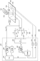
- FIG. 2 is a circuit diagram showing a configuration of a wireless power transmission apparatus (hereinafter simply referred to as a power transmission apparatus) 200 according to the embodiment.
- the power transmission device 200 is used in the power supply system 100 of FIG. 1 and supplies the power signal S2 to the power reception device 300 built in the electronic device 320.
- the power transmission device 200 includes a transmission antenna 201, a driver 204, a control circuit 220, an interface base 240, a first temperature sensor 242, and a second temperature sensor 244.
- the transmission antenna 201 includes a transmission coil (primary coil) 202 and a resonance capacitor 203 connected in series, and has a predetermined resonance frequency fr.
- the driver 204 is an H-bridge circuit including transistors M1 to M4, and applies a pulsed drive signal S1 having a frequency near the resonance frequency fr between both ends of the transmission antenna 201.
- the driver 204 may be a half bridge circuit.
- an electronic device 320 on which the wireless power receiving apparatus 300 is mounted is placed.
- the first temperature sensor 242 measures the temperature T1 of the transmission coil 202 and generates a first temperature signal S11.
- the second temperature sensor 244 measures the temperature T2 of the interface table 240 and generates a second temperature signal S12.
- the kind of temperature sensor is not specifically limited, A thermocouple element, a thermistor, etc. can be utilized.
- the control circuit 220 is a function IC (Integrated Circuit) integrated on a single semiconductor substrate and controls the driver 204.
- the control circuit 220 includes a pulse signal generation unit 222, a pre-driver 224, a demodulator 226, a transmission power measurement unit 228, a foreign object detection unit 230, an A / D converter 232, an A / D converter 234, a subtractor 236, and a determination unit 238. Prepare.
- the demodulator 226 demodulates the control signal S3 included in the coil current I COIL flowing through the transmission coil 202 or the coil voltage V COIL between both ends thereof.
- the control signal S3 includes power control data S5 instructing transmission power, received power data S7 indicating the amount of power currently received by the power receiving apparatus 300, data indicating unique information of the power receiving apparatus 300, and the like.
- the received power amount data S ⁇ b> 7 is input to the foreign object detection unit 230.
- the pulse signal generator 222 generates a pulse signal S6 that instructs the transistors M1 to M4 to be turned on / off based on the power control data S5.
- the pre-driver 224 switches the transistors M1 to M4 of the driver 204 based on the pulse signal S6.
- the transmission power is adjusted based on the frequency of the drive signal S1 applied to the transmission coil 202 by the driver 204, that is, the frequency of the pulse signal S6. Specifically, when the frequency of the pulse signal S6 is brought close to the resonance frequency of the antenna including the transmission coil 202, the transmission power increases, and the transmission power decreases as the distance increases. That is, the pulse signal generation unit 222 adjusts the frequency of the pulse signal S6 based on the power control data S5.
- the transmission power measurement unit 228 calculates the transmission power amount transmitted from the transmission antenna 201 to the power receiving apparatus 300, and generates power transmission amount data S8. For example, the transmission power measuring unit 228 generates the transmission amount data S8 based on the product of the coil current I COIL and the coil voltage V COIL .
- the foreign object detection unit 230 determines the presence / absence of a foreign object based on the relationship between the received power amount data S7 and the transmitted power amount data S8, and asserts a foreign object detection signal S9 (for example, high level) when a foreign object is detected. This is called the FOD function.
- the A / D converter 232 and the A / D converter 234 respectively convert the first temperature signal S11 and the second temperature signal S12 into digital values. Based on the first temperature T1 indicated by the first temperature signal S11, the second temperature T2 indicated by the second temperature signal S12, and the foreign matter detection signal S9, the determination unit 238 detects the presence or absence of foreign matter and the positional deviation of the electronic device 320. .
- the determination unit 238 compares the temperature difference ⁇ T with the first threshold value T TH1, and when the temperature difference ⁇ T is larger, the pulse signal generation unit 222 (and / or the pre-driver 224) stops or reduces the power signal S2. ) To limit power transmission.
- the determination unit 238 causes the pulse signal generation unit 222 (and / or the predriver 224) to stop or decrease the power signal S2. To limit power transmission.
- the difference ⁇ T is smaller than the second threshold value TTH2 , the original power is maintained or the power is slightly reduced. Effectively continue power transmission.
- the determination unit 238 has a thermal shutdown function.
- the foreign object detection unit 230 outputs the power signal S2 regardless of whether there is a foreign object or whether there is a displacement.
- the pulse signal generator 222 (and / or the pre-driver 224) is instructed to stop or decrease, and power transmission is limited.
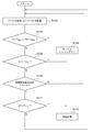
- FIG. 3 is a flowchart of power control based on foreign object / position shift detection of the power transmission device 200 of FIG.
- the determination unit 238 performs a thermal shutdown of the power transmission device 200 and stops power transmission (S104).
- FIGS. 4A to 4C are diagrams showing the positional relationship between the interface table 240 and the electronic device 320.
- FIG. FIG. 4A shows a state in which the electronic device 320 is correctly arranged on the interface table 240.
- the difference ⁇ T between the temperature T1 of the transmission coil 202 and the temperature T2 of the interface base 240 is small, and the foreign object detection signal S9 is not asserted. Therefore, electronic device 320 is charged by normal feedback control.
- a conductive foreign object 400 is placed on the interface table 240 in addition to the electronic device 320.
- the foreign object 400 and the transmission coil 202 are coupled, current flows through the foreign object 400 by electromagnetic induction, and the foreign object 400 generates heat.
- the sum of the power consumed by the foreign object 400 and the power received by the electronic device 320 is the transmission power of the power transmission device 200. Therefore, the error between the power reception amount data S7 and the power transmission amount data S8 acquired in the power transmission device 200 increases, and the foreign object detection signal S9 is asserted. Further, the heat generated by the foreign object 400 is conducted to the interface table 240, the temperature T2 of the interface table 240 rises, and the temperature difference ⁇ T eventually exceeds the threshold value TTH2, thereby restricting power transmission.
- the foreign object 400 does not exist on the interface table 240, but the electronic device 320 is displaced with respect to the transmission coil 202.
- the coupling coefficient between the transmission coil 202 and the reception coil 302 is smaller than the value expected in the state of FIG. 4A, the received power amount data S7 acquired in the power transmission device 200 and the actual electronic device The error in the amount of power received by 320 increases.
- the foreign substance detection signal S9 is asserted by the determination unit 238.
- the temperature difference ⁇ T is smaller than the second threshold value TTH2 , power transmission is not limited and is continued.
- each error of the received power amount data S7 or the transmitted power amount data S8 increases. Thereby, even in the state of FIG. 4A, the foreign object may be erroneously detected by the FOD function, and the foreign object detection signal S9 may be asserted. However, the temperature difference ⁇ T in this case because the smaller than the second threshold T TH2, it is possible to continue normal power transmission.
- the positional deviation can be detected by detecting the temperature difference ⁇ T between the interface table 240 and the transmission coil 202.
- positional deviation and foreign object detection can be distinguished by comparing temperature difference ⁇ T and second threshold value TTH2 .
- the power transmission device 200 and the power reception device 300 are used. Can be protected.
- threshold values T TH1 , T TH2 , T SD1 , and T SD2 can be set independently, so that each state can be appropriately determined.
- the determination unit 238 may be configured by an analog circuit, more specifically, a combination of an analog subtractor and a voltage comparator.
- the wireless power transmission device conforming to the Qi standard has been described.
- the present invention is not limited to this, and the wireless power transmission device used in a system similar to the Qi standard or a standard that will be developed in the future.
- the present invention can also be applied to a compliant power transmission device 200.
- DESCRIPTION OF SYMBOLS 100 Power feeding system, 200, TX ... Power transmission apparatus, 201 ... Transmitting antenna, 202 ... Transmitting coil, 203 ... Resonance capacitor, 204 ... Driver, 206 ... Controller, 208 ... Demodulator, 300, RX ... Power receiving apparatus, 302 ... Reception Coil, 304 ... Rectifier circuit, 306 ... Capacitor, 308 ... Modulator, 310 ... Load circuit, 312 ... Controller, 314 ... Power supply circuit, 320 ... Electronic equipment, 220 ... Control circuit, 222 ... Pulse signal generator, 224 ...
- Pre Driver 226 Demodulator 228 Transmission power measurement unit 230
- Foreign object detection unit 232 234
- Subtractor 238 Determination unit 240
- Interface unit 242 First temperature sensor 244 ... second temperature sensor, S1 ... drive signal, S2 ... power signal, S3 ... control signal, S5 ... power Your data, S6 ... pulse signals, S7 ... received power amount data, S8 ... power amount data, S9 ... foreign matter detection signal, S11 ... first temperature signal, S12 ... second temperature signal.
- the present invention can be used for wireless power feeding.
Landscapes
- Engineering & Computer Science (AREA)
- Power Engineering (AREA)
- Computer Networks & Wireless Communication (AREA)
- Charge And Discharge Circuits For Batteries Or The Like (AREA)
Abstract
Description
「送電を制限する」とは、送信電力をゼロとすること、あるいは送信電力を減少させること、などを含む。
つまり、FOD機能により異物が判定された場合であっても、送信コイルとインタフェース台の温度差が小さい場合には位置ずれに起因する誤判定である可能性が高い。そこで、温度差と第2しきい値を比較することにより、位置ずれと異物検出を区別することができる。
これにより、その原因にかかわらず、送電装置200が過熱状態となった場合には、送電装置200および受電装置300を保護することができる。
同様に、「部材Cが、部材Aと部材Bの間に設けられた状態」とは、部材Aと部材C、あるいは部材Bと部材Cが直接的に接続される場合のほか、それらの電気的な接続状態に実質的な影響を及ぼさない、あるいはそれらの結合により奏される機能や効果を損なわせない、その他の部材を介して間接的に接続される場合も含む。
図3は、図2の送電装置200の異物・位置ずれ検出にもとづく電力制御のフローチャートである。
異物検出信号S9がアサートされている場合(S108のY)、ΔTとTTH2が比較される(S112)。そして、ΔT>TTH2のとき(S112のY)、インタフェース台240上に異物が存在する可能性が高いため、送電を制限する(S110)。異物検出信号S9がアサートされた場合であっても、ΔT<TTH2が成り立つ場合(S112のN)、異物は存在しておらず、コイルの位置ずれの可能性が高いため、ステップS100に戻り、監視を継続する。
Claims (8)
- 送信コイルを含み、電力信号を送信する送信アンテナと、
前記送信アンテナに駆動信号を印加するドライバと、
前記送信コイルの温度を測定し、第1温度信号を生成する第1温度センサと、
ワイヤレス受電装置を搭載する電子機器が載せられるインタフェース台の温度を測定し、第2温度信号を生成する第2温度センサと、
前記ドライバを制御する制御回路であって、前記第1温度信号と前記第2温度信号の差分に応じて前記電力信号を制御する制御回路と、
を備えることを特徴とするワイヤレス送電装置。 - 前記制御回路は、前記差分が第1しきい値より大きいとき、送電を制限することを特徴とする請求項1に記載のワイヤレス送電装置。
- 前記制御回路は、前記インタフェース台上の異物を検出可能に構成され、前記異物が有ると判定され、かつ前記差分が第2しきい値より大きいとき、送電を制限し、前記差分が第2しきい値より小さいとき、送電を実質的に継続することを特徴とする請求項2に記載のワイヤレス送電装置。
- 前記制御回路はさらに、前記第1温度信号および前記第2温度信号の少なくとも一方が、サーマルシャットダウン用のしきい値より大きいとき、送電を制限することを特徴とする請求項1から3のいずれかに記載のワイヤレス送電装置。
- ワイヤレス送電装置の制御方法であって、
ドライバが、パルス信号にもとづいて送信コイルを含む送信アンテナに駆動信号を印加するステップと、
前記送信アンテナが、前記パルス信号に応じて電力信号を送信するステップと、
前記送信コイルの温度を測定し、第1温度信号を生成するステップと、
ワイヤレス受電装置を搭載する電子機器が載せられるインタフェース台の温度を測定し、第2温度信号を生成するステップと、
前記第1温度信号と前記第2温度信号の差分を検出するステップと、
前記差分に応じて前記ドライバを制御するステップと、
を備えることを特徴とする方法。 - 前記ドライバを制御するステップは、
前記差分を第1しきい値と比較するステップと、
前記差分が前記第1しきい値より大きいとき、送電を制限するステップと、
を含むことを特徴とする請求項5に記載の方法。 - 前記ドライバを制御するステップは、
異物を検出するステップと、
前記異物が有ると判定され、かつ前記差分が第2しきい値より大きいとき送電を制限し、前記差分が第2しきい値より小さいとき、送電を実質的に継続するステップと、
を含むことを特徴とする請求項6に記載の方法。 - 前記ドライバを制御するステップは、
前記第1温度信号および前記第2温度信号の少なくとも一方をサーマルシャットダウン用の第3しきい値と比較するステップと、
前記第1温度信号および前記第2温度信号の少なくとも一方が前記第3しきい値より大きいとき、送電を制限するステップと、
を含むことを特徴とする請求項5から7のいずれかに記載の方法。
Priority Applications (3)
| Application Number | Priority Date | Filing Date | Title |
|---|---|---|---|
| KR1020167001743A KR102081477B1 (ko) | 2013-06-25 | 2014-05-26 | 와이어리스 송전 장치 및 그 제어 방법 |
| CN201480036098.4A CN105324914B (zh) | 2013-06-25 | 2014-05-26 | 无线供电装置及其控制方法 |
| US14/980,760 US9929604B2 (en) | 2013-06-25 | 2015-12-28 | Apparatus and method for wireless power transmission |
Applications Claiming Priority (2)
| Application Number | Priority Date | Filing Date | Title |
|---|---|---|---|
| JP2013-133088 | 2013-06-25 | ||
| JP2013133088A JP6147112B2 (ja) | 2013-06-25 | 2013-06-25 | ワイヤレス送電装置およびその制御方法 |
Related Child Applications (1)
| Application Number | Title | Priority Date | Filing Date |
|---|---|---|---|
| US14/980,760 Continuation US9929604B2 (en) | 2013-06-25 | 2015-12-28 | Apparatus and method for wireless power transmission |
Publications (1)
| Publication Number | Publication Date |
|---|---|
| WO2014207995A1 true WO2014207995A1 (ja) | 2014-12-31 |
Family
ID=52141371
Family Applications (1)
| Application Number | Title | Priority Date | Filing Date |
|---|---|---|---|
| PCT/JP2014/002759 Ceased WO2014207995A1 (ja) | 2013-06-25 | 2014-05-26 | ワイヤレス送電装置およびその制御方法 |
Country Status (6)
| Country | Link |
|---|---|
| US (1) | US9929604B2 (ja) |
| JP (1) | JP6147112B2 (ja) |
| KR (1) | KR102081477B1 (ja) |
| CN (1) | CN105324914B (ja) |
| TW (1) | TWI626809B (ja) |
| WO (1) | WO2014207995A1 (ja) |
Cited By (3)
| Publication number | Priority date | Publication date | Assignee | Title |
|---|---|---|---|---|
| EP3128645A1 (en) * | 2015-08-06 | 2017-02-08 | Panasonic Intellectual Property Management Co., Ltd. | Wireless power transmitting device and wireless power transmission system |
| JP2017118690A (ja) * | 2015-12-24 | 2017-06-29 | トヨタ自動車株式会社 | 非接触送電装置及び電力伝送システム |
| EP3282554A4 (en) * | 2015-04-07 | 2018-03-21 | Nissan Motor Co., Ltd. | Temperature estimation device and temperature estimation method for contactless power-reception device |
Families Citing this family (22)
| Publication number | Priority date | Publication date | Assignee | Title |
|---|---|---|---|---|
| GB2540610B (en) * | 2015-07-23 | 2017-12-06 | Advanced Risc Mach Ltd | Gathering monitoring data relating to the operation of a data processing system |
| CN106560979B (zh) * | 2015-10-02 | 2021-03-30 | 松下知识产权经营株式会社 | 无线电力传输系统 |
| JP6679343B2 (ja) * | 2016-02-24 | 2020-04-15 | ローム株式会社 | ワイヤレス送電装置および送電制御回路、充電器 |
| JP2017208941A (ja) * | 2016-05-18 | 2017-11-24 | ローム株式会社 | ワイヤレス送電装置、その制御回路、充電器、異常検出方法 |
| KR101916730B1 (ko) * | 2016-08-19 | 2019-01-30 | 엘지전자 주식회사 | 무선전력 전송장치 |
| WO2018034405A1 (ko) * | 2016-08-19 | 2018-02-22 | 엘지전자 주식회사 | 무선전력 전송장치 |
| KR102561570B1 (ko) * | 2016-10-06 | 2023-07-31 | 삼성전자주식회사 | 무선 충전을 제어하는 전자 장치 및 방법 |
| JP6925873B2 (ja) | 2017-06-01 | 2021-08-25 | 東芝テック株式会社 | 非接触受電装置及び非接触受電方法 |
| DE102017210835A1 (de) * | 2017-06-27 | 2018-12-27 | Laird Dabendorf Gmbh | Verfahren zur Detektion eines Fremdobjekts und Vorrichtung zur induktiven Energieübertragung an ein portables Endgerät |
| DE112017007722B4 (de) | 2017-08-01 | 2026-02-19 | Ford Global Technologies, Llc | Aktivierung einer drahtlosen ladevorrichtung |
| CN107801237A (zh) * | 2017-11-15 | 2018-03-13 | 北京联盛德微电子有限责任公司 | 具备功率控制装置的无线充电系统及功率控制方法 |
| US20190181693A1 (en) * | 2017-12-08 | 2019-06-13 | Toshiba Tec Kabushiki Kaisha | Non-contact power receiving device and non-contact power transmitting device |
| JP2019106850A (ja) * | 2017-12-08 | 2019-06-27 | 東芝テック株式会社 | 非接触受電装置及び非接触送電装置 |
| US11240942B2 (en) * | 2018-06-20 | 2022-02-01 | Integrated Device Technology, Inc. | Control of ionic cooling in wireless charging systems |
| US10505403B1 (en) | 2018-08-31 | 2019-12-10 | Apple Inc. | Wireless charging system with temperature sensing |
| US10658878B2 (en) * | 2018-08-31 | 2020-05-19 | Apple Inc. | Wireless charging system with temperature sensor array |
| JP7119838B2 (ja) * | 2018-09-26 | 2022-08-17 | トヨタ自動車株式会社 | 非接触送電装置 |
| JP7036222B2 (ja) * | 2018-10-05 | 2022-03-15 | 株式会社Ihi | 位置ずれ検出装置およびコイル装置 |
| JP7457493B2 (ja) * | 2019-12-10 | 2024-03-28 | キヤノン株式会社 | 送電装置、受電装置、それらの制御方法およびプログラム |
| CN112003346B (zh) * | 2020-08-18 | 2022-06-10 | Oppo广东移动通信有限公司 | 充电方法和电子设备 |
| US12562600B2 (en) * | 2021-07-20 | 2026-02-24 | Spark Connected LLC | Foreign object detection testing for wireless chargers |
| CN113858982B (zh) * | 2021-09-14 | 2024-04-05 | 合肥有感科技有限责任公司 | 无线充电异物检测方法 |
Citations (3)
| Publication number | Priority date | Publication date | Assignee | Title |
|---|---|---|---|---|
| JP2009022126A (ja) * | 2007-07-13 | 2009-01-29 | Seiko Epson Corp | 送電装置及び電子機器 |
| WO2011132471A1 (ja) * | 2010-04-19 | 2011-10-27 | パナソニック電工 株式会社 | 非接触送電装置、非接触受電装置及び非接触充電システム |
| JP2013005682A (ja) * | 2011-06-21 | 2013-01-07 | Panasonic Corp | 非接触電力伝送システム |
Family Cites Families (7)
| Publication number | Priority date | Publication date | Assignee | Title |
|---|---|---|---|---|
| JP5494220B2 (ja) * | 2010-05-19 | 2014-05-14 | 株式会社オートネットワーク技術研究所 | 無線給電システム |
| US9035626B2 (en) * | 2010-08-18 | 2015-05-19 | Volterra Semiconductor Corporation | Switching circuits for extracting power from an electric power source and associated methods |
| JP5713714B2 (ja) * | 2011-02-10 | 2015-05-07 | キヤノン株式会社 | 給電装置及び制御方法 |
| JP5893285B2 (ja) | 2011-08-04 | 2016-03-23 | キヤノン株式会社 | 給電装置及びプログラム |
| JP2013059236A (ja) * | 2011-09-09 | 2013-03-28 | Sony Corp | 検知装置、受電装置、送電装置、非接触電力伝送システム及び検知方法 |
| TWM447036U (zh) * | 2012-07-20 | 2013-02-11 | ming-xiang Ye | 攜帶式電子產品的雙向無線充放電裝置 |
| EP3051410A1 (en) * | 2015-02-02 | 2016-08-03 | Nokia Technologies OY | An apparatus and associated methods for provision of wireless power |
-
2013
- 2013-06-25 JP JP2013133088A patent/JP6147112B2/ja active Active
-
2014
- 2014-05-26 WO PCT/JP2014/002759 patent/WO2014207995A1/ja not_active Ceased
- 2014-05-26 KR KR1020167001743A patent/KR102081477B1/ko active Active
- 2014-05-26 CN CN201480036098.4A patent/CN105324914B/zh active Active
- 2014-06-12 TW TW103120369A patent/TWI626809B/zh active
-
2015
- 2015-12-28 US US14/980,760 patent/US9929604B2/en active Active
Patent Citations (3)
| Publication number | Priority date | Publication date | Assignee | Title |
|---|---|---|---|---|
| JP2009022126A (ja) * | 2007-07-13 | 2009-01-29 | Seiko Epson Corp | 送電装置及び電子機器 |
| WO2011132471A1 (ja) * | 2010-04-19 | 2011-10-27 | パナソニック電工 株式会社 | 非接触送電装置、非接触受電装置及び非接触充電システム |
| JP2013005682A (ja) * | 2011-06-21 | 2013-01-07 | Panasonic Corp | 非接触電力伝送システム |
Cited By (3)
| Publication number | Priority date | Publication date | Assignee | Title |
|---|---|---|---|---|
| EP3282554A4 (en) * | 2015-04-07 | 2018-03-21 | Nissan Motor Co., Ltd. | Temperature estimation device and temperature estimation method for contactless power-reception device |
| EP3128645A1 (en) * | 2015-08-06 | 2017-02-08 | Panasonic Intellectual Property Management Co., Ltd. | Wireless power transmitting device and wireless power transmission system |
| JP2017118690A (ja) * | 2015-12-24 | 2017-06-29 | トヨタ自動車株式会社 | 非接触送電装置及び電力伝送システム |
Also Published As
| Publication number | Publication date |
|---|---|
| CN105324914A (zh) | 2016-02-10 |
| JP2015008605A (ja) | 2015-01-15 |
| US20160134129A1 (en) | 2016-05-12 |
| TWI626809B (zh) | 2018-06-11 |
| US9929604B2 (en) | 2018-03-27 |
| CN105324914B (zh) | 2019-08-13 |
| TW201501444A (zh) | 2015-01-01 |
| JP6147112B2 (ja) | 2017-06-14 |
| KR20160022899A (ko) | 2016-03-02 |
| KR102081477B1 (ko) | 2020-02-25 |
Similar Documents
| Publication | Publication Date | Title |
|---|---|---|
| JP6147112B2 (ja) | ワイヤレス送電装置およびその制御方法 | |
| KR102089832B1 (ko) | 와이어리스 수전 장치 및 그 제어 회로, 그것을 사용한 전자 기기, 이상 검출 방법 | |
| JP6632299B2 (ja) | ワイヤレス送電装置、その制御回路、充電器、およびパワーロスメソッドによる異物検出のキャリブレーション方法 | |
| JP6677795B2 (ja) | ワイヤレス送電装置、その制御方法、送電制御回路、充電器 | |
| JP6410641B2 (ja) | ワイヤレス送電装置、異物検出方法、充電器 | |
| CN108604834B (zh) | 用于无线功率系统中的功率损耗校准的方法和装置 | |
| CN103988269B (zh) | 用于非接触式感应能量传递的插接装置以及用于这种插接装置的运行方法 | |
| JP2022046747A (ja) | ワイヤレス電力伝送システムを保護するためのシステムおよび方法 | |
| US11495962B2 (en) | Electronic device wirelessly receiving power and method of operating same | |
| US20170179765A1 (en) | Contactless Connector and Contactless Connector System | |
| JP2017208941A (ja) | ワイヤレス送電装置、その制御回路、充電器、異常検出方法 | |
| JP6725992B2 (ja) | ワイヤレス送電装置およびその制御ic、異常検出方法、充電器 | |
| JP6679343B2 (ja) | ワイヤレス送電装置および送電制御回路、充電器 | |
| JP2013252028A (ja) | 無接点給電装置 |
Legal Events
| Date | Code | Title | Description |
|---|---|---|---|
| WWE | Wipo information: entry into national phase |
Ref document number: 201480036098.4 Country of ref document: CN |
|
| 121 | Ep: the epo has been informed by wipo that ep was designated in this application |
Ref document number: 14818314 Country of ref document: EP Kind code of ref document: A1 |
|
| NENP | Non-entry into the national phase |
Ref country code: DE |
|
| ENP | Entry into the national phase |
Ref document number: 20167001743 Country of ref document: KR Kind code of ref document: A |
|
| 122 | Ep: pct application non-entry in european phase |
Ref document number: 14818314 Country of ref document: EP Kind code of ref document: A1 |