WO2014199825A1 - 水分含有ガスの不純物除去装置及び不純物除去システム - Google Patents
水分含有ガスの不純物除去装置及び不純物除去システム Download PDFInfo
- Publication number
- WO2014199825A1 WO2014199825A1 PCT/JP2014/064068 JP2014064068W WO2014199825A1 WO 2014199825 A1 WO2014199825 A1 WO 2014199825A1 JP 2014064068 W JP2014064068 W JP 2014064068W WO 2014199825 A1 WO2014199825 A1 WO 2014199825A1
- Authority
- WO
- WIPO (PCT)
- Prior art keywords
- drain
- gas
- cooling
- cooling space
- outlet
- Prior art date
- Legal status (The legal status is an assumption and is not a legal conclusion. Google has not performed a legal analysis and makes no representation as to the accuracy of the status listed.)
- Ceased
Links
Images


Classifications
-
- B—PERFORMING OPERATIONS; TRANSPORTING
- B01—PHYSICAL OR CHEMICAL PROCESSES OR APPARATUS IN GENERAL
- B01D—SEPARATION
- B01D53/00—Separation of gases or vapours; Recovering vapours of volatile solvents from gases; Chemical or biological purification of waste gases, e.g. engine exhaust gases, smoke, fumes, flue gases, aerosols
- B01D53/34—Chemical or biological purification of waste gases
- B01D53/74—General processes for purification of waste gases; Apparatus or devices specially adapted therefor
- B01D53/77—Liquid phase processes
- B01D53/79—Injecting reactants
-
- B—PERFORMING OPERATIONS; TRANSPORTING
- B01—PHYSICAL OR CHEMICAL PROCESSES OR APPARATUS IN GENERAL
- B01D—SEPARATION
- B01D5/00—Condensation of vapours; Recovering volatile solvents by condensation
- B01D5/0003—Condensation of vapours; Recovering volatile solvents by condensation by using heat-exchange surfaces for indirect contact between gases or vapours and the cooling medium
- B01D5/0009—Horizontal tubes
-
- B—PERFORMING OPERATIONS; TRANSPORTING
- B01—PHYSICAL OR CHEMICAL PROCESSES OR APPARATUS IN GENERAL
- B01D—SEPARATION
- B01D53/00—Separation of gases or vapours; Recovering vapours of volatile solvents from gases; Chemical or biological purification of waste gases, e.g. engine exhaust gases, smoke, fumes, flue gases, aerosols
- B01D53/002—Separation of gases or vapours; Recovering vapours of volatile solvents from gases; Chemical or biological purification of waste gases, e.g. engine exhaust gases, smoke, fumes, flue gases, aerosols by condensation
-
- B—PERFORMING OPERATIONS; TRANSPORTING
- B01—PHYSICAL OR CHEMICAL PROCESSES OR APPARATUS IN GENERAL
- B01D—SEPARATION
- B01D53/00—Separation of gases or vapours; Recovering vapours of volatile solvents from gases; Chemical or biological purification of waste gases, e.g. engine exhaust gases, smoke, fumes, flue gases, aerosols
- B01D53/34—Chemical or biological purification of waste gases
- B01D53/46—Removing components of defined structure
- B01D53/48—Sulfur compounds
- B01D53/50—Sulfur oxides
- B01D53/501—Sulfur oxides by treating the gases with a solution or a suspension of an alkali or earth-alkali or ammonium compound
- B01D53/504—Sulfur oxides by treating the gases with a solution or a suspension of an alkali or earth-alkali or ammonium compound characterised by a specific device
-
- B—PERFORMING OPERATIONS; TRANSPORTING
- B01—PHYSICAL OR CHEMICAL PROCESSES OR APPARATUS IN GENERAL
- B01D—SEPARATION
- B01D53/00—Separation of gases or vapours; Recovering vapours of volatile solvents from gases; Chemical or biological purification of waste gases, e.g. engine exhaust gases, smoke, fumes, flue gases, aerosols
- B01D53/34—Chemical or biological purification of waste gases
- B01D53/46—Removing components of defined structure
- B01D53/60—Simultaneously removing sulfur oxides and nitrogen oxides
-
- B—PERFORMING OPERATIONS; TRANSPORTING
- B01—PHYSICAL OR CHEMICAL PROCESSES OR APPARATUS IN GENERAL
- B01D—SEPARATION
- B01D53/00—Separation of gases or vapours; Recovering vapours of volatile solvents from gases; Chemical or biological purification of waste gases, e.g. engine exhaust gases, smoke, fumes, flue gases, aerosols
- B01D53/34—Chemical or biological purification of waste gases
- B01D53/46—Removing components of defined structure
- B01D53/68—Halogens or halogen compounds
-
- B—PERFORMING OPERATIONS; TRANSPORTING
- B01—PHYSICAL OR CHEMICAL PROCESSES OR APPARATUS IN GENERAL
- B01D—SEPARATION
- B01D2251/00—Reactants
- B01D2251/30—Alkali metal compounds
- B01D2251/304—Alkali metal compounds of sodium
-
- B—PERFORMING OPERATIONS; TRANSPORTING
- B01—PHYSICAL OR CHEMICAL PROCESSES OR APPARATUS IN GENERAL
- B01D—SEPARATION
- B01D2251/00—Reactants
- B01D2251/40—Alkaline earth metal or magnesium compounds
-
- B—PERFORMING OPERATIONS; TRANSPORTING
- B01—PHYSICAL OR CHEMICAL PROCESSES OR APPARATUS IN GENERAL
- B01D—SEPARATION
- B01D2251/00—Reactants
- B01D2251/40—Alkaline earth metal or magnesium compounds
- B01D2251/404—Alkaline earth metal or magnesium compounds of calcium
-
- B—PERFORMING OPERATIONS; TRANSPORTING
- B01—PHYSICAL OR CHEMICAL PROCESSES OR APPARATUS IN GENERAL
- B01D—SEPARATION
- B01D2256/00—Main component in the product gas stream after treatment
- B01D2256/22—Carbon dioxide
-
- B—PERFORMING OPERATIONS; TRANSPORTING
- B01—PHYSICAL OR CHEMICAL PROCESSES OR APPARATUS IN GENERAL
- B01D—SEPARATION
- B01D2257/00—Components to be removed
- B01D2257/20—Halogens or halogen compounds
- B01D2257/204—Inorganic halogen compounds
- B01D2257/2045—Hydrochloric acid
-
- B—PERFORMING OPERATIONS; TRANSPORTING
- B01—PHYSICAL OR CHEMICAL PROCESSES OR APPARATUS IN GENERAL
- B01D—SEPARATION
- B01D2257/00—Components to be removed
- B01D2257/30—Sulfur compounds
- B01D2257/302—Sulfur oxides
-
- B—PERFORMING OPERATIONS; TRANSPORTING
- B01—PHYSICAL OR CHEMICAL PROCESSES OR APPARATUS IN GENERAL
- B01D—SEPARATION
- B01D2257/00—Components to be removed
- B01D2257/40—Nitrogen compounds
- B01D2257/404—Nitrogen oxides other than dinitrogen oxide
-
- B—PERFORMING OPERATIONS; TRANSPORTING
- B01—PHYSICAL OR CHEMICAL PROCESSES OR APPARATUS IN GENERAL
- B01D—SEPARATION
- B01D2257/00—Components to be removed
- B01D2257/60—Heavy metals or heavy metal compounds
- B01D2257/602—Mercury or mercury compounds
-
- B—PERFORMING OPERATIONS; TRANSPORTING
- B01—PHYSICAL OR CHEMICAL PROCESSES OR APPARATUS IN GENERAL
- B01D—SEPARATION
- B01D2258/00—Sources of waste gases
- B01D2258/02—Other waste gases
- B01D2258/0283—Flue gases
-
- Y—GENERAL TAGGING OF NEW TECHNOLOGICAL DEVELOPMENTS; GENERAL TAGGING OF CROSS-SECTIONAL TECHNOLOGIES SPANNING OVER SEVERAL SECTIONS OF THE IPC; TECHNICAL SUBJECTS COVERED BY FORMER USPC CROSS-REFERENCE ART COLLECTIONS [XRACs] AND DIGESTS
- Y02—TECHNOLOGIES OR APPLICATIONS FOR MITIGATION OR ADAPTATION AGAINST CLIMATE CHANGE
- Y02E—REDUCTION OF GREENHOUSE GAS [GHG] EMISSIONS, RELATED TO ENERGY GENERATION, TRANSMISSION OR DISTRIBUTION
- Y02E20/00—Combustion technologies with mitigation potential
- Y02E20/34—Indirect CO2mitigation, i.e. by acting on non CO2directly related matters of the process, e.g. pre-heating or heat recovery
Definitions
- the present invention relates to an impurity removal apparatus and an impurity removal system for a moisture-containing gas that are configured to remove impurities contained in the moisture-containing gas.
- the gas discharged from the combustion device, the reaction device, or the like contains impurities that must be removed.
- an oxyfuel combustion apparatus has been studied, and a coal fired boiler that oxyfuels pulverized coal Is attracting attention.
- This coal fired boiler uses oxygen instead of air as an oxidant to produce exhaust gas mainly composed of carbon dioxide (CO 2 ), which is liquefied by compressing and cooling the exhaust gas with high carbon dioxide concentration.
- Carbon dioxide is used, and the liquefied carbon dioxide is transported to the destination by a transportation means such as a ship or a vehicle and stored in the ground, or the pressure of liquefied carbon dioxide is increased and transported to the destination by a pipeline. Storage in is being considered.
- Impurities such as hydrogen chloride (HCl) and dust.
- Such impurities need to be removed from environmental pollution problems or problems such as the occurrence of corrosion, and contamination of impurities is also removed because it lowers the purity of the carbon dioxide (CO 2 ) extracted. There is a need.
- sulfur oxide (SO x ) is dissolved in water by contact with water to become sulfuric acid (H 2 SO 4 ), and hydrogen chloride (HCl) is dissolved in water to become hydrochloric acid.
- SO x sulfur oxide
- HCl hydrogen chloride
- Such water-soluble sulfur oxides, hydrogen chloride, and dust can be separated by contacting with water by water spray or the like.
- nitrogen dioxide (NO 2 ) can be separated by being dissolved in water to be nitric acid (HNO 3 ) by contacting with water.
- HNO 3 nitric acid
- O 2 oxygen
- most of the nitrogen (N 2 ) exists as nitric oxide (NO), and this nitric oxide (NO) is water. Since it is insoluble in water, it cannot be removed by water spraying.
- sulfuric acid is known to corrode equipment of exhaust gas treatment equipment, and mercury as the trace metal can damage the low-temperature aluminum member of the heat exchanger. I know it. Therefore, it is preferable to remove these impurities at an early stage.
- the impurities are mixed into the exhaust gas, the purity of carbon dioxide is lowered, so that it is difficult to compress and cool and liquefy, and there is a problem that the equipment for liquefaction becomes large. Accordingly, it is very important to remove impurities in the exhaust gas in a system that generates exhaust gas mainly composed of carbon dioxide and disposes of the carbon dioxide, such as a coal fired boiler that performs oxyfuel combustion.
- coal fired boilers that perform oxyfuel combustion especially for sulfur oxides, where corrosion is a problem, it is said to be wet, consisting of the spray tower system or packed tower system used in conventional air fired boilers, etc. Removal is performed by providing a desulfurization apparatus. Also, since nitrogen and nitrogen oxides derived from coal raw materials are generated in the exhaust gas from coal fired boilers that perform oxyfuel combustion, a denitration device such as a catalyst system is provided upstream of the desulfurization device to oxidize nitrogen and nitrogen. Things are being removed.
- a dust collector and a wet desulfurization device are provided in a duct that guides exhaust gas from a boiler that burns fuel with a combustion gas in which oxygen-rich gas and circulating exhaust gas are mixed, and downstream of the dust collector.
- Process of compressing the exhaust gas of the CO 2 separation means comprising: an exhaust gas recirculation duct for leading a part of the exhaust gas on the side to the boiler; and a CO 2 separation means for compressing the exhaust gas downstream of the desulfurization device to separate carbon dioxide
- an exhaust gas treatment system in which the water separated in step (b) is supplied to an absorbent that is circulated and used in a desulfurization apparatus (see Patent Document 1).
- Patent Document 2 discloses a compressor that compresses exhaust gas from an oxygen combustion device and makes impurities in the exhaust gas water-soluble, and cools the exhaust gas compressed by the compressor to condense moisture to dissolve impurities.
- a front impurity removing device comprising a cooler for removing drain, a rear compressor for compressing exhaust gas at a pressure higher than that of the compressor, and at least one rear impurity removing device for removing drain with a rear cooler.
- An exhaust gas treatment system for an oxyfuel combustion apparatus is disclosed.
- Patent Document 3 when a compressor for raising the pressure of the gaseous carbon dioxide, molecular oxygen and, SO 2 is removed, in the presence of NOx, the SO 2 to sulfuric acid, and / Or at least one counter-flow gas-liquid contact device for washing the gaseous carbon dioxide with water at an elevated pressure for a sufficient time to convert NOx to nitric acid, and gaseous carbon dioxide at the elevated pressure.
- a carbon dioxide purification apparatus comprising conduit means for supplying gas and liquid contact devices from the compressor to each of the gas and liquid contact devices, and conduit means for recirculating sulfuric acid aqueous solution and / or nitric acid aqueous solution to each of the gas and liquid contact devices.
- Patent Document 4 boiler exhaust gas containing ash is cooled to 40 ° C. or less using boiler feed water or boiler combustion air, desulfurization absorption tower outlet exhaust gas, or one or more of seawater, Condensate the water inside, remove SOx in the exhaust gas with desulfurization absorption liquid mixed with lime in the ash and condensed water slurry, and separate unnecessary ash by the unnecessary ash sedimentation separator at the bottom of the absorption tower tank A dedusting and desulfurization simultaneous processing apparatus is disclosed. Further, Patent Document 5 discloses that combustion waste gas is brought into gas-liquid countercurrent contact with an aqueous alkali metal carbonate salt solution containing at least 0.1 N alkali metal carbonate using a leaky tower.
- Combustion comprising a step of regenerating an aqueous alkali metal hydroxide solution by reacting the metal salt with an alkaline earth metal hydroxide to separate the generated alkaline earth metal carbonate salt and recovering the aqueous alkali metal hydroxide solution Gas purification system is disclosed.
- JP 2012-143699 A International Publication No. 2012/107953 JP 2007-145709 A Japanese Patent Laid-Open No. 06-126127 JP 2006-263676 A
- the present invention has been made in view of the above-described conventional problems, and provides a moisture-containing gas impurity removal device and an impurity removal system capable of removing impurities contained in a moisture-containing gas with high efficiency by a small device. It is something to be offered.
- the present invention provides a cooler body having a cooling space, a gas inlet communicating with the lower inside of the cooling space, a gas outlet communicating with the upper upper side of the cooling space, and the gas inlet inside the cooling space.
- a cooling pipe disposed between the gas outlets, wherein the cooling fluid from the cooling fluid inlet circulates inside the cooling space and is led out from the cooling fluid outlet; and the gas inlet and the gas outlet inside the cooling space,
- a filler built-in cooler having a filler arranged so as to partition the space vertically;
- a nozzle provided on the inside upper side of the cooling space, and a drain circulation device for supplying and injecting drain from a drain outlet provided in a drain reservoir at an inner bottom portion of the cooling space to the nozzle by a pump;
- the present invention relates to a moisture-containing gas impurity removal device having an alkali agent addition device for adding an alkali agent to the drain.
- a pH detector for detecting the pH of the drain in the drain reservoir, and the addition of the alkaline agent so that the pH detection value detected by the pH detector is maintained at a set value. It is preferred to have an alkaline agent controller that regulates the supply of alkaline agent by the device.
- a level meter for detecting the drain level of the drain reservoir and an adjustment provided at the drain outlet so that the level detection value detected by the level meter is maintained at a set value. It is preferred to have a level controller that regulates the valve.
- the gas inlet is connected to a compressor.
- a refrigerator is provided between the cooling fluid inlet and the cooling fluid outlet.
- the present invention includes a multi-stage impurity separator having a multi-stage compressor and an aftercooler that cools and compresses the gas compressed by each compressor, and includes impurities from the oxyfuel combustion apparatus. Downstream of the impurity removal mechanism configured to remove A cooler body having a cooling space, a gas inlet communicating with the lower inside of the cooling space, a gas outlet communicating with the upper upper side of the cooling space, and between the gas inlet and the gas outlet inside the cooling space And a cooling pipe that circulates the cooling fluid from the cooling fluid inlet to the inside of the cooling space and leads out from the cooling fluid outlet, and vertically between the gas inlet and the gas outlet in the cooling space.
- a filler built-in cooler having a filler arranged so as to partition, A nozzle provided in the upper side of the cooling space, a drain circulating device for supplying a drain from a drain outlet provided in a drain reservoir at an inner bottom of the cooling space to the nozzle by a pump, and the cooling fluid inlet;
- An alkali adjuster supply flow for supplying a drain disposed between a cooling fluid outlet and a drain reservoir of the cooler body as an alkali adjuster to at least an upstream side of an aftercooler of the impurity separator at the foremost stage.
- a moisture-containing gas impurity removal system comprising a channel.
- the moisture-containing gas impurity removal apparatus and impurity removal system of the present invention it is possible to obtain an excellent effect that impurities contained in the moisture-containing gas can be removed with high efficiency by a small-sized apparatus.
- FIG. 1 It is a schematic block diagram which shows one Example of the impurity removal apparatus of the water-containing gas of this invention.
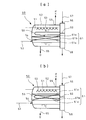
- A is a schematic block diagram which shows the modification of the cooler with a built-in filler of FIG. 1
- (b) is a schematic block diagram which shows another modification of the cooler with a built-in filler of (a).
- FIG. 1 is a schematic configuration diagram showing an embodiment of a moisture-containing gas impurity removing apparatus according to the present invention.
- reference numeral 50 denotes a filler built-in cooler.
- the cooler 50 with a built-in filler includes a cooler body 52 having a cooling space 51, a gas inlet 54 that communicates with the lower interior of the cooling space 51 and introduces a moisture-containing gas 53, and an upper interior of the cooling space 51 And a gas outlet 55 communicating with the gas outlet.
- a cooling fluid 57 such as seawater or other cooling water disposed between the gas inlet 54 and the gas outlet 55 in the cooling space 51 and introduced from the cooling fluid inlet 56 is supplied into the cooling space 51.
- a cooling pipe 59 led out from the cooling fluid outlet 58.
- Reference numeral 60 denotes a partition plate that partitions the cooling fluid inlet 56 and the cooling fluid outlet 58. Further, a filler 61 is provided between the gas inlet 54 and the gas outlet 55 inside the cooling space 51 so as to partition the cooling space 51 vertically.
- the filler 61 has a configuration in which, for example, a granular material 61b (Lashig ring) is filled between the upper and lower perforated plates 61a and 61a.
- a drain reservoir 62 is formed on the inner bottom of the cooling space 51, and a nozzle 63 is provided on the inner upper side of the cooling space 51, and an extraction pipe 65 connected to the drain outlet 64 of the drain reservoir 62.
- a drain circulation device 68 is provided in which the drain D taken out from the nozzle 63 is supplied to the nozzle 63 through a pump 66 and a circulation flow path 67 so as to be ejected from the nozzle 63.
- the circulation channel 67 includes an alkali agent addition device 70 that adds an alkali agent 69 to the drain D flowing in the circulation channel 67.
- the alkali agent 69 include sodium hydroxide (NaOH), ammonia (—NH 3 ), magnesium hydroxide (Mg (OH) 2 ), or a large amount of water (H 2 O) (general water is a weak alkali). Etc. can be used.
- the cooler main body 52 is provided with a level meter 71 for detecting the level of the drain D of the drain reservoir 62 and an extraction pipe 65 so that the level detection value detected by the level meter 71 is held at a set value.
- a level controller 73 for adjusting the control valve 72 is provided.
- the cooler body 52 includes a pH detector 74 for detecting the pH of the drain D of the drain reservoir 62, and the alkali so that the pH detection value detected by the pH detector 74 is maintained at a set value.
- An alkali agent controller 76 that controls the supply valve 75 in the agent addition device 70 to adjust the supply amount of the alkali agent 69 is provided.
- FIG. 2 shows a modification of the embodiment of FIG. 1.
- FIG. 2A shows a cooling pipe 59 disposed above the filler 61 and a nozzle 63 disposed above the cooling pipe 59.
- FIG. 2B shows a case where the cooling pipe 59 is arranged inside the filler 61.
- FIGS. 1 and 2 The operation of the embodiment shown in FIGS. 1 and 2 will be described below.
- a cooling fluid 59 such as seawater or cooling water is supplied to a cooling pipe 59 of a built-in filler cooler 50 constituting the moisture content gas impurity removing device to cool the cooling space 51.
- the drain D in the drain reservoir 62 at the inner bottom is injected from a nozzle 63 provided above the cooling space 51 by a drain circulating device 68.
- the level controller 73 controls the drain D of the drain reservoir 62 detected by the level meter 71 to be kept constant, the drain D of the drain reservoir 62 is drained by the drain circulating device 68. It can be reliably circulated and injected.
- the moisture-containing gas 53 that is taken out from various combustion devices or reaction devices and contains impurities and contains moisture is a cooler main body 52 of a built-in filler cooler 50 that constitutes an impurity removal device for moisture-containing gas.
- the water-containing gas 53 introduced into the cooling space 51 is cooled by heat exchange with the cooling pipe 59, so that the water contained therein is condensed and falls into a drain reservoir 62 as a drain.
- impurities in the gas are removed.
- the drain D is injected into the filler 61 from the nozzle 63 of the drain circulation device 68 and the alkali agent 69 from the alkali agent addition device 70 is further added to the drain D, the filler 61 is added. Impurities are effectively removed by contacting the gas passing through the drain D.
- FIG. 3 shows another embodiment of the apparatus for removing impurities of a water-containing gas according to the present invention.
- the gas inlet 54 is provided with a compressor 77 for compressing the water-containing gas 53.
- the cooling fluid outlet 58 and the cooling fluid inlet 56 are connected by a circulation channel 90, and a refrigerator 78 is provided in the circulation channel 90.
- the low-temperature cooling fluid 57 (cooling medium) from the refrigerator 78 is supplied to the cooling pipe 59 and the water-containing gas 53 is further cooled.
- the drain D is separated, and impurities in the gas are effectively removed by further increasing the penetration into the drain D due to the low temperature.
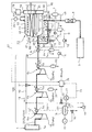
- FIG. 4 is a schematic configuration diagram showing an embodiment of a moisture-containing gas impurity removal system in which the filler built-in cooler according to the present invention is applied to the downstream side of the impurity removal mechanism 100 that removes gas impurities from the oxygen combustion apparatus. is there.
- reference numeral 1 denotes an oxyfuel combustion apparatus composed of a coal fired boiler 1a or the like for burning pulverized coal with oxygen, and the oxyfuel combustion apparatus 1 has an exhaust gas 2 (water-containing gas 53) mainly composed of carbon dioxide (CO 2 ). Is discharged.
- an exhaust gas 2 water-containing gas 53
- CO 2 carbon dioxide
- pressure required for liquefaction in the carbon dioxide liquefier 3 or the An impurity removing mechanism 100 that compresses the exhaust gas 2 to a target pressure that is a predetermined pressure close to the pressure and removes impurities in the exhaust gas 2 is provided.
- the impurity removal mechanism 100 includes a plurality of stages of compressors 4a, 4b, and 4c that compress the exhaust gas 2 from the oxyfuel combustion apparatus 1 to a target pressure in stages, and the exhaust gas 2 compressed by the compressors 4a, 4b, and 4c.
- a cooler provided between multistage compressors is called an intercooler, but in the present invention, all the coolers are described as aftercoolers 5a, 5b, and 5c in order to simplify the description.
- the target pressure can be arbitrarily set.
- impurities in the exhaust gas 2 can be effectively removed, but the concentration of mercury (Hg) in carbon dioxide that has passed through the impurity removal mechanism 100 is higher than the set target value.
- mercury can be removed with an adsorbent or the like by installing a mercury removal tower 7 downstream of the impurity removal mechanism 100.
- a dryer 8 for removing moisture contained in carbon dioxide supplied to the carbon dioxide liquefier 3 is provided on the upstream side of the carbon dioxide liquefier 3 (downstream of the mercury removing tower 7).
- drain D1 In the impurity separator 6a in the forefront stage of the impurity removal mechanism 100, most of the moisture in the exhaust gas 2 is taken out as drain D1, and in the impurity separator 6b in the middle stage, a small amount of drain compared to the drain D1. D2 is taken out, and a smaller amount of drain D3 is taken out in the final stage impurity separator 6c as compared with the drain D2.
- the drains D1, D2, and D3 containing impurities separated by the aftercoolers 5a, 5b, and 5c are usually supplied to a waste water treatment device (not shown) and processed.
- the aftercoolers 5a, 5b, and 5c generally cool the exhaust gas 2 using seawater. As a result, the temperature of the exhaust gas 2 taken out from the last-stage aftercooler 5c in the embodiment of FIG. It is around °C.
- the present inventor can cool the temperature of the exhaust gas led to the dryer 8 to around 7 ° C. The knowledge that it is preferable was obtained.
- the temperature of the exhaust gas leading to the dryer 8 is lowered, the saturation temperature of the water in the dryer 8 is lowered, so that the dehumidifying effect by the dryer 8 is increased, and the dryer 8 can be downsized.
- the filler built-in cooler 50 having the configuration shown in FIG. 1 is installed downstream of the impurity removal mechanism 100, and the cooling fluid outlet 58 and the cooling fluid inlet 56 Are connected by a circulation channel 90, and a refrigerator 78 is arranged in the circulation channel 90 to cool the cooling space 51 to around 7 ° C.
- the exhaust gas having a temperature of 35 ° C. from the impurity removal mechanism 100 is cooled to 7 ° C., so that the drain D is also taken out by the built-in cooler 50.
- the present inventor conducted a test for measuring the pH of the drain D taken out from the cooler 50 with a built-in filler. As a result, it was found that the pH of the drain D was continuously maintained at 11 or more and the pH never decreased from 11, and always showed a high pH. This is because sodium bicarbonate and calcium in water are dissolved in carbon dioxide (CO 2 ) in the exhaust gas by the high pressure of 2.5 MPa in the impurity removal mechanism 100, so that sodium bicarbonate (CHNaO 3 ) and calcium bicarbonate (Ca (Ca ( It is considered that the generation of HCO 3 ) 2 ) and the like was promoted, and pH 11 or higher was maintained by the action of high pressure.
- CO 2 carbon dioxide
- the drain D having a pH of 11 or more taken out from the filler built-in cooler 50 is supplied to the upstream side of the aftercooler 5a in the impurity removal mechanism 100 as the alkali adjuster 10, Obtaining the knowledge that the impurity removal performance by the impurity removal mechanism 100 can be greatly improved, the following configuration was made.
- the drain D taken out from the filler built-in cooler 50 has a pH of 11 or more, the alkali agent addition device 70 in FIG. 4 can be omitted.
- a drain receiver 11 for receiving the drain D generated in the cooler with a built-in filler 50 is provided, and the drain D (alkali adjusting agent 10) of the drain receiver 11 is passed through the pump 12 to the aftercooler 5a in the foremost impurity separator 6a.
- An alkali adjusting agent supply flow path 13 is provided to be supplied to the upstream side.
- the alkali adjusting agent 10 supplied by the alkali adjusting agent supply flow path 13 is supplied to the nozzle 10 ′ provided on the upstream side of the aftercooler 5a in the impurity separator 6a in the foremost stage, and mixed with the exhaust gas 2 by the nozzle 10 ′. Is done.
- the installation position of the nozzle 10 ′ can be an arbitrary position between the compressor 4a and the aftercooler 5a.
- an auxiliary cooler 9 for cooling the exhaust gas 2 is provided upstream of the cooler 50 with a built-in filler.
- drainage D 4 having a pH of 11 or more is generated by cooling the exhaust gas 2, so this drain D4 is received by the drain receiver 14, and the alkali adjuster 10 is provided downstream of the auxiliary cooler 9 by the pump 15.
- the drain D from the filler built-in cooler 50 has a low temperature of about 7 ° C.
- the drain D is led as a refrigerant to the auxiliary cooler 9 through the alkali adjusting agent supply flow path 13 to discharge the exhaust gas 2. Cooling.
- the exhaust gas 2 at around 35 ° C.
- auxiliary cooler 9 it is possible to reduce the load of the cooler 50 with a built-in filler or to reduce the size of the cooler 50 with a built-in filler.
- the aftercooler 5a in the foremost impurity separator 6a is provided with a drain tank 16 in which a certain amount of drain D1 taken out from the aftercooler 5a is stored.
- the drain tank 16 is provided with a level controller 17, and the level controller 17 is provided with a discharge valve 18 provided at the drain outlet (downstream side) of the drain tank 16 so that the detection level always maintains a constant value. Adjust the opening.
- the drain tank 16 is provided with a drain supply channel 20 in which a part of the drain D1 of the drain tank 16 is taken out by a pump 19 and supplied to the alkali adjusting agent supply channel 13.
- the alkali regulator supply flow path 13 is provided with a supply valve 21, the drain supply flow path 20 is provided with a mixing valve 22, and the drain tank 16 measures the pH of the drain D1.
- a pH detector 23 is provided.
- the pH detection value 24 detected by the pH detector 23 is input to the controller 25, and the controller 25 keeps the pH detection value 24 at a preset value, for example, pH 5.
- the supply valve 21 and the mixing valve 22 are adjusted to control the pH concentration of the alkali adjusting agent 10 supplied to the nozzle 10 '.
- an impurity detector 26 for detecting impurities (for example, sulfur oxide and nitrogen oxide) in the exhaust gas 2 is installed at the gas outlet 55 of the cooling device 50 with a built-in filler, and the impurity detector 26 The detected impurity value 27 is input to the controller 25.
- the controller 25 then increases the supply amount of the alkali adjusting agent 10 as an emergency when the impurity detection value 27 of nitrogen oxides by the impurity detector 26 exceeds a preset set value. Control for adjusting the valve 21 and the mixing valve 22 is performed.
- the mercury removal tower 7 is provided with a bypass duct 43, and further, switching valves 44 and 45 for switching between a flow through which the exhaust gas 2 is passed and a flow through which the exhaust gas 2 is not passed are provided in the mercury removal tower 7.
- the switching valves 44 and 45 are switched by the command from the controller 25 so that the exhaust gas 2 is passed through the mercury removal tower 7. If a sufficient impurity removal effect can be achieved by the impurity removal mechanism 100 of FIG. 4, the exhaust gas 2 is not passed through the filler built-in cooler 50, and the filler built-in cooler 50 is connected via the bypass line 79. It can be bypassed downstream.
- Reference numerals 80, 81, and 82 denote switching valves that switch between when the exhaust gas 2 is passed through the filler built-in cooler 50 and when it is not.
- the carbon dioxide-based exhaust gas 2 (moisture-containing gas 53) burned with oxygen in the oxyfuel combustion apparatus 1 is, for example, an impurity removal mechanism 100 at a pressure of 0.1 MPa (1 atm). Is introduced to the compressor 4a of the impurity separator 6a at the foremost stage, and is pressurized to 0.7 MPa by the compressor 4a. The exhaust gas 2 pressurized to 0.7 MPa by the compressor 4a is supplied to the adjacent after cooler 5a and cooled, and a large amount of drain D1 is taken out from the after cooler 5a by this cooling.
- the exhaust gas 2 cooled by the aftercooler 5a is guided to the compressor 4b in the subsequent (separate) impurity separator 6b and pressurized to 1.5 MPa, and the exhaust gas 2 pressurized to 1.5 MPa is adjacent to the exhaust gas 2
- the aftercooler 5b is cooled, and a small amount of drain D2 is taken out from the aftercooler 5b as compared with the aftercooler 5a. And since the pressure was raised by the compressor 4b, a part of sulfur oxide and hydrogen chloride are removed from the aftercooler 5b of the next stage together with a small amount of drain D2.
- the exhaust gas 2 cooled by the aftercooler 5b is guided to the compressor 4c in the final stage impurity separator 6c and pressurized to 2.5 MPa, and the exhaust gas 2 pressurized to 2.5 MPa by the compressor 4c is Cooling is performed by the adjacent aftercooler 5c, and a smaller amount of drain D3 is taken out from the aftercooler 5c as compared with the aftercooler 5b.
- the exhaust gas 2 is pressurized to 2.5 MPa, so that nitric oxide (NO) present in the exhaust gas 2 is promoted to be oxidized by the pressurization and is water-soluble.
- NO nitric oxide
- To nitrogen dioxide (NO 2 ) Accordingly, a part of the nitrogen dioxide (NO 2 ) is removed together with the drain D3 taken out from the aftercooler 5c.
- the exhaust gas 2 is introduced into a cooler 50 with a built-in filler provided on the downstream side of the impurity removal mechanism 100 and cooled to around 7 ° C. to generate drain D, and this drain D is drained. Since it is injected from the nozzle 63 by the device 68, the nitrogen dioxide (NO 2 ) in the exhaust gas 2 is effectively removed by contact with the drain D while the exhaust gas 2 flows through the filler 61. Therefore, the nitrogen oxides in the exhaust gas are removed at a high removal rate by the filler built-in cooler 50.
- the drain D generated in the filler built-in cooler 50 and stored in the drain receiver 11 is supplied to the auxiliary cooler 9 through the alkali adjuster supply flow path 13 by the pump 12 as the alkali adjuster 10.
- the exhaust gas 2 is supplied to the exhaust gas 2 from the upstream nozzle 10 ′ of the aftercooler 5 a in the impurity separator 6 a in the foremost stage.
- the drain D1 of the drain tank 16 storing the drain D1 taken out from the foremost aftercooler 5a is supplied to the alkali adjuster supply flow path 13 through the drain supply flow path 20 and mixed with the alkali adjuster 10. .
- the alkali adjuster 10 diluted to a predetermined pH is supplied to the nozzle 10 ′.
- the controller 25 supplies the alkali adjusting agent supply flow path 13 so that the pH detection value 24 of the drain D1 taken out from the front aftercooler 5a is maintained at a set value, for example, pH 5. Since the valve 21 and the mixing valve 22 provided in the drain supply flow path 20 are adjusted, the atmosphere of the aftercooler 5a is maintained at a high pH, and thus impurities are removed at a high removal rate by the drain D1.
- drains D4 and D having a pH of 11 or more that are taken out from the built-in filler cooler 50 and the auxiliary cooler 9 and supplied to the upstream side of the aftercooler 5a as the alkali adjuster 10 are adjusted to a pH of 5 which is the set value of the drain D1.
- a sufficient amount can be secured to hold, and the excess drains D4 and D are discharged from the drain receivers 11 and 14 and supplied to a wastewater treatment device (not shown) for processing.
- the sulfur oxide impurity detection value 27 from the impurity detector 26 provided downstream of the aftercooler 5c in the impurity separator 6c at the last stage is input to the controller 25, and the controller 25 Since the supply of the alkali adjusting agent 10 through the alkali adjusting agent supply flow path 13 is controlled to increase when the oxide impurity detection value 27 exceeds a preset set value, the outlet of the filler built-in cooler 50 is controlled. The problem of increased impurities can be prevented.
- the level controller 73 controls the drain D of the drain reservoir 62 detected by the level meter 71 to be kept constant, the drain D of the drain reservoir 62 is surely secured by the drain circulating device 68. It can be circulated and injected.
- the alkaline agent controller 76 is configured to maintain the pH of the drain D of the drain reservoir 62 at a set value, the impurity removal effect by the cooler 50 with a built-in filler is maintained by keeping the pH of the drain D constant. Can be kept constant.
- the impurity removal system for moisture-containing gas of the present invention provided with the cooler 50 with the filler on the downstream side of the impurity removal mechanism 100, in addition to the impurity removal effect by the impurity removal mechanism 100, the filling Since the effect of removing impurities by the material built-in cooler 50 is exhibited, reliable impurity removal can be achieved. Further, the drainage D generated by the built-in filler cooling device 50 is guided to the impurity removal mechanism 100 as the alkali adjusting agent 10, thereby enhancing the impurity removal effect by the impurity removal mechanism 100 without supplying a new alkali material. be able to.
- moisture-containing gas impurity removal apparatus and impurity removal system of the present invention are not limited to the above-described embodiments, and various modifications can be made without departing from the scope of the present invention. is there.
Landscapes
- Chemical & Material Sciences (AREA)
- Engineering & Computer Science (AREA)
- Chemical Kinetics & Catalysis (AREA)
- Environmental & Geological Engineering (AREA)
- Analytical Chemistry (AREA)
- General Chemical & Material Sciences (AREA)
- Oil, Petroleum & Natural Gas (AREA)
- Health & Medical Sciences (AREA)
- Biomedical Technology (AREA)
- Treating Waste Gases (AREA)
- Gas Separation By Absorption (AREA)
- Carbon And Carbon Compounds (AREA)
Abstract
Description
一方、特許文献2には、酸素燃焼装置からの排ガスを圧縮し該排ガス中の不純物を水溶性にする圧縮機と、該圧縮機で圧縮した排ガスを冷却し水分を凝縮させて不純物が溶解したドレンを取り出す冷却器とからなる前部不純物除去装置と、前記圧縮機より高い圧力で排ガスを圧縮する後部圧縮機と後部冷却器を有してドレンを取り出す少なくとも1段の後部不純物除去装置とを備えた酸素燃焼装置の排ガス処理システムが開示されている。
又、特許文献3には、ガス状の二酸化炭素の圧力を上昇させるコンプレッサと、酸素分子及び、SO2が除去される場合には、NOxの存在の下で、SO2を硫酸に、及び/又は、NOxを硝酸に変換するのに十分な時間、昇圧圧力で前記ガス状の二酸化炭素を水で洗浄する少なくとも1つの対向流のガスと液の接触装置と、ガス状二酸化炭素を昇圧圧力で前記コンプレッサからガスと液の接触装置各々へ供給する導管手段と、硫酸水溶液及び/又は硝酸水溶液を、ガスと液の接触装置各々へ再循環する導管手段とを備えた二酸化炭素の浄化装置が開示されている。
更に又、特許文献4には、アッシュを含んだボイラ排ガスを、ボイラ給水又はボイラ燃焼用空気、脱硫吸収塔の出口排ガス又は海水の一種又は複数種を用いて、40℃以下に冷却し、排ガス中の水分を凝縮させ、アッシュと凝縮水のスラリ中に石灰を混入した脱硫吸収液で排ガス中のSOxを除去し、吸収塔タンクの下部の不要アッシュ沈降分離装置で不要なアッシュ類を分離させる脱塵脱硫同時処理装置が開示されている。
又、特許文献5には、燃焼廃ガスを、漏れ棚塔を用いて、少なくとも0.1規定の炭酸アルカリ金属塩を含有する炭酸アルカリ金属塩水溶液と気液向流接触させることにより、燃焼廃ガス中の硫黄酸化物及び窒素酸化物を減少せしめる第1工程と、該第1工程から排出される炭酸ガスと窒素を含有する燃焼廃ガスを、漏れ棚塔を用いて、水酸化アルカリ金属水溶液と気液向流接触させることにより、該排出ガス中の炭酸ガスの少なくとも一部を炭酸アルカリ金属塩に転換し、炭酸ガスを浄化する第2工程と、該第2工程で副生する炭酸アルカリ金属塩を、水酸化アルカリ土類金属と反応させることにより、生成した炭酸アルカリ土類金属塩を分離して水酸化アルカリ金属水溶液を回収する水酸化アルカリ金属水溶液の再生工程とから成る燃焼廃ガス浄化システムが開示されている。
前記冷却空間の内部上側に備えたノズルと、前記冷却空間の内底部のドレン溜めに備えたドレン出口からのドレンをポンプにより前記ノズルに供給して噴射するドレン循環装置と、
前記ドレンにアルカリ剤を添加するアルカリ剤添加装置と
を有する水分含有ガスの不純物除去装置、に係るものである。
冷却空間を有する冷却器本体と、前記冷却空間の内部下側に連通するガス入口と、前記冷却空間の内部上側に連通するガス出口と、前記冷却空間の内部における前記ガス入口とガス出口の間に配置され、冷却流体入口からの冷却流体を前記冷却空間の内部に巡らせて冷却流体出口から導出するようにした冷却管と、前記冷却空間の内部における前記ガス入口とガス出口の間を上下に区画するように配置した充填材とを有する充填材内蔵冷却器を備え、
前記冷却空間の内部上側に備えたノズルと、前記冷却空間の内底部のドレン溜めに備えたドレン出口からのドレンをポンプにより前記ノズルに供給して噴射するドレン循環装置と、前記冷却流体入口と冷却流体出口との間に配置した冷凍機と、前記冷却器本体のドレン溜めのドレンを、少なくとも最前段の前記不純物分離機のアフタークーラの上流側にアルカリ調整剤として供給するアルカリ調整剤供給流路とを備えた水分含有ガスの不純物除去システム、に係るものである。
2 排ガス(水分含有ガス)
4a,4b,4c 圧縮機
5a,5b,5c アフタークーラ
6a,6b,6c 不純物分離機
13 アルカリ調整剤供給流路
50 充填材内蔵冷却器
51 冷却空間
52 冷却器本体
53 水分含有ガス
54 ガス入口
55 ガス出口
56 冷却流体入口
57 冷却流体
58 冷却流体出口
59 冷却管
61 充填材
61a,61a 孔開き板
61b 粒状物
62 ドレン溜め
63 ノズル
64 ドレン出口
65 取出管
66 ポンプ
68 ドレン循環装置
69 アルカリ剤
70 アルカリ剤添加装置
71 レベル計
72 調節弁
73 レベル制御器
74 pH検出器
76 アルカリ剤制御器
77 圧縮機
78 冷凍機
100 不純物除去機構
Claims (7)
- 冷却空間を有する冷却器本体と、前記冷却空間の内部下側に連通するガス入口と、前記冷却空間の内部上側に連通するガス出口と、前記冷却空間の内部における前記ガス入口とガス出口の間に配置され、冷却流体入口からの冷却流体を前記冷却空間の内部に巡らせて冷却流体出口から導出するようにした冷却管と、前記冷却空間の内部の前記ガス入口とガス出口の間を上下に区画するように配置した充填材とを有する充填材内蔵冷却器と、前記冷却空間の内部上側に備えたノズルと、前記冷却空間の内底部のドレン溜めに備えたドレン出口からのドレンをポンプにより前記ノズルに供給して噴射するドレン循環装置と、前記ドレンにアルカリ剤を添加するアルカリ剤添加装置とを有する水分含有ガスの不純物除去装置。
- 前記ドレン溜めのドレンのpHを検出するpH検出器と、該pH検出器で検出したpH検出値が設定値に保持されるように前記アルカリ剤添加装置によるアルカリ剤の供給を調節するアルカリ剤制御器を有する請求項1に記載の水分含有ガスの不純物除去装置。
- 前記ドレン溜めのドレンのレベルを検出するレベル計と、該レベル計により検出したレベル検出値が設定値に保持されるようにドレン出口に備えた調節弁を調節するレベル制御器を有する請求項1に記載の水分含有ガスの不純物除去装置。
- 前記ドレン溜めのドレンのレベルを検出するレベル計と、該レベル計により検出したレベル検出値が設定値に保持されるようにドレン出口に備えた調節弁を調節するレベル制御器を有する請求項2に記載の水分含有ガスの不純物除去装置。
- 前記ガス入口は圧縮機に接続されている請求項1に記載の水分含有ガスの不純物除去装置。
- 前記冷却流体入口と冷却流体出口との間に冷凍機を備えた請求項1に記載の水分含有ガスの不純物除去装置。
- 複数段の圧縮機と、夫々の圧縮機により圧縮したガスを冷却して凝縮したドレンを取り出すアフタークーラとを有する複数段の不純物分離機を備えて酸素燃焼装置からのガスの不純物を除去するよう構成された不純物除去機構の下流側に、
冷却空間を有する冷却器本体と、前記冷却空間の内部下側に連通するガス入口と、前記冷却空間の内部上側に連通するガス出口と、前記冷却空間の内部における前記ガス入口とガス出口の間に配置され、冷却流体入口からの冷却流体を前記冷却空間の内部に巡らせて冷却流体出口から導出するようにした冷却管と、前記冷却空間の内部における前記ガス入口とガス出口の間を上下に区画するように配置した充填材とを有する充填材内蔵冷却器を備え、
前記冷却空間の内部上側に備えたノズルと、前記冷却空間の内底部のドレン溜めに備えたドレン出口からのドレンをポンプにより前記ノズルに供給して噴射するドレン循環装置と、前記冷却流体入口と冷却流体出口との間に配置した冷凍機と、前記冷却器本体のドレン溜めのドレンを、少なくとも最前段の前記不純物分離機のアフタークーラの上流側にアルカリ調整剤として供給するアルカリ調整剤供給流路とを備えた水分含有ガスの不純物除去システム。
Priority Applications (4)
| Application Number | Priority Date | Filing Date | Title |
|---|---|---|---|
| CN201480033210.9A CN105263604A (zh) | 2013-06-10 | 2014-05-28 | 含水分气体的杂质除去装置及杂质除去系统 |
| AU2014279321A AU2014279321B2 (en) | 2013-06-10 | 2014-05-28 | Device for removing impurities from water-containing gas and impurities removal system |
| CA2911891A CA2911891C (en) | 2013-06-10 | 2014-05-28 | Device for removing impurities from water-containing gas and impurities removal system |
| US14/941,774 US10376835B2 (en) | 2013-06-10 | 2015-11-16 | Device for removing impurities from water-containing gas and impurities removal system |
Applications Claiming Priority (2)
| Application Number | Priority Date | Filing Date | Title |
|---|---|---|---|
| JP2013121487A JP6107444B2 (ja) | 2013-06-10 | 2013-06-10 | 水分含有ガスの不純物除去システム |
| JP2013-121487 | 2013-06-10 |
Related Child Applications (1)
| Application Number | Title | Priority Date | Filing Date |
|---|---|---|---|
| US14/941,774 Continuation US10376835B2 (en) | 2013-06-10 | 2015-11-16 | Device for removing impurities from water-containing gas and impurities removal system |
Publications (1)
| Publication Number | Publication Date |
|---|---|
| WO2014199825A1 true WO2014199825A1 (ja) | 2014-12-18 |
Family
ID=52022124
Family Applications (1)
| Application Number | Title | Priority Date | Filing Date |
|---|---|---|---|
| PCT/JP2014/064068 Ceased WO2014199825A1 (ja) | 2013-06-10 | 2014-05-28 | 水分含有ガスの不純物除去装置及び不純物除去システム |
Country Status (6)
| Country | Link |
|---|---|
| US (1) | US10376835B2 (ja) |
| JP (1) | JP6107444B2 (ja) |
| CN (1) | CN105263604A (ja) |
| AU (1) | AU2014279321B2 (ja) |
| CA (1) | CA2911891C (ja) |
| WO (1) | WO2014199825A1 (ja) |
Cited By (2)
| Publication number | Priority date | Publication date | Assignee | Title |
|---|---|---|---|---|
| JP2018094528A (ja) * | 2016-12-16 | 2018-06-21 | 株式会社東芝 | 水回収装置、水再利用システム及び水回収方法 |
| JP7607161B1 (ja) | 2024-02-20 | 2024-12-26 | 株式会社ミダック | Co2脱離状態検出装置及びco2脱離状態検出システム |
Families Citing this family (7)
| Publication number | Priority date | Publication date | Assignee | Title |
|---|---|---|---|---|
| JP6107443B2 (ja) * | 2013-06-10 | 2017-04-05 | 株式会社Ihi | 不純物除去システム |
| KR102489730B1 (ko) | 2016-07-29 | 2023-01-18 | 삼성전자주식회사 | 초임계 유체 소스 공급 장치 및 이를 구비하는 초임계 기판 처리장치 및 방법 |
| FR3070016B1 (fr) * | 2017-08-10 | 2019-08-23 | L'air Liquide, Societe Anonyme Pour L'etude Et L'exploitation Des Procedes Georges Claude | Procede et installation de purification d'un flux gazeux d'alimentation comprenant au moins 90% de co2 |
| JP6576479B2 (ja) * | 2018-01-09 | 2019-09-18 | 株式会社タクマ | 燃焼排ガス中の酸性ガス除去装置 |
| CN108939888B (zh) * | 2018-08-21 | 2021-09-21 | 淄博鹏达环保科技有限公司 | 一种焚烧厂用高温废气脱硫净化装置 |
| CN109157973A (zh) * | 2018-09-10 | 2019-01-08 | 大唐陕西发电有限公司 | 一种吸收塔浆液ph自动调节控制方法 |
| CN115738610A (zh) * | 2022-12-19 | 2023-03-07 | 浙江富春江环保科技研究有限公司 | 一种自动排水的尾气水洗处理装置及其故障自识别方法 |
Citations (7)
| Publication number | Priority date | Publication date | Assignee | Title |
|---|---|---|---|---|
| JPS4885481A (ja) * | 1972-02-13 | 1973-11-13 | ||
| JPH07328380A (ja) * | 1994-06-06 | 1995-12-19 | Olympus Optical Co Ltd | 溶剤回収装置 |
| JPH11197449A (ja) * | 1998-01-12 | 1999-07-27 | Ishikawajima Harima Heavy Ind Co Ltd | 吸収塔内液レベル制御方法 |
| JP2000015051A (ja) * | 1998-07-06 | 2000-01-18 | Ishikawajima Harima Heavy Ind Co Ltd | 排煙脱硫装置の吸収塔ブリード液流量制御方法 |
| JP2001129355A (ja) * | 1999-11-09 | 2001-05-15 | Mitsubishi Kakoki Kaisha Ltd | チオ硫酸塩脱硝法における吸収液濃度の制御方法 |
| WO2012107953A1 (ja) * | 2011-02-08 | 2012-08-16 | 株式会社Ihi | 酸素燃焼装置の排ガス処理システム |
| JP2014004578A (ja) * | 2012-05-30 | 2014-01-16 | Toshiba Corp | 二酸化炭素回収システムおよびその運転方法 |
Family Cites Families (7)
| Publication number | Priority date | Publication date | Assignee | Title |
|---|---|---|---|---|
| JPH06126127A (ja) | 1992-10-15 | 1994-05-10 | Babcock Hitachi Kk | 脱塵脱硫同時処理方法および装置 |
| JP4987237B2 (ja) | 2005-03-25 | 2012-07-25 | 戸田工業株式会社 | 燃焼廃ガスの浄化方法 |
| US7416716B2 (en) | 2005-11-28 | 2008-08-26 | Air Products And Chemicals, Inc. | Purification of carbon dioxide |
| CN100534587C (zh) * | 2006-10-25 | 2009-09-02 | 宝山钢铁股份有限公司 | 烧结烟气湿法脱硫除尘工艺 |
| CN101157004B (zh) * | 2007-08-02 | 2010-08-18 | 武汉凯迪电力环保有限公司 | 湿式氨法烟气脱硫产物的喷雾干燥和多级冷却工艺及其系统 |
| GB0721488D0 (en) * | 2007-11-01 | 2007-12-12 | Alstom Technology Ltd | Carbon capture system |
| JP2012143699A (ja) | 2011-01-11 | 2012-08-02 | Babcock Hitachi Kk | 排ガス処理システム |
-
2013
- 2013-06-10 JP JP2013121487A patent/JP6107444B2/ja active Active
-
2014
- 2014-05-28 WO PCT/JP2014/064068 patent/WO2014199825A1/ja not_active Ceased
- 2014-05-28 CN CN201480033210.9A patent/CN105263604A/zh active Pending
- 2014-05-28 CA CA2911891A patent/CA2911891C/en active Active
- 2014-05-28 AU AU2014279321A patent/AU2014279321B2/en not_active Ceased
-
2015
- 2015-11-16 US US14/941,774 patent/US10376835B2/en active Active
Patent Citations (7)
| Publication number | Priority date | Publication date | Assignee | Title |
|---|---|---|---|---|
| JPS4885481A (ja) * | 1972-02-13 | 1973-11-13 | ||
| JPH07328380A (ja) * | 1994-06-06 | 1995-12-19 | Olympus Optical Co Ltd | 溶剤回収装置 |
| JPH11197449A (ja) * | 1998-01-12 | 1999-07-27 | Ishikawajima Harima Heavy Ind Co Ltd | 吸収塔内液レベル制御方法 |
| JP2000015051A (ja) * | 1998-07-06 | 2000-01-18 | Ishikawajima Harima Heavy Ind Co Ltd | 排煙脱硫装置の吸収塔ブリード液流量制御方法 |
| JP2001129355A (ja) * | 1999-11-09 | 2001-05-15 | Mitsubishi Kakoki Kaisha Ltd | チオ硫酸塩脱硝法における吸収液濃度の制御方法 |
| WO2012107953A1 (ja) * | 2011-02-08 | 2012-08-16 | 株式会社Ihi | 酸素燃焼装置の排ガス処理システム |
| JP2014004578A (ja) * | 2012-05-30 | 2014-01-16 | Toshiba Corp | 二酸化炭素回収システムおよびその運転方法 |
Cited By (3)
| Publication number | Priority date | Publication date | Assignee | Title |
|---|---|---|---|---|
| JP2018094528A (ja) * | 2016-12-16 | 2018-06-21 | 株式会社東芝 | 水回収装置、水再利用システム及び水回収方法 |
| JP7607161B1 (ja) | 2024-02-20 | 2024-12-26 | 株式会社ミダック | Co2脱離状態検出装置及びco2脱離状態検出システム |
| JP2025127343A (ja) * | 2024-02-20 | 2025-09-01 | 株式会社ミダック | Co2脱離状態検出装置及びco2脱離状態検出システム |
Also Published As
| Publication number | Publication date |
|---|---|
| CN105263604A (zh) | 2016-01-20 |
| JP6107444B2 (ja) | 2017-04-05 |
| US10376835B2 (en) | 2019-08-13 |
| CA2911891C (en) | 2017-09-26 |
| JP2014237097A (ja) | 2014-12-18 |
| AU2014279321B2 (en) | 2016-09-22 |
| AU2014279321A1 (en) | 2015-12-03 |
| CA2911891A1 (en) | 2014-12-18 |
| US20160067651A1 (en) | 2016-03-10 |
Similar Documents
| Publication | Publication Date | Title |
|---|---|---|
| JP6107444B2 (ja) | 水分含有ガスの不純物除去システム | |
| JP6056638B2 (ja) | 圧縮機不純物分離機構のアルカリ調整剤供給方法及び装置 | |
| JP6015339B2 (ja) | 圧縮機不純物除去システム | |
| CN105263605B (zh) | 杂质除去系统 | |
| JP6128216B2 (ja) | Co2回収システム | |
| JP6056637B2 (ja) | 圧縮機不純物分離機構の腐食防止方法及び装置 | |
| AU2013328171B2 (en) | Compressor impurity-removal system |
Legal Events
| Date | Code | Title | Description |
|---|---|---|---|
| WWE | Wipo information: entry into national phase |
Ref document number: 201480033210.9 Country of ref document: CN |
|
| 121 | Ep: the epo has been informed by wipo that ep was designated in this application |
Ref document number: 14810679 Country of ref document: EP Kind code of ref document: A1 |
|
| ENP | Entry into the national phase |
Ref document number: 2911891 Country of ref document: CA |
|
| ENP | Entry into the national phase |
Ref document number: 2014279321 Country of ref document: AU Date of ref document: 20140528 Kind code of ref document: A |
|
| NENP | Non-entry into the national phase |
Ref country code: DE |
|
| 122 | Ep: pct application non-entry in european phase |
Ref document number: 14810679 Country of ref document: EP Kind code of ref document: A1 |