WO2014199717A1 - 内燃機関のシリンダヘッド - Google Patents
内燃機関のシリンダヘッド Download PDFInfo
- Publication number
- WO2014199717A1 WO2014199717A1 PCT/JP2014/060653 JP2014060653W WO2014199717A1 WO 2014199717 A1 WO2014199717 A1 WO 2014199717A1 JP 2014060653 W JP2014060653 W JP 2014060653W WO 2014199717 A1 WO2014199717 A1 WO 2014199717A1
- Authority
- WO
- WIPO (PCT)
- Prior art keywords
- intake
- port
- cylinder head
- insert port
- temperature
- Prior art date
- Legal status (The legal status is an assumption and is not a legal conclusion. Google has not performed a legal analysis and makes no representation as to the accuracy of the status listed.)
- Ceased
Links
Images



Classifications
-
- F—MECHANICAL ENGINEERING; LIGHTING; HEATING; WEAPONS; BLASTING
- F02—COMBUSTION ENGINES; HOT-GAS OR COMBUSTION-PRODUCT ENGINE PLANTS
- F02F—CYLINDERS, PISTONS OR CASINGS, FOR COMBUSTION ENGINES; ARRANGEMENTS OF SEALINGS IN COMBUSTION ENGINES
- F02F1/00—Cylinders; Cylinder heads
- F02F1/24—Cylinder heads
- F02F1/42—Shape or arrangement of intake or exhaust channels in cylinder heads
- F02F1/4235—Shape or arrangement of intake or exhaust channels in cylinder heads of intake channels
-
- F—MECHANICAL ENGINEERING; LIGHTING; HEATING; WEAPONS; BLASTING
- F02—COMBUSTION ENGINES; HOT-GAS OR COMBUSTION-PRODUCT ENGINE PLANTS
- F02F—CYLINDERS, PISTONS OR CASINGS, FOR COMBUSTION ENGINES; ARRANGEMENTS OF SEALINGS IN COMBUSTION ENGINES
- F02F1/00—Cylinders; Cylinder heads
- F02F1/24—Cylinder heads
- F02F1/42—Shape or arrangement of intake or exhaust channels in cylinder heads
-
- F—MECHANICAL ENGINEERING; LIGHTING; HEATING; WEAPONS; BLASTING
- F05—INDEXING SCHEMES RELATING TO ENGINES OR PUMPS IN VARIOUS SUBCLASSES OF CLASSES F01-F04
- F05C—INDEXING SCHEME RELATING TO MATERIALS, MATERIAL PROPERTIES OR MATERIAL CHARACTERISTICS FOR MACHINES, ENGINES OR PUMPS OTHER THAN NON-POSITIVE-DISPLACEMENT MACHINES OR ENGINES
- F05C2251/00—Material properties
- F05C2251/04—Thermal properties
- F05C2251/048—Heat transfer
Definitions
- the present invention relates to a cylinder head of an internal combustion engine.
- the temperature of the cylinder head rises due to heat propagation from the combustion chamber and the exhaust manifold, and accordingly, the temperature of the wall surface of the intake port provided in the cylinder head also rises.
- knocking is likely to occur.
- JP 2008-144740A describes that an intake insert port having a heat insulating function is inserted into the intake port to prevent contact between the intake port wall surface and the intake air, thereby suppressing the temperature rise of the intake air.
- the contact area between the intake port wall surface and the intake air should be as small as possible, that is, intake air from the intake manifold side end to the vicinity of the combustion chamber. It seems desirable to insert an insert port. However, when the tip of the intake insert port is heated by the burned gas blown back from the combustion chamber, heat is accumulated at the tip because the heat conductivity of the intake insert port is low. Heat exchange is not possible. On the other hand, when the intake insert port is not inserted, the heat received from the burnt gas can escape to the entire cylinder head, and the cylinder head is cooled by the cooling water. Is done. That is, if the intake insert port is inserted close to the combustion chamber, the tip temperature of the intake insert port becomes higher than the base material temperature of the cylinder head, and there is a possibility that the effect of suppressing the temperature rise of the intake air cannot be obtained.
- an object of the present invention is to provide a cylinder head of an internal combustion engine provided with an intake port capable of obtaining an effect of suppressing a rise in temperature of intake air.
- a cylindrical member formed of a material having a lower thermal conductivity and a lower specific heat than the base material of the cylinder head, and an intake port that communicates the connection portion with the intake manifold and the combustion chamber
- a cylinder head of an internal combustion engine is provided that includes an intake insert port that functions as an intake port extending from a connection portion with the intake manifold in the intake port toward the combustion chamber.
- the temperature of the combustion chamber side end portion of the intake insert port is equal to the temperature of the cylinder head base material at the combustion chamber side end portion of the intake insert port.
- FIG. 1 is a cross-sectional view of a cylinder head 1 according to a first embodiment of the present invention.
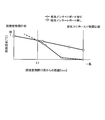
- FIG. 2 is a graph showing the relationship between the distance from the opening on the combustion chamber side in the intake port and the intake port wall surface temperature.
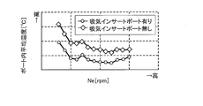
- FIG. 3 is a diagram showing an effect of lowering the average temperature in the port by inserting the intake insert port.
- FIG. 4 is a diagram showing the effect of improving the charging efficiency by inserting the intake insert port.
- FIG. 5 is a diagram showing an effect of improving torque by inserting an intake insert port.
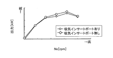
- FIG. 6 is a diagram showing the output improvement effect by inserting the intake insert port.
- FIG. 1 is a cross-sectional view of a cylinder head 1 according to a first embodiment of the present invention.
- the base material of the cylinder head 1 is an aluminum alloy, but is not limited thereto, and may be another alloy.
- a concave combustion chamber 9 is provided on the lower surface of the cylinder head 1 in the drawing (hereinafter simply referred to as “lower surface”). Inside the cylinder head 1 are formed an intake port 3 and an exhaust port 4 having one end opened to the combustion chamber 9 and the other end opened to a side surface of the cylinder head 1 (hereinafter also referred to as a cylinder head side surface).
- An intake manifold 2 communicating with the intake port 3 is connected to a side surface of the cylinder head where the intake port 3 opens.
- An exhaust manifold communicating with the exhaust port 4 is connected to the side surface of the cylinder head where the exhaust port 4 opens, but is omitted in FIG.
- an intake valve 5 and an exhaust valve 6 are arranged at openings of the intake port 3 and the exhaust port 4 to the combustion chamber 9, respectively.
- a coolant passage 8 for cooling the cylinder head 1 is formed in the cylinder head 1.
- a cylindrical intake insert port 7 made of a material having lower thermal conductivity and lower specific heat than the base material of the cylinder head 1 is inserted into the intake port 3, and the intake air is contained in the intake insert port 7. Pass the circumference side. That is, the intake insert port 7 functions as the intake port 3 while being inserted into the intake port 3. The range in which the intake insert port 7 is inserted will be described later.
- the material of the intake insert port 7 resin or ceramic can be used, but resin is used in this embodiment.
- an air layer is provided between the outer periphery of the intake insert port 7 and the wall surface of the intake port 3.
- the temperature of the cylinder head 1 rises as heat propagates from the combustion chamber 9. Although this temperature rise is suppressed by heat exchange with the coolant flowing through the coolant passage 8, the cylinder head 1 becomes higher than the intake air temperature. For this reason, the intake air receives heat from the wall surface of the intake port 3 and rises in temperature, leading to a decrease in filling efficiency and a deterioration in knock characteristics. Therefore, the intake insert port 7 is inserted into the intake port 3 in order to suppress heat transfer from the wall surface of the intake port 3 to the intake air.
- the base material of the cylinder head 1 is an aluminum alloy having excellent heat conductivity. Therefore, even if a part of the intake port 3 is heated by burned gas, the heat is generated in the cylinder. It diffuses to other parts of the head 1. The temperature of the cylinder head 1 is increased by the heat from the combustion chamber 9 but is cooled by the coolant, so that the upper limit value of the wall surface temperature of the intake port 3 is maintained even if heating with the burned gas is repeated. Is suppressed.
- the effect of suppressing the temperature rise of the intake air by inserting the intake insert port 7 is obtained when the temperature of the intake insert port 7 does not become higher than the base material temperature of the cylinder head 1. Therefore, as described below, a range for inserting the intake insert port 7 is set.
- FIG. 2 shows the relationship between the distance from the opening on the combustion chamber 9 side and the wall surface temperature in contact with the intake air (hereinafter also simply referred to as the wall surface temperature) when the intake insert port 7 is inserted and not inserted.
- the vertical axis represents the wall surface temperature
- the horizontal axis represents the distance from the combustion chamber side opening.
- the distance from the combustion chamber side opening is the distance along the axis C of the intake port 3.
- the wall surface temperature when the intake insert port 7 is inserted (also referred to as having an intake insert port) is the temperature of the inner peripheral surface of the intake insert port 7 and is not inserted (also referred to as having no intake insert port).
- the temperature is the temperature of the base material of the portion constituting the intake port 3.
- the combustion chamber side opening is the hottest, and the wall surface temperature gradually decreases as the distance from the combustion chamber side opening increases.
- the wall surface temperature is higher as it is closer to the combustion chamber 9.
- the opening on the intake manifold 2 side is lower in temperature than the case without the intake insert port 7, but as it approaches the combustion chamber 9, it approaches the wall surface temperature without the intake insert port 7 and from the combustion chamber side opening.
- the distance becomes shorter than L1 the temperature becomes higher than that without the intake insert port 7. The reason why the temperature from the combustion chamber side opening nearer than L1 is higher than that without the intake insert port 7 is due to the above-described heating by the reburning of burned gas.
- the intake insert port 7 is set so that the position of the distance L1 at which the wall surface temperature is the same with and without the intake insert port 7 is the end portion (hereinafter also referred to as the front end portion) on the combustion chamber 9 side. insert. That is, the range from the distance L1 to the intake manifold side opening is covered with the intake insert port 7.
- the burned-back amount of burned gas varies according to operating conditions such as engine load, rotation speed, and valve timing, and the wall surface temperatures of the intake port 3 and the intake insert port 7 also change according to the blow-back amount. Varies depending on the operating conditions.
- the distance L1 under the operating condition in which knocking occurs without the intake insert port 7 is the distance from the combustion chamber side opening to the tip of the intake insert port 7, and the intake insert port 7 is inserted. Avoid knocking.
- the effect of suppressing the rise in the temperature of the intake air by inserting the intake insert port 7, that is, the allowance for improving the knock margin, varies depending on the cross-sectional area, length, shape of the intake port 3 and other specifications of the internal combustion engine. , “Operating conditions under which knocking occurs” are determined by conformance.
- FIG. 3 is a diagram showing the relationship between the rotational speed of the internal combustion engine and the average temperature in the intake port 3 when the intake insert port 7 is provided and when the intake insert port 7 is not provided.
- the vertical axis represents the average temperature in the port
- the horizontal axis represents the rotational speed of the internal combustion engine. The reason why the average temperature in the port is used is that the effect of suppressing the increase in the temperature of the intake air by inserting the intake insert port 7 can be evaluated without measuring the temperature of the intake air flowing into the combustion chamber 9.
- the average temperature in the port is lower in the entire rotational speed region than when the intake insert port 7 is not provided.
- FIG. 4 is a graph showing the relationship between the rotational speed of the internal combustion engine and the charging efficiency when the intake insert port 7 is provided and when the intake insert port 7 is not provided.
- the vertical axis represents the charging efficiency
- the horizontal axis represents the rotational speed of the internal combustion engine.
- the charging efficiency is improved in almost the entire rotational speed region as compared with the case without the intake insert port 7. Specifically, an average of 1.5% is improved in the entire rotation speed region. This is because the intake air temperature is lowered over the entire rotational speed region by inserting the intake insert port 7.
- FIG. 5 shows the relationship between the torque of the internal combustion engine (crankshaft shaft torque) and the rotational speed
- FIG. 6 shows the relationship between the output of the internal combustion engine and the rotational speed.
- the horizontal axis represents the rotational speed
- the vertical axis represents the torque and the output, respectively.
- the torque is improved by about 1.2% on average over the entire rotation speed region, and the maximum output is improved by about 1.1%.
- the knock margin is improved by lowering the average temperature in the port, the ignition timing can be advanced and the compression ratio can be increased. Thereby, a torque and an output can be improved more.
- the intake insert port 7 has a lower thermal conductivity and a lower specific heat than the base material of the cylinder head 1. Then, during operation under an operating condition in which knocking occurs without the intake insert port 7, the temperature of the tip of the intake insert port 7 and the wall surface temperature of the intake port 3 at the position of the tip of the intake insert port 7, that is, the cylinder head 1 Is equal to the base metal temperature. Thereby, even when burnt gas blows back from the combustion chamber 9, the temperature of the intake insert port 7 can be prevented from becoming higher than the base material temperature of the cylinder head 1, so that the temperature rise of the intake air flowing into the combustion chamber 9 can be prevented. It is suppressed and the filling efficiency and the knock margin are improved.
- the intake insert port 7 of this embodiment not only has a lower thermal conductivity than the base material, but also has a smaller specific heat so that heat is dissipated as soon as the temperature rises. 3 can be prevented from being raised.
- the basic configuration of the cylinder head 1 is the same as that of the first embodiment, but the method for positioning the tip of the intake insert port 7 is different from that of the first embodiment.
- the distance L1 when operating under the operating condition in which the wall surface temperature of the intake port 3 is the highest without the intake insert port 7 is from the combustion chamber side end to the front end of the intake insert port 7. Distance.
- the operating condition in which the wall surface temperature of the intake port 3 is the highest is the operating condition in which the amount of burnt gas blowback is maximized. Specifically, it is a case where the valve timing is the low rotation speed / low load region and the valve overlap period is maximum within the changeable range.
- the maximum value of the intake air temperature can be suppressed by setting the distance from the combustion chamber side end of the front end of the intake insert port 7 to the distance L1 under the operating condition in which the wall surface temperature of the intake port 3 is the highest. it can.
- effects such as improvement of filling efficiency and improvement of knock margin can be obtained.
Landscapes
- Engineering & Computer Science (AREA)
- Chemical & Material Sciences (AREA)
- Combustion & Propulsion (AREA)
- Mechanical Engineering (AREA)
- General Engineering & Computer Science (AREA)
- Cylinder Crankcases Of Internal Combustion Engines (AREA)
Abstract
シリンダヘッドは、吸気マニホールドとの接続部と燃焼室とを連通する吸気ポートと、シリンダヘッドの母材よりも熱伝導率が低くかつ比熱が小さい材料で形成された筒状部材であって、吸気ポート内で吸気マニホールドとの接続部から燃焼室方向に延びて吸気ポートとして機能する吸気インサートポートとを備える。そして、シリンダヘッドは、所定の運転条件での運転時に、吸気インサートポートの燃焼室側端部の温度と、吸気インサートポートの燃焼室側端部位置におけるシリンダヘッドの母材温度とが等しい。
Description
本発明は、内燃機関のシリンダヘッドに関する。
内燃機関の運転中に、シリンダヘッドは燃焼室や排気マニホールドからの熱伝播により温度上昇し、これに伴ってシリンダヘッドに設けられた吸気ポートの壁面温度も上昇する。そして、吸気ポートの壁面温度が上昇することによって、内部を流れる吸入空気の温度が上昇すると、ノッキングが発生し易くなる。
そこで、吸気ポートに断熱機能を有する吸気インサートポートを挿入して吸気ポートの壁面と吸入空気との接触を防止し、吸入空気の温度上昇を抑制することがJP2008-144740Aに記載されている。
吸気ポート壁面から吸入空気への熱の伝達を防止するという観点からは、吸気ポート壁面と吸入空気との接触面積ができるだけ少なくなるように、つまり、吸気マニホールド側端部から燃焼室の近くまで吸気インサートポートを挿入することが望ましいように思われる。しかし、吸気インサートポートの先端が燃焼室から吹き返す既燃ガスにより加熱されると、吸気インサートポートは熱伝導率が低いため熱が先端に溜まり、また、冷却水で冷却されているシリンダヘッドとの熱交換もできない。これに対し、吸気インサートポートを挿入しない場合は、既燃ガスから受けた熱はシリンダヘッド全体へと逃げることができ、シリンダヘッドは冷却水により冷却されるため、吸気ポート壁面の温度上昇は抑制される。すなわち、吸気インサートポートを燃焼室の近くまで挿入すると、吸気インサートポートの先端温度がシリンダヘッドの母材温度より高くなり、吸入空気の温度上昇を抑制する効果が得られなくなるおそれがある。
そこで本発明は、吸入空気の温度上昇を抑制する効果が得られる吸気ポートを備える内燃機関のシリンダヘッドを提供することを目的とする。
本発明のある態様によれば、吸気マニホールドとの接続部と燃焼室とを連通する吸気ポートと、シリンダヘッドの母材よりも熱伝導率が低くかつ比熱が小さい材料で形成された筒状部材であって、吸気ポート内で吸気マニホールドとの接続部から燃焼室方向に延びて吸気ポートとして機能する吸気インサートポートと、を備える内燃機関のシリンダヘッドが提供される。
このシリンダヘッドは、所定の運転条件での運転時に、吸気インサートポートの燃焼室側端部の温度と、吸気インサートポートの燃焼室側端部位置におけるシリンダヘッドの母材温度とが等しい。
以下、添付図面を参照しながら本発明の実施形態について説明する。
(第1実施形態)
図1は、本発明の第1実施形態に係るシリンダヘッド1の断面図である。本実施形態では、シリンダヘッド1の母材をアルミニウム合金とするが、これに限られるわけではなく、他の合金等であっても構わない。
図1は、本発明の第1実施形態に係るシリンダヘッド1の断面図である。本実施形態では、シリンダヘッド1の母材をアルミニウム合金とするが、これに限られるわけではなく、他の合金等であっても構わない。
シリンダヘッド1の図中下側の面(以下、単に「下面」という)には、凹状の燃焼室9が設けられている。シリンダヘッド1の内部には、一端が燃焼室9に開口し、他端がシリンダヘッド1の側面(以下、シリンダヘッド側面ともいう)に開口する吸気ポート3及び排気ポート4が形成されている。吸気ポート3が開口するシリンダヘッド側面には、吸気ポート3と連通する吸気マニホールド2が接続されている。なお、排気ポート4が開口するシリンダヘッド側面には、排気ポート4と連通する排気マニホールドが接続されるが、図1では省略している。
一方、吸気ポート3及び排気ポート4の燃焼室9への開口部には、それぞれ吸気バルブ5、排気バルブ6が配置されている。
また、シリンダヘッド1の内部には、シリンダヘッド1を冷却するための冷却液通路8が形成されている。
吸気ポート3には、シリンダヘッド1の母材よりも熱伝導率が低くかつ比熱が小さい材料で形成された筒状の吸気インサートポート7が挿入されており、吸入空気は吸気インサートポート7の内周側を通過する。つまり、吸気インサートポート7は吸気ポート3に挿入された状態で、吸気ポート3として機能する。なお、吸気インサートポート7が挿入される範囲については後述する。
吸気インサートポート7の材料としては、樹脂又はセラミック等を用いることができるが、本実施形態では樹脂を用いる。なお、図1では省略しているが、吸気インサートポート7の外周と吸気ポート3の壁面との間には空気層が設けられている。
次に、吸気インサートポート7を挿入する目的、挿入する範囲について説明する。
機関運転中は、燃焼室9から熱が伝播することによってシリンダヘッド1の温度は上昇する。この温度上昇は冷却液通路8を流れる冷却液との熱交換によって抑制されるものの、シリンダヘッド1は吸入空気温度より高温になる。このため、吸入空気は吸気ポート3の壁面から熱を受けとって温度上昇し、充填効率の低下やノック特性の悪化を招くこととなる。そこで、吸気ポート3の壁面から吸入空気への熱の伝達を抑制するために、吸気インサートポート7を吸気ポート3に挿入する。
ところで、吸気ポート3の壁面から吸入空気への熱の伝達を抑制するという観点からは、吸気ポート3のできるだけ広い範囲が吸気インサートポート7で覆われることが望ましいようにも思われる。しかし、吸気インサートポート7で吸気ポート3の全域を覆うと、例えばバルブオーバーラップ期間を有するバルブタイミングで運転した場合に、吸気バルブ5の開弁時に燃焼室9から吹き返す既燃ガスによって、吸気インサートポート7が加熱される。吸気インサートポート7は熱伝導率が低いので、加熱された部分から他の部分へ熱が拡散しにくく、また、シリンダヘッド1との熱交換もできない。このため、燃焼室9の近くで既燃ガスに加熱された部分に熱が溜まり易く、既燃ガスが吹き返す度に温度上昇してしまう。吸気インサートポート7が温度上昇すれば、その内側を通過する吸入空気の温度も上昇してしまう。すなわち、吸気インサートポート7を燃焼室9の近くまで挿入すると、既燃ガスの吹き返しにより吸気インサートポート7の燃焼室9に近い部分がシリンダヘッド1の母材温度より高くなって、かえって吸入空気の温度上昇を招くおそれがある。
一方、吸気インサートポート7を挿入しない場合には、シリンダヘッド1の母材は熱の伝導性に優れるアルミニウム合金なので、既燃ガスにより吸気ポート3の一部が加熱されても、その熱はシリンダヘッド1の他の部位に拡散する。そして、シリンダヘッド1は燃焼室9からの熱により温度上昇しているが、冷却液により冷却されているので、既燃ガスによる加熱が繰り返し行われても、吸気ポート3の壁面温度の上限値は抑制される。
すなわち、吸気インサートポート7の挿入による吸入空気の温度上昇抑制効果が得られるのは、吸気インサートポート7の温度がシリンダヘッド1の母材温度より高くならない場合である。そこで、以下に説明するように、吸気インサートポート7を挿入する範囲を設定する。
図2は、吸気インサートポート7を挿入する場合と挿入しない場合の、燃焼室9側の開口部からの距離と、吸入空気に接触する壁面温度(以下、単に壁面温度ともいう)との関係を示す図であり、縦軸が壁面温度、横軸が燃焼室側開口部からの距離を示している。
なお、燃焼室側開口部からの距離は、吸気ポート3の軸線Cに沿う距離である。また、吸気インサートポート7を挿入する(吸気インサートポート有りともいう)場合の壁面温度とは、吸気インサートポート7の内周面の温度であり、挿入しない(吸気インサートポート無しともいう)場合の壁面温度とは、吸気ポート3を構成する部分の母材の温度である。
吸気インサートポート7無しの場合は、燃焼室側開口部が最も高温で、燃焼室側開口部からの距離が長くなるほど徐々に壁面温度は低くなる。
一方、吸気インサートポート7有りの場合も、燃焼室9に近くなるほど壁面温度は高くなっている。ただし、吸気マニホールド2側の開口部では吸気インサートポート7無しの場合に比べて低温だが、燃焼室9に近づくに連れて吸気インサートポート7無しの場合の壁面温度に近づき、燃焼室側開口部からの距離がL1より短くなると、吸気インサートポート7無しの場合よりも高温になる。燃焼室側開口部からの距離がL1より近い部分で吸気インサートポート7無しの場合より高温になるのは、上述した既燃ガスの吹き返しによる加熱によるものである。
そこで、吸気インサートポート7有りの場合と無しの場合の壁面温度が等しくなる距離L1の位置が、燃焼室9側の端部(以下、先端部ともいう)となるように、吸気インサートポート7を挿入する。つまり、距離L1から吸気マニホールド側開口部までの範囲を吸気インサートポート7で覆う。
これにより、距離L1未満の範囲については、吸気インサートポート7を挿入することでかえって吸入空気の温度が上昇してしまう事態を回避でき、距離L1以上の範囲については、吸気インサートポート7による吸入空気温度の上昇抑制効果が得られる。すなわち、吸気インサートポート7有りの場合は、燃焼室9に流入する吸入空気の温度が、吸気インサートポート7無しの場合に比べて低くなる。その結果、充填効率の向上やノック余裕度の向上等の効果が得られる。
ところで、既燃ガスの吹き返し量は、機関負荷、回転速度及びバルブタイミングといった運転条件に応じて変動し、吹き返し量に応じて吸気ポート3及び吸気インサートポート7の壁面温度も変化するので、距離L1も運転条件に応じて変動する。
そこで本実施形態では、吸気インサートポート7無しではノッキングが発生する運転条件における距離L1を、燃焼室側開口部から吸気インサートポート7の先端部までの距離とし、吸気インサートポート7を挿入することによってノッキング発生を回避する。
なお、吸気インサートポート7を挿入することによる吸入空気の温度上昇抑制効果、つまりノック余裕度の向上代は、吸気ポート3の流路断面積、長さ、形状、その他内燃機関の仕様により異なるので、「ノッキングが発生する運転条件」は適合により定める。
上記のように吸気インサートポート7の先端部の位置を設定した場合の効果について説明する。
図3は、吸気インサートポート7有りの場合及び吸気インサートポート7無しの場合についての、内燃機関の回転速度と吸気ポート3のポート内平均温度との関係を示す図である。縦軸がポート内平均温度、横軸が内燃機関の回転速度である。ポート内平均温度を用いるのは、燃焼室9に流入した吸入空気温度を測定することなく、吸気インサートポート7を挿入することによる吸入空気の温度上昇抑制効果を評価できるからである。
図3に示すように、吸気インサートポート7有りの場合は、吸気インサートポート7無しの場合に比べて、全回転速度領域でポート内平均温度が低くなっている。
図4は、吸気インサートポート7有りの場合及び吸気インサートポート7無しの場合についての、内燃機関の回転速度と充填効率との関係を示す図である。縦軸が充填効率、横軸が内燃機関の回転速度である。
吸気インサートポート7有りの場合は、吸気インサートポート7無しの場合に比べて、ほぼ全回転速領域で充填効率が向上している。具体的には、全回転速度領域で平均すると1.5%向上している。これは、吸気インサートポート7を挿入することで、吸入空気温度が全回転速度領域にわたって低下したためである。
また、充填効率が向上することで、機関出力も向上する。図5は内燃機関のトルク(クランクシャフトの軸トルク)と回転速度との関係を、図6は内燃機関の出力と回転速度との関係を、示す図である。いずれも、横軸は回転速度であり、縦軸はそれぞれトルク、出力である。
吸気インサートポート7を挿入することで、トルクが全回転速度領域で平均すると1.2%程度向上し、最高出力が1.1%程度向上している。
また、ポート内平均温度が低下することでノック余裕度が向上するので、点火時期を進角したり、圧縮比を高めたりすることもできる。これにより、トルクや出力をより向上させることができる。
以上のように本実施形態によれば、次のような効果が得られる。
吸気インサートポート7は、シリンダヘッド1の母材より熱伝導率が低く、かつ比熱が小さい。そして、吸気インサートポート7無しではノッキングが発生する運転条件での運転時に、吸気インサートポート7の先端部の温度と、吸気インサートポート7の先端部位置における吸気ポート3の壁面温度、つまりシリンダヘッド1の母材温度とが等しい。これにより、燃焼室9から既燃ガスが吹き返す場合でも、吸気インサートポート7の温度がシリンダヘッド1の母材温度より高くなることを防止できるので、燃焼室9に流入する吸入空気の温度上昇が抑制され、充填効率やノック余裕度が向上する。
また、吸気ポート3の壁面と吸気インサートポート7との間に空気層を設けることで、吸気ポート3の壁面から吸気インサートポート7へ熱が伝わりにくくなり、吸気インサートポート7を挿入することによる吸入空気の温度上昇抑制効果がさらに向上する。ところで、熱伝導率を母材より低くしても、熱伝導率がゼロになるわけではなく、高温の排気に曝されることで時間の経過とともに温度が上昇してしまう。このため、吸気インサートポート7の熱容量が大きくなるほど、一度上がってしまった温度を下げる為の放熱量が大きくなり、吸気ポート3の温度を上げてしまう時間の方が長くなってしまう可能性がある。しかし本実施形態の吸気インサートポート7は、母材よりも熱伝導率が低いだけでなく、温度上昇してもすぐに放熱されるよう比熱を小さくしているので、上記のようにかえって吸気ポート3の温度を上げてしまうことを防止できる。
(第2実施形態)
本実施形態は、基本的なシリンダヘッド1の構成は第1実施形態と同様であるが、吸気インサートポート7の先端部の位置決め方法が第1実施形態とは異なる。
本実施形態は、基本的なシリンダヘッド1の構成は第1実施形態と同様であるが、吸気インサートポート7の先端部の位置決め方法が第1実施形態とは異なる。
本実施形態では、吸気インサートポート7無しの状態で、吸気ポート3の壁面温度が最も高くなる運転条件で運転する場合の上記距離L1を、燃焼室側端部から吸気インサートポート7の先端部までの距離とする。
なお、吸気ポート3の壁面温度が最も高くなる運転条件とは、既燃ガスの吹き返し量が最大となる運転条件である。具体的には、低回転速度・低負荷領域であって、かつ、バルブオーバーラップ期間が変更可能範囲内で最大となるバルブタイミングである場合である。
吸気インサートポート7の先端部の燃焼室側端部からの距離を、吸気ポート3の壁面温度が最も高くなる運転条件における上記距離L1とすることにより、吸入空気温度の最高値を抑制することができる。その結果、第1実施形態と同様に充填効率の向上やノック余裕度の向上といった効果が得られる。
以上、本発明の実施形態について説明したが、上記実施形態は本発明の適用例の一部を示したに過ぎず、本発明の技術的範囲を上記実施形態の具体的構成に限定する趣旨ではない。
本願は2013年6月12日に日本国特許庁に出願された特願2013-123605に基づく優先権を主張し、この出願の全ての内容は参照により本明細書に組み込まれる。
Claims (3)
- 吸気マニホールドとの接続部と燃焼室とを連通する吸気ポートと、
シリンダヘッドの母材よりも熱伝導率が低くかつ比熱が小さい材料で形成された筒状部材であって、前記吸気ポート内で前記吸気マニホールドとの接続部から前記燃焼室の方向に延びて吸気ポートとして機能する吸気インサートポートと、
を備える内燃機関のシリンダヘッドにおいて、
所定の運転条件での運転時に、前記吸気インサートポートの前記燃焼室側端部の温度と、前記吸気インサートポートの前記燃焼室側端部位置における前記シリンダヘッドの母材温度とが等しい内燃機関のシリンダヘッド。 - 請求項1に記載の内燃機関のシリンダヘッドにおいて、
前記所定の運転条件は、ノッキングが発生する運転条件である内燃機関のシリンダヘッド。 - 請求項1に記載の内燃機関のシリンダヘッドにおいて、
前記所定の運転条件は、前記吸気インサートポートの前記燃焼室側端部の温度が最も高くなる運転条件である内燃機関のシリンダヘッド。
Priority Applications (1)
| Application Number | Priority Date | Filing Date | Title |
|---|---|---|---|
| JP2015522617A JP5994940B2 (ja) | 2013-06-12 | 2014-04-14 | 内燃機関のシリンダヘッド |
Applications Claiming Priority (2)
| Application Number | Priority Date | Filing Date | Title |
|---|---|---|---|
| JP2013123605 | 2013-06-12 | ||
| JP2013-123605 | 2013-06-12 |
Publications (1)
| Publication Number | Publication Date |
|---|---|
| WO2014199717A1 true WO2014199717A1 (ja) | 2014-12-18 |
Family
ID=52022020
Family Applications (1)
| Application Number | Title | Priority Date | Filing Date |
|---|---|---|---|
| PCT/JP2014/060653 Ceased WO2014199717A1 (ja) | 2013-06-12 | 2014-04-14 | 内燃機関のシリンダヘッド |
Country Status (2)
| Country | Link |
|---|---|
| JP (1) | JP5994940B2 (ja) |
| WO (1) | WO2014199717A1 (ja) |
Citations (5)
| Publication number | Priority date | Publication date | Assignee | Title |
|---|---|---|---|---|
| JPS6375531U (ja) * | 1986-11-07 | 1988-05-19 | ||
| JPH06185318A (ja) * | 1992-12-16 | 1994-07-05 | Nissan Motor Co Ltd | 内燃機関の排気弁装置 |
| JP2003056399A (ja) * | 2001-08-15 | 2003-02-26 | Nissan Motor Co Ltd | 内燃機関の吸気ポート断熱構造および吹き返し流量推定方法 |
| JP2004204796A (ja) * | 2002-12-26 | 2004-07-22 | Nissan Motor Co Ltd | 内燃機関の吸気ポート構造 |
| JP2012072749A (ja) * | 2010-09-30 | 2012-04-12 | Mazda Motor Corp | リーンバーンエンジン |
-
2014
- 2014-04-14 WO PCT/JP2014/060653 patent/WO2014199717A1/ja not_active Ceased
- 2014-04-14 JP JP2015522617A patent/JP5994940B2/ja active Active
Patent Citations (5)
| Publication number | Priority date | Publication date | Assignee | Title |
|---|---|---|---|---|
| JPS6375531U (ja) * | 1986-11-07 | 1988-05-19 | ||
| JPH06185318A (ja) * | 1992-12-16 | 1994-07-05 | Nissan Motor Co Ltd | 内燃機関の排気弁装置 |
| JP2003056399A (ja) * | 2001-08-15 | 2003-02-26 | Nissan Motor Co Ltd | 内燃機関の吸気ポート断熱構造および吹き返し流量推定方法 |
| JP2004204796A (ja) * | 2002-12-26 | 2004-07-22 | Nissan Motor Co Ltd | 内燃機関の吸気ポート構造 |
| JP2012072749A (ja) * | 2010-09-30 | 2012-04-12 | Mazda Motor Corp | リーンバーンエンジン |
Also Published As
| Publication number | Publication date |
|---|---|
| JPWO2014199717A1 (ja) | 2017-02-23 |
| JP5994940B2 (ja) | 2016-09-21 |
Similar Documents
| Publication | Publication Date | Title |
|---|---|---|
| KR20160063147A (ko) | 워터자켓을 갖는 배기매니폴드 일체형 실린더헤드 | |
| JP5617785B2 (ja) | 内燃機関 | |
| CN110630400A (zh) | 用于气体发动机的活塞及具有其的气体发动机 | |
| JP2011169232A (ja) | 内燃機関 | |
| JP5843757B2 (ja) | ターボチャージャ | |
| JP6307811B2 (ja) | エンジンの制御装置 | |
| JP5994940B2 (ja) | 内燃機関のシリンダヘッド | |
| JP5293842B2 (ja) | 内燃機関のピストン | |
| US20170292470A1 (en) | Internal combustion engine | |
| JP2007100612A (ja) | 副室式内燃機関 | |
| JP2011140902A (ja) | 内燃機関の制御装置 | |
| JP7003709B2 (ja) | スパークプラグ | |
| JP7339157B2 (ja) | 副室式点火装置 | |
| JP2004239126A (ja) | 筒内直接噴射式火花点火内燃機関のシリンダヘッドおよびその製造方法 | |
| CN210264936U (zh) | 一种防止天然气发动机不正常燃烧的气缸盖 | |
| JP7277298B2 (ja) | スパークプラグ | |
| JP2012082721A (ja) | 内燃機関の制御装置及び制御方法 | |
| JP2011214564A (ja) | 内燃機関の制御装置 | |
| JP2018123688A (ja) | エンジン燃焼室構造 | |
| CN205243660U (zh) | 一种摩托车发动机气缸头总成 | |
| JPS6313384Y2 (ja) | ||
| JP4848474B1 (ja) | 火花点火式4サイクルエンジン | |
| JP2007285280A (ja) | 内燃機関の制御装置 | |
| JP2011099379A (ja) | 内燃機関 | |
| JP6281585B2 (ja) | 内燃機関の吸排気構造 |
Legal Events
| Date | Code | Title | Description |
|---|---|---|---|
| 121 | Ep: the epo has been informed by wipo that ep was designated in this application |
Ref document number: 14811495 Country of ref document: EP Kind code of ref document: A1 |
|
| ENP | Entry into the national phase |
Ref document number: 2015522617 Country of ref document: JP Kind code of ref document: A |
|
| NENP | Non-entry into the national phase |
Ref country code: DE |
|
| 122 | Ep: pct application non-entry in european phase |
Ref document number: 14811495 Country of ref document: EP Kind code of ref document: A1 |