WO2014199707A1 - 媒体処理装置 - Google Patents
媒体処理装置 Download PDFInfo
- Publication number
- WO2014199707A1 WO2014199707A1 PCT/JP2014/060028 JP2014060028W WO2014199707A1 WO 2014199707 A1 WO2014199707 A1 WO 2014199707A1 JP 2014060028 W JP2014060028 W JP 2014060028W WO 2014199707 A1 WO2014199707 A1 WO 2014199707A1
- Authority
- WO
- WIPO (PCT)
- Prior art keywords
- medium
- unit
- processing apparatus
- banknote
- storage
- Prior art date
- Legal status (The legal status is an assumption and is not a legal conclusion. Google has not performed a legal analysis and makes no representation as to the accuracy of the status listed.)
- Ceased
Links
Images















Classifications
-
- G—PHYSICS
- G07—CHECKING-DEVICES
- G07D—HANDLING OF COINS OR VALUABLE PAPERS, e.g. TESTING, SORTING BY DENOMINATIONS, COUNTING, DISPENSING, CHANGING OR DEPOSITING
- G07D11/00—Devices accepting coins; Devices accepting, dispensing, sorting or counting valuable papers
- G07D11/10—Mechanical details
- G07D11/14—Inlet or outlet ports
Definitions
- the present invention relates to a medium processing apparatus and can be applied to, for example, a banknote processing apparatus that handles banknotes as a medium.
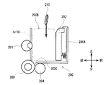
- the banknote handling apparatus is provided with a depositing unit 200 as shown in FIG.
- the depositing unit 200 has a box-shaped storage unit 200A having an open upper surface, and a part of the opening of the storage unit 200A serves as a bill insertion slot 200B.
- a bill intake port 200C inserted into the storage unit 200A is provided at one end side (for example, the rear end side) thereof.
- the back end side said here is a back
- the depositing unit 200 is provided with a pickup roller 201 so that a part thereof protrudes from the rear wall of the storage unit 200A.
- the depositing unit 200 is provided with a plate-shaped bill press 202 that can slide in the storage unit 200A in the front-rear direction in a state parallel to the rear wall of the storage unit 200A.
- An opening in a portion between the bill press 202 and the rear wall of the storage unit 200A is an insertion port 200B.
- a feed roller 203 and a gate roller 204 are arranged opposite to each other in the front-rear direction near the lower portion of the intake port 200C.
- a shutter 205 that is slidable in the direction in which the insertion port 200B is exposed and covered is provided on the upper side of the deposit unit 200.
- the conventional banknote handling apparatus has such a depositing unit 200, and at the time of depositing transaction, as shown in FIG. 31, the shutter 205 is opened to expose the insertion slot 200B of the depositing unit 200.
- the bill processing apparatus places the bill press 202 in a predetermined position in the vicinity of the front wall of the storage unit 200A (also referred to as a deposit start slide position) before opening the shutter 205 so that the bill can be easily inserted into the insertion port 200B.
- the charging port 200B is fully opened (or almost fully opened).
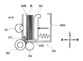
- the user inserts the bill BL into the area Ar10 (also referred to as a bill storage area) between the bill press 202 and the rear wall of the storage section 200A from the insertion port 200B.
- the area Ar10 also referred to as a bill storage area
- the banknote handling apparatus closes the shutter 205 to cover the insertion port 200 ⁇ / b> B of the depositing unit 200 and moves the bill press 202 closer to the rear wall of the storage unit 200 ⁇ / b> A (this direction is hereinafter referred to as “closed”). Slide in the direction).
- the banknote handling apparatus presses the banknote BL against the pickup roller 201 by the bill press 202 and holds the bill BL between the bill press 202 and the pickup roller 201.
- the banknote handling apparatus takes the banknote BL pressed against the pickup roller 201 downward by synchronizing the pickup roller 201 and the feed roller 203 and rotating them clockwise in the figure. Feed out to mouth 200C.
- the bills BL fed out to the take-in port 200C are separated one by one by the feed roller 203 and the gate roller 204, and taken into the bill processing apparatus from the take-in port 200C.
- the banknote handling apparatus takes in the banknotes BL inserted into the depositing unit 200 in this way one by one (see, for example, JP 2011-8412 A).
- the bill processing apparatus deposits the bill press 202 again with the shutter 205 closed as shown in FIG. Slide to the start slide position and wait for the next transaction.
- FIG. 36 shows the depositing unit 200 without the shutter 205.
- this depositing unit 200 there is nothing that covers the insertion port 200B of the depositing unit 200 in the standby state, and therefore, the charging unit 200B is exposed in a fully opened state.
- the foreign object 210 enters the banknote storage area Ar10 and the user does not notice this and performs the next transaction, the foreign object 210 is taken in the inlet. There is a possibility of entering between the feed roller 203 and the gate roller 204 from 200C.
- the present invention takes the above points into consideration, and intends to propose a medium processing apparatus that can prevent apparatus abnormalities while having a simple configuration.
- the storage unit has an opening serving as a medium input port, stores a medium input from the input port, a wall portion on one end side and a wall portion on the other end side in the storage unit
- a medium press unit that presses the medium input from the input port against the wall portion on the other end side of the storage unit, and the input port is a wall unit on the other end side of the storage unit.
- the medium inserted from the inlet is stored in the medium storage area between the wall on the other end of the storage unit and the medium press, and the medium is removed from the inlet.
- the medium press section is positioned at the first position when the medium to be loaded is placed, and the medium press section is placed inside the storage section from the first position so that the size of the slot is narrower than that when the medium is loaded during standby. It was made to position in the 2nd position located in the other end side.
- the medium press portion is positioned so that the size of the inlet is smaller than that when the medium is inserted. In this way, even when there is no shutter that covers the insertion port, it is possible to prevent foreign matter from entering the storage unit from the insertion port during standby.
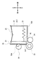
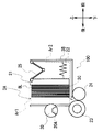
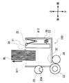
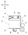
- composition (2) of a connecting part in a 1st embodiment It is an approximate line top view showing composition (2) of a connecting part in a 1st embodiment. It is an approximate line sectional view showing composition (2) of a connecting part in a 1st embodiment.
- payment part It is a basic diagram explaining the operation
- payment part It is a basic diagram which shows the internal structure of the banknote processing apparatus in 2nd Embodiment. It is a basic diagram which shows the structure of the deposit or withdrawal part in 2nd Embodiment. It is a basic diagram explaining the payment operation
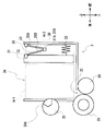
- FIG. 1 the external appearance structure of the banknote processing apparatus 1 is shown.
- the banknote handling apparatus 1 is a staff operation type terminal operated by a staff of a financial institution (for example, a reception counter staff), and performs banknote deposit and withdrawal processing based on an operation of the staff (user).
- the left side when viewed from the front of the banknote processing apparatus 1 is the left side of the banknote processing apparatus 1
- the right side when viewed from the front of the banknote processing apparatus 1 is the right side of the banknote processing apparatus 1.
- the direction from the left side to the right side of the banknote processing apparatus 1 is the right direction
- the direction from the right side to the left side of the banknote processing apparatus 1 is the left direction
- the direction from the lower side to the upper side of the banknote processing apparatus 1 is the upward direction
- banknote processing The direction from the upper side to the lower side of the apparatus 1 is the downward direction
- the direction from the back side to the near side of the banknote handling apparatus 1 is the front direction
- the direction from the near side to the far side of the banknote handling apparatus 1 is the back direction.
- the banknote handling apparatus 1 has an input port 3A of a depositing unit 3 (see FIG. 2), a discharge port 4A of a dispensing unit 4 (see FIG. 2), a display unit 5 and an operation unit 6 at the upper end of the housing 2. Is provided.
- the depositing unit 3 When the deposited banknote is inserted from the insertion port 3A by the user, the depositing unit 3 separates the deposited banknote one by one and takes it into the banknote processing apparatus 1.
- the withdrawal unit 4 accumulates the withdrawal banknotes and allows the user to take out the banknotes from the outlet 4A.
- the display unit 5 includes a liquid crystal display, for example, and displays a menu screen, a result screen of various processes, and the like.
- the operation unit 6 includes, for example, a button, and receives an operation on the banknote processing apparatus 1.
- the display unit 5 and the operation unit 6 are provided separately, but the display unit 5 and the operation unit 6 are provided integrally using, for example, a liquid crystal display with a touch panel. Also good.
- the banknote handling apparatus 1 can communicate with a terminal or host computer of a financial institution via a network, send / receive various information to / from the terminal or host computer, or operate from the terminal side. You can also do it.
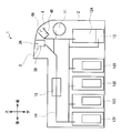
- a discrimination unit 10 In the housing 2 of the banknote handling apparatus 1, in addition to the depositing unit 3 and the withdrawal unit 4 described above, a discrimination unit 10, a temporary storage unit 11, banknote storages 12A to 12E, a rejection store 13 and a conveyance path 14 are provided. Is provided.
- the depositing unit 3 and the dispensing unit 4 are arranged in the front-rear direction so that the depositing unit 3 is on the rear side and the dispensing unit 4 is on the front side. .
- a temporary storage unit 11 is provided below the withdrawal unit 4, and a discrimination unit 10 is provided behind the temporary storage unit 11 and behind the deposit unit 3.
- banknote storages 12A to 12E are arranged in the front-rear direction in the lower part of the housing 2.
- a reject box 13 is provided below the banknote storage box 12A located on the front side.
- a conveyance path 14 that connects the depositing unit 3, the dispensing unit 4, the discrimination unit 10, the temporary storage unit 11, the bill storage units 12 ⁇ / b> A to 12 ⁇ / b> E, and the reject unit 13. .
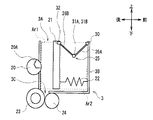
- the depositing unit 3 has a box-shaped storage unit 3B whose upper surface is open. A part of the opening of the storage portion 3B becomes the above-described charging port 3A.
- the depositing unit 3 separates the deposited banknotes inserted by the user into the storage unit 3B from the insertion slot 3A one by one and takes them into the banknote processing apparatus 1 at the time of deposit transaction.
- the depositing unit 3 is fixed to the banknote processing apparatus 1 in such a direction that the bottom surface of the storage unit 3B is substantially horizontal.
- the withdrawal part 4 has a box-shaped accumulation part 4B whose upper surface is open.
- the opening of the accumulation portion 4B becomes the above-described discharge port 4A.
- the withdrawal unit 4 collects the withdrawal banknotes conveyed from the banknote storages 12A to 12E and the like in the accumulation unit 4B during a withdrawal transaction, and allows the user to take out.
- dispensing unit 4 is fixed to the banknote handling apparatus 1 in a state where it is tilted forward so that the front side of the stacking unit 4B is positioned below the rear side.
- the discrimination unit 10 discriminates the denomination, authenticity, correctness, running state, and the like of banknotes conveyed one by one via the conveyance path 14. And this discrimination part 10 judges whether it is a normal banknote which can be handled or a reject banknote which cannot be handled for every banknote based on the discrimination result.
- the temporary holding unit 11 temporarily accumulates the banknotes taken from the depositing unit 3 and determined as normal banknotes by the discrimination unit 10.
- the banknotes accumulated in the temporary storage unit 11 in this manner are fed out from the temporary storage unit 11 and conveyed to the discrimination unit 10 after the transaction is established.
- the banknote storage 12A is stored.
- ⁇ 12E is transported and stored.
- the temporary storage unit 11 may be an accumulation type that sequentially stacks and accumulates banknotes, or may be a drum type in which banknotes are wound around a drum together with tape.
- Each of the banknote storages 12A to 12E stacks the banknotes conveyed via the conveyance path 14 so as to overlap each other in the vertical direction. Further, the banknote storages 12A to 12E not only store banknotes but also can feed banknotes accumulated inside to the transport path 14 one by one.
- banknote storages 12A to 12E are detachable from the banknote handling apparatus 1 individually.
- the reject box 13 accumulates banknotes that have been determined as reject banknotes by the discrimination unit 10.
- a control unit (not shown) for controlling the whole is provided at a predetermined location.
- the banknote processing apparatus 1 is configured as described above, and the control unit controls each unit based on the banknote discrimination result by the discrimination unit 10 and performs banknote depositing and withdrawal processing.
- the banknote processing apparatus 1 inputs a transaction item (in this case, deposit) etc. by the user via the operation unit 6 at the time of deposit transaction, and further inserts a bill into the deposit unit 3 from the insertion port 3A.
- the inserted banknotes are conveyed to the discrimination unit 10 one by one.
- the banknote handling apparatus 1 transports the banknotes determined to be normal banknotes by the discrimination unit 10 to the temporary storage unit 11 and temporarily stores them.
- the banknote determined to be a deposit reject banknote that is not suitable for depositing is returned to the withdrawal unit 4 and returned to the user.
- the banknotes stored in the temporary storage unit 11 are conveyed to the discrimination unit 10 to discriminate denominations, and according to the denominations, the respective banknote storages 12A to 12E. Transport to and store.
- the banknote processing apparatus 1 receives a transaction amount (in this case, withdrawal), a withdrawal amount, etc. by the user via the operation unit 6, and the necessary money according to the requested amount.
- a transaction amount in this case, withdrawal
- a withdrawal amount etc.
- the number of banknotes for each type is recognized, and banknotes are fed out from the banknote storage boxes 12A to 12E one by one in accordance with the number of banknotes for each denomination and conveyed to the discrimination unit 10.
- the banknote handling apparatus 1 transports the banknotes determined to be normal banknotes by the discrimination unit 10 to the withdrawal unit 4, while temporarily holding the banknotes determined to be withdrawal reject banknotes not suitable for withdrawal. It is transported to the section 11 and temporarily stored.
- the user receives banknotes corresponding to the withdrawal amount accumulated in the withdrawal unit 4.
- the banknote handling apparatus 1 transports the withdrawal reject banknotes stored in the temporary storage unit 11 to the reject store 13 for storage.
- the banknote handling apparatus 1 performs banknote depositing and withdrawal processing.
- banknote storage 12A located in the foremost side and the reject storage 13 located thereunder may be provided separately or may be integrated.
- the banknote storage 12 ⁇ / b> A may be used as a replenishment / recovery container that replenishes and collects banknotes to / from the banknote processing apparatus 1.
- the depositing unit 3 has a box-shaped storage unit 3B whose upper surface is open.
- a bill intake port 3C inserted into the storage unit 3B is provided at one end side (for example, the rear end side).
- the depositing unit 3 is provided with a pickup roller 20 so that a part protrudes from the rear wall of the storage unit 3B.
- a contact member 20A is provided along the outer peripheral surface so as to cover about a quarter of the entire outer periphery.
- the contact member 20 ⁇ / b> A is a member (for example, rubber) having a larger friction coefficient than the outer peripheral surface of the pickup roller 20.
- the pickup roller 20 rotates while contacting the contact member 20A with the bill.
- a total of two pick-up rollers 20 are provided on the left and right, respectively, and rotate in synchronization with the driving force of a motor (not shown).
- the depositing unit 3 is provided with a plate-shaped bill press 21 that can slide in the storage unit 3B in the front-rear direction in a state parallel to the rear wall of the storage unit 3B.
- the bill press 21 can be slid in a direction approaching the rear wall of the storage unit 3B (closed direction) and in a direction away from the rear wall (opening direction).
- the bill press 21 slides by a driving force of a motor (not shown).
- the opening between the bill press 21 and the rear wall of the storage unit 3B serves as a bill insertion slot 3A.
- region between the bill press 21 and the rear wall of the accommodating part 3B becomes banknote accommodation area
- a region between the front wall of the portion 3B is an internal mechanism region Ar2 in which an internal mechanism 22 such as a spring for sliding the bill press 21 is provided.
- a feed roller 23 and a gate roller 24 are arranged opposite to each other in the front-rear direction near the lower portion of the intake port 3C.
- the feed roller 23 rotates in synchronization with the pickup roller 20 by a driving force of a motor (not shown).
- the depositing unit 3 is provided with a folding bill press shutter 25 between the bill press 21 and the front wall of the storage unit 3B.
- the bill press shutter 25 is a shutter that covers the internal mechanism area Ar2 between the bill press 21 and the front wall of the storage unit 3B.
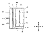
- the bill press shutter 25 has a structure in which two rectangular plate-like members 26A and 26B that are long in the left-right direction are connected in a hinge shape in the front-rear direction.
- the front member 26A is referred to as a first member 26A
- the rear member 26B is referred to as a second member 26B.
- the first member 26A has the same area as the front half of the opening on the upper surface of the storage portion 3B, and the second member 26B has the same area as the rear half of the opening. That is, the first member 26A and the second member 26B are two pieces and have an area that can cover the entire opening of the upper surface of the storage portion 3B.
- the central part of the front end of the first member 26A is connected to the upper end of the front wall of the storage part 3B via the connecting part 30.
- the first member 26A is connected to the front end portion of the second member 26B through the connecting portions 31A and 31B, respectively, at a location shifted to the left side by a predetermined distance from the center of the rear end portion and a location shifted to the right side. Yes.
- the second member 26B is connected to the rear end portion of the first member 26A via the connecting portions 31A and 31B, respectively, at a location shifted to the left side by a predetermined distance from the center of the front end portion and a location shifted to the right side.
- the second member 26 ⁇ / b> B has a central portion at the rear end portion connected to an upper end central portion on the front surface of the bill press 21 via a connecting portion 32.
- the connecting portion 30 protrudes from the two plate-like bearing portions 40A and 40B protruding from the front wall of the storage portion 3B and the front end portion of the first member 26A.
- the two plate-like bearing portions 41 ⁇ / b> A and 41 ⁇ / b> B and the shaft 42 are provided.
- Each of the four bearing portions 40A, 40B, 41A, 41B is provided with a circular shaft hole 43 penetrating in the left-right direction as a hole through which the shaft 42 passes.
- the interval between the two bearing portions 41A and 41B provided on the first member 26A side is wider than the interval between the two bearing portions 40A and 40B provided on the front wall side of the storage portion 3B.
- the four bearing portions 41A and 41B provided on the first member 26A side are positioned outside the two bearing portions 40A and 40B provided on the front wall side of the storage portion 3B, respectively. By inserting the shaft 42 into the shaft hole 43 of the bearing portions 40A, 40B, 41A, 41B, the first member 26A and the front wall of the storage portion 3B are connected.
- the first member 26A is connected to the front wall of the storage portion 3B so as to be rotatable about a shaft 42 extending in the left-right direction as a rotation axis.
- connecting parts 31A and 31B have the same configuration as the connecting part 30, the description thereof is omitted.
- the connecting portion 32 that connects the bill press 21 and the second member 26B has two plate-like bearing portions 44A and 44B protruding from the rear end portion of the second member 26B. And two plate-like bearing portions 45 ⁇ / b> A and 45 ⁇ / b> B projecting from the back surface of the bill press 21, and a shaft 42.
- the bearing portions 44A, 44B, 45A, 45B are provided with circular shaft holes 43 penetrating in the left-right direction as holes through which the shaft 42 passes. ing.
- the bearing portions 45A and 45B provided in the bill press 21 are provided with an elliptical shaft hole 46 penetrating in the left-right direction as a hole through which the shaft 42 passes.
- This shaft hole 46 is different from the other connecting portions 30, 31 ⁇ / b> A, and 31 ⁇ / b> B in that the shaft hole 46 is not circular but elliptical.
- the interval between the two bearing portions 45A and 45B provided on the bill press 21 side is wider than the interval between the two bearing portions 44A and 44B provided on the second member 26B side.
- the second member 26B is connected to the bill press 21 so as to be rotatable about a shaft 42 extending in the left-right direction as a rotation axis.
- the shaft hole 46 provided in each of the two bearing portions 45A and 45B on the bill press 21 side is longer in the front-rear direction than the cross section of the shaft 42. It is oval.
- the shaft hole 46 provided in each of the two bearing portions 45A and 45B on the bill press 21 side is provided with a play so that the shaft 42 can be displaced not only in the forward and backward directions. .
- the bill press 21 can be inclined from the state parallel to the wall of the rear wall of the storage portion 3B so that the left end is shifted rearward and the right end is shifted forward, or vice versa. Yes.
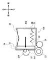
- the bill press shutter 25 is configured as described above. As shown in FIG. 3, when the bill press 21 is positioned in the vicinity of the front wall of the storage portion 3B, the front end of the first member 26A and the second member 26B It is in a state where it is closed and folded so as to be close to the rear end.
- the connecting portions 31A and 31B that connect the first member 26A and the second member 26B are located below the connecting portions 30 and 32. That is, the bill press shutter 25 is folded into a V shape.
- the bill press shutter 25 is developed so as to widen the V-shaped opening.
- the bill press shutter 25 is unfolded from the folded state as the bill press 21 slides in the closing direction, and an internal mechanism region between the bill press 21 and the front wall of the storage unit 3B.
- the upper part of Ar2 is always covered.
- the depositing unit 3 in the standby state is in a state where the bill press 21 is pressed against and brought into contact with the pickup roller 20, as shown in FIG.
- the position of the bill press 21 at this time is set as a standby slide position as the second position.
- the insertion port 3A which is an opening between the bill press 21 and the rear wall of the storage unit 3B, is the narrowest.
- the insertion slot 3A at this time is narrower than the thickness of a coin (for example, a 10-yen coin) assumed as a foreign object and is in a substantially closed state.
- the bill storage area Ar1 is also the narrowest.
- the banknote handling apparatus 1 can prevent foreign matters such as coins from entering the banknote storage area Ar1 from the insertion port 3A of the depositing unit 3 when the depositing unit 3 is in a standby state.
- the banknote processing apparatus 1 can also prevent foreign matter from entering the internal mechanism area Ar2 of the depositing unit 3 when the depositing unit 3 is in a standby state.
- the banknote handling apparatus 1 slides the bill press 21 in the opening direction (forward) from the standby slide position and stops it at a predetermined position near the front wall of the storage unit 3B. At this time, the position where the bill press 21 is stopped is set as a deposit start slide position as the first position.
- the insertion port 3A which is an opening between the bill press 21 and the rear wall of the storage unit 3B, gradually expands and becomes the widest and fully opened when the bill press 21 reaches the deposit start slide position. It becomes.
- the banknote handling apparatus 1 inserts banknotes in a deposit transaction
- the slot 3A is fully opened so that the banknotes can be easily inserted.
- the banknote processing apparatus 1 can also make a user recognize easily and reliably that a banknote should just be inserted from this insertion port 3A by fully opening the insertion port 3A.
- the insertion port 3A is fully opened here, it is not always necessary to fully open it. In short, it is only necessary to make the insertion port 3A as wide as possible so that it is easy to insert banknotes.
- the bill processing apparatus 1 recognizes that the bill BL is inserted from the insertion slot 3A into the bill storage area Ar1 by a sensor (not shown). To do.
- the banknote handling apparatus 1 slides the bill press 21 at the deposit start slide position in the closing direction.
- the bill press shutter 25 expands while covering the upper part of the internal mechanism area Ar2, so that the internal mechanism area Ar2 is always closed by the bill press shutter 25.
- the banknote handling apparatus 1 presses the bill BL inserted into the bill storage area Ar ⁇ b> 1 against the pickup roller 20 by the bill press 21 and sandwiches it between the bill press 21 and the pickup roller 20. .
- the bill press 21 can be inclined with respect to the wall surface of the rear wall of the storage portion 3B.
- the bill press 21 for example, as shown in FIGS. 11A to 11C, even when there is a difference in the thickness of the banknote bundle between the left and right due to the type and state of the inserted banknote, Since the posture can be tilted accordingly, a bundle of banknotes can be sandwiched between the pickup roller 20 more reliably.
- the pickup roller 20 is in the standby state in advance when it is in a standby state, and when it starts taking in banknotes in the deposit transaction (hereinafter referred to as the take-in start rotation position). ) And is stopped at this take-in start rotation position.
- the take-up rotation position is such that the one end in the circumferential direction of the contact member 20A is located at the contact point between the pickup roller 20 and the bill BL, and the other end in the circumferential direction is located above the one end. This is the rotation position when rotated.
- the one end in the circumferential direction referred to here is an end (referred to as a tip) that is located first when viewed from the rotation direction when the contact member 20A is rotated clockwise together with the pickup roller 20 in the figure.
- the other end in the circumferential direction is an end located later (referred to as a rear end) when viewed from the rotation direction.
- the banknote processing apparatus 1 rotates the pick-up roller 20 stopped at the take-in start rotation position clockwise in the figure, and synchronizes with the rotation of the pick-up roller 20.
- the feed roller 23 is rotated.
- the pickup roller 20 rotates while bringing the contact member 20A from the front end to the rear end into contact with the innermost banknote BL inserted in the banknote storage area Ar1.
- the innermost banknote BL is fed out to the lower intake 3C by friction with the contact member 20A.
- the bill BL fed out to the entrance 3C is separated from other bills BL by the feed roller 23 and the gate roller 24, and taken into the bill processing apparatus 1 from the entrance 3C.
- the banknote handling apparatus 1 rotates the pickup roller 20 of the depositing unit 3 from the take-in start rotation position at the time of deposit transaction, so that the front end to the rear end of the contact member 20A is turned into the backmost banknote BL.
- the innermost banknote BL can be reliably separated and taken in one by one.
- the banknote handling apparatus 1 continues to rotate the pickup roller 20 and the feed roller 23 so that the banknotes BL inserted into the banknote storage area Ar1 one by one in the same manner as the first banknote BL. I will take it in.
- the banknote processing apparatus 1 will recognize this by the sensor which is not shown in figure, if it finishes taking in all the banknotes BL thrown into the deposit part 3, as shown in FIG.
- the banknote processing apparatus 1 slides the bill press 21 in the opening direction (forward) and stops it at a predetermined position. At this time, the position where the bill press 21 is stopped is set as a retraction slide position as the third position.
- the retreat slide position may be any position as long as the bill press 21, the pickup roller 20, and the contact member 20A do not contact each other, and may be the same position as the deposit start slide position or after the storage unit 3B from the deposit start slide position. It may be a position close to the wall.
- the bill processing apparatus 1 moves the pickup roller 20 to the take-in start rotation position in preparation for the next transaction as shown in FIG. Rotate to stop.
- the bill processing apparatus 1 rotates the pickup roller 20 to the take-in start rotation position after separating the bill press 21 from the pickup roller 20 and the contact member 20A.
- the bill processing apparatus 1 rotates the pickup roller 20 after separating the bill press 21 from the pickup roller 20 and the contact member 20A, thereby accurately adjusting the pickup roller 20 to the take-in start rotation position. be able to.
- the banknote handling apparatus 1 again slides the bill press 21 in the closing direction and presses the bill press 21 against the pickup roller 20 (that is, the bill press 21 is positioned at the standby slide position). Is in a standby state.
- the above operation is the operation of the depositing unit 3 at the time of deposit transaction.
- the bill processing apparatus 1 places the bill press 21 at the standby slide position and presses it against the pickup roller 20 so that the insertion port 3A is The inlet 3A is narrowed so as to be almost closed.
- the bill press 21 is slid in the opening direction from the standby slide position to widen the insertion port 3A.
- the banknote handling apparatus 1 widens the insertion slot 3A in order to make it easier to insert banknotes when inserting banknotes in deposit transactions, while banknotes in deposit transactions in order to prevent foreign objects from entering during standby.
- the inlet 3A is made narrower than that at the time of charging.
- the banknote handling apparatus 1 can prevent foreign matter from entering the banknote storage area Ar1 from the insertion port 3A of the depositing unit 3 during standby when no deposit transaction is performed.
- the banknote handling apparatus 1 covers the internal mechanism area Ar2 as the bill press 21 slides in the closing direction above the internal mechanism area Ar2 between the bill press 21 and the front wall of the storage unit 3B.
- a bill press shutter 25 is provided to be developed on the screen.
- the banknote handling apparatus 1 can also prevent foreign matter from entering the internal mechanism area Ar2 during standby.
- the banknote handling apparatus 1 is set in advance so that the pickup roller 20 is set to the optimum take-up start rotation position when starting the taking-in of the banknote in the deposit transaction in advance in preparation for the next deposit transaction. did.
- the banknote processing apparatus 1 does not need to perform the operation
- the banknote handling apparatus 1 when the depositing unit 3 is in a standby state, the banknote handling apparatus 1 once takes the pick-up roller 20 in the state where the bill press 21 is once slid to the retracted slide position and separated from the pick-up roller 20. I tried to match.
- the banknote handling apparatus 1 can accurately adjust the pickup roller 20 to the take-in start rotation position.
- the banknote handling apparatus 1 can prevent foreign matter from entering the storage portion 3B of the depositing unit 3 from the insertion port 3A during standby without a shutter that covers the insertion port 3A.
- the banknote handling apparatus 1 can prevent a foreign matter from entering between the feed roller 203 and the gate roller 204 from the intake port 3C of the storage unit 3B, thereby avoiding a situation that causes an apparatus abnormality.
- the banknote handling apparatus 1 can prevent the apparatus from being abnormal due to the entry of foreign matter, while having a simple configuration.
- the configuration other than the deposit / withdrawal unit 100 of the banknote handling apparatus 101 is the same as that of the banknote handling apparatus 1 of the first embodiment. Is omitted.
- the configuration of the depositing / withdrawing unit 100 is the same as that of the depositing unit 3, and thus detailed description thereof is omitted.
- the deposit / withdrawal unit 100 is fixed to the banknote processing apparatus 101 with the front side of the storage unit 3 ⁇ / b> B tilted forward so that the front side is positioned below the rear side.
- the storage unit 3B may be fixed to the banknote processing apparatus 101 in a direction in which the bottom surface is substantially horizontal.
- the input port 3A of the deposit / withdrawal unit 100 functions as an input port through which a user inserts banknotes during a deposit transaction, and functions as a discharge port for allowing the user to take out banknotes during a deposit transaction. Therefore, in the description of the withdrawal transaction, the input port 3A is referred to as the discharge port 3A.
- the storage unit 3B of the deposit / withdrawal unit 100 functions as a storage unit that stores banknotes inserted by the user at the time of deposit transaction, and functions as an accumulation unit that stacks banknotes to be taken out by the user at the time of deposit transaction. . Therefore, in the description of the withdrawal transaction, the storage unit 3B is referred to as a stacking unit 3B.
- the entrance 3 ⁇ / b> C of the deposit / withdrawal unit 100 functions as an entrance for taking in the banknotes inserted by the user into the banknote processing apparatus 101 during the deposit transaction, while in the banknote processing apparatus 101 during the withdrawal transaction. Functions as a payout port for paying out banknotes from the banknote storage area Ar1. Therefore, in the description of the withdrawal transaction, the intake port 3C is referred to as a payout port 3C.
- the deposit / withdrawal unit 100 is in a standby state except when performing deposit transactions and withdrawal transactions.
- the deposit / withdrawal unit 100 in the standby state is in a state where the bill press 21 is pressed against the pickup roller 20 (that is, in a state where it is positioned at the standby slide position).
- the discharge port 3A which is an opening between the bill press 21 and the rear wall of the stacking portion 3B is the narrowest.
- the discharge port 3A at this time is narrower than the thickness of a coin (for example, a 10-yen coin) assumed as a foreign object and is in a substantially closed state.
- the bill storage area Ar1 is also the narrowest.
- the banknote handling apparatus 101 can prevent foreign matters such as coins from entering the banknote storage area Ar1 from the outlet 3A of the deposit / withdrawal unit 100 when the deposit / withdrawal unit 100 is in a standby state. .
- the banknote handling apparatus 101 can also prevent foreign matter from entering the internal mechanism area Ar2 of the deposit / withdrawal unit 100 when the deposit / withdrawal unit 100 is in a standby state.
- the banknote processing apparatus 101 slides the bill press 21 in the opening direction (forward) and stops it at a predetermined position between the rear wall and the front wall of the storage unit 3B.
- the position at which the bill press 21 is stopped at this time is set as a withdrawal start slide position.
- the withdrawal start slide position is closer to the rear wall of the stacking portion 3B than the deposit start slide position (see FIG. 8) so that the bill storage area Ar1 does not become too large.
- the bill processing apparatus 101 When the bill processing apparatus 101 recognizes that the bill press 21 has reached the dispensing start slide position by a sensor (not shown), it rotates the pickup roller 20 in the opposite direction (counterclockwise in the figure) to the time of deposit transaction.
- the feed roller 23 is rotated in synchronization with the rotation of the pickup roller 20.
- the banknote handling apparatus 101 feeds out the banknotes BL one by one into the banknote storage area Ar1, the banknote BL at the backmost part (that is, the banknote BL fed out most recently).
- the bill press 21 is slid little by little in the opening direction as the number of banknotes BL fed out into the banknote storage area Ar1 increases so that the position of the leftmost banknote BL) in the figure is always the same position. .
- the banknote processing apparatus 101 slides the bill press 21 to an opening direction to the same position as a payment start slide position so that it may be easy to take out a banknote, after paying out banknote BL for money of withdrawal amount in banknote storage area Ar1. Stop. At this time, the discharge port 3A is fully opened. The position at which the bill press 21 is stopped at this time is set as a withdrawal end slide position as the fourth position.
- discharge port 3A is fully opened here, it is not always necessary to open it fully. In short, the discharge port 3A may be made as wide as possible so that the banknote can be easily taken out.
- the banknote handling apparatus 101 causes all the banknotes BL fed out into the banknote storage area Ar ⁇ b> 1 of the deposit / withdrawal unit 100 by a sensor (not shown). Recognize that it has been removed.
- the banknote handling apparatus 101 rotates the pickup roller 20 to the take-in start rotation position and stops it in preparation for the next transaction.
- the rotational position of the pickup roller 20 when starting the withdrawal transaction may be an arbitrary position.
- the pickup roller 20 is aligned with the take-in start rotation position.
- the banknote handling apparatus 101 again slides the bill press 21 in the closing direction and presses the bill press 21 against the pickup roller 20 (that is, the bill press 21 is positioned at the standby slide position). 100 is set to a standby state.
- the above operation is the operation of the deposit / withdrawal unit 100 during the withdrawal transaction.
- the bill processing apparatus 101 when the banknote handling apparatus 101 is in the standby state (that is, during standby), the bill processing apparatus 101 has the bill press 21 positioned at the standby slide position and protrudes from the rear wall of the stacking unit 3B. By pressing against the roller 20, the discharge port (input port) 3A is narrowed so that the discharge port (input port) 3A is substantially closed.
- the bill press 21 is slid in the opening direction to widen the discharge port (input port) 3A.
- the banknote handling apparatus 1 widens the discharge port (input port) 3A in order to make it easier to take out and insert a banknote when taking out a banknote in a withdrawal transaction and inserting a banknote in a deposit transaction.
- the discharge port (insertion port) 3A is made narrower than when bills are taken out and when bills are inserted.
- the banknote processing apparatus 101 prevents foreign matter from entering the banknote storage area Ar1 from the discharge port (input port) 3A of the deposit / withdrawal unit 100 during standby when the withdrawal transaction and the deposit transaction are not performed. be able to.
- the banknote processing apparatus 101 is set in advance so that the pickup roller 20 is set to the optimum take-up start rotation position when starting the deposit transaction in advance, in preparation for the next deposit transaction.
- the banknote processing apparatus 101 does not need to perform the operation
- the banknote handling apparatus 101 has a stacking unit (storage unit) 3B of the deposit / withdrawal unit 100 from the discharge port (input port) 3A during standby without a shutter that covers the discharge port (input port) 3A. It is possible to prevent foreign matter from entering the inside.
- the banknote processing apparatus 101 prevents foreign matter from entering between the feed roller 203 and the gate roller 204 from the feeding port (take-in port) 3C of the stacking unit (storage unit) 3B, and causes a device abnormality. Can be avoided.
- the banknote handling apparatus 101 can prevent the apparatus from being abnormal due to the entry of foreign matter, while having a simple configuration.
- the banknote handling apparatus 101 having the deposit / withdrawal unit 100 having the functions of both the depositing unit 3 and the withdrawal unit 4 performs deposit transactions and withdrawal transactions.
- the discharge port (input port) 3A of the deposit / withdrawal unit 100 is made narrower than when the bill is inserted and when the bill is taken out.
- the bill press 21 is not pressed against the pickup roller 20 so that the insertion slot 3A is narrower than that when the bill is inserted in the deposit transaction during standby, but the bill press 21 is brought close to the pickup roller 20 ( That is, it may be only close to the rear wall of the storage portion 3B.
- the size of the insertion port 3A is narrow enough to prevent an expected foreign object (for example, a coin) from entering, the foreign object can be sufficiently prevented from entering the banknote storage area Ar1 from the input port 3A. Can do.
- the discharge port (insertion port) 3A is narrower than that at the time of bill insertion in the deposit transaction and at the time of bill withdrawal in the withdrawal transaction.
- the bill press 21 may be simply brought close to the pickup roller 20.
- the pickup roller 20 may be rotated to match the take-in start rotation position.
- the contact member 20A that covers about a quarter of the entire circumference of the outer peripheral surface is provided on the outer peripheral surface of the pickup roller 20 along the outer peripheral surface.
- the contact member 20A may cover about a half of the entire circumference, or may cover the entire circumference.
- the contact member 20A may cover, for example, about one half of the entire circumference, or cover the entire circumference. Also good.
- the present invention is not limited to this, and may be applied to a banknote processing apparatus having a plurality of deposit / withdrawal sections, a banknote processing apparatus having a deposit / withdrawal section and a depositing section or a withdrawal section, and the like.
- a banknote processing apparatus having a deposit / withdrawal section and a depositing section or a withdrawal section, and the like.
- it is possible to prevent device abnormalities due to the entry of foreign matter into the depositing / withdrawing unit.
- the depositing unit 3 is provided with the folding bill press shutter 25 in which the plate-like first member 26A and the second member 26B are connected.
- the present invention is not limited to this, and a shutter different from the bill press shutter 25 may be used as long as it functions similarly to the bill press shutter 25.
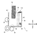
- a sliding bill press shutter 110 that slides a plurality of plate-like members in the front-rear direction is provided in the depositing unit 3. It may be.
- the bill press shutter 110 has a structure in which, for example, three rectangular plate-like members 111A, 111B, and 111C are connected in the vertical direction.
- the uppermost member 111A is referred to as a first member 111A
- the intermediate member 111B is referred to as a second member 111B
- the lowermost member 111C is referred to as a third member 111C.
- the first member 111A, the second member 111B, and the third member 111C each have an area of about 1/3 of the opening on the upper surface of the storage portion 3B. That is, the first member 111A, the second member 111B, and the third member 111C have three areas that can cover the entire opening of the upper surface of the storage portion 3B.
- the front end portion of the first member 111A is fixed to the upper end portion of the front wall of the storage portion 3B. Further, the second member 111B located below the first member 111A is connected to the first member 111A via a connecting portion 112A so as to be slidable in the front-rear direction.
- the third member 111C positioned below the second member 111B is connected to the second member 111B so as to be slidable in the front-rear direction via the connecting portion 112B.
- the upper end portion of the bill press 21 is located under the third member 111C, and the third member 111C can slide in the front-rear direction with respect to the upper end portion of the bill press 21 via the connecting portion 112C. It is connected.
- the bill press shutter 110 has such a configuration, and when the bill press 21 is actually positioned in the vicinity of the front wall of the storage portion 3B, the second member 111B and the second member 111B are below the first member 111A.
- the third member 111C is placed below and the bill press 21 is placed under the third member 111C so as to be layered and folded.
- the bill press shutter 110 causes the second member 111B and the third member 111C to slide rearward accordingly. Expand.
- the bill press shutter 110 is deployed so as to spread rearward from the state of being piled up and down as the bill press 21 is slid in the closing direction.
- the upper part of the internal mechanism area Ar2 between the front wall of 3B is always covered.
- connecting portions 112 (112A to 112C) may have any configuration as long as the members 111 (111A to 111C) can be slidably connected in the front-rear direction.
- the connecting portion 112A includes a front-rear direction groove (not shown) provided in the upper first member 111A and a protruding portion (provided on the upper surface of the lower second member 111B). (Not shown).
- the upper first member 111A and the lower second member are slidably fitted into the groove provided in the upper first member 111A by projecting the protrusion provided on the lower second member 111B.
- 111B is connected.
- the protrusion is formed in a T-shaped cross section so that it does not fall out of the groove.
- the other connecting portions 112B and 112C have the same configuration.
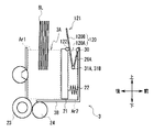
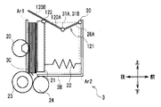
- the first member 26A is connected to the second member 120 that is longer in the front-rear direction (for example, about twice as long) than the first member 26A.
- a bill press shutter 121 may be provided.
- the second member 120 is divided into a front part 120A and a rear part 120B having the same size as the first member 26A.
- the second member 120 is longer than the first member 26A by the amount of the rear portion 120B.
- the front end portion of the front portion 120A is coupled to the rear end portion of the first member 26A via the coupling portions 31A and 31B. Further, in the second member, the boundary portion between the front portion 120A and the rear portion 120B is connected to the central portion at the upper end of the front surface of the bill press 21 via the connecting portion 122.
- the connecting portion 122 protrudes from the two plate-like bearing portions 123A and 123B protruding from the lower surface of the second member 120 and the front surface of the bill press 21.
- the two plate-like bearing portions 124A and 124B and the shaft 125 are provided.
- the bearing parts 123A, 123B, 124A, 124B are provided with circular shaft holes 126 penetrating in the left-right direction as holes through which the shaft 125 passes. ing.
- the bearings 124A and 124B provided in the bill press 21 are provided with elliptical shaft holes 127 penetrating in the left-right direction as holes through which the shaft 125 passes.
- the reason why the shaft hole 127 is elliptical is that the bill press 21 can be tilted, as in the first embodiment.
- the interval between the two bearing portions 124A and 124B provided on the bill press 21 side is wider than the interval between the two bearing portions 123A and 123B provided on the second member 120 side.
- the four bearing portions 123A and 124B provided on the bill press 21 side are positioned outside the two bearing portions 123A and 123B provided on the second member 120 side, respectively. , 123B, 124A, 124B, the shaft 125 is inserted into the shaft holes 126, 127, whereby the bill press 21 and the second member 120 are connected.
- the second member 120 is connected to the bill press 21 so as to be rotatable about a shaft 125 extending in the left-right direction as a rotation axis.
- the bill press shutter 121 has such a configuration, and when the bill press 21 is actually positioned in the vicinity of the front wall of the storage portion 3B, the front end of the first member 26A and the rear end of the second member 120 are brought closer to each other. Thus, it is in a folded state. At this time, the rear portion 120 ⁇ / b> B of the second member 120 projects upward from the upper end portion of the bill press 21.
- the bill press shutter 121 is developed so as to widen the V-shaped opening.
- the bill press shutter 121 expands backward from the folded state as the bill press 21 slides in the closing direction, and the bill press shutter 121 is in front of the bill press 21 and the storage unit 3B.
- the upper part of the internal mechanism area Ar2 between the wall and the wall is always covered.
- the portion protruding rearward from the bill press 21, that is, the rear portion 120B of the second member 120 covers the opening of the portion between the bill press 21 and the rear wall of the storage portion 3B, that is, the upper portion of the insertion port 3A. It will be.
- the bill press shutter 121 not only covers the internal mechanism area Ar2, but also when the bill press 21 presses the inserted bill against the pickup roller 20 to take in bills one by one.
- the inlet 3A can be covered so as to be taken in normally.
- the bill press shutter 121 can cover the insertion port 3A.
- a cover 128 may be provided at the front end portion of the upper end of the storage portion 3B so as to cover the rear portion 120B of the bill press shutter 121 that protrudes upward when folded. In this way, it is possible to prevent the rear portion 120B protruding upward from being damaged.
- the bill press shutter 25 that covers the internal mechanism area Ar ⁇ b> 2 between the bill press 21 and the front wall of the storage unit 3 ⁇ / b> B is provided in the depositing unit 3.
- the bill press shutter 25 may not be provided in the depositing unit 3 without being limited thereto. Even in this case, as shown in FIG. 16, when the bill press 21 is positioned at the standby slide position, the bill press 21 covers the intake 3 ⁇ / b> C, so that foreign matter enters the intake 3 ⁇ / b> C. Can be prevented.
- the thickness of the bill press 21 is set to a thickness that completely covers the upper portion of the intake port 3C when it is located at the standby slide position.
- the bill press shutter 21 may not be provided for the deposit / withdrawal unit 100 of the second embodiment.
- the bill press 21 is used as a specific example of the medium press unit, and the bill press shutters 25, 110, and 121 are used as specific examples of the shutter. As long as they function similarly, a medium press unit and a shutter having a mechanism different from those of the bill press 21 and the bill press shutters 25, 110, and 121 may be used.
- Embodiment 8 Furthermore, in 1st Embodiment mentioned above, although application to the banknote processing apparatus 1 as a staff operation type
- the present invention is not limited to the banknote processing apparatus 101 and can be applied to any apparatus having a mechanism that functions in the same manner as the deposit / withdrawal unit 100.
- banknote processing apparatus 1 which handles a banknote was illustrated, even if it is a medium processing apparatus which handles media other than a banknote, such as not only this but paper, a ticket. Any medium processing apparatus having a mechanism that functions in the same manner as the depositing unit 3 can be applied.
- the banknote processing apparatus 101 not only the banknote processing apparatus 101 but also a medium processing apparatus that handles media other than banknotes, such as paper and tickets, has a mechanism that functions in the same manner as the deposit and withdrawal unit 100.
- the present invention can be applied to any medium processing apparatus having the same.
- Embodiment 9 Furthermore, the embodiments are not limited to the first and second embodiments described above and the other embodiments described above. That is, the present invention is also applicable to an embodiment in which a part or all of the first and second embodiments described above and the other embodiments described above are arbitrarily combined, or an embodiment in which a part is extracted. The scope of application extends.
- the present invention can be widely used in apparatuses such as a banknote handling apparatus that handles banknotes.
Landscapes
- Physics & Mathematics (AREA)
- General Physics & Mathematics (AREA)
- Pile Receivers (AREA)
- Sheets, Magazines, And Separation Thereof (AREA)
Abstract
媒体処理装置は、媒体の投入口となる開口を有し、当該投入口から投入された媒体を収納する収納部と、前記収納部内の一端側の壁部と他端側の壁部との間を移動可能で、前記投入口から投入された媒体を、前記収納部の他端側の壁部に押し当てる媒体プレス部とを有する。前記投入口は、前記収納部の他端側の壁部と前記媒体プレス部との間の開口であり、前記投入口から投入された媒体は、前記収納部の他端側の壁部と前記媒体プレス部との間の媒体収納領域に収納され、媒体を前記投入口から投入させる媒体投入時には、前記媒体プレス部を、第1の位置に位置させ、待機時には、前記投入口の大きさが前記媒体投入時よりも狭くなるように、前記媒体プレス部を前記第1の位置よりも前記収納部内の他端側に位置する第2の位置に位置させる。
Description
本願は、2013年6月10日出願の日本国出願、特願2013-122133号の優先権を主張すると共に、その全体が参照により本明細書に取り込まれる。
本発明は、媒体処理装置に関し、例えば、媒体として紙幣を扱う紙幣処理装置に適用できるものである。
本発明は、媒体処理装置に関し、例えば、媒体として紙幣を扱う紙幣処理装置に適用できるものである。
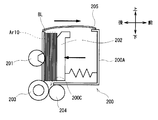
従来、紙幣処理装置には、図30に示すような入金部200が設けられている。この入金部200は、上面が開口している箱型の収納部200Aを有していて、この収納部200Aの開口の一部が紙幣の投入口200Bとなっている。
また収納部200Aの底には、その一端側(例えば後端側)に、収納部200A内に投入された紙幣の取込口200Cが設けられている。尚、ここで言う後端側とは、紙幣処理装置の正面から見て奥側のことである。
さらに、入金部200には、収納部200Aの後壁から一部が突出するようにしてピックアップローラ201が設けられている。
さらに、入金部200には、収納部200Aの後壁と平行な状態で、収納部200A内を前後方向にスライド可能な板状のビルプレス202が設けられている。このビルプレス202と収納部200Aの後壁との間の部分の開口が投入口200Bとなっている。
さらに、取込口200Cの下方近傍には、フィードローラ203とゲートローラ204とが前後方向に対向配置されている。
さらに、この入金部200の上側には、投入口200Bを露出させる方向及び覆う方向にスライド可能なシャッタ205が設けられている。
従来の紙幣処理装置は、このような入金部200を有していて、入金取引時、図31に示すように、シャッタ205を開けて入金部200の投入口200Bを露出させる。
尚、紙幣処理装置は、投入口200Bに紙幣を投入し易いように、シャッタ205を開ける前に、ビルプレス202を収納部200Aの前壁近傍の所定位置(これを入金開始スライド位置とも呼ぶ)に位置させ、投入口200Bを全開(もしくはほぼ全開)するようになっている。
ここで、図31に示すように、使用者が、投入口200Bから、ビルプレス202と収納部200Aの後壁との間の領域(これを紙幣収納領域とも呼ぶ)Ar10内に紙幣BLを投入したとする。
すると、紙幣処理装置は、図32に示すように、シャッタ205を閉じて入金部200の投入口200Bを覆い、ビルプレス202を収納部200Aの後壁へ近づける方向(この方向を、以下、閉方向と呼ぶ)にスライドさせる。
そして、紙幣処理装置は、紙幣BLをビルプレス202によってピックアップローラ201に押し付けると共に、ビルプレス202とピックアップローラ201との間で挟持する。
さらに、紙幣処理装置は、図33に示すように、ピックアップローラ201とフィードローラ203とを同期させて図中時計周りに回転させることにより、ピックアップローラ201に押し付けられた紙幣BLを下方の取込口200Cへと繰り出す。
このようにして取込口200Cへと繰り出された紙幣BLは、フィードローラ203とゲートローラ204により1枚ずつ分離され、取込口200Cから紙幣処理装置内へと取り込まれる。
紙幣処理装置は、このようにして入金部200に投入された紙幣BLを1枚ずつ取り込んでいくようになっている(例えば特開2011-8412公報参照)。
そして、図34に示すように、入金部200に投入された紙幣BLの全てを取り込み終えると、紙幣処理装置は、図35に示すように、シャッタ205を閉じたまま、ビルプレス202を再び入金開始スライド位置までスライドさせ、次の取引を待つ待機状態となる。
ところで、部品点数の削減及びコストの削減などの為、入金部200にシャッタ205を設けていない紙幣処理装置も存在する。
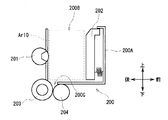
ここで、図36に、シャッタ205が無い入金部200を示す。この入金部200の場合、待機状態のときに、入金部200の投入口200Bを覆うものが無いため、投入口200Bが全開した状態で露出する。
このように、待機状態のときに、投入口200Bが全開した状態で露出していると、図37に示すように、投入口200Bから紙幣収納領域Ar10内へ硬貨などの異物210が進入してしまう恐れがある。
そして、実際に、図38に示すように、紙幣収納領域Ar10内に異物210が入りこんだまま、使用者がこのことに気付かずに、次の取引を行ってしまうと、異物210が取込口200Cからフィードローラ203とゲートローラ204の間に入り込んでしまう可能性がある。
この結果、入金部200に投入された紙幣の分離ができなかったり、フィードローラ203とゲートローラ204が破損したりするなどの装置異状を引き起こすことになる。
本発明は以上の点を考慮したもので、簡易な構成でありながら、装置異状を防止し得る媒体処理装置を提案しようとするものである。
本態様の媒体処理装置においては、媒体の投入口となる開口を有し、当該投入口から投入された媒体を収納する収納部と、収納部内の一端側の壁部と他端側の壁部との間を移動可能で、投入口から投入された媒体を、収納部の他端側の壁部に押し当てる媒体プレス部とを有し、投入口は、収納部の他端側の壁部と媒体プレス部との間の開口でなり、投入口から投入された媒体は、収納部の他端側の壁部と媒体プレス部との間の媒体収納領域に収納され、媒体を投入口から投入させる媒体投入時には、媒体プレス部を、第1の位置に位置させ、待機時には、投入口の大きさが媒体投入時よりも狭くなるように、媒体プレス部を第1の位置よりも収納部内の他端側に位置する第2の位置に位置させるようにした。
このように、待機時には、投入口の大きさが媒体投入時よりも狭くなるように媒体プレス部を位置させるようにした。こうすることで、投入口を覆うシャッタがなくとも、待機時に、投入口から収納部内への異物の進入を防ぐことができる。
本態様によれば、投入口を覆うシャッタがなくとも、待機時に、投入口から収納部内への異物の進入を防ぐことができ、かくして簡易な構成でありながら、異物の進入による装置異状を防止し得る媒体処理装置を実現できる。
以下、実施の形態について、図面を用いて詳細に説明する。
[1.第1の実施の形態]
[1-1.紙幣処理装置の外観構成]
まず第1の実施の形態について説明する。図1に、紙幣処理装置1の外観構成を示す。この紙幣処理装置1は、金融機関の職員(例えば受付窓口員)が操作する職員操作型端末であり、職員(ユーザ)の操作に基づいて紙幣の入出金処理を行う。
[1-1.紙幣処理装置の外観構成]
まず第1の実施の形態について説明する。図1に、紙幣処理装置1の外観構成を示す。この紙幣処理装置1は、金融機関の職員(例えば受付窓口員)が操作する職員操作型端末であり、職員(ユーザ)の操作に基づいて紙幣の入出金処理を行う。
尚、以下の説明では、紙幣処理装置1の正面から見て左側を紙幣処理装置1の左側、紙幣処理装置1の正面から見て右側を紙幣処理装置1の右側とする。
また、紙幣処理装置1の左側から右側への方向を右方向、紙幣処理装置1の右側から左側への方向を左方向、紙幣処理装置1の下側から上側への方向を上方向、紙幣処理装置1の上側から下側への方向を下方向、紙幣処理装置1の奥側から手前側への方向を前方向、紙幣処理装置1の手前側から奥側への方向を後ろ方向とする。
この紙幣処理装置1は、筐体2の上端部に、入金部3(図2参照)の投入口3A、出金部4(図2参照)の排出口4A、表示部5、及び操作部6が設けられている。
入金部3は、ユーザにより投入口3Aから入金紙幣が投入されると、これを1枚ずつ分離して紙幣処理装置1内に取り込んでいく。
出金部4は、出金紙幣を集積して、これを排出口4Aからユーザに取り出させるようになっている。
表示部5は、例えば液晶ディスプレイからなり、メニュー画面、各種処理の結果画面などを表示する。操作部6は、例えばボタンからなり、紙幣処理装置1に対する操作を受け付ける。
尚、紙幣処理装置1では、表示部5と操作部6とを別々に設けているが、例えばタッチパネル付き液晶ディスプレイなどを利用して、表示部5と操作部6とを一体に設けるようにしてもよい。
さらにこの紙幣処理装置1は、図示していないが、ネットワークを介して金融機関の端末やホストコンピュータと通信でき、端末やホストコンピュータとの間で各種情報を送受したり、端末側から操作したりできるようにもなっている。
[1-2.紙幣処理装置の内部構成]
次に、図2を用いて、紙幣処理装置1の内部構成について説明する。
次に、図2を用いて、紙幣処理装置1の内部構成について説明する。
紙幣処理装置1の筐体2内には、上述した入金部3、出金部4にくわえて、鑑別部10、一時保留部11、紙幣収納庫12A~12E、リジェクト庫13及び搬送路14が設けられている。
具体的には、筐体2内の上部に、入金部3が後側、出金部4が前側となるように、これら入金部3と出金部4とが前後方向に並べて設けられている。
また、出金部4の下方には、一時保留部11が設けられ、この一時保留部11より後方で、且つ入金部3の後方ななめ下には、鑑別部10が設けられている。
さらに、筐体2内の下部には、紙幣収納庫12A~12Eが前後方向に並べて設けられている。
さらに、一番手前側に位置する紙幣収納庫12Aの下には、リジェクト庫13が設けられている。
さらに、筐体2内には、これら入金部3、出金部4、鑑別部10、一時保留部11、紙幣収納庫12A~12E及びリジェクト庫13の各部を繋ぐ搬送路14が設けられている。
入金部3は、上面が開口している箱型の収納部3Bを有している。この収納部3Bの開口の一部が上述した投入口3Aとなる。この入金部3は、入金取引時に、ユーザによって投入口3Aから収納部3B内に投入された入金紙幣を1枚ずつ分離して紙幣処理装置1内に取り込んでいく。
また、この入金部3は、収納部3Bの底面がほぼ水平となる向きで紙幣処理装置1に固定されている。
出金部4は、上面が開口している箱型の集積部4Bを有している。この集積部4Bの開口が上述した排出口4Aとなる。この出金部4は、出金取引時に、紙幣収納庫12A~12Eなどから搬送されてくる出金紙幣を集積部4Bに集積して、ユーザに取り出させるようになっている。
また、この出金部4は、集積部4Bの前側が後側より下方に位置するよう前方に傾けられた状態で紙幣処理装置1に固定されている。
鑑別部10は、搬送路14を介して1枚ずつ搬送されてくる紙幣の金種、真偽、正損、走行状態などを鑑別するようになっている。そして、この鑑別部10は、その鑑別結果に基づいて、紙幣ごとに、取り扱うことのできる正常紙幣か取り扱うことのできないリジェクト紙幣かを判定する。
一時保留部11は、入金部3から取り込まれて鑑別部10により正常紙幣と判定された紙幣を一時的に集積する。このようにして一時保留部11に集積された紙幣は、取引成立後に、一時保留部11から繰り出されて鑑別部10に搬送され、鑑別部10により金種が特定された後、紙幣収納庫12A~12Eに搬送されて収納される。
尚、一時保留部11は、紙幣を順次重ねて集積する集積式であってもよいし、紙幣をドラムにテープと共に巻き付けて収納するドラム式であってもよい。
紙幣収納庫12A~12Eは、それぞれ、搬送路14を介して搬送されてくる紙幣を、内部に上下方向に重ねて集積する。また、紙幣収納庫12A~12Eは、紙幣を収納するだけでなく、内部に集積されている紙幣を1枚ずつ搬送路14に繰り出すことができる。
さらに、紙幣収納庫12A~12Eは、それぞれ個別に紙幣処理装置1から着脱可能となっている。
リジェクト庫13は、鑑別部10によってリジェクト紙幣と判定された紙幣を集積する。
またこの紙幣処理装置1の筐体2内には、所定箇所に、全体を制御する制御部(図示せず)が設けられている。
紙幣処理装置1は、以上の構成でなり、制御部が、鑑別部10による紙幣の鑑別結果などをもとに各部を制御して、紙幣の入金処理及び出金処理を行う。
すなわち、紙幣処理装置1は、入金取引時、ユーザにより、操作部6を介して取引項目(この場合、入金)などが入力され、さらに投入口3Aから入金部3に紙幣が投入されると、投入された紙幣を1枚ずつ鑑別部10に搬送する。
ここで、紙幣処理装置1は、鑑別部10により正常紙幣と判定された紙幣については一時保留部11に搬送して一時的に収納する。一方で、入金に適さない入金リジェクト紙幣と判定された紙幣については出金部4へ戻して、ユーザに返却する。
その後、ユーザにより入金金額が確定されると、一時保留部11に収納している紙幣を鑑別部10に搬送して金種を鑑別し、その金種に応じて、各紙幣収納庫12A~12Eへ搬送して保管する。
一方、出金取引時、紙幣処理装置1は、ユーザにより操作部6を介して、取引項目(この場合、出金)、出金金額などが入力されると、要求金額に応じて必要な金種毎の紙幣枚数を認識し、この金種毎の紙幣枚数に応じて各紙幣収納庫12A~12Eから紙幣を1枚ずつ繰り出して、鑑別部10に搬送する。
ここで、紙幣処理装置1は、鑑別部10により正常紙幣と判定された紙幣については出金部4に搬送する一方で、出金に適さない出金リジェクト紙幣と判定された紙幣については一時保留部11に搬送して一時的に収納する。
そして、出金部4に集積された出金金額分の紙幣を、ユーザが受け取る。
その後、紙幣処理装置1は、一時保留部11に収納している出金リジェクト紙幣を、リジェクト庫13へと搬送して保管する。
このようにして、紙幣処理装置1は、紙幣の入金処理及び出金処理を行う。
尚、一番手前側に位置する紙幣収納庫12Aと、その下に位置するリジェクト庫13は、別々に設けられていてもよいし、一体となっていてもよい。
紙幣収納庫12Aとリジェクト庫13が一体となっている場合、紙幣収納庫12Aを着脱するときに、紙幣収納庫12Aと共にリジェクト庫13も着脱される。
また、紙幣収納庫12Aについては、紙幣処理装置1に対する紙幣の補充及び回収を行う補充回収庫として利用するなどしてもよい。
[1-3.入金部の構成]
次に、入金部の構成について、詳しく説明する。
次に、入金部の構成について、詳しく説明する。
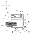
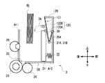
図3に示すように、入金部3は、上面が開口している箱型の収納部3Bを有している。この収納部3Bの底には、その一端側(例えば後端側)に、収納部3B内に投入された紙幣の取込口3Cが設けられている。
さらに入金部3には、収納部3Bの後壁から一部が突出するようにして、ピックアップローラ20が設けられている。
このピックアップローラ20の外周面には、当該外周面の全周の4分の1程度を覆う接触部材20Aが、当該外周面に沿って設けられている。この接触部材20Aは、ピックアップローラ20の外周面より摩擦係数の大きな部材(例えばゴムなど)となっている。
ピックアップローラ20は、詳しくは後述するが、この接触部材20Aを紙幣に接触させながら回転する。
また、ピックアップローラ20は、図4Bにも示すように、左右に1個ずつの計2個設けられていて、それぞれ、図示しないモータの駆動力により同期して回転するようになっている。
さらに、入金部3には、収納部3Bの後壁と平行な状態で、収納部3B内を前後方向にスライド可能な板状のビルプレス21が設けられている。
つまり、入金部3では、ビルプレス21を、収納部3Bの後壁へ近づける方向(閉方向)及び後壁から遠ざける方向(開方向)にスライドさせることができるようになっている。ビルプレス21は、図示しないモータの駆動力によりスライドする。
ここで、入金部3の上面に設けられた開口全体のうち、このビルプレス21と収納部3Bの後壁との間の部分の開口が、紙幣の投入口3Aとなっている。
また、この入金部3は、ビルプレス21と収納部3Bの後壁との間の領域が、投入口3Aから投入される紙幣を収納する紙幣収納領域Ar1となっていて、ビルプレス21と収納部3Bの前壁との間の領域が、ビルプレス21をスライドさせるバネなどの内部機構22が設けられた内部機構領域Ar2となっている。
さらに取込口3Cの下方近傍には、フィードローラ23とゲートローラ24とが前後方向に対向配置されている。
フィードローラ23は、図示しないモータの駆動力により、ピックアップローラ20と同期して回転する。
さらに、入金部3には、ビルプレス21と収納部3Bの前壁との間に、折り畳み式のビルプレスシャッタ25が設けられている。
このビルプレスシャッタ25は、ビルプレス21と収納部3Bの前壁との間の内部機構領域Ar2を覆うシャッタである。
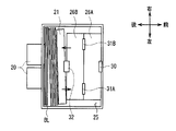
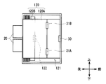
ビルプレスシャッタ25は、図4A及び図4Bに示すように、2枚の左右方向に長い長方形板状の部材26A及び26Bを前後方向に蝶番状に連結した構造となっている。尚、ここでは前側の部材26Aを第1部材26Aと呼び、後側の部材26Bを第2部材26Bと呼ぶ。
この第1部材26Aは、収納部3Bの上面の開口の前側半分と同程度の面積を有し、第2部材26Bは、開口の後側半分と同程度の面積を有している。すなわち、これら第1部材26A及び第2部材26Bは、2枚で、収納部3Bの上面の開口全体を覆うことができる程度の面積を有している。
第1部材26Aは、前端部の中央部分が、連結部30を介して収納部3Bの前壁の上端部分と連結されている。また第1部材26Aは、後端部の中央から所定間隔だけ左側にずれた箇所と右側にずれた箇所とが、それぞれ連結部31A及び31Bを介して第2部材26Bの前端部と連結されている。
一方、第2部材26Bは、前端部中央から所定間隔だけ左側にずれた箇所と、右側にずれた箇所とが、それぞれ連結部31A及び31Bを介して、第1部材26Aの後端部と連結されている。また第2部材26Bは、後端部の中央部分が、連結部32を介して、ビルプレス21の前面の上端中央部分と連結されている。
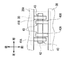
ここで、連結部30は、図5A及び図5Bに示すように、収納部3Bの前壁に突設された2つの板状の軸受部40A及び40Bと、第1部材26Aの前端部に突設された2つの板状の軸受部41A及び41Bと、シャフト42とで構成されている。
4つの軸受部40A、40B、41A、41Bのそれぞれには、シャフト42を通す孔として、左右方向に貫通する円形の軸孔43が設けられている。
また第1部材26A側に設けられた2つの軸受部41A及び41Bの間隔は、収納部3Bの前壁側に設けられた2つの軸受部40A及び40Bの間隔より広くなっている。
そして、第1部材26A側に設けられた2つの軸受部41A及び41Bが、それぞれ収納部3Bの前壁側に設けられた2つの軸受部40A及び40Bの外側に位置する状態で、これら4つの軸受部40A、40B、41A、41Bの軸孔43にシャフト42が挿入されることで、第1部材26Aと収納部3Bの前壁とが連結されている。
すなわち、第1部材26Aは、左右方向に延在するシャフト42を回転軸として回転自在に、収納部3Bの前壁と連結されている。
連結部31A及び31Bについても、連結部30と同様の構成であるので、説明を省略する。
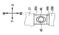
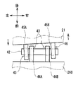
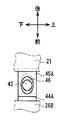
ビルプレス21と第2部材26Bとを連結する連結部32は、図6A及び図6Bに示すように、第2部材26Bの後端部に突設された2つの板状の軸受部44A及び44Bと、ビルプレス21の背面に突設された2つの板状の軸受部45A及び45Bと、シャフト42とで構成されている。
4つの軸受部44A、44B、45A、45Bのうち、第2部材26Bに設けられた軸受部44A、44Bには、シャフト42を通す孔として、左右方向に貫通する円形の軸孔43が設けられている。
これに対して、ビルプレス21に設けられた軸受部45A、45Bには、シャフト42を通す孔として、左右方向に貫通する楕円形の軸孔46が設けられている。この軸孔46が円形ではなく楕円形である点が、他の連結部30、31A及び31Bとは異なる点である。
またビルプレス21側に設けられた2つの軸受部45A及び45Bの間隔は、第2部材26B側に設けられた2つの軸受部44A及び44Bの間隔より広くなっている。
そして、ビルプレス21側に設けられた2つの軸受部45A及び45Bが、それぞれ第2部材26B側に設けられた2つの軸受部44A及び44Bの外側に位置する状態で、これら4つの軸受部44A、44B、45A、45Bの軸孔43、46にシャフト42が挿入されることで、ビルプレス21と第2部材26Bとが連結されている。
すなわち、第2部材26Bは、左右方向に延在するシャフト42を回転軸として回転自在に、ビルプレス21と連結されている。
ここで、シャフト42の断面が円形であるのに対して、ビルプレス21側の2つの軸受部45A及び45Bのそれぞれに設けられた軸孔46は、シャフト42の断面より大きな、前後方向に長い楕円形となっている。
すなわち、ビルプレス21側の2つの軸受部45A及び45Bのそれぞれに設けられた軸孔46には、シャフト42が回転するだけでなく、前後方向にずれることができるように遊びが設けられている。
これにより、ビルプレス21は、収納部3Bの後壁の壁面と平行な状態から、左端を後方にずらすと共に右端を前方にずらすように、またはその逆に姿勢を傾けることができるようになっている。
ビルプレスシャッタ25は、このような構成でなり、図3に示すように、ビルプレス21が収納部3Bの前壁近傍に位置しているときには、第1部材26Aの前端と第2部材26Bの後端とを近づけるように閉じて折り畳まれた状態となっている。
このとき、第1部材26Aと第2部材26Bとを連結する連結部31A及び31Bは、連結部30及び32より下方に位置する。つまり、ビルプレスシャッタ25は、V字型に折り畳まれた状態となっている。
この状態から、ビルプレス21が閉方向(後方)にスライドしていくと、図4Aに示すように、ビルプレスシャッタ25は、第1部材26Aの前端と第2部材26Bの後端とを遠ざけるように開いて展開していく。
すなわち、ビルプレスシャッタ25は、V字の開きを大きくするようにして展開していく。
このように、ビルプレスシャッタ25は、ビルプレス21の閉方向へのスライドにともなって、折り畳まれた状態から展開していき、ビルプレス21と収納部3Bの前壁との間の内部機構領域Ar2の上部を常に覆うようになっている。
[1-4.入金取引時の入金部の動作]
次に、実際に、紙幣を入金するときの入金部3の動作について説明する。入金部3は、入金取引を行うとき以外は、待機状態となっている。
次に、実際に、紙幣を入金するときの入金部3の動作について説明する。入金部3は、入金取引を行うとき以外は、待機状態となっている。
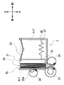
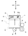
待機状態の入金部3は、図7に示すように、ビルプレス21をピックアップローラ20に押し付けて接触させた状態となっている。このときのビルプレス21の位置を、第2の位置としての待機スライド位置とする。
ビルプレス21が待機スライド位置にあるとき、ビルプレス21と収納部3Bの後壁との間の開口である投入口3Aは、最も狭くなる。実際、入金部3では、このときの投入口3Aが、異物として想定される硬貨(例えば10円硬貨)の厚みよりも狭く、ほぼ閉じた状態となっている。
また、このとき、紙幣収納領域Ar1も、最も狭くなる。こうすることで、紙幣処理装置1は、入金部3が待機状態のときに、入金部3の投入口3Aから紙幣収納領域Ar1内に硬貨などの異物が進入することを防ぐことができる。
また、この待機状態のとき、入金部3のビルプレス21と収納部3Bの前壁との間の内部機構領域Ar2は、その上部が、展開されたビルプレスシャッタ25により覆われる。
これにより、紙幣処理装置1は、入金部3が待機状態のときに、入金部3の内部機構領域Ar2内に異物が進入することを防ぐこともできる。
ここで、ユーザにより、操作部6を介して入金取引の実行が選択されたとする。
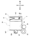
すると、紙幣処理装置1は、図8に示すように、ビルプレス21を、待機スライド位置から開方向(前方)にスライドさせ、収納部3Bの前壁近傍の所定位置で停止させる。このときビルプレス21を停止させた位置を、第1の位置としての入金開始スライド位置とする。
このとき、ビルプレス21と収納部3Bの後壁との間の開口である投入口3Aは徐々に広がっていき、ビルプレス21が入金開始スライド位置に到達したときに最も広くなり、全開した状態となる。
このように、紙幣処理装置1は、入金取引で紙幣を投入させるときには、紙幣を投入し易いように、投入口3Aを全開する。また、紙幣処理装置1は、このように、投入口3Aを全開することにより、この投入口3Aから紙幣を投入すればよい旨を、ユーザに容易且つ確実に認識させることもできる。
尚、ここでは、投入口3Aを全開したが、必ずしも全開にする必要はなく、要は、紙幣を投入し易いように、できるだけ投入口3Aを広くすればよい。
その後、図9に示すように、ユーザが投入口3Aから紙幣BLを投入すると、紙幣処理装置1は、図示しないセンサにより、投入口3Aから紙幣収納領域Ar1に紙幣BLが投入されたことを認識する。
すると、紙幣処理装置1は、入金開始スライド位置にあるビルプレス21を閉方向にスライドさせる。
このとき、ビルプレスシャッタ25が内部機構領域Ar2の上部を覆いながら展開していくことで、内部機構領域Ar2は、このビルプレスシャッタ25により常に塞がれた状態となる。
これにより、ユーザが、内部機構領域Ar2内に誤って紙幣を投入したり、この内部機構領域Ar2内に、異物が進入したりすることを防ぐことができる。
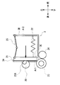
そして、図10に示すように、紙幣処理装置1は、紙幣収納領域Ar1に投入された紙幣BLをビルプレス21によってピックアップローラ20に押し付けると共に、ビルプレス21とピックアップローラ20との間で挟持する。
ここで、ビルプレス21は、上述したように、収納部3Bの後壁の壁面に対して傾くことができるようになっている。これにより、ビルプレス21は、例えば、図11A~図11Cに示すように、投入される紙幣の種類や状態の違いによって、紙幣束の厚みに左右で差が生じるような場合でも、その差に応じて姿勢を傾けることができるので、紙幣の束をより確実にピックアップローラ20との間で挟持することができる。
また、図10に示すように、ピックアップローラ20は、前もって、待機状態のときに、入金取引で紙幣の取り込みを開始するときに最適な回転位置(これを、以下、取込開始回転位置と呼ぶ)に回転させられていて、この取込開始回転位置で停止している。
取込開始回転位置は、接触部材20Aの周方向の一端がピックアップローラ20と紙幣BLとの接触箇所に位置すると共に、周方向の他端が一端より上側に位置するように、ピックアップローラ20を回転させたときの回転位置である。
尚、ここで言う周方向の一端とは、接触部材20Aをピックアップローラ20と共に図中時計回りに回転させるときの、回転方向から見て先に位置する端(これを先端と呼ぶ)であり、周方向の他端とは、回転方向から見て後に位置する端(これを後端と呼ぶ)である。
ゆえに、紙幣収納領域Ar1に投入された紙幣BLを、取込開始回転位置で停止しているピックアップローラ20に押し付けると、ピックアップローラ20の接触部材20Aの先端と、投入された紙幣BLのうちの一番奥の紙幣BLが接触する。
そして、図12に示すように、紙幣処理装置1は、取込開始回転位置で停止しているピックアップローラ20を、図中時計周りに回転させると共に、このピックアップローラ20の回転と同期させて、フィードローラ23を回転させる。
このとき、ピックアップローラ20は、接触部材20Aの先端から後端までを、紙幣収納領域Ar1内に投入された一番奥の1枚の紙幣BLに接触させていきながら回転することになる。
これにより、一番奥の1枚の紙幣BLが、接触部材20Aとの摩擦によって、下方の取込口3Cへと繰り出される。
そして、取込口3Cへと繰り出された紙幣BLは、フィードローラ23とゲートローラ24により他の紙幣BLから分離され、取込口3Cから紙幣処理装置1内へと取り込まれる。
このように、紙幣処理装置1は、入金取引時に、入金部3のピックアップローラ20を、取込開始回転位置から回転させ、接触部材20Aの先端から後端までを、一番奥の紙幣BLに接触させていくことにより、一番奥の紙幣BLを1枚ずつ確実に分離して取り込んでいくことができる。
紙幣処理装置1は、その後も、ピックアップローラ20とフィードローラ23とを回転し続けることにより、1枚目の紙幣BLと同様にして、紙幣収納領域Ar1内に投入された紙幣BLを1枚ずつ取り込んでいく。
そして、紙幣処理装置1は、図13に示すように、入金部3に投入された紙幣BLの全てを取り込み終えると、このことを、図示しないセンサにより認識する。
すると、紙幣処理装置1は、図14に示すように、ビルプレス21を、開方向(前方)にスライドさせ、所定位置で停止させる。このときビルプレス21を停止させた位置を、第3の位置としての退避スライド位置とする。
この退避スライド位置は、ビルプレス21とピックアップローラ20及び接触部材20Aとが接触しない位置であればどこでもよく、入金開始スライド位置と同じ位置でもよいし、入金開始スライド位置よりも収納部3Bの後壁に近い位置であってもよい。
このようにして、ビルプレス21を、退避スライド位置に移動させた後、紙幣処理装置1は、図15に示すように、次の取引にそなえて、ピックアップローラ20を、取込開始回転位置まで回転させて停止させる。
このように、紙幣処理装置1は、ビルプレス21をピックアップローラ20及び接触部材20Aから離した後に、ピックアップローラ20を取込開始回転位置まで回転させる。
このようにする理由は、ピックアップローラ20又は接触部材20Aにビルプレス21が接触したままの状態でピックアップローラ20を回転させると、ビルプレス21からの押圧力が影響して、ピックアップローラ20を正確に取込開始回転位置に合わせることが難しいからである。
換言すれば、紙幣処理装置1は、ビルプレス21をピックアップローラ20及び接触部材20Aから離したうえで、ピックアップローラ20を回転させることにより、ピックアップローラ20を、正確に取込開始回転位置に合わせることができる。
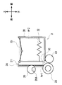
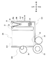
その後、紙幣処理装置1は、図16に示すように、再び、ビルプレス21を閉方向にスライドさせてピックアップローラ20に押し付け(つまり、ビルプレス21を待機スライド位置に位置させ)、入金部3を待機状態とする。
以上の動作が、入金取引時の入金部3の動作である。
[1-5.効果]
上述したように、紙幣処理装置1は、入金部3が待機状態のとき(すなわち待機時)には、ビルプレス21を待機スライド位置に位置させてピックアップローラ20に押し付けることにより、投入口3Aがほぼ閉じるように、投入口3Aを狭くする。
上述したように、紙幣処理装置1は、入金部3が待機状態のとき(すなわち待機時)には、ビルプレス21を待機スライド位置に位置させてピックアップローラ20に押し付けることにより、投入口3Aがほぼ閉じるように、投入口3Aを狭くする。
その後、紙幣処理装置1は、入金取引で紙幣を投入させるときに、ビルプレス21を待機スライド位置から開方向にスライドさせることにより、投入口3Aを広げる。
つまり、紙幣処理装置1は、入金取引で紙幣を投入させるときには、紙幣を投入し易くする為に、投入口3Aを広げる一方で、待機時には、異物の進入を防ぐ為に、入金取引での紙幣投入時よりも投入口3Aを狭くする。
こうすることで、紙幣処理装置1は、入金取引を行っていない待機時に、入金部3の投入口3Aから紙幣収納領域Ar1内に異物が進入することを防ぐことができる。
また、紙幣処理装置1は、ビルプレス21と収納部3Bの前壁との間の内部機構領域Ar2の上部に、ビルプレス21が閉方向にスライドすることにともなって内部機構領域Ar2を覆うように展開されるビルプレスシャッタ25を設けるようにした。
これにより、紙幣処理装置1は、待機時に、内部機構領域Ar2内に異物が進入することを防ぐこともできる。
さらに、紙幣処理装置1は、待機時に、次の入金取引にそなえて、前もって、ピックアップローラ20を、入金取引で紙幣の取り込みを開始するときに最適な取込開始回転位置に合わせておくようにした。
これにより、紙幣処理装置1は、入金取引で紙幣の取り込みを行うときに、ピックアップローラ20を取込開始回転位置に合わせる動作を行う必要がなくなり、その分、入金取引の動作を簡略化することができると共に、入金取引にかかる時間を短くすることができる。
さらに、紙幣処理装置1は、入金部3が待機状態となるときに、ビルプレス21を一旦、退避スライド位置までスライドさせてピックアップローラ20から離した状態で、ピックアップローラ20を取込開始回転位置に合わせるようにした。
これにより、紙幣処理装置1は、ピックアップローラ20を正確に取込開始回転位置に合わせることができる。
以上の構成によれば、紙幣処理装置1は、投入口3Aを覆うシャッタがなくとも、待機時に、投入口3Aから入金部3の収納部3B内に異物が進入することを防ぐことがでる。
これにより、紙幣処理装置1は、異物が収納部3Bの取込口3Cからフィードローラ203とゲートローラ204の間に入り込んでしまうことを防いで装置異状を引き起こす状況を回避することができる。
かくして、紙幣処理装置1は、簡易な構成でありながら、異物の進入による装置異状を防止することができる。
[2.第2の実施の形態]
次に第2の実施の形態について説明する。この第2の実施の形態は、図17に示すように、入金部3と出金部4の代わりに、入金部3と出金部4の両方の機能を兼ね備えた入出金部100を有する紙幣処理装置101への適用例である。
次に第2の実施の形態について説明する。この第2の実施の形態は、図17に示すように、入金部3と出金部4の代わりに、入金部3と出金部4の両方の機能を兼ね備えた入出金部100を有する紙幣処理装置101への適用例である。
尚、図2と図17とを比較すれば明らかなように、紙幣処理装置101の入出金部100以外の構成は、第1の実施の形態の紙幣処理装置1と同一であるので、詳しい説明は省略する。
また、図18に示すように、入出金部100の構成については、入金部3と同一であるので、詳しい説明は省略する。
尚、入出金部100は、図17に示すように、収納部3Bの前側が後側より下方に位置するよう前方に傾けられた状態で紙幣処理装置101に固定されているが、これに限らず、収納部3Bの底面がほぼ水平となる向きで紙幣処理装置101に固定されていてもよい。
さらに、入出金部100の入金取引時の動作については、入金部3と同一であるので、詳しい説明は省略する。
ゆえに、ここでは、入出金部100の出金取引時の動作についてのみ説明する。
尚、入出金部100の投入口3Aは、入金取引時には、ユーザが紙幣を投入する投入口として機能する一方で、出金取引時には、ユーザに紙幣を取り出させる為の排出口として機能する。ゆえに、出金取引の説明では、投入口3Aを排出口3Aと呼ぶ。
また、入出金部100の収納部3Bは、入金取引時には、ユーザが投入した紙幣を収納する収納部として機能する一方で、出金取引時には、ユーザに取り出させる紙幣を集積する集積部として機能する。ゆえに、出金取引の説明では、収納部3Bを集積部3Bと呼ぶ。
さらに、入出金部100の取込口3Cは、入金取引時には、ユーザが投入した紙幣を紙幣処理装置101内へと取り込む取込口として機能する一方で、出金取引時には、紙幣処理装置101内から紙幣収納領域Ar1へと紙幣を繰り出す繰出口として機能する。ゆえに、出金取引の説明では、取込口3Cを繰出口3Cと呼ぶ。
[2-1.出金取引時の入出金部の動作]
入出金部100は、入金取引及び出金取引を行うとき以外は、待機状態となっている。
入出金部100は、入金取引及び出金取引を行うとき以外は、待機状態となっている。
待機状態の入出金部100は、図19に示すように、ビルプレス21をピックアップローラ20に押し付けた状態(すなわち待機スライド位置に位置させた状態)となっている。
このとき、ビルプレス21と集積部3Bの後壁との間の開口である排出口3Aは、最も狭くなる。実際、入出金部100では、このときの排出口3Aが、異物として想定される硬貨(例えば10円硬貨)の厚みよりも狭く、ほぼ閉じた状態となっている。
また、このとき、紙幣収納領域Ar1も、最も狭くなる。こうすることで、紙幣処理装置101は、入出金部100が待機状態のときに、入出金部100の排出口3Aから紙幣収納領域Ar1内に硬貨などの異物が進入することを防ぐことができる。
また、この待機状態のとき、入出金部100のビルプレス21と集積部3Bの前壁との間の内部機構領域Ar2は、その上部が、展開されたビルプレスシャッタ25により覆われる。
これにより、紙幣処理装置101は、入出金部100が待機状態のときに、入出金部100の内部機構領域Ar2内に異物が進入することを防ぐこともできる。
ここで、ユーザにより、操作部6を介して出金取引の実行が選択されたとする。
すると、紙幣処理装置101は、図20に示すように、ビルプレス21を、開方向(前方)にスライドさせ、収納部3Bの後壁と前壁との間の所定位置で停止させる。このときビルプレス21を停止させた位置を、出金開始スライド位置とする。
尚、この出金開始スライド位置は、紙幣収納領域Ar1が広くなりすぎないように、入金開始スライド位置(図8参照)よりも集積部3Bの後壁に近い位置となっている。
紙幣処理装置101は、ビルプレス21が出金開始スライド位置に到達したことを図示しないセンサにより認識すると、ピックアップローラ20を、入金取引時とは逆方向(図中反時計周り)に回転させると共に、このピックアップローラ20の回転と同期させて、フィードローラ23を回転させる。
これにより、繰出口3Cから紙幣収納領域Ar1内へと、紙幣BLが1枚ずつ繰り出されていく。
ここで、紙幣処理装置101は、図21に示すように、紙幣収納領域Ar1内へと1枚ずつ紙幣BLを繰り出していくときに、1番奥の紙幣BL(すなわち直近に繰り出された紙幣BLであり図中左端の紙幣BL)の位置が常に同じ位置となるように、紙幣収納領域Ar1内に繰り出された紙幣BLの枚数が増えるにつれて、ビルプレス21を開方向に少しずつスライドさせていく。
そして、紙幣処理装置101は、出金金額分の紙幣BLを紙幣収納領域Ar1内に繰り出し終えると、紙幣を取り出し易いように、ビルプレス21を入金開始スライド位置と同じ位置まで開方向にスライドさせて停止させる。このとき排出口3Aは全開となる。このときビルプレス21を停止させた位置を、第4の位置としての出金終了スライド位置とする。
尚、ここでは、排出口3Aを全開したが、必ずしも全開にする必要はなく、要は、紙幣を取り出し易いように、できるだけ排出口3Aを広くすればよい。
その後、図22に示すように、ユーザが排出口3Aから紙幣を全て取り出すと、紙幣処理装置101は、図示しないセンサにより、入出金部100の紙幣収納領域Ar1内に繰り出した紙幣BLの全てが取り出されたことを認識する。
すると、紙幣処理装置101は、図23に示すように、次の取引にそなえて、ピックアップローラ20を、取込開始回転位置まで回転させて停止させる。
尚、次の取引が入金取引と出金取引のどちらであるかを予測することは困難であり、また、出金取引を開始するときのピックアップローラ20の回転位置は任意の位置でよいことから、ここでは、ピックアップローラ20を取込開始回転位置に位置合わせする。
その後、紙幣処理装置101は、図24に示すように、再び、ビルプレス21を閉方向にスライドさせてピックアップローラ20に押し付け(つまり、ビルプレス21を待機スライド位置に位置させ)、入出金部100を待機状態とする。
以上の動作が、出金取引時の入出金部100の動作である。
[2-2.効果]
上述したように、紙幣処理装置101は、入出金部100が待機状態のとき(すなわち待機時)には、ビルプレス21を待機スライド位置に位置させて集積部3Bの後壁から突出しているピックアップローラ20に押し付けることで、排出口(投入口)3Aがほぼ閉じた状態となるように、排出口(投入口)3Aを狭くする。
上述したように、紙幣処理装置101は、入出金部100が待機状態のとき(すなわち待機時)には、ビルプレス21を待機スライド位置に位置させて集積部3Bの後壁から突出しているピックアップローラ20に押し付けることで、排出口(投入口)3Aがほぼ閉じた状態となるように、排出口(投入口)3Aを狭くする。
その後、紙幣処理装置101は、出金取引で紙幣を取り出させるとき又は入金取引で紙幣を投入させるときには、ビルプレス21を開方向にスライドさせて、排出口(投入口)3Aを広げる。
つまり、紙幣処理装置1は、出金取引での紙幣取出時及び入金取引での紙幣投入時には、紙幣を取り出し易くする及び投入し易くする為に、排出口(投入口)3Aを広げる一方で、待機時には、異物の進入を防ぐ為に、紙幣取出時及び紙幣投入時よりも排出口(投入口)3Aを狭くする。
こうすることで、紙幣処理装置101は、出金取引及び入金取引を行っていない待機時に、入出金部100の排出口(投入口)3Aから紙幣収納領域Ar1内に異物が進入することを防ぐことができる。
また、紙幣処理装置101は、待機時に、次の入金取引にそなえて、前もって、ピックアップローラ20を、入金取引を開始するときに最適な取込開始回転位置に合わせておくようにした。
これにより、紙幣処理装置101は、入金取引を行うときに、ピックアップローラ20を取込開始回転位置に合わせる動作を行う必要がなくなり、その分、入金取引の動作を簡略化することができると共に、入金取引にかかる時間を短くすることができる。
以上の構成によれば、紙幣処理装置101は、排出口(投入口)3Aを覆うシャッタがなくとも、待機時に、排出口(投入口)3Aから入出金部100の集積部(収納部)3B内に異物が進入することを防ぐことができる。
これにより、紙幣処理装置101は、異物が集積部(収納部)3Bの繰出口(取込口)3Cからフィードローラ203とゲートローラ204の間に入り込んでしまうことを防いで装置異状を引き起こす状況を回避することができる。
かくして、紙幣処理装置101は、簡易な構成でありながら、異物の進入による装置異状を防止することができる。
ここまで説明したように、この第2の実施の形態では、入金部3と出金部4の両方の機能を兼ね備えた入出金部100を有する紙幣処理装置101が、入金取引及び出金取引が完了して待機状態となるときに、入出金部100の排出口(投入口)3Aを、紙幣投入時及び紙幣取出時よりも狭くするようにした。
こうすることで、入出金部100を有する紙幣処理装置101でも、入金部3を有する紙幣処理装置1と同様の効果を得ることができる。
[3.他の実施の形態]
[3-1.他の実施の形態1]
尚、上述した第1の実施の形態では、入金部3が待機状態のとき(すなわち待機時)に、ビルプレス21をピックアップローラ20に押し付けることで、投入口3Aを入金取引での紙幣投入時よりも狭くするようにした。
[3-1.他の実施の形態1]
尚、上述した第1の実施の形態では、入金部3が待機状態のとき(すなわち待機時)に、ビルプレス21をピックアップローラ20に押し付けることで、投入口3Aを入金取引での紙幣投入時よりも狭くするようにした。
これに限らず、待機時に、投入口3Aが入金取引での紙幣投入時よりも狭くなるように、ビルプレス21をピックアップローラ20に押し付けるのではなく、ビルプレス21をピックアップローラ20に近接させる(すなわち収納部3Bの後壁に近接させる)だけでもよい。
この場合でも、投入口3Aの大きさが、想定される異物(例えば硬貨)が進入できない程度まで狭くなっていれば、投入口3Aから紙幣収納領域Ar1内に異物が進入することを十分防ぐことができる。
第2の実施の形態の入出金部100についても同様に、待機時に、排出口(投入口)3Aが入金取引での紙幣投入時及び出金取引での紙幣取出時よりも狭くなるように、ビルプレス21をピックアップローラ20に近接させるだけでもよい。
[3-2.他の実施の形態2]
また、上述した第1の実施の形態では、入金部3に投入された紙幣BLの全てを取り込み終えると、ビルプレス21を退避スライド位置に移動させ、ビルプレス21が退避スライド位置に到達したら、ピックアップローラ20を回転させて取込開始回転位置に合わせるようにした。
また、上述した第1の実施の形態では、入金部3に投入された紙幣BLの全てを取り込み終えると、ビルプレス21を退避スライド位置に移動させ、ビルプレス21が退避スライド位置に到達したら、ピックアップローラ20を回転させて取込開始回転位置に合わせるようにした。
これに限らず、ビルプレス21を退避スライド位置に移動させるときに、ビルプレス21がピックアップローラ20から離れた時点で、ピックアップローラ20を回転させて取込開始回転位置に合わせるようにしてもよい。
このように、ビルプレス21の退避スライド位置への移動と、ピックアップローラ20の位置合わせとを、並行して行うようにすれば、ビルプレス21の移動を開始してから、ピックアップローラ20の位置合わせが完了するまでの時間を短縮できる。
[3-3.他の実施の形態3]
さらに、上述した第1の実施の形態では、ピックアップローラ20の外周面に、当該外周面の全周の4分の1程度を覆う接触部材20Aを、当該外周面に沿って設けるようにした。
さらに、上述した第1の実施の形態では、ピックアップローラ20の外周面に、当該外周面の全周の4分の1程度を覆う接触部材20Aを、当該外周面に沿って設けるようにした。
これに限らず、接触部材20Aについては、例えば、全周の2分の1程度を覆うものであってもよいし、全周を覆うものであってもよい。
第2の実施の形態の入出金部100についても同様に、接触部材20Aについては、例えば、全周の2分の1程度を覆うものであってもよいし、全周を覆うものであってもよい。
[3-4.他の実施の形態4]
さらに、上述した第1の実施の形態では、入金部3と出金部4を有する紙幣処理装置1への適用例を説明した。また、上述した第2の実施の形態では、入金部3と出金部4の両方の機能を兼ね備えた入出金部100を有する紙幣処理装置101への適用例を説明した。
さらに、上述した第1の実施の形態では、入金部3と出金部4を有する紙幣処理装置1への適用例を説明した。また、上述した第2の実施の形態では、入金部3と出金部4の両方の機能を兼ね備えた入出金部100を有する紙幣処理装置101への適用例を説明した。
これに限らず、入出金部を複数有する紙幣処理装置や、入出金部と入金部又は出金部とを有する紙幣処理装置などに適用してもよく、このような紙幣処理装置に適用した場合も、入金部や入出金部への異物の進入による装置異状を防止することができる。
[3-5.他の実施の形態5]
さらに、上述した第1の実施の形態では、入金部3に、板状の第1部材26Aと第2部材26Bとを連結した折り畳み式のビルプレスシャッタ25を設けるようにした。
さらに、上述した第1の実施の形態では、入金部3に、板状の第1部材26Aと第2部材26Bとを連結した折り畳み式のビルプレスシャッタ25を設けるようにした。
これに限らず、ビルプレスシャッタ25と同様に機能するものであれば、ビルプレスシャッタ25とは異なるシャッタを用いるようにしてもよい。
例えば、図25A及び図25Bに示すように、入金部3に、折り畳み式のビルプレスシャッタ25の変わりに、複数枚の板状部材を前後方向にスライドさせるスライド式のビルプレスシャッタ110を設けるようにしてもよい。
このビルプレスシャッタ110は、例えば、3枚の長方形板状の部材111A、111B、111Cを上下方向に連結した構造となっている。尚、ここでは一番上の部材111Aを第1部材111A、中間の部材111Bを第2部材111B、一番下の部材111Cを第3部材111Cと呼ぶ。
これら第1部材111A、第2部材111B、第3部材111Cは、それぞれ、収納部3Bの上面の開口の1/3程度の面積を有している。すなわち、これら第1部材111A、第2部材111B、第3部材111Cは、3枚で、収納部3Bの上面の開口全体を覆うことができる程度の面積を有している。
第1部材111Aは、その前端部が、収納部3Bの前壁の上端部分に固定されている。またこの第1部材111Aの下に位置する第2部材111Bは、第1部材111Aに対して、連結部112Aを介して前後方向にスライド可能に連結されている。
またこの第2部材111Bの下に位置する第3部材111Cは、第2部材111Bに対して、連結部112Bを介して前後方向にスライド可能に連結されている。
さらにこの第3部材111Cの下に、ビルプレス21の上端部が位置していて、第3部材111Cは、ビルプレス21の上端部に対して、連結部112Cを介して前後方向にスライド可能に連結されている。
ビルプレスシャッタ110は、このような構成でなり、実際、ビルプレス21が収納部3Bの前壁近傍に位置しているときには、第1部材111Aの下に第2部材111B、第2部材111Bの下に第3部材111C、第3部材111Cの下にビルプレス21が位置するように層状に重ねられて畳まれた状態となっている。
この状態から、ビルプレス21が閉方向(後方)にスライドしていくと、ビルプレスシャッタ110は、これに合わせて、第2部材111Bと第3部材111Cのそれぞれが後方にスライドするようにして展開していく。
このように、ビルプレスシャッタ110は、ビルプレス21の閉方向へのスライドにともなって、上下に重ねられて畳まれた状態から、後方に広がるように展開していき、ビルプレス21と収納部3Bの前壁との間の内部機構領域Ar2の上部を常に覆うようになっている。
これにより、ユーザが、内部機構領域Ar2内に誤って紙幣を投入したり、この内部機構領域Ar2内に、紙幣以外の異物を投入したりすることを防ぐことができる。
尚、各連結部112(112A~112C)については、各部材111(111A~111C)を前後方向にスライド自在に連結できる構成であればどのような構成であってもよい。
具体的な例としては、連結部112Aを、上側の第1部材111Aに設けられた前後方向の溝(図示せず)と、下側の第2部材111Bの上面に突設された突起部(図示せず)とで構成する。
そして、下側の第2部材111Bに設けられた突起部を上側の第1部材111Aに設けられた溝にスライド自在に嵌合することで、上側の第1部材111Aと下側の第2部材111Bとを連結するようにする。また、この場合、突起部を断面T字型に形成するなどして、溝から抜け落ちないようにする。他の連結部112B、112Cについても、同様の構成とする。
尚、このようなビルプレスシャッタ110を、第2の実施の形態の入出金部100に設けるようにしてもよい。
また、例えば、図26A、図26B及び図27に示すように、第1部材26Aと、この第1部材26Aより前後方向に長い(例えば2倍程度長い)第2部材120とを連結してなるビルプレスシャッタ121を設けるようにしてもよい。
尚、ここでは、説明を簡単にする為、第2部材120を、第1部材26Aと同サイズの前部120Aと、後部120Bとに分けている。
すなわち、第2部材120は、後部120Bの分だけ、第1部材26Aより長くなっている。
この第2部材120は、前部120Aの前端部分が、連結部31A及び31Bを介して、第1部材26Aの後端部と連結されている。またこの第2部材は、前部120Aと後部120Bとの境界部分が、連結部122を介して、ビルプレス21の前面の上端中央部分と連結されている。
ここで、連結部122は、例えば、図28A及び図28Bに示すように、第2部材120の下面に突設された2つの板状の軸受部123A及び123Bと、ビルプレス21の前面に突設された2つの板状の軸受部124A及び124Bと、シャフト125とで構成されている。
4つの軸受部123A、123B、124A、124Bのうち、第2部材120に設けられた軸受部123A、123Bには、シャフト125を通す孔として、左右方向に貫通する円形の軸孔126が設けられている。
これに対して、ビルプレス21に設けられた軸受部124A、124Bには、シャフト125を通す孔として、左右方向に貫通する楕円形の軸孔127が設けられている。軸孔127を楕円形とした理由は、第1の実施の形態と同様、ビルプレス21を傾けることができるようにするためである。
またビルプレス21側に設けられた2つの軸受部124A及び124Bの間隔は、第2部材120側に設けられた2つの軸受部123A及び123Bの間隔より広くなっている。
そして、ビルプレス21側に設けられた2つの軸受部124A及び124Bが、それぞれ第2部材120側に設けられた2つの軸受部123A及び123Bの外側に位置する状態で、これら4つの軸受部123A、123B、124A、124Bの軸孔126、127にシャフト125が挿入されることで、ビルプレス21と第2部材120とが連結されている。
すなわち、第2部材120は、左右方向に延在するシャフト125を回転軸として回転自在に、ビルプレス21と連結されている。
ビルプレスシャッタ121は、このような構成でなり、実際、ビルプレス21が収納部3Bの前壁近傍に位置しているときには、第1部材26Aの前端と第2部材120の後端とを近づけるようにして折り畳まれた状態となっている。このとき、第2部材120の後部120Bが、ビルプレス21の上端部より上方に突出するようになっている。
この状態から、ビルプレス21が閉方向(後方)にスライドしていくと、ビルプレスシャッタ121は、第1部材26Aの前端と第2部材120の後端とを遠ざけるようにして展開していく。
このとき、ビルプレスシャッタ121は、V字の開きを大きくするようにして展開していく。
このように、ビルプレスシャッタ121は、ビルプレス21の閉方向へのスライドにともなって、折り畳まれた状態から、後方に広がっていくように展開していき、ビルプレス21と収納部3Bの前壁との間の内部機構領域Ar2の上部を常に覆うようになっている。
さらに、このビルプレスシャッタ121は、図26Bに示すように、ビルプレス21が収納部3Bの後壁に近づくと、第2部材120の後部120Bが、ビルプレス21より後方に突出する。
このとき、ビルプレス21より後方に突出している部分、すなわち第2部材120の後部120Bが、ビルプレス21と収納部3Bの後壁との間の部分の開口、すなわち投入口3Aの上部を覆うことになる。
こうすることで、このビルプレスシャッタ121は、内部機構領域Ar2を覆うだけでなく、投入された紙幣をビルプレス21がピックアップローラ20に押し当てて、紙幣を1枚ずつ取り込んでいるときには、紙幣の取り込みが正常に行われるよう、投入口3Aを覆うことができる。
また、ビルプレス21をピックアップローラ20に押し当てている待機状態のときには、投入口3Aを狭くすることにくわえて、このビルプレスシャッタ121により投入口3Aを覆うことができる。
これにより、待機時に、投入口3Aから入金部3の収納部3B内に異物が進入することを、より確実に防ぐことができる。
また、図29に示すように、折り畳まれたときに上方に突出するビルプレスシャッタ121の後部120Bを覆うように、収納部3Bの上端の前端部分にカバー128を設けるなどしてもよい。このようにすれば、上方に突出する後部120Bの破損を防ぐことができる。
尚、このようなビルプレスシャッタ121及びカバー128を、第2の実施の形態の入出金部100に設けるようにしてもよい。
[3-6.他の実施の形態6]
さらに、上述した第1の実施の形態では、入金部3に、ビルプレス21と収納部3Bの前壁との間の内部機構領域Ar2を覆うビルプレスシャッタ25を設けるようにした。
さらに、上述した第1の実施の形態では、入金部3に、ビルプレス21と収納部3Bの前壁との間の内部機構領域Ar2を覆うビルプレスシャッタ25を設けるようにした。
これに限らず、入金部3に、このビルプレスシャッタ25を設けなくてもよい。この場合であっても、図16に示すように、ビルプレス21を待機スライド位置に位置させたときに、ビルプレス21が取込口3Cを覆うので、取込口3Cに異物が入り込んでしまうことを防ぐことができる。
この場合、ビルプレス21の厚さを、待機スライド位置に位置するときに取込口3Cの上部を完全に覆う程度の厚さとすることが望ましい。
第2の実施の形態の入出金部100についても同様に、ビルプレスシャッタ21を設けなくてもよい。
[3-7.他の実施の形態7]
さらに、ここまでの説明では、媒体プレス部の具体的な例としてビルプレス21、シャッタの具体的な例としてビルプレスシャッタ25、110、121を用いるようにしたが、これに限らず、これらと同様に機能するものであれば、これらビルプレス21及びビルプレスシャッタ25、110、121とは異なる機構の媒体プレス部及びシャッタを用いるようにしてもよい。
さらに、ここまでの説明では、媒体プレス部の具体的な例としてビルプレス21、シャッタの具体的な例としてビルプレスシャッタ25、110、121を用いるようにしたが、これに限らず、これらと同様に機能するものであれば、これらビルプレス21及びビルプレスシャッタ25、110、121とは異なる機構の媒体プレス部及びシャッタを用いるようにしてもよい。
[3-8.他の実施の形態8]
さらに、上述した第1の実施の形態では、金融機関の職員が操作する職員操作型端末としての紙幣処理装置1への適用を例示したが、実施形態は、これに限らず、入金部3と同様に機能する機構を有する装置であれば、例えば、ATMなど、種々の装置に適用することができる。
さらに、上述した第1の実施の形態では、金融機関の職員が操作する職員操作型端末としての紙幣処理装置1への適用を例示したが、実施形態は、これに限らず、入金部3と同様に機能する機構を有する装置であれば、例えば、ATMなど、種々の装置に適用することができる。
第2の実施の形態についても同様であり、紙幣処理装置101に限らず、入出金部100と同様に機能する機構を有する装置であれば、適用することができる。
また、上述した第1の実施の形態では、紙幣を扱う紙幣処理装置1への適用を例示したが、これに限らず、紙、切符など、紙幣以外の媒体を扱う媒体処理装置であっても、入金部3と同様に機能する機構を有する媒体処理装置であれば、適用することができる。
第2の実施の形態についても同様であり、紙幣処理装置101に限らず、紙、切符など、紙幣以外の媒体を扱う媒体処理装置であっても、入出金部100と同様に機能する機構を有する媒体処理装置であれば、適用することができる。
[3-9.他の実施の形態9]
さらに、実施形態は、上述した第1及び第2の実施の形態と、上述した他の実施の形態とに限定されるものではない。すなわち本発明は、上述した第1及び第2の実施の形態と上述した他の実施の形態の一部または全部を任意に組み合わせた実施の形態や、一部を抽出した実施の形態にもその適用範囲が及ぶものである。
さらに、実施形態は、上述した第1及び第2の実施の形態と、上述した他の実施の形態とに限定されるものではない。すなわち本発明は、上述した第1及び第2の実施の形態と上述した他の実施の形態の一部または全部を任意に組み合わせた実施の形態や、一部を抽出した実施の形態にもその適用範囲が及ぶものである。
本発明は、紙幣を扱う紙幣処理装置などの装置で広く利用することができる。
Claims (10)
- 媒体の投入口となる開口を有し、当該投入口から投入された媒体を収納する収納部と、
前記収納部内の一端側の壁部と他端側の壁部との間を移動可能で、前記投入口から投入された媒体を、前記収納部の他端側の壁部に押し当てる媒体プレス部と
を有し、
前記投入口は、前記収納部の他端側の壁部と前記媒体プレス部との間の開口であり、
前記投入口から投入された媒体は、前記収納部の他端側の壁部と前記媒体プレス部との間の媒体収納領域に収納され、
媒体を前記投入口から投入させる媒体投入時には、前記媒体プレス部を、第1の位置に位置させ、
待機時には、前記投入口の大きさが前記媒体投入時よりも狭くなるように、前記媒体プレス部を前記第1の位置よりも前記収納部内の他端側に位置する第2の位置に位置させる
媒体処理装置。 - 前記収納部の他端側の壁部には、前記投入口から前記媒体収納領域に投入された媒体を当該収納部の他端側に設けられた取込口へと送る為のピックアップローラが設けられ、
前記媒体プレス部は、前記投入口から前記媒体収納領域に媒体が投入されると、前記第1の位置から前記収納部の他端側に移動することにより、投入された媒体を前記収納部の他端側の壁部に設けられた前記ピックアップローラに押し当て、前記ピックアップローラは、所定方向に回転することにより、前記媒体プレス部によって押し当てられている媒体を前記取込口へと送る
請求項1に記載の媒体処理装置。 - 前記媒体収納領域に投入された媒体の全てを前記取込口から取り込み終えた後、前記媒体プレス部を前記第2の位置に移動させて待機する
請求項2に記載の媒体処理装置。 - 前記媒体収納領域に投入された媒体の全てを前記取込口から取り込み終えた後、前記媒体プレス部を、前記ピックアップローラと接触しない第3の位置に移動させて、前記ピックアップローラを、媒体の取込時に最適な回転位置に回転させ、その後、前記媒体プレス部を前記第2の位置に移動させて待機する
請求項3に記載の媒体処理装置。 - 前記媒体プレス部の前記第1の位置は、前記投入口を全開する位置である
請求項1に記載の媒体処理装置。 - 前記媒体プレス部の前記第2の位置は、前記媒体プレス部を前記ピックアップローラに接触させる位置である
請求項2に記載の媒体処理装置。 - 前記収納部は、前記投入口から取り出させる媒体を集積する集積部でもあり、前記取込口から前記媒体収納領域内に繰り出される媒体を集積し、
前記媒体収納領域内に集積した媒体を前記投入口から取り出させる媒体取出時には、前記媒体プレス部を、前記第2の位置よりも前記収納部内の一端側に位置する第4の位置に位置させ、
待機時には、前記投入口の大きさが前記媒体取出時よりも狭くなるように、前記媒体プレス部を前記第2の位置に位置させる
請求項2に記載の媒体処理装置。 - 前記媒体収納領域に集積した媒体の全てが前記投入口から取り出された後、前記媒体プレス部を前記第2の位置に移動させて待機する
請求項7に記載の媒体処理装置。 - 前記媒体収納領域に集積した媒体の全てが前記投入口から取り出された後、前記ピックアップローラを、媒体の取込時に最適な回転位置に回転させ、その後、前記媒体プレス部を前記第2の位置に移動させて待機する
請求項8に記載の媒体処理装置。 - 前記媒体プレス部と、前記収納部の一端側の壁部との間を覆うシャッタを有する請求項1に記載の媒体処理装置。
Priority Applications (1)
| Application Number | Priority Date | Filing Date | Title |
|---|---|---|---|
| CN201480021787.8A CN105122318B (zh) | 2013-06-10 | 2014-04-04 | 介质处理装置 |
Applications Claiming Priority (2)
| Application Number | Priority Date | Filing Date | Title |
|---|---|---|---|
| JP2013-122133 | 2013-06-10 | ||
| JP2013122133A JP6036559B2 (ja) | 2013-06-10 | 2013-06-10 | 媒体処理装置 |
Publications (1)
| Publication Number | Publication Date |
|---|---|
| WO2014199707A1 true WO2014199707A1 (ja) | 2014-12-18 |
Family
ID=52022013
Family Applications (1)
| Application Number | Title | Priority Date | Filing Date |
|---|---|---|---|
| PCT/JP2014/060028 Ceased WO2014199707A1 (ja) | 2013-06-10 | 2014-04-04 | 媒体処理装置 |
Country Status (3)
| Country | Link |
|---|---|
| JP (1) | JP6036559B2 (ja) |
| CN (1) | CN105122318B (ja) |
| WO (1) | WO2014199707A1 (ja) |
Families Citing this family (1)
| Publication number | Priority date | Publication date | Assignee | Title |
|---|---|---|---|---|
| JP7426178B2 (ja) | 2021-02-17 | 2024-02-01 | 富士通フロンテック株式会社 | 紙葉類取扱装置 |
Citations (3)
| Publication number | Priority date | Publication date | Assignee | Title |
|---|---|---|---|---|
| JPS56153582U (ja) * | 1980-04-18 | 1981-11-17 | ||
| JPH0258199A (ja) * | 1988-08-24 | 1990-02-27 | Toshiba Corp | 自動取引装置 |
| JP2011008412A (ja) * | 2009-06-24 | 2011-01-13 | Oki Electric Industry Co Ltd | 紙幣入出金機 |
Family Cites Families (8)
| Publication number | Priority date | Publication date | Assignee | Title |
|---|---|---|---|---|
| JPH0121398Y2 (ja) * | 1985-04-08 | 1989-06-26 | ||
| JP3342270B2 (ja) * | 1995-11-29 | 2002-11-05 | ローレルバンクマシン株式会社 | 紙幣処理機における紙幣繰出装置 |
| JP3451988B2 (ja) * | 1999-07-01 | 2003-09-29 | 株式会社日立製作所 | 紙幣カセット |
| JP5157078B2 (ja) * | 2006-04-11 | 2013-03-06 | 沖電気工業株式会社 | 紙葉類処理装置 |
| JP5186901B2 (ja) * | 2007-11-29 | 2013-04-24 | 沖電気工業株式会社 | 紙幣集積装置 |
| JP5245818B2 (ja) * | 2008-12-29 | 2013-07-24 | 沖電気工業株式会社 | 紙幣自動取引装置 |
| JP5342530B2 (ja) * | 2010-09-29 | 2013-11-13 | 日立オムロンターミナルソリューションズ株式会社 | 現金自動取引装置 |
| CN102867359B (zh) * | 2012-09-21 | 2014-10-22 | 广州广电运通金融电子股份有限公司 | 金融自助设备及其钞票分离装置和分离方法 |
-
2013
- 2013-06-10 JP JP2013122133A patent/JP6036559B2/ja active Active
-
2014
- 2014-04-04 CN CN201480021787.8A patent/CN105122318B/zh not_active Expired - Fee Related
- 2014-04-04 WO PCT/JP2014/060028 patent/WO2014199707A1/ja not_active Ceased
Patent Citations (3)
| Publication number | Priority date | Publication date | Assignee | Title |
|---|---|---|---|---|
| JPS56153582U (ja) * | 1980-04-18 | 1981-11-17 | ||
| JPH0258199A (ja) * | 1988-08-24 | 1990-02-27 | Toshiba Corp | 自動取引装置 |
| JP2011008412A (ja) * | 2009-06-24 | 2011-01-13 | Oki Electric Industry Co Ltd | 紙幣入出金機 |
Also Published As
| Publication number | Publication date |
|---|---|
| CN105122318B (zh) | 2018-04-06 |
| JP2014238785A (ja) | 2014-12-18 |
| CN105122318A (zh) | 2015-12-02 |
| JP6036559B2 (ja) | 2016-11-30 |
Similar Documents
| Publication | Publication Date | Title |
|---|---|---|
| US8485339B2 (en) | Banknote depositing and dispensing machine | |
| US7708192B2 (en) | Bill depositing/withdrawing apparatus and method of controlling the same | |
| JP2012174130A (ja) | 紙葉類収納装置 | |
| JP6020067B2 (ja) | 媒体処理装置 | |
| JP2010257090A (ja) | 紙葉類取扱装置 | |
| US9845217B2 (en) | Financial device and medium stacking apparatus | |
| TWI690903B (zh) | 紙張收納部及紙張處理裝置 | |
| JP2010272140A (ja) | 紙幣処理装置 | |
| CN107111910B (zh) | 纸张类集积库、现金自动交易装置 | |
| JP6036559B2 (ja) | 媒体処理装置 | |
| JP2016173719A (ja) | 媒体収納庫、及び、媒体取扱装置 | |
| JP4618110B2 (ja) | 紙幣処理装置 | |
| JP2018081665A (ja) | 紙葉類処理装置 | |
| KR101775779B1 (ko) | 매체 처리 장치 및 금융 기기 | |
| JP2010015336A (ja) | 紙幣処理装置 | |
| KR101672597B1 (ko) | 매체 처리 장치 및 금융 기기 | |
| KR20210104237A (ko) | 지폐 임시 보관 장치 및 이를 구비한 지폐 처리 장치 | |
| JP4539540B2 (ja) | 紙幣処理装置 | |
| CN104798113B (zh) | 介质蓄积装置和介质交易装置 | |
| JP2019066962A (ja) | 媒体収納庫及び自動取引装置 | |
| JP5582222B2 (ja) | 紙幣入出金機 | |
| KR101761478B1 (ko) | 매체 처리 장치 및 금융 기기 | |
| KR20170033018A (ko) | 지폐처리장치 |
Legal Events
| Date | Code | Title | Description |
|---|---|---|---|
| WWE | Wipo information: entry into national phase |
Ref document number: 201480021787.8 Country of ref document: CN |
|
| 121 | Ep: the epo has been informed by wipo that ep was designated in this application |
Ref document number: 14811399 Country of ref document: EP Kind code of ref document: A1 |
|
| NENP | Non-entry into the national phase |
Ref country code: DE |
|
| 122 | Ep: pct application non-entry in european phase |
Ref document number: 14811399 Country of ref document: EP Kind code of ref document: A1 |