WO2014199479A1 - Heat pump device - Google Patents
Heat pump device Download PDFInfo
- Publication number
- WO2014199479A1 WO2014199479A1 PCT/JP2013/066313 JP2013066313W WO2014199479A1 WO 2014199479 A1 WO2014199479 A1 WO 2014199479A1 JP 2013066313 W JP2013066313 W JP 2013066313W WO 2014199479 A1 WO2014199479 A1 WO 2014199479A1
- Authority
- WO
- WIPO (PCT)
- Prior art keywords
- refrigerant
- heat transfer
- gas cooler
- tube
- torsion
- Prior art date
Links
Images


Classifications
-
- F—MECHANICAL ENGINEERING; LIGHTING; HEATING; WEAPONS; BLASTING
- F25—REFRIGERATION OR COOLING; COMBINED HEATING AND REFRIGERATION SYSTEMS; HEAT PUMP SYSTEMS; MANUFACTURE OR STORAGE OF ICE; LIQUEFACTION SOLIDIFICATION OF GASES
- F25B—REFRIGERATION MACHINES, PLANTS OR SYSTEMS; COMBINED HEATING AND REFRIGERATION SYSTEMS; HEAT PUMP SYSTEMS
- F25B30/00—Heat pumps
- F25B30/02—Heat pumps of the compression type
-
- F—MECHANICAL ENGINEERING; LIGHTING; HEATING; WEAPONS; BLASTING
- F04—POSITIVE - DISPLACEMENT MACHINES FOR LIQUIDS; PUMPS FOR LIQUIDS OR ELASTIC FLUIDS
- F04B—POSITIVE-DISPLACEMENT MACHINES FOR LIQUIDS; PUMPS
- F04B39/00—Component parts, details, or accessories, of pumps or pumping systems specially adapted for elastic fluids, not otherwise provided for in, or of interest apart from, groups F04B25/00 - F04B37/00
- F04B39/06—Cooling; Heating; Prevention of freezing
-
- F—MECHANICAL ENGINEERING; LIGHTING; HEATING; WEAPONS; BLASTING
- F04—POSITIVE - DISPLACEMENT MACHINES FOR LIQUIDS; PUMPS FOR LIQUIDS OR ELASTIC FLUIDS
- F04C—ROTARY-PISTON, OR OSCILLATING-PISTON, POSITIVE-DISPLACEMENT MACHINES FOR LIQUIDS; ROTARY-PISTON, OR OSCILLATING-PISTON, POSITIVE-DISPLACEMENT PUMPS
- F04C23/00—Combinations of two or more pumps, each being of rotary-piston or oscillating-piston type, specially adapted for elastic fluids; Pumping installations specially adapted for elastic fluids; Multi-stage pumps specially adapted for elastic fluids
- F04C23/008—Hermetic pumps
-
- F—MECHANICAL ENGINEERING; LIGHTING; HEATING; WEAPONS; BLASTING
- F25—REFRIGERATION OR COOLING; COMBINED HEATING AND REFRIGERATION SYSTEMS; HEAT PUMP SYSTEMS; MANUFACTURE OR STORAGE OF ICE; LIQUEFACTION SOLIDIFICATION OF GASES
- F25B—REFRIGERATION MACHINES, PLANTS OR SYSTEMS; COMBINED HEATING AND REFRIGERATION SYSTEMS; HEAT PUMP SYSTEMS
- F25B40/00—Subcoolers, desuperheaters or superheaters
-
- F—MECHANICAL ENGINEERING; LIGHTING; HEATING; WEAPONS; BLASTING
- F28—HEAT EXCHANGE IN GENERAL
- F28D—HEAT-EXCHANGE APPARATUS, NOT PROVIDED FOR IN ANOTHER SUBCLASS, IN WHICH THE HEAT-EXCHANGE MEDIA DO NOT COME INTO DIRECT CONTACT
- F28D7/00—Heat-exchange apparatus having stationary tubular conduit assemblies for both heat-exchange media, the media being in contact with different sides of a conduit wall
- F28D7/0008—Heat-exchange apparatus having stationary tubular conduit assemblies for both heat-exchange media, the media being in contact with different sides of a conduit wall the conduits for one medium being in heat conductive contact with the conduits for the other medium
- F28D7/0016—Heat-exchange apparatus having stationary tubular conduit assemblies for both heat-exchange media, the media being in contact with different sides of a conduit wall the conduits for one medium being in heat conductive contact with the conduits for the other medium the conduits for one medium or the conduits for both media being bent
-
- F—MECHANICAL ENGINEERING; LIGHTING; HEATING; WEAPONS; BLASTING
- F28—HEAT EXCHANGE IN GENERAL
- F28D—HEAT-EXCHANGE APPARATUS, NOT PROVIDED FOR IN ANOTHER SUBCLASS, IN WHICH THE HEAT-EXCHANGE MEDIA DO NOT COME INTO DIRECT CONTACT
- F28D7/00—Heat-exchange apparatus having stationary tubular conduit assemblies for both heat-exchange media, the media being in contact with different sides of a conduit wall
- F28D7/0066—Multi-circuit heat-exchangers, e.g. integrating different heat exchange sections in the same unit or heat-exchangers for more than two fluids
-
- F—MECHANICAL ENGINEERING; LIGHTING; HEATING; WEAPONS; BLASTING
- F28—HEAT EXCHANGE IN GENERAL
- F28D—HEAT-EXCHANGE APPARATUS, NOT PROVIDED FOR IN ANOTHER SUBCLASS, IN WHICH THE HEAT-EXCHANGE MEDIA DO NOT COME INTO DIRECT CONTACT
- F28D7/00—Heat-exchange apparatus having stationary tubular conduit assemblies for both heat-exchange media, the media being in contact with different sides of a conduit wall
- F28D7/02—Heat-exchange apparatus having stationary tubular conduit assemblies for both heat-exchange media, the media being in contact with different sides of a conduit wall the conduits being helically coiled
- F28D7/024—Heat-exchange apparatus having stationary tubular conduit assemblies for both heat-exchange media, the media being in contact with different sides of a conduit wall the conduits being helically coiled the conduits of only one medium being helically coiled tubes, the coils having a cylindrical configuration
-
- F—MECHANICAL ENGINEERING; LIGHTING; HEATING; WEAPONS; BLASTING
- F28—HEAT EXCHANGE IN GENERAL
- F28F—DETAILS OF HEAT-EXCHANGE AND HEAT-TRANSFER APPARATUS, OF GENERAL APPLICATION
- F28F1/00—Tubular elements; Assemblies of tubular elements
- F28F1/02—Tubular elements of cross-section which is non-circular
-
- F—MECHANICAL ENGINEERING; LIGHTING; HEATING; WEAPONS; BLASTING
- F28—HEAT EXCHANGE IN GENERAL
- F28F—DETAILS OF HEAT-EXCHANGE AND HEAT-TRANSFER APPARATUS, OF GENERAL APPLICATION
- F28F1/00—Tubular elements; Assemblies of tubular elements
- F28F1/10—Tubular elements and assemblies thereof with means for increasing heat-transfer area, e.g. with fins, with projections, with recesses
- F28F1/12—Tubular elements and assemblies thereof with means for increasing heat-transfer area, e.g. with fins, with projections, with recesses the means being only outside the tubular element
- F28F1/34—Tubular elements and assemblies thereof with means for increasing heat-transfer area, e.g. with fins, with projections, with recesses the means being only outside the tubular element and extending obliquely
- F28F1/36—Tubular elements and assemblies thereof with means for increasing heat-transfer area, e.g. with fins, with projections, with recesses the means being only outside the tubular element and extending obliquely the means being helically wound fins or wire spirals
-
- F—MECHANICAL ENGINEERING; LIGHTING; HEATING; WEAPONS; BLASTING
- F25—REFRIGERATION OR COOLING; COMBINED HEATING AND REFRIGERATION SYSTEMS; HEAT PUMP SYSTEMS; MANUFACTURE OR STORAGE OF ICE; LIQUEFACTION SOLIDIFICATION OF GASES
- F25B—REFRIGERATION MACHINES, PLANTS OR SYSTEMS; COMBINED HEATING AND REFRIGERATION SYSTEMS; HEAT PUMP SYSTEMS
- F25B2339/00—Details of evaporators; Details of condensers
- F25B2339/04—Details of condensers
- F25B2339/047—Water-cooled condensers
-
- F—MECHANICAL ENGINEERING; LIGHTING; HEATING; WEAPONS; BLASTING
- F25—REFRIGERATION OR COOLING; COMBINED HEATING AND REFRIGERATION SYSTEMS; HEAT PUMP SYSTEMS; MANUFACTURE OR STORAGE OF ICE; LIQUEFACTION SOLIDIFICATION OF GASES
- F25B—REFRIGERATION MACHINES, PLANTS OR SYSTEMS; COMBINED HEATING AND REFRIGERATION SYSTEMS; HEAT PUMP SYSTEMS
- F25B2400/00—General features or devices for refrigeration machines, plants or systems, combined heating and refrigeration systems or heat-pump systems, i.e. not limited to a particular subgroup of F25B
- F25B2400/07—Details of compressors or related parts
- F25B2400/072—Intercoolers therefor
-
- F—MECHANICAL ENGINEERING; LIGHTING; HEATING; WEAPONS; BLASTING
- F28—HEAT EXCHANGE IN GENERAL
- F28F—DETAILS OF HEAT-EXCHANGE AND HEAT-TRANSFER APPARATUS, OF GENERAL APPLICATION
- F28F2275/00—Fastening; Joining
- F28F2275/06—Fastening; Joining by welding
Definitions
- the present invention relates to a heat pump device.
- Patent Document 1 discloses a hot water supply having a gas cooler having a high temperature side refrigerant pipe, a low temperature side refrigerant pipe and a water pipe, and a sealed container, a compression element, an electric element, a suction pipe, a discharge pipe, a refrigerant reintroduction pipe and a refrigerant redischarge pipe.
- a hot water supply cycle device including a compressor is disclosed.
- the suction pipe guides the low-pressure refrigerant directly to the compression element, and the high-pressure refrigerant compressed by the compression element is discharged directly from the discharge pipe to the outside of the sealed container without being discharged into the sealed container.
- the refrigerant after heat exchange through the pipe is guided into the sealed container from the refrigerant reintroduction pipe, and the refrigerant after passing through the electric element in the sealed container is re-discharged out of the sealed container from the refrigerant re-discharge pipe.
- refrigerating machine oil is supplied into the compression chamber of the compression element in order to lubricate and seal the sliding portion and reduce friction and gap leakage. For this reason, a large amount of refrigerating machine oil is discharged from the discharge pipe of the compressor together with the compressed refrigerant gas to the outside of the compressor and circulates to the high temperature side refrigerant pipe. On the other hand, the amount of refrigerating machine oil contained in the refrigerant discharged from the refrigerant re-discharge pipe of the compressor is significantly smaller than that of the discharge pipe.
- Refrigerator oil has a very high viscosity compared to refrigerant. For this reason, in the conventional apparatus described above, a large amount of refrigerating machine oil circulates in the high-temperature side refrigerant pipe together with the refrigerant, so that the pressure loss of the refrigerant increases. As a result, the discharge pressure of the compressor increases and the input of the compressor increases, so that COP (Coefficient Of Performance) decreases.
- the present invention has been made to solve the above-described problems, and includes a compressor having a first discharge passage and a second discharge passage, and a mass flow rate of refrigerating machine oil discharged together with refrigerant from the first discharge passage.
- An object of the present invention is to improve COP in a heat pump device in which the amount of refrigerant is larger than the mass flow rate of refrigerating machine oil discharged together with refrigerant from the second discharge passage.
- the heat pump device has a first discharge passage for discharging refrigerant and refrigeration oil, and a second discharge passage for discharging refrigerant and refrigeration oil, and the mass flow rate of the refrigeration oil discharged from the first discharge passage. Is larger than the mass flow rate of the refrigerating machine oil discharged from the second discharge passage, one or a plurality of first refrigerant heat transfer passages through which the refrigerant discharged from the first discharge passage and the refrigerating machine oil pass, and the liquid A first heat exchanger having one or a plurality of first liquid heat transfer channels passing therethrough and exchanging heat between the first refrigerant heat transfer channel and the first liquid heat transfer channel, and discharged from the second discharge passage.
- the second refrigerant heat transfer channel and the second liquid heat transfer channel have one or more second refrigerant heat transfer channels through which the refrigerant and refrigerating machine oil pass, and one or more second liquid heat transfer channels through which the liquid passes.
- a second heat exchanger for exchanging heat with the first refrigerant heat transfer flow The total cross-sectional area of the is larger than the total cross-sectional area of the second refrigerant heat transfer passages.
- the heat pump device of the present invention it is possible to reliably suppress the pressure loss of the refrigerant discharged from the first discharge passage where the discharge amount of the refrigerating machine oil is large and the refrigerant of the first heat exchanger through which the refrigerating machine oil circulates. . For this reason, it becomes possible to reduce the input of a compressor and to improve COP.
- FIG. 1 It is a block diagram which shows the heat pump apparatus of Embodiment 1 of this invention. It is a block diagram which shows the hot water storage type hot-water supply system provided with the heat pump apparatus shown in FIG. It is a perspective view which shows the principal part of the 1st gas cooler with which the heat pump apparatus of Embodiment 1 of this invention is provided. It is sectional drawing which shows the principal part of the 1st gas cooler with which the heat pump apparatus of Embodiment 1 of this invention is provided. It is sectional drawing which expands and shows the principal part of the 1st gas cooler with which the heat pump apparatus of Embodiment 1 of this invention is equipped, and a 2nd gas cooler.
- the refrigerant pressure loss of the first gas cooler when the inner diameter ratio di1 / di2 of the first refrigerant heat transfer pipe and the second refrigerant heat transfer pipe is changed. It is a figure which shows a change. It is a figure which shows the change of the heat conductivity of the water side when the torsion pitch of a 1st torsion pipe and the torsion pitch of a 2nd torsion pipe are equal, and the internal diameter SRi of a 1st torsion pipe and a 2nd torsion pipe is equal. is there.
- FIG. 1 is a configuration diagram illustrating a heat pump apparatus according to Embodiment 1 of the present invention.
- FIG. 2 is a configuration diagram illustrating a hot water storage type hot water supply system including the heat pump device illustrated in FIG. 1. As shown in FIG.
- the heat pump device 1 of the first embodiment includes a compressor 3, a first gas cooler 4 as a first heat exchanger, a second gas cooler 5 as a second heat exchanger, and expansion.
- the refrigerant circuit which connected the expansion valve 6 and the evaporator 7 as a means by refrigerant
- the first gas cooler 4 has a first refrigerant heat transfer channel and a first liquid heat transfer channel, and exchanges heat between the first refrigerant heat transfer channel and the first liquid heat transfer channel.
- the second gas cooler 5 has a second refrigerant heat transfer channel and a second liquid heat transfer channel, and exchanges heat between the second refrigerant heat transfer channel and the second liquid heat transfer channel.
- the heat pump device 1 circulates a liquid serving as a heat medium or an object to be heated through the first liquid heat transfer channel of the first gas cooler 4 and the second liquid heat transfer channel of the second gas cooler 5, and heats the liquid.
- the liquid to be heated is water.
- the evaporator 7 in this Embodiment 1 is comprised with the air refrigerant
- the heat pump device 1 according to the first embodiment further includes a blower 8 that blows air to the evaporator 7 and a high-low pressure heat exchanger 9 that performs heat exchange between the high-pressure refrigerant and the low-pressure refrigerant.
- the heat pump device 1 operates a heat pump cycle (refrigeration cycle) by operating the compressor 3 during a heating operation for heating water.
- the heat pump device 1 of the first embodiment can be used as a hot water storage type hot water supply system by combining with the tank unit 2.
- a hot water storage tank 2a for storing hot water and a water pump 2b are installed in the tank unit 2.
- the heat pump device 1 and the tank unit 2 are connected via a pipe 11 and a pipe 12 through which water flows and an electric wiring (not shown).
- One end of the tube 11 is connected to the water inlet 1 a of the heat pump device 1.
- the other end of the pipe 11 is connected to the lower part of the hot water storage tank 2 a in the tank unit 2.
- a water pump 2 b is installed in the middle of the pipe 11 in the tank unit 2.
- One end of the pipe 12 is connected to the water outlet 1 b of the heat pump device 1.
- the other end of the pipe 12 is connected to the upper part of the hot water storage tank 2 a in the tank unit 2.
- the water pump 2b may be disposed in the heat pump device 1.
- the compressor 3 of the heat pump apparatus 1 includes a sealed container 31, a compression element 32 and an electric element 33 provided in the sealed container 31, a first suction passage 34, and a first discharge passage. 35, a second suction passage 36, and a second discharge passage 37.
- the low-pressure refrigerant sucked from the first suction passage 34 flows directly into the compression element 32 without being discharged into the internal space 38 of the sealed container 31.
- the compression element 32 is driven by the electric element 33 and compresses the low-pressure refrigerant into a high-pressure refrigerant.
- the high-pressure refrigerant compressed by the compression element 32 is discharged directly outside the sealed container 31 through the first discharge passage 35 without being discharged into the internal space 38 of the sealed container 31.
- the high-pressure refrigerant discharged from the first discharge passage 35 passes through the pipe 10 and flows into the first gas cooler 4.
- the high-pressure refrigerant that has passed through the first gas cooler 4 passes through the pipe 17 and reaches the second suction passage 36 of the compressor 3.
- the high-pressure refrigerant sucked into the compressor 3 from the second suction passage 36 is discharged into the internal space 38 of the sealed container 31.
- the compression element 32 is disposed under the electric element 33.
- the outlet of the second suction passage 36 opens at a height between the electric element 33 and the compression element 32 in the internal space 38 of the sealed container 31.
- the inlet of the second discharge passage 37 opens at a height above the electric element 33 in the internal space 38 of the sealed container 31.
- the high-pressure refrigerant released from the outlet of the second suction passage 36 into the internal space 38 of the hermetic container 31 passes through the gap between the rotor 331 and the stator 332 of the electric element 33 and reaches the electric element 33. It is discharged out of the sealed container 31 through the two discharge passages 37.
- the high-pressure refrigerant discharged from the second discharge passage 37 passes through the pipe 18 and flows into the second gas cooler 5.
- the high-pressure refrigerant that has passed through the second gas cooler 5 passes through the pipe 19 and reaches the expansion valve 6.
- the high-pressure refrigerant becomes a low-pressure refrigerant by passing through the expansion valve 6. This low-pressure refrigerant flows into the evaporator 7 through the pipe 20.
- the low-pressure refrigerant that has passed through the evaporator 7 reaches the first suction passage 34 of the compressor 3 through the pipe 21 and is sucked into the compressor 3.
- the high / low pressure heat exchanger 9 exchanges heat between the high-pressure refrigerant passing through the pipe 19 and the low-pressure refrigerant passing through the pipe 21.
- the high-pressure refrigerant discharged from the first discharge passage 35 decreases due to pressure loss while returning to the second suction passage 36 via the first gas cooler 4. For this reason, the pressure PH2 of the high-pressure refrigerant in the internal space 38 of the sealed container 31 is lower than the pressure PH1 of the high-pressure refrigerant discharged from the first discharge passage 35. That is, the discharge pressure PH1 of the first discharge passage 35 is higher than the discharge pressure PH2 of the second discharge passage 37.
- the heat pump device 1 includes a water flow path 23 that guides water flowing from the water inlet 1a to the water inlet of the second gas cooler 5, and a water flow path 26 that guides water (hot water) flowing out of the water outlet of the first gas cooler 4 to the water outlet 1b.
- the water outlet of the second gas cooler 5 is connected to the water inlet of the first gas cooler 4.
- the water flowing in from the water inlet 1 a flows into the second gas cooler 5 through the water flow path 23 and is heated by the heat of the refrigerant in the second gas cooler 5.
- Hot water generated by being heated in the second gas cooler 5 flows into the first gas cooler 4 and is further heated by the heat of the refrigerant in the first gas cooler 4.
- Hot water that has been heated further by being further heated in the first gas cooler 4 reaches the water outlet 1 b through the water flow path 26, and is sent to the tank unit 2 through the pipe 12.
- a refrigerant capable of producing high temperature hot water for example, a refrigerant such as carbon dioxide, R410A, propane, propylene or the like is suitable, but is not particularly limited thereto.
- the high-temperature and high-pressure refrigerant gas discharged from the first discharge passage 35 of the compressor 3 decreases in temperature while dissipating heat while passing through the first gas cooler 4.
- the refrigerant whose temperature has decreased while passing through the first gas cooler 4 is sucked into the internal space 38 of the sealed container 31 from the second suction passage 36 to cool the electric element 33.
- the temperature of the electric element 33 and the surface temperature of the sealed container 31 can be lowered.
- the motor efficiency of the electric element 33 can be improved, and the heat dissipation loss from the surface of the sealed container 31 can be reduced.
- the refrigerant gas sucked into the internal space 38 of the hermetic container 31 rises in temperature by removing heat from the electric element 33, and then is discharged from the second discharge passage 37 and flows into the second gas cooler 5. The temperature drops while passing through the heat.
- the high-pressure refrigerant whose temperature has been lowered passes through the expansion valve 6 after heating the low-pressure refrigerant while passing through the high-low pressure heat exchanger 9. By passing through the expansion valve 6, the refrigerant is decompressed to a low-pressure gas-liquid two-phase state.
- the refrigerant that has passed through the expansion valve 6 absorbs heat from the outside air while passing through the evaporator 7 and is evaporated into gas.
- the low-pressure refrigerant exiting the evaporator 7 is heated by the high-low pressure heat exchanger 9 and then sucked into the compressor 3 from the first suction passage 34.
- the refrigerant in the first gas cooler 4 and the second gas cooler 5 is radiated by lowering the temperature without undergoing a gas-liquid phase transition in a supercritical state. Further, when the high-pressure refrigerant pressure is lower than the critical pressure, the refrigerant dissipates heat while liquefying. In the first embodiment, it is preferable to set the high-pressure refrigerant pressure to a critical pressure or higher by using carbon dioxide or the like as the refrigerant.
- the liquefied refrigerant When the high-pressure refrigerant pressure is equal to or higher than the critical pressure, the liquefied refrigerant can be reliably prevented from flowing into the internal space 38 of the sealed container 31 from the second suction passage 36. For this reason, it can prevent reliably that the liquefied refrigerant
- a water supply pipe 13 is further connected to the lower part of the hot water storage tank 2 a of the tank unit 2.
- Water supplied from an external water source such as water supply flows through the water supply pipe 13 into the hot water storage tank 2a and is stored.
- the hot water storage tank 2a is always maintained in a full water state when water flows in from the water supply pipe 13.
- a hot water supply mixing valve 2c is further provided.
- the hot water supply mixing valve 2 c is connected to the upper part of the hot water storage tank 2 a through the hot water discharge pipe 14.
- a water supply branch pipe 15 branched from the water supply pipe 13 is connected to the hot water supply mixing valve 2c.
- One end of a hot water supply pipe 16 is further connected to the hot water supply mixing valve 2c.
- the other end of the hot water supply pipe 16 is connected to a hot water supply terminal such as a faucet, a shower, or a bathtub.
- the water stored in the hot water storage tank 2a is sent to the heat pump device 1 through the pipe 11 by the water pump 2b and heated in the heat pump device 1. It becomes hot water.
- the hot water generated in the heat pump device 1 returns to the tank unit 2 through the pipe 12, and flows into the hot water storage tank 2a from above.
- hot water is stored in the hot water storage tank 2a by forming a temperature stratification in which the upper side is high temperature and the lower side is low temperature.
- hot water in the hot water storage tank 2 a is supplied to the hot water supply mixing valve 2 c through the hot water supply pipe 14, and low temperature water is supplied to the hot water supply pipe through the water supply branch pipe 15. It is supplied to the mixing valve 2c.
- the hot water and the low temperature water are mixed by the hot water supply mixing valve 2 c and then supplied to the hot water supply terminal through the hot water supply pipe 16.
- the hot water supply mixing valve 2c has a function of adjusting the mixing ratio of the hot water and the low temperature water so that the hot water temperature set by the user is obtained.
- the heat pump device 1 includes a control unit 50.
- the control unit 50 is electrically connected to actuators and sensors (not shown) provided in the heat pump device 1 and the tank unit 2 and a user interface device (not shown), respectively, and operates the hot water storage hot water supply system. It functions as a control means for controlling.
- the control unit 50 is installed in the heat pump device 1, but the installation location of the control unit 50 is not limited to the heat pump device 1.
- the control unit 50 may be installed in the tank unit 2. Moreover, you may make it the structure which distribute
- the controller 50 controls the temperature of hot water supplied from the heat pump device 1 to the tank unit 2 (hereinafter referred to as “hot water temperature”) at the target hot water temperature during the heating operation.
- the target hot water temperature is set to 65 ° C. to 90 ° C., for example.
- the control part 50 controls the tapping temperature by adjusting the rotation speed of the water pump 2b.
- the control unit 50 detects the tapping temperature with a temperature sensor (not shown) provided in the water flow path 26, and when the detected tapping temperature is higher than the target tapping temperature, the rotation speed of the water pump 2b is increased. If the tapping temperature is lower than the target tapping temperature, the water pump 2b is corrected so as to decrease the rotational speed.
- control unit 50 can perform control so that the tapping temperature matches the target tapping temperature.
- the temperature of the discharged hot water may be controlled by controlling the temperature of the refrigerant discharged from the first discharge passage 35 of the compressor 3 or the rotational speed of the compressor 3.
- Refrigerating machine oil is supplied to the compression element 32 from this oil reservoir in order to lubricate and seal the sliding portion and reduce friction and gap leakage.
- the refrigerating machine oil supplied to the compression element 32 is discharged from the first discharge passage 35 together with the compressed high-temperature and high-pressure refrigerant gas. For this reason, a relatively large amount of refrigerating machine oil is discharged from the first discharge passage 35.
- the refrigerant gas and the refrigerating machine oil discharged from the first discharge passage 35 are in a gas-liquid two-phase flow, reach the second suction passage 36 via the first gas cooler 4, and are sealed from the second suction passage 36 to the sealed container 31. Is released into the internal space 38.
- Refrigerating machine oil has a higher density than refrigerant gas. For this reason, the refrigerating machine oil that has flowed into the internal space 38 of the sealed container 31 from the second suction passage 36 falls due to gravity and accumulates in an oil reservoir below the internal space 38 of the sealed container 31. In this way, the refrigerant and the refrigerating machine oil are separated. However, a part of the refrigerating machine oil is atomized and mixed in the refrigerant gas. Further, when refrigerant and refrigerating machine oil are discharged from the outlet of the second suction passage 36 into the internal space 38 of the sealed container 31, a part of the refrigerating machine oil film is wound up and scattered by the flow of the refrigerant gas. There is also.
- a large amount of refrigerating machine oil circulates in the first refrigerant heat transfer passage of the first gas cooler 4 together with the refrigerant gas.
- the amount of refrigerating machine oil circulating in the second refrigerant heat transfer passage of the second gas cooler 5 is smaller than that of the first gas cooler 4.
- Refrigerating machine oil has a very high viscosity compared to refrigerant. For this reason, if refrigerating machine oil circulates through the 1st gas cooler 4 in large quantities, a refrigerant pressure loss will become large easily.
- COP Coefficient Of Performance
- the entire cross-sectional area of the first refrigerant heat transfer passage of the first gas cooler 4 through which the refrigerant discharged from the first discharge passage 35 and the refrigerating machine oil pass is expressed as the second discharge passage. It is larger than the entire cross-sectional area of the second refrigerant heat transfer passage of the second gas cooler 5 through which the refrigerant discharged from the refrigerant 37 and the refrigerating machine oil pass.
- the cross-sectional area of the flow path refers to the area of the fluid flow range in a cross section perpendicular to the fluid flow direction.
- first refrigerant heat transfer channels of the first gas cooler 4 that is, when the refrigerant and the refrigerating machine oil flowing into the first gas cooler 4 are divided into a plurality of first refrigerant heat transfer channels and flow in parallel.
- the total cross-sectional area of the first refrigerant heat transfer channel refers to the sum of the cross-sectional areas of the first refrigerant heat transfer channels.
- the refrigerant and the refrigerating machine oil flowing into the second gas cooler 5 are divided into a plurality of second refrigerant heat transfer channels and flow in parallel.
- the total cross-sectional area of the second refrigerant heat transfer channel is the sum of the cross-sectional areas of the first refrigerant heat transfer channels.
- the total cross-sectional area of the first refrigerant heat transfer channel of the first gas cooler 4 is compared with the total cross-sectional area of the second refrigerant heat transfer channel of the second gas cooler 5,
- an increase in the refrigerant pressure loss of the first gas cooler 4 can be reliably suppressed.
- the discharge pressure of the compressor 3 is lowered, the input of the compressor 3 is reduced, and the COP is improved.
- FIG. 3 is a perspective view showing a main part of the first gas cooler 4 of the first embodiment.
- FIG. 4 is a cross-sectional view showing a main part of the first gas cooler 4 of the first embodiment.
- the first gas cooler 4 has one first torsion tube 41 and three first refrigerant heat transfer tubes 42.
- FIG. 4 shows a cross section along the longitudinal direction of the first torsion tube 41.
- the three first refrigerant heat transfer tubes 42 are denoted by reference numerals 42 a, 42 b, and 42 c, respectively.
- the first refrigerant heat transfer tubes 42 a and 42 c are hatched for the sake of convenience in order to easily distinguish the first refrigerant heat transfer tubes 42 a, 42 b and 42 c. That is, the hatching in FIG. 3 does not mean a cross section.
- the refrigerant and the refrigerating machine oil flow inside the first refrigerant heat transfer tube 42. That is, the first refrigerant heat transfer pipe 42 forms a first refrigerant heat transfer channel.
- the first gas cooler 4 of the first embodiment has three first refrigerant heat transfer tubes 42a, 42b, and 42c, that is, three first refrigerant heat transfer channels.
- the refrigerant and refrigerating machine oil that have flowed into the first gas cooler 4 are divided into these three first refrigerant heat transfer tubes 42a, 42b, 42c, that is, three first refrigerant heat transfer passages, and flow in parallel.
- the number of the first refrigerant heat transfer channels of the first gas cooler 4, that is, the first heat exchanger is not limited to three, but may be one, two, or four or more.
- the first torsion tube 41 has a spiral groove 411 on the outer periphery thereof.
- the number of grooves 411 is the same as the number of first refrigerant heat transfer tubes 42. That is, in the first embodiment, the first torsion tube 41 has three grooves 411 that are parallel to each other. In FIG. 3, reference numerals 411a, 411b, and 411c are assigned to the three grooves 411, respectively. Each groove 411a, 411b, 411c is continuously spiraling.
- the first refrigerant heat transfer tubes 42a, 42b, 42c are fitted in the grooves 411a, 411b, 411c, respectively, and are wound spirally along the shapes of the grooves 411a, 411b, 411c. With such a configuration, the contact heat transfer area between the first torsion tube 41 and the first refrigerant heat transfer tube 42 can be increased.
- the first torsion tube 41 forms a first liquid heat transfer channel through which water passes.
- the number of first torsion pipes 41 of the first gas cooler 4 of the first embodiment, that is, the number of first liquid heat transfer channels is one.
- a plurality of first liquid heat transfer channels are provided in the first gas cooler 4, that is, the first heat exchanger, and a liquid such as water is divided into these first liquid heat transfer channels and flows in parallel. It may be configured.
- the inner diameter SRi of the first torsion tube 41 is defined as the length of the portion shown in FIG. That is, the inner diameter SRi of the first torsion tube 41 refers to the inner diameter of the portion where the inner diameter is the smallest in the first torsion tube 41.
- FIG. 5 is an enlarged cross-sectional view showing the main parts of the first gas cooler 4 and the second gas cooler 5 of the first embodiment.
- (1) in FIG. 5 shows the first gas cooler 4
- (2) in FIG. 5 shows the second gas cooler 5.
- the first torsion tube 41 and the first refrigerant heat transfer tube 42 are joined via a heat transfer material 60 such as solder.
- the second gas cooler 5 includes a second torsion tube 51 and a second refrigerant heat transfer tube 52.
- the second torsion tube 51 has a spiral groove 511 on the outer periphery thereof.
- a second refrigerant heat transfer channel is formed by the second refrigerant heat transfer tube 52, and a second liquid heat transfer channel is formed by the second torsion tube 51. Since the second gas cooler 5 has substantially the same structure as the first gas cooler 4, the drawings corresponding to FIGS. 3 and 4 are omitted. The above description of the first gas cooler 4 is similarly applied to the second gas cooler 5.
- FIG. 5 shows a cross section along the longitudinal direction of the first torsion tube 41 or the second torsion tube 51.
- the cross-sectional shape of the first refrigerant heat transfer tube 42 or the second refrigerant heat transfer tube 52 is not a circle, but is a flat shape or an ellipse that is long in the axial direction of the first torsion tube 41 or the second torsion tube 51. It becomes a shape.
- the inner diameter di1 of the first refrigerant heat transfer tube 42 or the inner diameter di2 of the second refrigerant heat transfer tube 52 is the inner diameter in a circular state before being wound around the first torsion tube 41 or the second torsion tube 51. Means.
- the shape of the first refrigerant heat transfer tube 42 or the second refrigerant heat transfer tube 52 in the state wound around the first torsion tube 41 or the second torsion tube 51 is regarded as an ellipse, and the major axis of the ellipse And the average value of the short diameter may be treated as the inner diameter di1 of the first refrigerant heat transfer tube 42 or the inner diameter di2 of the second refrigerant heat transfer tube 52.
- the inner diameter di1 of the first refrigerant heat transfer tube 42 of the first gas cooler 4 is made larger than the inner diameter di2 of the second refrigerant heat transfer tube 52 of the second gas cooler 5. Is desirable. Further, it is desirable that the torsion pitch p of the first torsion tube 41 of the first gas cooler 4 is larger than the torsion pitch p2 of the second torsion tube 51 of the second gas cooler 5.
- the torsion pitch p of the first torsion tube 41 of the first gas cooler 4 and the torsion pitch p2 of the second torsion tube 51 of the second gas cooler 5 are respectively the lengths of the portions shown in FIG. Define.
- the torsion pitch p of the first torsion tube 41 is a distance between the centers of two peaks sandwiching the groove 411 in the cross section along the longitudinal direction of the first torsion tube 41.
- the twist pitch p ⁇ b> 2 of the second twisted tube 51 is a distance between the centers of two peaks sandwiching the groove 511 in the cross section along the longitudinal direction of the second twisted tube 51.
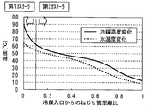
- FIG. 6 is a diagram illustrating temperature changes of the refrigerant and water in the entire first gas cooler 4 and the second gas cooler 5 and the division positions of the first gas cooler 4 and the second gas cooler 5.
- the horizontal axis in FIG. 6 is a ratio to the total length of the first torsion tube 41 and the second torsion tube 51 (that is, the sum of the length of the first liquid heat transfer channel and the length of the second liquid heat transfer channel).
- the origin (0) on the horizontal axis in FIG. 6 represents the water outlet and refrigerant inlet of the first gas cooler 4, and the right end (1) on the horizontal axis represents the water inlet and refrigerant outlet of the second gas cooler 5.
- the high-temperature refrigeration oil also exchanges heat with water.
- the specific heat of the refrigeration oil becomes smaller than the specific heat of the refrigerant gas, there is a concern about a decrease in heating capacity and a reduction in hot water supply efficiency associated therewith. Is done.
- the specific heat of the refrigerant gas greatly increases when the temperature is between 20 ° C and 60 ° C, whereas the specific heat of the refrigeration oil is almost constant regardless of the temperature. It is.
- the temperature of the pinch point at which the temperatures of the refrigerant gas and water are closest is about 50 ° C. Therefore, the upper limit temperature in the range where the specific heat of the refrigerant gas rapidly increases is a temperature obtained by adding 10 ° C. to the pinch point temperature. Therefore, if the outlet temperature of the first refrigerant heat transfer tube 42 of the first gas cooler 4 ( ⁇ the temperature of the second suction passage 36) is higher by 10 ° C.
- the length of the first torsion tube 41 of the first gas cooler 4 with respect to the total length of the first torsion tube 41 and the second torsion tube 51 is It is desirable to configure so as to correspond to about 10% on the high temperature side.
- FIG. 7 is a diagram showing changes in refrigerant density in the entire first gas cooler 4 and second gas cooler 5.
- the meaning of the horizontal axis in FIG. 7 is the same as the horizontal axis in FIG. As shown in FIG. 7, the refrigerant has a lower density as the temperature is higher.
- the pressure loss ⁇ P of the refrigerant in the refrigerant heat transfer tube is obtained by the following equation 1.
- the sectional shape of the refrigerant heat transfer tube is circular.
- ⁇ P ⁇ / di ⁇ ⁇ / 2 ⁇ u 2 ⁇ L (Formula 1)
- ⁇ pipe friction coefficient
- di [m] inner diameter of refrigerant heat transfer tube
- ⁇ [kg / m 3 ] refrigerant density
- u [m / s] refrigerant flow velocity
- L [m] flow path length
- the refrigerant flow velocity u is obtained by the following formulas 2 and 3.
- u Gr / ( ⁇ ⁇ A) (Formula 2)
- A ⁇ / 4 ⁇ di 2 (Formula 3)
- the shape and the refrigerant flow rate of the first refrigerant heat transfer tube 42 and the second refrigerant heat transfer tube 52 are constant, and the pipe friction coefficient ⁇ does not change. From the above formula, the refrigerant pressure loss ⁇ P per unit flow path length is proportional to 1 / ⁇ .
- refrigerant gas containing a large amount of refrigerating machine oil circulates in the first gas cooler 4, and refrigerant gas containing little refrigerating machine oil circulates in the second gas cooler 5.
- the viscosity of the CO 2 gas refrigerant in the first gas cooler 4 is 1, the average viscosity ratio of the refrigerating machine oil is 311.
- the viscosity of the refrigerating machine oil is very large compared to the viscosity of the CO 2 gas refrigerant. For this reason, the pressure loss of the refrigerant gas containing a large amount of refrigerating machine oil increases.
- the mass flow rate of the refrigerating machine oil is Goil [kg / s].
- the oil circulation rate OC is a ratio of the mass flow rate of the refrigerating machine oil to the sum of the mass flow rate of the refrigerant and the mass flow rate of the refrigerating machine oil.
- the oil circulation rate OC of the first gas cooler 4 is preferably 2% or more, and more preferably 5% or more. Further, in the rated operation state of the heat pump device 1, the oil circulation rate OC of the first gas cooler 4 is preferably 20% or less, and more preferably 10% or less.
- the oil circulation rate OC of the first gas cooler 4 By setting the oil circulation rate OC of the first gas cooler 4 to be equal to or higher than the lower limit described above, the heat of the high-temperature refrigeration oil in the compressor 3 can be effectively used for heating the water in the first gas cooler 4, Heating capacity can be improved. Moreover, the refrigerant
- the oil circulation rate OC of the second gas cooler 5 is preferably 0.01% or more, and more preferably 0.1% or more. Further, in the rated operation state of the heat pump device 1, the oil circulation rate OC of the second gas cooler 5 is preferably 1% or less, and more preferably 0.5% or less. By making the oil circulation rate OC of the second gas cooler 5 equal to or less than the above-described upper limit value, the refrigerant pressure loss of the second gas cooler 5 can be reliably suppressed.
- the oil circulation rate OC of the second gas cooler 5 may be lower than the lower limit value described above.
- the refrigerant pressure loss is 1.6. Increases to about 2.0 times.
- FIG. 8 is a diagram showing a ratio of refrigerant pressure loss of the first gas cooler 4 and the second gas cooler 5 when the shapes of the first gas cooler 4 and the second gas cooler 5 are the same except for the channel length.
- FIG. 9 is a configuration diagram of a conventional heat pump apparatus. First, the conventional heat pump apparatus 70 shown in FIG. 9 will be described. Elements common to the heat pump apparatus 1 of the first embodiment are denoted by the same reference numerals, and redundant description is omitted.
- a heat pump device 70 shown in FIG. 9 includes a compressor 71 having one intake passage and one discharge passage instead of the compressor 3 in the heat pump device 1 of the first embodiment.
- the heat pump device 70 includes a single gas cooler 72 instead of the first gas cooler 4 and the second gas cooler 5.
- the low-pressure refrigerant sucked into the compressor 71 from the pipe 21 is compressed by the compressor 71 to become a high-pressure refrigerant.
- the high-pressure refrigerant is discharged from the compressor 71, passes through the pipe 10 and the gas cooler 72, and reaches the pipe 19.
- the oil circulation rate of the entire gas cooler is 0.5% or less
- the gas cooler 72 is replaced with the first gas cooler 4 and the second gas cooler 5 as in the conventional heat pump device 70 of FIG. It means a case where the refrigerant after separating the refrigerating machine oil in the airtight container of the compressor 71 is allowed to flow into the gas cooler 72 without being divided. That is, it means the case of the conventional refrigeration cycle in which the refrigerant is not returned between the first gas cooler 4 and the second gas cooler 5 into the sealed container 31 of the compressor 3.
- the ratio of the refrigerant pressure loss of the portion corresponding to 10% of the refrigerant high temperature side of the entire flow length of the gas cooler 72 is: 0.17.
- the ratio of the remaining refrigerant pressure loss in the portion corresponding to the flow path length of 90% on the low temperature side of the refrigerant is 0.83.
- the ratio of the refrigerant pressure loss occupied by the portion corresponding to 10% of the total flow path length is 17% of the total refrigerant pressure loss. Thus, it becomes larger than the ratio of the channel length.
- the case where “the first gas cooler has a large oil circulation rate and the second gas cooler has an oil circulation rate of 0.5% or less” means that the first gas cooler 4 has an oil circulation rate of 5% to 10%. Therefore, the refrigerant pressure loss is doubled as compared with the case where the oil circulation rate is 0.5% or less.
- 10% of the flow path length on the refrigerant high temperature side corresponds to the first gas cooler 4 with respect to the entire flow path length of the first gas cooler 4 and the second gas cooler 5.
- the refrigerant pressure loss of the entire gas cooler 72 is 1
- the refrigerant pressure loss per unit channel length is large and the refrigerant pressure loss is doubled on the refrigerant high temperature side, the influence on the refrigerant pressure loss of the entire gas cooler is large.
- coolant pressure loss of the whole gas cooler becomes 1.17 time compared with the case where an oil circulation rate is small as a whole.
- coolant pressure loss of the 1st gas cooler 4 accounts to the whole is as large as 29%.
- the first gas cooler 4 has a higher oil circulation rate than the second gas cooler 5, the mainly flowing medium is a refrigerant.
- the form of the heat exchanger which comprises the 1st gas cooler 4 is not an oil cooler type form, but the form of the heat exchanger for normal refrigerant
- coolants is preferable.
- the first gas cooler 4 preferably has a configuration using a torsion tube, similarly to the second gas cooler 5.
- the refrigerant pressure loss of the first gas cooler 4 is reduced as follows.
- the refrigerant pressure loss ⁇ P in the first refrigerant heat transfer tube 42 has the following proportional relationship from the above equations 1 to 3, provided that the pipe friction coefficient, the refrigerant density, and the refrigerant flow rate are constant. ⁇ P ⁇ L / (di1) 5
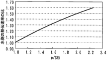
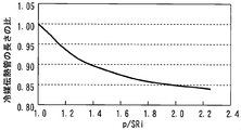
- FIG. 10 is a diagram showing the relationship between the ratio between the twist pitch p and the inner diameter SRi of the first torsion pipe 41 and the heat transfer coefficient on the water side.
- FIG. 10 shows a change in the heat transfer coefficient on the water side when the inner diameter SRi of the first torsion tube 41 is constant and the torsion pitch p is increased.
- the water-side heat transfer coefficient is expressed as a ratio to the water-side heat transfer coefficient value when the value of p / SRi is 1.
- the heat transfer coefficient on the water side tends to increase as p / SRi increases, that is, as the twist pitch p of the first torsion pipe 41 increases.
- FIG. 11 is a diagram showing the relationship between the ratio between the twist pitch p and the inner diameter SRi of the first torsion tube 41 and the required length of the first torsion tube 41.
- the first gas cooler 4 which is a torsion tube heat exchanger, has a structure in which the first refrigerant heat transfer tube 42 is wound along the spiral groove 411 of the first torsion tube 41.
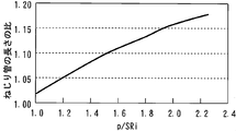
- FIG. 12 is a diagram showing the relationship between the ratio between the twist pitch p and the inner diameter SRi of the first torsion tube 41 and the required length of the first refrigerant heat transfer tube.
- FIG. 12 shows the length of the first refrigerant heat transfer tube 42 required to obtain the same heat exchange amount when the inner diameter SRi of the first torsion tube 41 is constant and the torsion pitch p is increased. Is expressed as a ratio to the length of the first refrigerant heat transfer tube 42 required when the value of 1 is 1. As described with reference to FIG. 11, the required length of the first torsion tube 41 becomes longer as the torsion pitch p of the first torsion tube 41 is increased.
- the twist pitch p of the first torsion tube 41 is increased, the length of the first refrigerant heat transfer tube 42 wound around the unit length of the first torsion tube 41 decreases.
- the required length of the first refrigerant heat transfer tube 42 is shortened as the twist pitch p of the first twist tube 41 is increased.
- the tendency for the required length of the first refrigerant heat transfer tube 42 to decrease decreases.
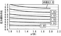
- FIG. 13 is a diagram showing the relationship between the refrigerant pressure loss of the first gas cooler 4, the ratio of the twist pitch p and the inner diameter SRi of the first torsion pipe 41, and the inner diameter di1 of the first refrigerant heat transfer pipe.
- the ratio di1 / di2 of the inner diameter di1 of the first refrigerant heat transfer tube 42 of the first gas cooler 4 to the inner diameter di2 of the second refrigerant heat transfer tube 52 of the second gas cooler is referred to as “inner diameter ratio”.
- FIG. 13 shows the torsion pitch p of the first torsion pipe 41 for each of the cases where the inner diameter ratio di1 / di2 is set to a plurality of values shown in the figure under the condition that the heat exchange amount of the first gas cooler 4 is constant.
- coolant pressure loss of the 1st gas cooler 4 when changing is shown is represented.
- the refrigerant pressure loss of the first gas cooler 4 is expressed as a ratio with respect to the refrigerant pressure loss of the first gas cooler 4 when the values of the inner diameter ratio di1 / di2 and p / SRi are both 1.
- FIG. 14 is a diagram showing the relationship between the ratio of the torsion pitch p and the inner diameter SRi of the first torsion tube 41 of the first gas cooler 4 and the length of the first torsion tube 41 in each case shown in FIG. .
- the length of the first torsion tube 41 is expressed as a ratio with respect to the length of the first torsion tube 41 when both the inner diameter ratio di1 / di2 and the p / SRi value are 1.
- the ratio between the twist pitch p2 of the second torsion pipe 51 of the second gas cooler 5 and the inner diameter SRi is approximately 1.
- the inner diameter SRi of the first torsion tube 41 of the first gas cooler 4 is equal to the inner diameter SRi of the second torsion tube 51 of the second gas cooler 5.
- the refrigerant pressure loss of the first gas cooler 4 decreases as p / SRi increases, that is, the torsion pitch p of the first torsion pipe 41 increases.
- the twist pitch p of the first torsion pipe 41 is the same, the refrigerant pressure loss of the first gas cooler 4 increases as the inner diameter ratio di1 / di2 increases, that is, the inner diameter di1 of the first refrigerant heat transfer pipe 42 increases. Decrease.
- the effect of reducing the refrigerant pressure loss of the first gas cooler 4 increases as the inner diameter ratio di1 / di2 increases, that is, as the inner diameter di1 of the first refrigerant heat transfer tube 42 increases.
- the larger the inner diameter di1 of the first refrigerant heat transfer tube 42 the lower the flow rate of the refrigerant in the first refrigerant heat transfer tube 42 and the lower the heat transfer coefficient in the first refrigerant heat transfer tube 42. Therefore, as shown in FIG. 14, as the inner diameter ratio di1 / di2 is increased, that is, as the inner diameter di1 of the first refrigerant heat transfer tube 42 is increased, the first twisted tube necessary for obtaining the same heat exchange amount. 41 becomes longer.
- the required length of the first torsion tube 41 increases as p / SRi increases, that is, the torsion pitch p of the first torsion tube 41 increases.
- the entire gas cooler including the first gas cooler 4 and the second gas cooler 5 is increased, and the housing of the heat pump device 1 may be enlarged.
- the length of the first torsion tube 41 of the first gas cooler 4 is increased, the material required for the first torsion tube 41 is increased, so that the weight and cost are increased.
- the first torsion pipe 41 serving as a water flow path becomes excessively long, there may be a concern about an increase in the amount of heat released from the first gas cooler 4 to the outside of the heat pump device 1 or an increase in water-side pressure loss. .
- the value of p / SRi which is the ratio between the twist pitch p and the inner diameter SRi of the first twisted tube 41, is preferably 1.8 or less.
- the value of p / SRi of the first torsion pipe 41 of the first gas cooler 4 is preferably 1.1 or more, more preferably 1.2 or more, and further preferably 1.4 or more.
- the length of the first refrigerant heat transfer tube 42 can be effectively shortened. Yes (see FIG. 12). As a result, the refrigerant pressure loss of the first gas cooler 4 can be more reliably reduced.
- the value of p / SRi of the first torsion pipe 41 of the first gas cooler 4 is preferably 1.1 or more and 1.8 or less, more preferably 1.2 or more and 1.8 or less, and 1.4 or more. 1.8 or less is more preferable.
- the first torsion pipe 41 is sufficiently increased in the torsion pitch p, and the effect of reducing the refrigerant pressure loss of the first gas cooler 4 is sufficiently increased.
- a markedly superior effect is obtained in that the adverse effects associated with the length of the tube 41 can be reliably suppressed.
- FIG. 15 shows the first case where the inner diameter ratio di1 / di2 of the first refrigerant heat transfer tube 42 and the second refrigerant heat transfer tube 52 is changed when the value of p / SRi of the first torsion tube 41 is 1.8. It is a figure which shows the change of the refrigerant
- the refrigerant pressure loss of the first gas cooler 4 is expressed as a ratio to the sum of the refrigerant pressure loss of the first gas cooler 4 and the refrigerant pressure loss of the second gas cooler 5 (that is, the refrigerant pressure loss of the entire gas cooler).
- the inner diameter ratio di1 / di2 is larger, that is, as the inner diameter di1 of the first refrigerant heat transfer tube 42 is larger, the refrigerant pressure loss of the first gas cooler 4 decreases, and the refrigerant pressure loss with respect to the refrigerant pressure loss of the entire gas cooler decreases.
- the ratio of the refrigerant pressure loss of the one gas cooler 4 becomes small. However, as shown in FIG.
- the channel length of the first gas cooler 4 occupies about 10% of the channel length of the entire gas cooler. Therefore, if the ratio of the refrigerant pressure loss of the first gas cooler 4 to the refrigerant pressure loss of the entire gas cooler can be reduced to about 10%, it can be said that the refrigerant pressure loss of the first gas cooler 4 is sufficiently reduced.
- the refrigerant pressure loss of the first gas cooler 4 is further reduced, that is, the refrigerant pressure loss per unit flow path length of the first gas cooler 4 is made larger than the refrigerant pressure loss per unit flow path length of the second gas cooler 5. Making it smaller can be said to go too far. As shown in FIG.
- the ratio of the refrigerant pressure loss of the first gas cooler 4 to the refrigerant pressure loss of the entire gas cooler is about 10%. Therefore, if the value of the inner diameter ratio di1 / di2 is set to 1.4, it can be said that the refrigerant pressure loss of the first gas cooler 4 is sufficiently reduced in relation to the ratio of the flow path length.
- the value of the inner diameter ratio di1 / di2 is excessively increased, that is, if the inner diameter di1 of the first refrigerant heat transfer tube 42 is excessively increased, the length of the first torsion tube 41 becomes excessive or the first gas cooler 4 There is a possibility that the above-mentioned detrimental effect of increasing the amount of refrigerating machine oil remaining will occur.
- the value of the inner diameter ratio di1 / di2 is 1.4 or less, the inner diameter di1 of the first refrigerant heat transfer tube 42 will not be too large, and such an adverse effect can be reliably suppressed.
- the value of the inner diameter ratio di1 / di2 of the first refrigerant heat transfer tube 42 and the second refrigerant heat transfer tube 52 is preferably 1.1 or more, and more preferably 1.2 or more.
- the value of the inner diameter ratio di1 / di2 is preferably 1.1 or more and 1.4 or less, and more preferably 1.2 or more and 1.4 or less.
- the refrigerant pressure of the first gas cooler 4 can be surely suppressed while preventing the above-described adverse effects caused by making the inner diameter di1 of the first refrigerant heat transfer tube 42 too large. A remarkable effect is obtained that the loss can be sufficiently reduced.
- the refrigerant pressure loss of the first gas cooler 4 can be reliably suppressed, so that the input of the compressor 3 can be reduced and the COP can be improved.
- the refrigerant density in the second gas cooler 5 is larger than the refrigerant density in the first gas cooler 4.
- the larger the refrigerant density the smaller the refrigerant pressure loss per unit channel length. Therefore, when other conditions are the same, the refrigerant pressure loss per length of the second refrigerant heat transfer tube 52 of the second gas cooler 5 becomes the refrigerant pressure loss per length of the first refrigerant heat transfer tube 42 of the first gas cooler 4. Smaller than that.
- the inner diameter di2 of the second refrigerant heat transfer tube 52 of the second gas cooler 5 or the cross-sectional area of each second refrigerant heat transfer channel is equal to the inner diameter di1 of the first refrigerant heat transfer tube 42 of the first gas cooler 4 or the first of each. Even if it is smaller than the cross-sectional area of the refrigerant heat transfer channel, the refrigerant pressure loss of the second gas cooler 5 can be sufficiently suppressed. Further, by making the inner diameter di2 of the second refrigerant heat transfer tube 52 of the second gas cooler 5 or the cross-sectional area of each second refrigerant heat transfer channel relatively small, the second refrigerant heat transfer tube 52, that is, each of the second refrigerant transfer tubes.
- the heat transfer coefficient of the refrigerant can be increased.
- the length of the second torsion pipe 51 of the second gas cooler that is, the second liquid heat transfer channel can be shortened.
- the inner diameter di1 of the first refrigerant heat transfer tube 42 of the first gas cooler 4 or the cross-sectional area of each first refrigerant heat transfer channel is equal to the inner diameter di2 of the second refrigerant heat transfer tube 52 of the second gas cooler 5 or each.
- the cross-sectional area of the second refrigerant heat transfer channel is preferably large.
- FIG. 16 shows the case where the twist pitch p of the first torsion tube 41 is equal to the torsion pitch p2 of the second torsion tube 51 and the inner diameter SRi of the first torsion tube 41 and the second torsion tube 51 is equal. It is a figure which shows the change of the heat transfer coefficient.
- the meaning of the horizontal axis in FIG. 16 is the same as the horizontal axis in FIG.
- the water-side heat transfer coefficient is expressed as a ratio to the water-side heat transfer coefficient at the water outlet of the first gas cooler 4. As shown in FIG. 16, the heat transfer coefficient on the water side decreases as the distance from the refrigerant inlet and the water outlet of the first gas cooler 4 increases, that is, as the water temperature decreases.
- the second gas cooler 5 When the torsion pitch p of the first torsion tube 41 and the torsion pitch p2 of the second torsion tube 51 are equal and the inner diameter SRi of the first torsion tube 41 and the second torsion tube 51 is equal, the second gas cooler 5 The water-side heat transfer coefficient is smaller than the water-side heat transfer coefficient of the first gas cooler 4. In view of this point, in the second gas cooler 5, the contact area between the second refrigerant heat transfer tube 52 and the second torsion tube 51 can be increased by relatively reducing the torsion pitch p2 of the second torsion tube 51. desirable. Thereby, the length of the 2nd torsion pipe
- the torsion pitch p of the first torsion pipe 41 of the first gas cooler 4 is desirably relatively large. From the above, it is preferable that the torsion pitch p of the first torsion tube 41 of the first gas cooler 4 is larger than the torsion pitch p2 of the second torsion tube 51 of the second gas cooler 5.
- the inner diameter SRi of the first torsion tube 41 of the first gas cooler 4 it is preferable to make the inner diameter SRi of the first torsion tube 41 of the first gas cooler 4 equal to the inner diameter SRi of the second torsion tube 51 of the second gas cooler 5.
- the upstream end of the first torsion pipe 41 and the downstream end of the second torsion pipe 51 are connected.
- both can be easily connected.
- the inner diameter SRi of the first torsion tube 41 equal to the inner diameter SRi of the second torsion tube 51, the material and the manufacturing method used for both can be made common, and the cost is reduced.
- the number of first refrigerant heat transfer tubes 42 of the first gas cooler 4, that is, the number of first refrigerant heat transfer channels, and the number of second refrigerant heat transfer tubes 52 of the second gas cooler 5, that is, second refrigerant heat transfer flows.
- the number of paths is equal.
- first heat exchanger first gas cooler 4
- second heat exchanger second gas cooler 5
- first heat exchanger and the second heat exchanger are not limited to the twisted tube heat exchanger, and various types of heat exchangers can be used.
- the inner diameter ratio di1 / di2 of the first refrigerant heat transfer tube 42 and the second refrigerant heat transfer tube 52 is preferably 1.1 or more and 1.4 or less, and preferably 1.2 or more and 1.4 or less. More preferred.
- the ratio of the total cross-sectional area of the first refrigerant heat transfer channel of the first heat exchanger to the total cross-sectional area of the second refrigerant heat transfer channel of the second heat exchanger is: (1.1) 2 ⁇ 1.2.
- the ratio of the total cross-sectional area of the first refrigerant heat transfer channel of the first heat exchanger to the total cross-sectional area of the second refrigerant heat transfer channel of the second heat exchanger is (1.2) 2 ⁇ 1.4.
- the ratio of the total cross-sectional area of the first refrigerant heat transfer channel of the first heat exchanger to the total cross-sectional area of the second refrigerant heat transfer channel of the second heat exchanger is (1.4) 2 ⁇ 2.
- the ratio of the total cross-sectional area of the first refrigerant heat transfer channel to the total cross-sectional area of the second refrigerant heat transfer channel is 1.2 or more and 2 or less, and preferably 1.4 or more and 2 or less.
- the number of first refrigerant heat transfer channels may be larger than the number of second refrigerant heat transfer channels.
- the entire cross-sectional area of the first refrigerant heat transfer channel is set to the total of the second refrigerant heat transfer channels with a simple configuration. It can be larger than the cross-sectional area.
- the cross-sectional area of the first refrigerant heat transfer channel is equal to the cross-sectional area of the second refrigerant heat transfer channel. May be.
- coolant heat exchanger tube 52 of the 2nd gas cooler 5 can be manufactured with a common material, and cost reduces.
- the heat pump device that heats water using the first heat exchanger and the second heat exchanger has been described as an example.
- the first heat exchanger and the second heat exchanger are used.
- the liquid to be heated is not limited to water, and may be, for example, brine or antifreeze.
Abstract
The purpose of the present invention is to improve COP for a heat pump device that comprises a compressor having a first discharge path and a second discharge path and for which the mass flow rate of refrigerating machine oil discharged along with a refrigerant from the first discharge path is greater than the mass flow rate of the refrigerating machine oil discharged along with a refrigerant from the second discharge path. This heat pump device comprises: a compressor for which the mass flow rate of a refrigerating machine oil discharged from a first discharge path is greater than the mass flow rate of a refrigerating machine oil discharged from a second discharge path; a first heat exchanger having a first refrigerant heat transfer channel through which the refrigerant and the refrigerating machine oil discharged from the first discharge path pass and a first liquid heat transfer channel through which a liquid passes; and a second heat exchanger having a second refrigerant heat transfer channel through which the refrigerant and the refrigerating machine oil discharged from the second discharge path pass and a second liquid heat transfer channel through which a liquid passes. The total cross-sectional area of the first refrigerant heat transfer channel is larger than the total cross-sectional area of the second refrigerant heat transfer channel.
Description
本発明は、ヒートポンプ装置に関する。
The present invention relates to a heat pump device.
特許文献1には、高温側冷媒配管、低温側冷媒配管および水配管を有するガスクーラと、密閉容器、圧縮要素、電動要素、吸入管、吐出管、冷媒再導入管および冷媒再吐出管を有する給湯用圧縮機とを備えた給湯サイクル装置が開示されている。この装置では、低圧冷媒を吸入管が圧縮要素に直接導き、圧縮要素で圧縮した高圧冷媒を密閉容器内に放出することなく吐出管より密閉容器外に直接吐出し、この高圧冷媒が高温側冷媒配管を通って熱交換した後の冷媒を冷媒再導入管より密閉容器内に導き、密閉容器内で電動要素を通過した後の冷媒を冷媒再吐出管より密閉容器外に再吐出し、低温側冷媒配管へ送る。
Patent Document 1 discloses a hot water supply having a gas cooler having a high temperature side refrigerant pipe, a low temperature side refrigerant pipe and a water pipe, and a sealed container, a compression element, an electric element, a suction pipe, a discharge pipe, a refrigerant reintroduction pipe and a refrigerant redischarge pipe. A hot water supply cycle device including a compressor is disclosed. In this apparatus, the suction pipe guides the low-pressure refrigerant directly to the compression element, and the high-pressure refrigerant compressed by the compression element is discharged directly from the discharge pipe to the outside of the sealed container without being discharged into the sealed container. The refrigerant after heat exchange through the pipe is guided into the sealed container from the refrigerant reintroduction pipe, and the refrigerant after passing through the electric element in the sealed container is re-discharged out of the sealed container from the refrigerant re-discharge pipe. Send to refrigerant piping.
上述した従来の装置では、圧縮要素の圧縮室内に、摺動部を潤滑およびシールし、摩擦および隙間漏れを軽減するために、冷凍機油が供給される。このため、圧縮機の吐出管からは、圧縮された冷媒ガスとともに、多量の冷凍機油が圧縮機外部へ吐出され、高温側冷媒配管へ循環する。一方、この圧縮機の冷媒再吐出管から吐出される冷媒に含まれる冷凍機油の量は、吐出管に比べて、大幅に少ない。
In the conventional apparatus described above, refrigerating machine oil is supplied into the compression chamber of the compression element in order to lubricate and seal the sliding portion and reduce friction and gap leakage. For this reason, a large amount of refrigerating machine oil is discharged from the discharge pipe of the compressor together with the compressed refrigerant gas to the outside of the compressor and circulates to the high temperature side refrigerant pipe. On the other hand, the amount of refrigerating machine oil contained in the refrigerant discharged from the refrigerant re-discharge pipe of the compressor is significantly smaller than that of the discharge pipe.
冷凍機油は、冷媒に比べて、粘度が極めて大きい。このため、上述した従来の装置において、冷媒とともに多量の冷凍機油が高温側冷媒配管に循環するので、冷媒の圧力損失が大きくなる。その結果、圧縮機の吐出圧力が高くなり、圧縮機の入力が増加するため、COP(Coefficient Of Performance)が低下する。
Refrigerator oil has a very high viscosity compared to refrigerant. For this reason, in the conventional apparatus described above, a large amount of refrigerating machine oil circulates in the high-temperature side refrigerant pipe together with the refrigerant, so that the pressure loss of the refrigerant increases. As a result, the discharge pressure of the compressor increases and the input of the compressor increases, so that COP (Coefficient Of Performance) decreases.
本発明は、上述のような課題を解決するためになされたもので、第1吐出通路および第2吐出通路を有する圧縮機を備え、第1吐出通路から冷媒とともに吐出される冷凍機油の質量流量が第2吐出通路から冷媒とともに吐出される冷凍機油の質量流量に比べて多いヒートポンプ装置において、COPを向上することを目的とする。
The present invention has been made to solve the above-described problems, and includes a compressor having a first discharge passage and a second discharge passage, and a mass flow rate of refrigerating machine oil discharged together with refrigerant from the first discharge passage. An object of the present invention is to improve COP in a heat pump device in which the amount of refrigerant is larger than the mass flow rate of refrigerating machine oil discharged together with refrigerant from the second discharge passage.
本発明に係るヒートポンプ装置は、冷媒および冷凍機油を吐出する第1吐出通路と、冷媒および冷凍機油を吐出する第2吐出通路とを有し、第1吐出通路から吐出される冷凍機油の質量流量が第2吐出通路から吐出される冷凍機油の質量流量に比べて多い圧縮機と、第1吐出通路から吐出された冷媒および冷凍機油が通る1または複数の第1冷媒伝熱流路と、液体が通る1または複数の第1液体伝熱流路とを有し、第1冷媒伝熱流路と第1液体伝熱流路との間で熱交換する第1熱交換器と、第2吐出通路から吐出された冷媒および冷凍機油が通る1または複数の第2冷媒伝熱流路と、液体が通る1または複数の第2液体伝熱流路とを有し、第2冷媒伝熱流路と第2液体伝熱流路との間で熱交換する第2熱交換器と、を備え、第1冷媒伝熱流路の全断面積が第2冷媒伝熱流路の全断面積に比べて大きいものである。
The heat pump device according to the present invention has a first discharge passage for discharging refrigerant and refrigeration oil, and a second discharge passage for discharging refrigerant and refrigeration oil, and the mass flow rate of the refrigeration oil discharged from the first discharge passage. Is larger than the mass flow rate of the refrigerating machine oil discharged from the second discharge passage, one or a plurality of first refrigerant heat transfer passages through which the refrigerant discharged from the first discharge passage and the refrigerating machine oil pass, and the liquid A first heat exchanger having one or a plurality of first liquid heat transfer channels passing therethrough and exchanging heat between the first refrigerant heat transfer channel and the first liquid heat transfer channel, and discharged from the second discharge passage. The second refrigerant heat transfer channel and the second liquid heat transfer channel have one or more second refrigerant heat transfer channels through which the refrigerant and refrigerating machine oil pass, and one or more second liquid heat transfer channels through which the liquid passes. A second heat exchanger for exchanging heat with the first refrigerant heat transfer flow The total cross-sectional area of the is larger than the total cross-sectional area of the second refrigerant heat transfer passages.
本発明に係るヒートポンプ装置によれば、冷凍機油の吐出量が多い第1吐出通路から吐出される冷媒および冷凍機油が循環する第1熱交換器の冷媒の圧力損失を確実に抑制することができる。このため、圧縮機の入力を低減し、COPを向上することが可能となる。
According to the heat pump device of the present invention, it is possible to reliably suppress the pressure loss of the refrigerant discharged from the first discharge passage where the discharge amount of the refrigerating machine oil is large and the refrigerant of the first heat exchanger through which the refrigerating machine oil circulates. . For this reason, it becomes possible to reduce the input of a compressor and to improve COP.
以下、図面を参照して本発明の実施の形態について説明する。なお、各図において共通する要素には、同一の符号を付して、重複する説明を省略する。また、以下の説明では、簡単のため、流路長のことを、単に「長さ」と称する場合がある。
実施の形態1.
図1は、本発明の実施の形態1のヒートポンプ装置を示す構成図である。図2は、図1に示すヒートポンプ装置を備えた貯湯式給湯システムを示す構成図である。図1に示すように、本実施の形態1のヒートポンプ装置1は、圧縮機3と、第1熱交換器としての第1ガスクーラ4と、第2熱交換器としての第2ガスクーラ5と、膨張手段としての膨張弁6と、蒸発器7とを冷媒配管により接続した冷媒回路を備える。第1ガスクーラ4は、第1冷媒伝熱流路と、第1液体伝熱流路とを有し、第1冷媒伝熱流路と第1液体伝熱流路との間で熱交換する。第2ガスクーラ5は、第2冷媒伝熱流路と、第2液体伝熱流路とを有し、第2冷媒伝熱流路と第2液体伝熱流路との間で熱交換する。ヒートポンプ装置1は、第1ガスクーラ4の第1液体伝熱流路および第2ガスクーラ5の第2液体伝熱流路に、熱媒体または被加熱物となる液体を流通させ、この液体を加熱する。本実施の形態1のヒートポンプ装置では、加熱される液体は、水である。本実施の形態1における蒸発器7は、空気と冷媒との熱交換を行う空気冷媒熱交換器で構成されている。また、本実施の形態1のヒートポンプ装置1は、蒸発器7に送風する送風機8と、高圧冷媒と低圧冷媒との熱交換を行う高低圧熱交換器9とを更に備えている。ヒートポンプ装置1は、水を加熱する加熱運転時には、圧縮機3を作動させることにより、ヒートポンプサイクル(冷凍サイクル)を稼動させる。 Embodiments of the present invention will be described below with reference to the drawings. In addition, the same code | symbol is attached | subjected to the element which is common in each figure, and the overlapping description is abbreviate | omitted. In the following description, for the sake of simplicity, the channel length may be simply referred to as “length”.
Embodiment 1 FIG.
FIG. 1 is a configuration diagram illustrating a heat pump apparatus according toEmbodiment 1 of the present invention. FIG. 2 is a configuration diagram illustrating a hot water storage type hot water supply system including the heat pump device illustrated in FIG. 1. As shown in FIG. 1, the heat pump device 1 of the first embodiment includes a compressor 3, a first gas cooler 4 as a first heat exchanger, a second gas cooler 5 as a second heat exchanger, and expansion. The refrigerant circuit which connected the expansion valve 6 and the evaporator 7 as a means by refrigerant | coolant piping is provided. The first gas cooler 4 has a first refrigerant heat transfer channel and a first liquid heat transfer channel, and exchanges heat between the first refrigerant heat transfer channel and the first liquid heat transfer channel. The second gas cooler 5 has a second refrigerant heat transfer channel and a second liquid heat transfer channel, and exchanges heat between the second refrigerant heat transfer channel and the second liquid heat transfer channel. The heat pump device 1 circulates a liquid serving as a heat medium or an object to be heated through the first liquid heat transfer channel of the first gas cooler 4 and the second liquid heat transfer channel of the second gas cooler 5, and heats the liquid. In the heat pump device of the first embodiment, the liquid to be heated is water. The evaporator 7 in this Embodiment 1 is comprised with the air refrigerant | coolant heat exchanger which performs heat exchange with air and a refrigerant | coolant. The heat pump device 1 according to the first embodiment further includes a blower 8 that blows air to the evaporator 7 and a high-low pressure heat exchanger 9 that performs heat exchange between the high-pressure refrigerant and the low-pressure refrigerant. The heat pump device 1 operates a heat pump cycle (refrigeration cycle) by operating the compressor 3 during a heating operation for heating water.
実施の形態1.
図1は、本発明の実施の形態1のヒートポンプ装置を示す構成図である。図2は、図1に示すヒートポンプ装置を備えた貯湯式給湯システムを示す構成図である。図1に示すように、本実施の形態1のヒートポンプ装置1は、圧縮機3と、第1熱交換器としての第1ガスクーラ4と、第2熱交換器としての第2ガスクーラ5と、膨張手段としての膨張弁6と、蒸発器7とを冷媒配管により接続した冷媒回路を備える。第1ガスクーラ4は、第1冷媒伝熱流路と、第1液体伝熱流路とを有し、第1冷媒伝熱流路と第1液体伝熱流路との間で熱交換する。第2ガスクーラ5は、第2冷媒伝熱流路と、第2液体伝熱流路とを有し、第2冷媒伝熱流路と第2液体伝熱流路との間で熱交換する。ヒートポンプ装置1は、第1ガスクーラ4の第1液体伝熱流路および第2ガスクーラ5の第2液体伝熱流路に、熱媒体または被加熱物となる液体を流通させ、この液体を加熱する。本実施の形態1のヒートポンプ装置では、加熱される液体は、水である。本実施の形態1における蒸発器7は、空気と冷媒との熱交換を行う空気冷媒熱交換器で構成されている。また、本実施の形態1のヒートポンプ装置1は、蒸発器7に送風する送風機8と、高圧冷媒と低圧冷媒との熱交換を行う高低圧熱交換器9とを更に備えている。ヒートポンプ装置1は、水を加熱する加熱運転時には、圧縮機3を作動させることにより、ヒートポンプサイクル(冷凍サイクル)を稼動させる。 Embodiments of the present invention will be described below with reference to the drawings. In addition, the same code | symbol is attached | subjected to the element which is common in each figure, and the overlapping description is abbreviate | omitted. In the following description, for the sake of simplicity, the channel length may be simply referred to as “length”.
FIG. 1 is a configuration diagram illustrating a heat pump apparatus according to
図2に示すように、本実施の形態1のヒートポンプ装置1は、タンクユニット2と組み合わせることによって、貯湯式給湯システムとして用いることができる。タンクユニット2内には、湯水を貯留する貯湯タンク2aと、水ポンプ2bとが設置されている。ヒートポンプ装置1と、タンクユニット2とは、水が流れる管11および管12と、図示しない電気配線とを介して接続される。管11の一端は、ヒートポンプ装置1の水入口1aに接続されている。管11の他端は、タンクユニット2内で貯湯タンク2aの下部に接続されている。タンクユニット2内の管11の途中に水ポンプ2bが設置されている。管12の一端は、ヒートポンプ装置1の水出口1bに接続されている。管12の他端は、タンクユニット2内で貯湯タンク2aの上部に接続されている。図示の構成に代えて、水ポンプ2bをヒートポンプ装置1内に配置してもよい。
As shown in FIG. 2, the heat pump device 1 of the first embodiment can be used as a hot water storage type hot water supply system by combining with the tank unit 2. In the tank unit 2, a hot water storage tank 2a for storing hot water and a water pump 2b are installed. The heat pump device 1 and the tank unit 2 are connected via a pipe 11 and a pipe 12 through which water flows and an electric wiring (not shown). One end of the tube 11 is connected to the water inlet 1 a of the heat pump device 1. The other end of the pipe 11 is connected to the lower part of the hot water storage tank 2 a in the tank unit 2. A water pump 2 b is installed in the middle of the pipe 11 in the tank unit 2. One end of the pipe 12 is connected to the water outlet 1 b of the heat pump device 1. The other end of the pipe 12 is connected to the upper part of the hot water storage tank 2 a in the tank unit 2. Instead of the illustrated configuration, the water pump 2b may be disposed in the heat pump device 1.
図1に示すように、ヒートポンプ装置1の圧縮機3は、密閉容器31と、この密閉容器31内に設けられた圧縮要素32および電動要素33と、第1吸入通路34と、第1吐出通路35と、第2吸入通路36と、第2吐出通路37とを有している。第1吸入通路34から吸入された低圧冷媒は、密閉容器31の内部空間38に放出されることなく、直接、圧縮要素32内へ流入する。圧縮要素32は、電動要素33により駆動され、低圧冷媒を圧縮し、高圧冷媒にする。圧縮要素32で圧縮された高圧冷媒は、密閉容器31の内部空間38に放出されることなく、第1吐出通路35を通って、直接、密閉容器31外に吐出される。第1吐出通路35から吐出された高圧冷媒は、管10を通って、第1ガスクーラ4に流入する。第1ガスクーラ4を通過した高圧冷媒は、管17を通って、圧縮機3の第2吸入通路36に至る。第2吸入通路36から圧縮機3に吸入された高圧冷媒は、密閉容器31の内部空間38に放出される。本実施の形態1では、電動要素33の下に圧縮要素32が配置されている。第2吸入通路36の出口は、密閉容器31の内部空間38において、電動要素33と圧縮要素32との間の高さに開口している。第2吐出通路37の入口は、密閉容器31の内部空間38において、電動要素33より上の高さに開口している。第2吸入通路36の出口から密閉容器31の内部空間38に放出された高圧冷媒は、電動要素33の回転子331と固定子332との隙間等を通って電動要素33の上に至り、第2吐出通路37を通って、密閉容器31外に吐出される。第2吐出通路37から吐出された高圧冷媒は、管18を通って、第2ガスクーラ5に流入する。第2ガスクーラ5を通過した高圧冷媒は、管19を通って、膨張弁6に至る。高圧冷媒は、膨張弁6を通過することにより、低圧冷媒となる。この低圧冷媒は、管20を通って、蒸発器7に流入する。蒸発器7を通過した低圧冷媒は、管21を通って圧縮機3の第1吸入通路34に至り、圧縮機3に吸入される。高低圧熱交換器9は、管19を通る高圧冷媒と、管21を通る低圧冷媒とを熱交換させる。第1吐出通路35から吐出された高圧冷媒は、第1ガスクーラ4を経由して第2吸入通路36に戻る間の圧力損失により、低下する。このため、密閉容器31の内部空間38の高圧冷媒の圧力PH2は、第1吐出通路35から吐出された高圧冷媒の圧力PH1に比べて、低い。すなわち、第1吐出通路35の吐出圧力PH1は、第2吐出通路37の吐出圧力PH2に比べて、高い。
As shown in FIG. 1, the compressor 3 of the heat pump apparatus 1 includes a sealed container 31, a compression element 32 and an electric element 33 provided in the sealed container 31, a first suction passage 34, and a first discharge passage. 35, a second suction passage 36, and a second discharge passage 37. The low-pressure refrigerant sucked from the first suction passage 34 flows directly into the compression element 32 without being discharged into the internal space 38 of the sealed container 31. The compression element 32 is driven by the electric element 33 and compresses the low-pressure refrigerant into a high-pressure refrigerant. The high-pressure refrigerant compressed by the compression element 32 is discharged directly outside the sealed container 31 through the first discharge passage 35 without being discharged into the internal space 38 of the sealed container 31. The high-pressure refrigerant discharged from the first discharge passage 35 passes through the pipe 10 and flows into the first gas cooler 4. The high-pressure refrigerant that has passed through the first gas cooler 4 passes through the pipe 17 and reaches the second suction passage 36 of the compressor 3. The high-pressure refrigerant sucked into the compressor 3 from the second suction passage 36 is discharged into the internal space 38 of the sealed container 31. In the first embodiment, the compression element 32 is disposed under the electric element 33. The outlet of the second suction passage 36 opens at a height between the electric element 33 and the compression element 32 in the internal space 38 of the sealed container 31. The inlet of the second discharge passage 37 opens at a height above the electric element 33 in the internal space 38 of the sealed container 31. The high-pressure refrigerant released from the outlet of the second suction passage 36 into the internal space 38 of the hermetic container 31 passes through the gap between the rotor 331 and the stator 332 of the electric element 33 and reaches the electric element 33. It is discharged out of the sealed container 31 through the two discharge passages 37. The high-pressure refrigerant discharged from the second discharge passage 37 passes through the pipe 18 and flows into the second gas cooler 5. The high-pressure refrigerant that has passed through the second gas cooler 5 passes through the pipe 19 and reaches the expansion valve 6. The high-pressure refrigerant becomes a low-pressure refrigerant by passing through the expansion valve 6. This low-pressure refrigerant flows into the evaporator 7 through the pipe 20. The low-pressure refrigerant that has passed through the evaporator 7 reaches the first suction passage 34 of the compressor 3 through the pipe 21 and is sucked into the compressor 3. The high / low pressure heat exchanger 9 exchanges heat between the high-pressure refrigerant passing through the pipe 19 and the low-pressure refrigerant passing through the pipe 21. The high-pressure refrigerant discharged from the first discharge passage 35 decreases due to pressure loss while returning to the second suction passage 36 via the first gas cooler 4. For this reason, the pressure PH2 of the high-pressure refrigerant in the internal space 38 of the sealed container 31 is lower than the pressure PH1 of the high-pressure refrigerant discharged from the first discharge passage 35. That is, the discharge pressure PH1 of the first discharge passage 35 is higher than the discharge pressure PH2 of the second discharge passage 37.
ヒートポンプ装置1は、水入口1aから流入した水を第2ガスクーラ5の水入口に導く水流路23と、第1ガスクーラ4の水出口から流出した水(湯)を水出口1bに導く水流路26とを更に備えている。また、第2ガスクーラ5の水出口は、第1ガスクーラ4の水入口に接続されている。加熱運転時には、水入口1aから流入した水が水流路23を通って第2ガスクーラ5に流入し、第2ガスクーラ5内で冷媒の熱により加熱される。第2ガスクーラ5内で加熱されることで生成した湯は、第1ガスクーラ4に流入し、第1ガスクーラ4内で冷媒の熱により更に加熱される。第1ガスクーラ4内で更に加熱されることで更に高温になった湯は、水流路26を通って水出口1bに至り、管12を通ってタンクユニット2へ送られる。
The heat pump device 1 includes a water flow path 23 that guides water flowing from the water inlet 1a to the water inlet of the second gas cooler 5, and a water flow path 26 that guides water (hot water) flowing out of the water outlet of the first gas cooler 4 to the water outlet 1b. Are further provided. The water outlet of the second gas cooler 5 is connected to the water inlet of the first gas cooler 4. During the heating operation, the water flowing in from the water inlet 1 a flows into the second gas cooler 5 through the water flow path 23 and is heated by the heat of the refrigerant in the second gas cooler 5. Hot water generated by being heated in the second gas cooler 5 flows into the first gas cooler 4 and is further heated by the heat of the refrigerant in the first gas cooler 4. Hot water that has been heated further by being further heated in the first gas cooler 4 reaches the water outlet 1 b through the water flow path 26, and is sent to the tank unit 2 through the pipe 12.
冷媒としては、高温出湯ができる冷媒、例えば、二酸化炭素、R410A、プロパン、プロピレンなどの冷媒が適しているが、特にこれらに限定されるものではない。
As the refrigerant, a refrigerant capable of producing high temperature hot water, for example, a refrigerant such as carbon dioxide, R410A, propane, propylene or the like is suitable, but is not particularly limited thereto.
圧縮機3の第1吐出通路35から吐出された高温高圧の冷媒ガスは、第1ガスクーラ4を通過する間に放熱しながら温度低下する。本実施の形態1では、第1ガスクーラ4を通過する間に温度低下した冷媒が第2吸入通路36から密閉容器31の内部空間38に吸入され、電動要素33を冷却する。これにより、電動要素33の温度および密閉容器31の表面温度を低下させることができる。その結果、電動要素33のモータ効率を向上することができ、また、密閉容器31の表面からの放熱ロスを低減することができる。密閉容器31の内部空間38に吸入された冷媒ガスは、電動要素33の熱を奪うことで温度上昇した後、第2吐出通路37から吐出されて第2ガスクーラ5に流入し、第2ガスクーラ5を通過する間に放熱しながら温度低下する。この温度低下した高圧冷媒は、高低圧熱交換器9を通過する間に低圧冷媒を加熱した後、膨張弁6を通過する。膨張弁6を通過することにより、冷媒は、低圧気液二相の状態に減圧される。膨張弁6を通過した冷媒は、蒸発器7を通過する間に外気から吸熱し、蒸発ガス化される。蒸発器7を出た低圧冷媒は、高低圧熱交換器9にて加熱された後、第1吸入通路34から圧縮機3内に吸入される。
The high-temperature and high-pressure refrigerant gas discharged from the first discharge passage 35 of the compressor 3 decreases in temperature while dissipating heat while passing through the first gas cooler 4. In the first embodiment, the refrigerant whose temperature has decreased while passing through the first gas cooler 4 is sucked into the internal space 38 of the sealed container 31 from the second suction passage 36 to cool the electric element 33. Thereby, the temperature of the electric element 33 and the surface temperature of the sealed container 31 can be lowered. As a result, the motor efficiency of the electric element 33 can be improved, and the heat dissipation loss from the surface of the sealed container 31 can be reduced. The refrigerant gas sucked into the internal space 38 of the hermetic container 31 rises in temperature by removing heat from the electric element 33, and then is discharged from the second discharge passage 37 and flows into the second gas cooler 5. The temperature drops while passing through the heat. The high-pressure refrigerant whose temperature has been lowered passes through the expansion valve 6 after heating the low-pressure refrigerant while passing through the high-low pressure heat exchanger 9. By passing through the expansion valve 6, the refrigerant is decompressed to a low-pressure gas-liquid two-phase state. The refrigerant that has passed through the expansion valve 6 absorbs heat from the outside air while passing through the evaporator 7 and is evaporated into gas. The low-pressure refrigerant exiting the evaporator 7 is heated by the high-low pressure heat exchanger 9 and then sucked into the compressor 3 from the first suction passage 34.
高圧冷媒圧力が臨界圧以上であれば、第1ガスクーラ4および第2ガスクーラ5内の冷媒は、超臨界状態のまま気液相転移しないで温度低下して放熱する。また、高圧冷媒圧力が臨界圧以下であれば、冷媒は液化しながら放熱する。本実施の形態1では、冷媒として二酸化炭素等を用いることにより、高圧冷媒圧力を臨界圧以上にすることが好ましい。高圧冷媒圧力が臨界圧以上の場合には、液化した冷媒が第2吸入通路36から密閉容器31の内部空間38に流入することを確実に防止することができる。このため、液化した冷媒が電動要素33に付着することを確実に防止することができ、電動要素33の回転抵抗を低減することができる。また、液化した冷媒が第2吸入通路36から密閉容器31の内部空間38に流入しないことにより、冷凍機油が冷媒によって希釈されることを防止するという利点もある。
If the high-pressure refrigerant pressure is equal to or higher than the critical pressure, the refrigerant in the first gas cooler 4 and the second gas cooler 5 is radiated by lowering the temperature without undergoing a gas-liquid phase transition in a supercritical state. Further, when the high-pressure refrigerant pressure is lower than the critical pressure, the refrigerant dissipates heat while liquefying. In the first embodiment, it is preferable to set the high-pressure refrigerant pressure to a critical pressure or higher by using carbon dioxide or the like as the refrigerant. When the high-pressure refrigerant pressure is equal to or higher than the critical pressure, the liquefied refrigerant can be reliably prevented from flowing into the internal space 38 of the sealed container 31 from the second suction passage 36. For this reason, it can prevent reliably that the liquefied refrigerant | coolant adheres to the electric element 33, and the rotational resistance of the electric element 33 can be reduced. Further, since the liquefied refrigerant does not flow into the internal space 38 of the sealed container 31 from the second suction passage 36, there is an advantage that the refrigerating machine oil is prevented from being diluted by the refrigerant.
図2に示すように、タンクユニット2の貯湯タンク2aの下部には、給水管13が更に接続されている。水道等の外部の水源から供給される水が、給水管13を通って、貯湯タンク2a内に流入し、貯留される。貯湯タンク2a内は、給水管13から水が流入することにより、常に満水状態に維持される。タンクユニット2内には、更に、給湯用混合弁2cが設けられている。給湯用混合弁2cは、出湯管14を介して、貯湯タンク2aの上部と接続されている。また、給湯用混合弁2cには、給水管13から分岐した給水分岐管15が接続されている。給湯用混合弁2cには、給湯管16の一端が更に接続されている。給湯管16の他端は、図示を省略するが、例えば蛇口、シャワー、浴槽等の給湯端末に接続される。
As shown in FIG. 2, a water supply pipe 13 is further connected to the lower part of the hot water storage tank 2 a of the tank unit 2. Water supplied from an external water source such as water supply flows through the water supply pipe 13 into the hot water storage tank 2a and is stored. The hot water storage tank 2a is always maintained in a full water state when water flows in from the water supply pipe 13. In the tank unit 2, a hot water supply mixing valve 2c is further provided. The hot water supply mixing valve 2 c is connected to the upper part of the hot water storage tank 2 a through the hot water discharge pipe 14. In addition, a water supply branch pipe 15 branched from the water supply pipe 13 is connected to the hot water supply mixing valve 2c. One end of a hot water supply pipe 16 is further connected to the hot water supply mixing valve 2c. Although not shown, the other end of the hot water supply pipe 16 is connected to a hot water supply terminal such as a faucet, a shower, or a bathtub.
貯湯タンク2a内に貯留された水を沸き上げる加熱運転時には、貯湯タンク2a内に貯留された水は、水ポンプ2bにより、管11を通ってヒートポンプ装置1に送られ、ヒートポンプ装置1内で加熱されて、高温湯になる。ヒートポンプ装置1内で生成した高温湯は、管12を通ってタンクユニット2に戻り、上部から貯湯タンク2a内に流入する。このような加熱運転により、貯湯タンク2a内には、上側が高温、下側が低温となる温度成層を形成して、湯水が貯留される。
During the heating operation for boiling the water stored in the hot water storage tank 2a, the water stored in the hot water storage tank 2a is sent to the heat pump device 1 through the pipe 11 by the water pump 2b and heated in the heat pump device 1. It becomes hot water. The hot water generated in the heat pump device 1 returns to the tank unit 2 through the pipe 12, and flows into the hot water storage tank 2a from above. By such heating operation, hot water is stored in the hot water storage tank 2a by forming a temperature stratification in which the upper side is high temperature and the lower side is low temperature.
給湯管16から給湯端末に給湯する際には、貯湯タンク2a内の高温湯が出湯管14を通って給湯用混合弁2cに供給されるとともに、低温水が給水分岐管15を通って給湯用混合弁2cに供給される。この高温湯および低温水が給湯用混合弁2cで混合された上で、給湯管16を通って給湯端末に供給される。給湯用混合弁2cは、使用者により設定された給湯温度になるように、高温湯と低温水との混合比を調節する機能を有している。
When hot water is supplied from the hot water supply pipe 16 to the hot water supply terminal, hot water in the hot water storage tank 2 a is supplied to the hot water supply mixing valve 2 c through the hot water supply pipe 14, and low temperature water is supplied to the hot water supply pipe through the water supply branch pipe 15. It is supplied to the mixing valve 2c. The hot water and the low temperature water are mixed by the hot water supply mixing valve 2 c and then supplied to the hot water supply terminal through the hot water supply pipe 16. The hot water supply mixing valve 2c has a function of adjusting the mixing ratio of the hot water and the low temperature water so that the hot water temperature set by the user is obtained.
ヒートポンプ装置1は、制御部50を備えている。制御部50は、ヒートポンプ装置1およびタンクユニット2が備えるアクチュエータ類およびセンサ類(図示省略)、並びにユーザーインターフェース装置(図示省略)に対しそれぞれ電気的に接続されており、本貯湯式給湯システムの運転を制御する制御手段として機能する。なお、図2では、ヒートポンプ装置1内に制御部50を設置しているが、制御部50の設置場所はヒートポンプ装置1内に限定されるものではない。タンクユニット2内に制御部50を設置してもよい。また、制御部50をヒートポンプ装置1内とタンクユニット2内とに分散して配置し、相互に通信可能に接続する構成にしてもよい。
The heat pump device 1 includes a control unit 50. The control unit 50 is electrically connected to actuators and sensors (not shown) provided in the heat pump device 1 and the tank unit 2 and a user interface device (not shown), respectively, and operates the hot water storage hot water supply system. It functions as a control means for controlling. In FIG. 2, the control unit 50 is installed in the heat pump device 1, but the installation location of the control unit 50 is not limited to the heat pump device 1. The control unit 50 may be installed in the tank unit 2. Moreover, you may make it the structure which distribute | arranges and arrange | positions the control part 50 in the heat pump apparatus 1 and the tank unit 2, and is connected so that communication is mutually possible.
制御部50は、加熱運転時に、ヒートポンプ装置1からタンクユニット2へ供給される湯の温度(以下、「出湯温度」と称する)が、目標出湯温度になるように、制御する。目標出湯温度は、例えば、65℃~90℃に設定される。本実施の形態1では、制御部50は、水ポンプ2bの回転数を調整することによって出湯温度を制御する。制御部50は、水流路26に設けられた温度センサ(図示省略)により出湯温度を検出し、その検出された出湯温度が目標出湯温度より高い場合には水ポンプ2bの回転数を高くする方向に補正し、出湯温度が目標出湯温度より低い場合には水ポンプ2bの回転数を低くする方向に補正する。このようにして、制御部50は、出湯温度が目標出湯温度に一致するように制御することができる。ただし、圧縮機3の第1吐出通路35から吐出される冷媒の温度、あるいは圧縮機3の回転数などを制御することによって、出湯温度を制御してもよい。
The controller 50 controls the temperature of hot water supplied from the heat pump device 1 to the tank unit 2 (hereinafter referred to as “hot water temperature”) at the target hot water temperature during the heating operation. The target hot water temperature is set to 65 ° C. to 90 ° C., for example. In this Embodiment 1, the control part 50 controls the tapping temperature by adjusting the rotation speed of the water pump 2b. The control unit 50 detects the tapping temperature with a temperature sensor (not shown) provided in the water flow path 26, and when the detected tapping temperature is higher than the target tapping temperature, the rotation speed of the water pump 2b is increased. If the tapping temperature is lower than the target tapping temperature, the water pump 2b is corrected so as to decrease the rotational speed. In this way, the control unit 50 can perform control so that the tapping temperature matches the target tapping temperature. However, the temperature of the discharged hot water may be controlled by controlling the temperature of the refrigerant discharged from the first discharge passage 35 of the compressor 3 or the rotational speed of the compressor 3.
図1に示す圧縮機3の密閉容器31の内部空間38の下部には、冷凍機油が溜まる油溜まり(図示省略)がある。圧縮要素32には、摺動部を潤滑およびシールし、摩擦および隙間漏れを軽減するために、この油溜まりから冷凍機油が供給される。圧縮要素32に供給された冷凍機油は、圧縮された高温高圧の冷媒ガスとともに、第1吐出通路35から吐出される。このため、第1吐出通路35からは、比較的多量の冷凍機油が吐出される。第1吐出通路35から吐出された冷媒ガスおよび冷凍機油は、気液二相流になり、第1ガスクーラ4を経由して、第2吸入通路36に至り、第2吸入通路36から密閉容器31の内部空間38に放出される。
In the lower part of the internal space 38 of the sealed container 31 of the compressor 3 shown in FIG. Refrigerating machine oil is supplied to the compression element 32 from this oil reservoir in order to lubricate and seal the sliding portion and reduce friction and gap leakage. The refrigerating machine oil supplied to the compression element 32 is discharged from the first discharge passage 35 together with the compressed high-temperature and high-pressure refrigerant gas. For this reason, a relatively large amount of refrigerating machine oil is discharged from the first discharge passage 35. The refrigerant gas and the refrigerating machine oil discharged from the first discharge passage 35 are in a gas-liquid two-phase flow, reach the second suction passage 36 via the first gas cooler 4, and are sealed from the second suction passage 36 to the sealed container 31. Is released into the internal space 38.
冷凍機油は、冷媒ガスに比べて密度が高い。このため、第2吸入通路36から密閉容器31の内部空間38に流入した冷凍機油は、重力によって落下し、密閉容器31の内部空間38の下部の油溜まりに溜まる。このようにして、冷媒と冷凍機油とが分離される。しかしながら、冷凍機油の一部は、噴霧化して冷媒ガス中に混合している。また、第2吸入通路36の出口から密閉容器31の内部空間38に冷媒および冷凍機油が放出される際に、冷凍機油の液膜の一部が、冷媒ガスの流れよって巻き上げられ、飛散する場合もある。このため、電動要素33の回転子331と固定子332との隙間等を通って電動要素33の上に至る冷媒ガスにも、少量の冷凍機油が混じっている。この混じっている冷凍機油の一部は、回転子331の回転による遠心力により、冷媒ガスから分離される。残りの冷凍機油は、冷媒ガスとともに、第2吐出通路37を通って、密閉容器31外に吐出される。以上のようなことから、第1吐出通路35から吐出される冷凍機油の質量流量は、第2吐出通路37から吐出される冷凍機油の質量流量に比べて、大きくなる。一方、第1吐出通路35から吐出される冷媒の質量流量と、第2吐出通路37から吐出される冷媒の質量流量とは等しい。
Refrigerating machine oil has a higher density than refrigerant gas. For this reason, the refrigerating machine oil that has flowed into the internal space 38 of the sealed container 31 from the second suction passage 36 falls due to gravity and accumulates in an oil reservoir below the internal space 38 of the sealed container 31. In this way, the refrigerant and the refrigerating machine oil are separated. However, a part of the refrigerating machine oil is atomized and mixed in the refrigerant gas. Further, when refrigerant and refrigerating machine oil are discharged from the outlet of the second suction passage 36 into the internal space 38 of the sealed container 31, a part of the refrigerating machine oil film is wound up and scattered by the flow of the refrigerant gas. There is also. For this reason, a small amount of refrigerating machine oil is also mixed in the refrigerant gas reaching the electric element 33 through the gap between the rotor 331 and the stator 332 of the electric element 33. A part of the mixed refrigerating machine oil is separated from the refrigerant gas by the centrifugal force generated by the rotation of the rotor 331. The remaining refrigerating machine oil is discharged out of the sealed container 31 through the second discharge passage 37 together with the refrigerant gas. As described above, the mass flow rate of the refrigerating machine oil discharged from the first discharge passage 35 is larger than the mass flow rate of the refrigerating machine oil discharged from the second discharge passage 37. On the other hand, the mass flow rate of the refrigerant discharged from the first discharge passage 35 is equal to the mass flow rate of the refrigerant discharged from the second discharge passage 37.
第1ガスクーラ4の第1冷媒伝熱流路には、冷媒ガスとともに、多量の冷凍機油が循環する。一方、第2ガスクーラ5の第2冷媒伝熱流路に循環する冷凍機油は、第1ガスクーラ4に比べて、少量である。冷凍機油は、冷媒と比較して、粘度が極めて高い。このため、冷凍機油が第1ガスクーラ4に多量に循環すると、冷媒圧力損失が大きくなり易い。第1ガスクーラ4の冷媒圧力損失が大きくなると、圧縮機3の吐出圧力が高くなり、圧縮機3の入力が増加するため、COP(Coefficient Of Performance)が低下する。この課題を解決するため、本実施の形態1では、第1吐出通路35から吐出された冷媒および冷凍機油が通る第1ガスクーラ4の第1冷媒伝熱流路の全断面積を、第2吐出通路37から吐出された冷媒および冷凍機油が通る第2ガスクーラ5の第2冷媒伝熱流路の全断面積に比べて、大きくしている。
A large amount of refrigerating machine oil circulates in the first refrigerant heat transfer passage of the first gas cooler 4 together with the refrigerant gas. On the other hand, the amount of refrigerating machine oil circulating in the second refrigerant heat transfer passage of the second gas cooler 5 is smaller than that of the first gas cooler 4. Refrigerating machine oil has a very high viscosity compared to refrigerant. For this reason, if refrigerating machine oil circulates through the 1st gas cooler 4 in large quantities, a refrigerant pressure loss will become large easily. When the refrigerant pressure loss of the first gas cooler 4 increases, the discharge pressure of the compressor 3 increases, and the input of the compressor 3 increases, so that COP (Coefficient Of Performance) decreases. In order to solve this problem, in the first embodiment, the entire cross-sectional area of the first refrigerant heat transfer passage of the first gas cooler 4 through which the refrigerant discharged from the first discharge passage 35 and the refrigerating machine oil pass is expressed as the second discharge passage. It is larger than the entire cross-sectional area of the second refrigerant heat transfer passage of the second gas cooler 5 through which the refrigerant discharged from the refrigerant 37 and the refrigerating machine oil pass.
本明細書において、流路の断面積とは、流体の流れ方向に垂直な断面における、流体の流れる範囲の面積を言うものとする。また、第1ガスクーラ4の第1冷媒伝熱流路が複数ある場合、すなわち、第1ガスクーラ4に流入した冷媒および冷凍機油が、複数の第1冷媒伝熱流路に分かれて、並行して流れる場合には、第1冷媒伝熱流路の全断面積とは、各々の第1冷媒伝熱流路の断面積の合計を言うものとする。同様に、第2ガスクーラ5の第2冷媒伝熱流路が複数ある場合、すなわち、第2ガスクーラ5に流入した冷媒および冷凍機油が、複数の第2冷媒伝熱流路に分かれて、並行して流れる場合には、第2冷媒伝熱流路の全断面積とは、各々の第1冷媒伝熱流路の断面積の合計を言うものとする。
In this specification, the cross-sectional area of the flow path refers to the area of the fluid flow range in a cross section perpendicular to the fluid flow direction. Further, when there are a plurality of first refrigerant heat transfer channels of the first gas cooler 4, that is, when the refrigerant and the refrigerating machine oil flowing into the first gas cooler 4 are divided into a plurality of first refrigerant heat transfer channels and flow in parallel. In addition, the total cross-sectional area of the first refrigerant heat transfer channel refers to the sum of the cross-sectional areas of the first refrigerant heat transfer channels. Similarly, when there are a plurality of second refrigerant heat transfer channels of the second gas cooler 5, that is, the refrigerant and the refrigerating machine oil flowing into the second gas cooler 5 are divided into a plurality of second refrigerant heat transfer channels and flow in parallel. In this case, the total cross-sectional area of the second refrigerant heat transfer channel is the sum of the cross-sectional areas of the first refrigerant heat transfer channels.
以下に説明するように、本実施の形態1では、第1ガスクーラ4の第1冷媒伝熱流路の全断面積を、第2ガスクーラ5の第2冷媒伝熱流路の全断面積に比べて、大きくすることにより、第1ガスクーラ4の冷媒圧力損失の増加を確実に抑えることができる。その結果、圧縮機3の吐出圧力が低くなり、圧縮機3の入力が低減し、COPが向上する。
As will be described below, in the first embodiment, the total cross-sectional area of the first refrigerant heat transfer channel of the first gas cooler 4 is compared with the total cross-sectional area of the second refrigerant heat transfer channel of the second gas cooler 5, By increasing the size, an increase in the refrigerant pressure loss of the first gas cooler 4 can be reliably suppressed. As a result, the discharge pressure of the compressor 3 is lowered, the input of the compressor 3 is reduced, and the COP is improved.
図3は、本実施の形態1の第1ガスクーラ4の要部を示す斜視図である。図4は、本実施の形態1の第1ガスクーラ4の要部を示す断面図である。図3および図4に示すように、第1ガスクーラ4は、1本の第1ねじり管41と、3本の第1冷媒伝熱管42とを有する。図4は、第1ねじり管41の長手方向に沿った断面を示す。図3では、便宜上、3本の第1冷媒伝熱管42に、それぞれ、42a,42b,42cの符号を付す。また、図3では、第1冷媒伝熱管42a,42b,42cの区別を容易にするため、便宜上、第1冷媒伝熱管42a,42cにそれぞれハッチングを付す。すなわち、図3中のハッチングは、断面を意味するものではない。
FIG. 3 is a perspective view showing a main part of the first gas cooler 4 of the first embodiment. FIG. 4 is a cross-sectional view showing a main part of the first gas cooler 4 of the first embodiment. As shown in FIGS. 3 and 4, the first gas cooler 4 has one first torsion tube 41 and three first refrigerant heat transfer tubes 42. FIG. 4 shows a cross section along the longitudinal direction of the first torsion tube 41. In FIG. 3, for convenience, the three first refrigerant heat transfer tubes 42 are denoted by reference numerals 42 a, 42 b, and 42 c, respectively. In FIG. 3, the first refrigerant heat transfer tubes 42 a and 42 c are hatched for the sake of convenience in order to easily distinguish the first refrigerant heat transfer tubes 42 a, 42 b and 42 c. That is, the hatching in FIG. 3 does not mean a cross section.
本実施の形態1の第1ガスクーラ4では、冷媒および冷凍機油は、第1冷媒伝熱管42の内部を流れる。すなわち、第1冷媒伝熱管42により、第1冷媒伝熱流路が形成される。本実施の形態1の第1ガスクーラ4は、3本の第1冷媒伝熱管42a,42b,42c、すなわち3本の第1冷媒伝熱流路を有する。第1ガスクーラ4に流入した冷媒および冷凍機油は、これら3本の第1冷媒伝熱管42a,42b,42cすなわち3本の第1冷媒伝熱流路に分かれて、並行して流れる。ただし、本発明では、第1ガスクーラ4すなわち第1熱交換器の第1冷媒伝熱流路の数は、3本に限定されるものではなく、1本、2本、あるいは4本以上でも良い。
In the first gas cooler 4 of the first embodiment, the refrigerant and the refrigerating machine oil flow inside the first refrigerant heat transfer tube 42. That is, the first refrigerant heat transfer pipe 42 forms a first refrigerant heat transfer channel. The first gas cooler 4 of the first embodiment has three first refrigerant heat transfer tubes 42a, 42b, and 42c, that is, three first refrigerant heat transfer channels. The refrigerant and refrigerating machine oil that have flowed into the first gas cooler 4 are divided into these three first refrigerant heat transfer tubes 42a, 42b, 42c, that is, three first refrigerant heat transfer passages, and flow in parallel. However, in the present invention, the number of the first refrigerant heat transfer channels of the first gas cooler 4, that is, the first heat exchanger is not limited to three, but may be one, two, or four or more.
第1ねじり管41は、その外周に、螺旋状の溝411を有する。溝411の本数は、第1冷媒伝熱管42の本数と同数である。すなわち、本実施の形態1では、第1ねじり管41は、並行する3本の溝411を有する。図3では、3本の溝411に、それぞれ、411a,411b,411cの符号を付す。各溝411a,411b,411cは、連続して螺旋状をなす。第1冷媒伝熱管42a,42b,42cは、各溝411a,411b,411cにそれぞれ嵌め込まれ、各溝411a,411b,411cの形状に沿って、螺旋状に巻きつけられている。このような構成により、第1ねじり管41と、第1冷媒伝熱管42との接触伝熱面積を大きくすることができる。
The first torsion tube 41 has a spiral groove 411 on the outer periphery thereof. The number of grooves 411 is the same as the number of first refrigerant heat transfer tubes 42. That is, in the first embodiment, the first torsion tube 41 has three grooves 411 that are parallel to each other. In FIG. 3, reference numerals 411a, 411b, and 411c are assigned to the three grooves 411, respectively. Each groove 411a, 411b, 411c is continuously spiraling. The first refrigerant heat transfer tubes 42a, 42b, 42c are fitted in the grooves 411a, 411b, 411c, respectively, and are wound spirally along the shapes of the grooves 411a, 411b, 411c. With such a configuration, the contact heat transfer area between the first torsion tube 41 and the first refrigerant heat transfer tube 42 can be increased.
本実施の形態1の第1ガスクーラ4では、第1ねじり管41により、水が通る第1液体伝熱流路が形成される。本実施の形態1の第1ガスクーラ4の第1ねじり管41の数、すなわち第1液体伝熱流路の数は、1である。ただし、本発明では、第1ガスクーラ4すなわち第1熱交換器に複数の第1液体伝熱流路を設け、水などの液体がそれらの第1液体伝熱流路に分かれて並行して流れるように構成しても良い。
In the first gas cooler 4 of the first embodiment, the first torsion tube 41 forms a first liquid heat transfer channel through which water passes. The number of first torsion pipes 41 of the first gas cooler 4 of the first embodiment, that is, the number of first liquid heat transfer channels is one. However, in the present invention, a plurality of first liquid heat transfer channels are provided in the first gas cooler 4, that is, the first heat exchanger, and a liquid such as water is divided into these first liquid heat transfer channels and flows in parallel. It may be configured.
水は、第1ねじり管41の内部を、図3および図4中の右から左に向かって流れる。冷媒および冷凍機油は、第1冷媒伝熱管42の内部を、図3および図4中の左から右に向かって、螺旋状に流れる。すなわち、水の流れ方向と、螺旋状に流れる冷媒の進行方向とが逆向きになり、対向流となる。
Water flows from the right to the left in FIGS. 3 and 4 through the inside of the first torsion pipe 41. The refrigerant and the refrigerating machine oil spirally flow inside the first refrigerant heat transfer tube 42 from the left to the right in FIGS. 3 and 4. That is, the flow direction of water and the traveling direction of the refrigerant flowing in a spiral form are opposite to each other, resulting in a counter flow.
本明細書では、第1ねじり管41の内径SRiを、図4に示す箇所の長さとして定義する。すなわち、第1ねじり管41の内径SRiは、第1ねじり管41内で最も内径が小さくなる部分の内径を言うものとする。
In this specification, the inner diameter SRi of the first torsion tube 41 is defined as the length of the portion shown in FIG. That is, the inner diameter SRi of the first torsion tube 41 refers to the inner diameter of the portion where the inner diameter is the smallest in the first torsion tube 41.
図5は、本実施の形態1の第1ガスクーラ4および第2ガスクーラ5の要部を拡大して示す断面図である。図5の(1)は、第1ガスクーラ4を示し、図5の(2)は、第2ガスクーラ5を示す。図5に示すように、第1ねじり管41と、第1冷媒伝熱管42とは、ハンダ等の伝熱材料60を介して、接合されている。第2ガスクーラ5は、第2ねじり管51と、第2冷媒伝熱管52とを有する。第2ねじり管51は、その外周に、螺旋状の溝511を有する。本実施の形態1の第2ガスクーラ5では、第2冷媒伝熱管52により第2冷媒伝熱流路が形成され、第2ねじり管51により第2液体伝熱流路が形成される。第2ガスクーラ5は、第1ガスクーラ4とほぼ同様の構造であるため、図3および図4に相当する図は省略する。第1ガスクーラ4についての上記の説明は、第2ガスクーラ5にも同様に適用される。図5は、第1ねじり管41あるいは第2ねじり管51の長手方向に沿った断面を示す。
FIG. 5 is an enlarged cross-sectional view showing the main parts of the first gas cooler 4 and the second gas cooler 5 of the first embodiment. (1) in FIG. 5 shows the first gas cooler 4, and (2) in FIG. 5 shows the second gas cooler 5. As shown in FIG. 5, the first torsion tube 41 and the first refrigerant heat transfer tube 42 are joined via a heat transfer material 60 such as solder. The second gas cooler 5 includes a second torsion tube 51 and a second refrigerant heat transfer tube 52. The second torsion tube 51 has a spiral groove 511 on the outer periphery thereof. In the second gas cooler 5 of Embodiment 1, a second refrigerant heat transfer channel is formed by the second refrigerant heat transfer tube 52, and a second liquid heat transfer channel is formed by the second torsion tube 51. Since the second gas cooler 5 has substantially the same structure as the first gas cooler 4, the drawings corresponding to FIGS. 3 and 4 are omitted. The above description of the first gas cooler 4 is similarly applied to the second gas cooler 5. FIG. 5 shows a cross section along the longitudinal direction of the first torsion tube 41 or the second torsion tube 51.
図5に示すように、元の形状が円管形状の第1冷媒伝熱管42あるいは第2冷媒伝熱管52を、第1ねじり管41あるいは第2ねじり管51に螺旋状に巻きつける場合には、巻きつけ後の状態では、第1冷媒伝熱管42あるいは第2冷媒伝熱管52の断面形状は、円形ではなく、第1ねじり管41あるいは第2ねじり管51の軸方向に長い扁平形状あるいは楕円形状となる。本明細書では、第1冷媒伝熱管42の内径di1あるいは第2冷媒伝熱管52の内径di2とは、第1ねじり管41あるいは第2ねじり管51に巻きつける前の段階の、円形状態の内径を意味するものとする。
As shown in FIG. 5, when the first refrigerant heat transfer tube 42 or the second refrigerant heat transfer tube 52 whose original shape is a circular tube shape is spirally wound around the first torsion tube 41 or the second torsion tube 51. In the state after winding, the cross-sectional shape of the first refrigerant heat transfer tube 42 or the second refrigerant heat transfer tube 52 is not a circle, but is a flat shape or an ellipse that is long in the axial direction of the first torsion tube 41 or the second torsion tube 51. It becomes a shape. In the present specification, the inner diameter di1 of the first refrigerant heat transfer tube 42 or the inner diameter di2 of the second refrigerant heat transfer tube 52 is the inner diameter in a circular state before being wound around the first torsion tube 41 or the second torsion tube 51. Means.
通常、第1ガスクーラ4あるいは第2ガスクーラ5においては、第1冷媒伝熱管42あるいは第2冷媒伝熱管52の端部に、第1ねじり管41あるいは第2ねじり管51に巻きつけられていない部分が存在する。このため、そのような部分において、第1ねじり管41あるいは第2ねじり管51に巻きつける前の段階の第1冷媒伝熱管42の内径di1あるいは第2冷媒伝熱管52の内径di2を計測することができる。
Normally, in the first gas cooler 4 or the second gas cooler 5, a portion that is not wound around the first torsion tube 41 or the second torsion tube 51 around the end of the first refrigerant heat transfer tube 42 or the second refrigerant heat transfer tube 52. Exists. For this reason, in such a portion, the inner diameter di1 of the first refrigerant heat transfer tube 42 or the inner diameter di2 of the second refrigerant heat transfer tube 52 is measured before being wound around the first torsion tube 41 or the second torsion tube 51. Can do.
また、上記の定義に代えて、第1ねじり管41あるいは第2ねじり管51に巻きつけた状態における第1冷媒伝熱管42あるいは第2冷媒伝熱管52の形状を楕円とみなし、その楕円の長径と短径との平均値を第1冷媒伝熱管42の内径di1あるいは第2冷媒伝熱管52の内径di2として扱っても良い。
Instead of the above definition, the shape of the first refrigerant heat transfer tube 42 or the second refrigerant heat transfer tube 52 in the state wound around the first torsion tube 41 or the second torsion tube 51 is regarded as an ellipse, and the major axis of the ellipse And the average value of the short diameter may be treated as the inner diameter di1 of the first refrigerant heat transfer tube 42 or the inner diameter di2 of the second refrigerant heat transfer tube 52.
図5に示すように、本実施の形態1では、第1ガスクーラ4の第1冷媒伝熱管42の内径di1を、第2ガスクーラ5の第2冷媒伝熱管52内径di2に比べて、大きくすることが望ましい。また、第1ガスクーラ4の第1ねじり管41のねじりピッチpを、第2ガスクーラ5の第2ねじり管51のねじりピッチp2に比べて、大きくすることが望ましい。本明細書では、第1ガスクーラ4の第1ねじり管41のねじりピッチp、および、第2ガスクーラ5の第2ねじり管51のねじりピッチp2は、それぞれ、図5中に示す箇所の長さとして定義する。すなわち、第1ねじり管41のねじりピッチpは、第1ねじり管41の長手方向に沿った断面において、溝411を挟む二つの山の中心間の距離である。同様に、第2ねじり管51のねじりピッチp2は、第2ねじり管51の長手方向に沿った断面において、溝511を挟む二つの山の中心間の距離である。
As shown in FIG. 5, in the first embodiment, the inner diameter di1 of the first refrigerant heat transfer tube 42 of the first gas cooler 4 is made larger than the inner diameter di2 of the second refrigerant heat transfer tube 52 of the second gas cooler 5. Is desirable. Further, it is desirable that the torsion pitch p of the first torsion tube 41 of the first gas cooler 4 is larger than the torsion pitch p2 of the second torsion tube 51 of the second gas cooler 5. In this specification, the torsion pitch p of the first torsion tube 41 of the first gas cooler 4 and the torsion pitch p2 of the second torsion tube 51 of the second gas cooler 5 are respectively the lengths of the portions shown in FIG. Define. That is, the torsion pitch p of the first torsion tube 41 is a distance between the centers of two peaks sandwiching the groove 411 in the cross section along the longitudinal direction of the first torsion tube 41. Similarly, the twist pitch p <b> 2 of the second twisted tube 51 is a distance between the centers of two peaks sandwiching the groove 511 in the cross section along the longitudinal direction of the second twisted tube 51.
以下に説明する例では、二酸化炭素を冷媒に用いる場合について説明する。また、以下に説明する例では、第1ガスクーラ4の第1冷媒伝熱流路の数と、第2ガスクーラ5の第2冷媒伝熱流路の数とが等しいものとする。図6は、第1ガスクーラ4および第2ガスクーラ5の全体での冷媒および水の温度変化と、第1ガスクーラ4と第2ガスクーラ5との分割位置とを示す図である。図6の横軸は、第1ねじり管41および第2ねじり管51の全長(すなわち、第1液体伝熱流路の長さと第2液体伝熱流路の長さとの和)に対する比である。図6の横軸の原点(0)が第1ガスクーラ4の水出口および冷媒入口を表し、横軸の右端(1)が第2ガスクーラ5の水入口および冷媒出口を表す。
In the example described below, a case where carbon dioxide is used as a refrigerant will be described. In the example described below, it is assumed that the number of first refrigerant heat transfer channels of the first gas cooler 4 is equal to the number of second refrigerant heat transfer channels of the second gas cooler 5. FIG. 6 is a diagram illustrating temperature changes of the refrigerant and water in the entire first gas cooler 4 and the second gas cooler 5 and the division positions of the first gas cooler 4 and the second gas cooler 5. The horizontal axis in FIG. 6 is a ratio to the total length of the first torsion tube 41 and the second torsion tube 51 (that is, the sum of the length of the first liquid heat transfer channel and the length of the second liquid heat transfer channel). The origin (0) on the horizontal axis in FIG. 6 represents the water outlet and refrigerant inlet of the first gas cooler 4, and the right end (1) on the horizontal axis represents the water inlet and refrigerant outlet of the second gas cooler 5.
前述のように、第1ガスクーラ4の第1冷媒伝熱管42内には、冷媒ガスだけでなく多量の冷凍機油が循環する。第1ガスクーラ4内においては、高温の冷凍機油も水との熱交換を行うが、冷凍機油の比熱が冷媒ガスの比熱に比べて小さ目となると、加熱能力低下やそれに伴う給湯効率の低下が懸念される。冷媒ガスおよび冷凍機油の温度と比熱との関係においては、温度が20℃~60℃の間で冷媒ガスの比熱が大幅に上昇するのに対して、冷凍機油の比熱は温度によらずほぼ一定である。冷媒ガス中に多量の冷凍機油を含むことによる加熱能力の低下を防止するためには、冷媒ガスの比熱が大幅に上昇する温度帯では冷媒ガス中に冷凍機油をほとんど含まない状態とする必要がある。図6に示すように、冷媒ガスと水との温度が最接近するピンチポイントの温度は、50℃程度になる。したがって、冷媒ガスの比熱が急激に上昇する範囲の上限温度は、ピンチポイントの温度に10℃を加えた程度の温度となる。よって、第1ガスクーラ4の第1冷媒伝熱管42の出口温度(≒第2吸入通路36の温度)が、ピンチポイントの温度に比べて10℃以上高温側であれば、加熱能力の低下を防止することができる。少なくとも、第1ガスクーラ4の第1冷媒伝熱管42の出口温度がピンチポイントの温度よりも高ければ、加熱能力の大幅な低下を防止することができる。以上のことから、第1ガスクーラ4と、第2ガスクーラ5との分割位置は、冷媒ガスと水との温度差が最接近するピンチポイントよりも高温側にすることが望ましい。特に、本実施の形態1では、図6に示すように、第1ねじり管41および第2ねじり管51の合計の全長に対して、第1ガスクーラ4の第1ねじり管41の長さが、高温側の10%程度に相当するように構成することが望ましい。
As described above, not only refrigerant gas but also a large amount of refrigerating machine oil circulates in the first refrigerant heat transfer tube 42 of the first gas cooler 4. In the first gas cooler 4, the high-temperature refrigeration oil also exchanges heat with water. However, when the specific heat of the refrigeration oil becomes smaller than the specific heat of the refrigerant gas, there is a concern about a decrease in heating capacity and a reduction in hot water supply efficiency associated therewith. Is done. Regarding the relationship between the temperature of the refrigerant gas and the refrigeration oil and the specific heat, the specific heat of the refrigerant gas greatly increases when the temperature is between 20 ° C and 60 ° C, whereas the specific heat of the refrigeration oil is almost constant regardless of the temperature. It is. In order to prevent a decrease in heating capacity due to a large amount of refrigeration oil contained in the refrigerant gas, it is necessary to make the refrigerant gas contain almost no refrigeration oil in a temperature range where the specific heat of the refrigerant gas greatly increases. is there. As shown in FIG. 6, the temperature of the pinch point at which the temperatures of the refrigerant gas and water are closest is about 50 ° C. Therefore, the upper limit temperature in the range where the specific heat of the refrigerant gas rapidly increases is a temperature obtained by adding 10 ° C. to the pinch point temperature. Therefore, if the outlet temperature of the first refrigerant heat transfer tube 42 of the first gas cooler 4 (≈the temperature of the second suction passage 36) is higher by 10 ° C. or more than the pinch point temperature, a reduction in heating capacity is prevented. can do. If at least the outlet temperature of the first refrigerant heat transfer tube 42 of the first gas cooler 4 is higher than the pinch point temperature, it is possible to prevent a significant decrease in heating capacity. From the above, it is desirable that the division position of the first gas cooler 4 and the second gas cooler 5 is higher than the pinch point where the temperature difference between the refrigerant gas and water is closest. In particular, in Embodiment 1, as shown in FIG. 6, the length of the first torsion tube 41 of the first gas cooler 4 with respect to the total length of the first torsion tube 41 and the second torsion tube 51 is It is desirable to configure so as to correspond to about 10% on the high temperature side.
図7は、第1ガスクーラ4および第2ガスクーラ5の全体での冷媒の密度変化を示す図である。図7の横軸の意味は、図6の横軸と同じである。図7に示すように、冷媒は温度が高いほど密度が小さい。
FIG. 7 is a diagram showing changes in refrigerant density in the entire first gas cooler 4 and second gas cooler 5. The meaning of the horizontal axis in FIG. 7 is the same as the horizontal axis in FIG. As shown in FIG. 7, the refrigerant has a lower density as the temperature is higher.
ここで、冷媒伝熱管内の冷媒の圧力損失ΔPは、下記式1で求まる。ここでは、説明を簡単にするため、冷媒伝熱管の断面形状を円形とする。
ΔP=λ/di・ρ/2・u2・L (式1)
ただし、λ:管摩擦係数、di[m]:冷媒伝熱管の内径、ρ[kg/m3]:冷媒密度、u[m/s]:冷媒流速、L[m]:流路長 Here, the pressure loss ΔP of the refrigerant in the refrigerant heat transfer tube is obtained by thefollowing equation 1. Here, in order to simplify the description, the sectional shape of the refrigerant heat transfer tube is circular.
ΔP = λ / di · ρ / 2 · u 2 · L (Formula 1)
Where λ: pipe friction coefficient, di [m]: inner diameter of refrigerant heat transfer tube, ρ [kg / m 3 ]: refrigerant density, u [m / s]: refrigerant flow velocity, L [m]: flow path length
ΔP=λ/di・ρ/2・u2・L (式1)
ただし、λ:管摩擦係数、di[m]:冷媒伝熱管の内径、ρ[kg/m3]:冷媒密度、u[m/s]:冷媒流速、L[m]:流路長 Here, the pressure loss ΔP of the refrigerant in the refrigerant heat transfer tube is obtained by the
ΔP = λ / di · ρ / 2 · u 2 · L (Formula 1)
Where λ: pipe friction coefficient, di [m]: inner diameter of refrigerant heat transfer tube, ρ [kg / m 3 ]: refrigerant density, u [m / s]: refrigerant flow velocity, L [m]: flow path length
また、冷媒の質量流量をGr[kg/s]とし、冷媒伝熱管の流路断面積をA[m2]とすると、冷媒流速uは、下記式2および式3で求まる。
u=Gr/(ρ・A) (式2)
A=π/4・di2 (式3) Further, assuming that the mass flow rate of the refrigerant is Gr [kg / s] and the flow path cross-sectional area of the refrigerant heat transfer tube is A [m 2 ], the refrigerant flow velocity u is obtained by the following formulas 2 and 3.
u = Gr / (ρ · A) (Formula 2)
A = π / 4 · di 2 (Formula 3)
u=Gr/(ρ・A) (式2)
A=π/4・di2 (式3) Further, assuming that the mass flow rate of the refrigerant is Gr [kg / s] and the flow path cross-sectional area of the refrigerant heat transfer tube is A [m 2 ], the refrigerant flow velocity u is obtained by the following
u = Gr / (ρ · A) (Formula 2)
A = π / 4 · di 2 (Formula 3)
ここでは、説明を簡単にするため、第1冷媒伝熱管42および第2冷媒伝熱管52の形状および冷媒流量が一定で、管摩擦係数λが変化しないと仮定する。上記式より、単位流路長当たりの冷媒圧力損失ΔPは、1/ρに比例する。
Here, in order to simplify the explanation, it is assumed that the shape and the refrigerant flow rate of the first refrigerant heat transfer tube 42 and the second refrigerant heat transfer tube 52 are constant, and the pipe friction coefficient λ does not change. From the above formula, the refrigerant pressure loss ΔP per unit flow path length is proportional to 1 / ρ.
本実施の形態1では、第1ガスクーラ4には冷凍機油を多く含んだ冷媒ガスが循環し、第2ガスクーラ5には冷凍機油を僅かしか含まない冷媒ガスが循環する。第1ガスクーラ4におけるCO2ガス冷媒の粘度を1とした場合の冷凍機油の平均粘度比は、311となる。このように、CO2ガス冷媒の粘度と比較して、冷凍機油の粘度は非常に大きい。このため、冷凍機油を多く含んだ冷媒ガスの圧力損失は大きくなる。
In the first embodiment, refrigerant gas containing a large amount of refrigerating machine oil circulates in the first gas cooler 4, and refrigerant gas containing little refrigerating machine oil circulates in the second gas cooler 5. When the viscosity of the CO 2 gas refrigerant in the first gas cooler 4 is 1, the average viscosity ratio of the refrigerating machine oil is 311. Thus, the viscosity of the refrigerating machine oil is very large compared to the viscosity of the CO 2 gas refrigerant. For this reason, the pressure loss of the refrigerant gas containing a large amount of refrigerating machine oil increases.
冷凍機油の質量流量をGoil[kg/s]とする。第1ガスクーラ4あるいは第2ガスクーラ5の油循環率OC[%]は、下記式4により表される。
OC=Goil/(Gr+Goil)×100 (式4) The mass flow rate of the refrigerating machine oil is Goil [kg / s]. The oil circulation rate OC [%] of thefirst gas cooler 4 or the second gas cooler 5 is expressed by the following equation 4.
OC = Goil / (Gr + Goil) × 100 (Formula 4)
OC=Goil/(Gr+Goil)×100 (式4) The mass flow rate of the refrigerating machine oil is Goil [kg / s]. The oil circulation rate OC [%] of the
OC = Goil / (Gr + Goil) × 100 (Formula 4)
油循環率OCは、冷媒の質量流量と冷凍機油の質量流量との和に対する冷凍機油の質量流量の比率である。ヒートポンプ装置1の定格運転状態において、第1ガスクーラ4の油循環率OCは、2%以上であることが好ましく、5%以上であることがより好ましい。また、ヒートポンプ装置1の定格運転状態において、第1ガスクーラ4の油循環率OCは、20%以下であることが好ましく、10%以下であることがより好ましい。第1ガスクーラ4の油循環率OCを上述した下限値以上にすることにより、圧縮機3内の高温の冷凍機油の熱を第1ガスクーラ4での水の加熱に有効に利用することができ、加熱能力を向上することができる。また、第1ガスクーラ4の油循環率OCを上述した上限値以下にすることにより、第1ガスクーラ4の冷媒圧力損失を確実に抑制することができ、また、圧縮機3内の冷凍機油の量が低下し過ぎることを確実に防止することができる。
The oil circulation rate OC is a ratio of the mass flow rate of the refrigerating machine oil to the sum of the mass flow rate of the refrigerant and the mass flow rate of the refrigerating machine oil. In the rated operation state of the heat pump device 1, the oil circulation rate OC of the first gas cooler 4 is preferably 2% or more, and more preferably 5% or more. Further, in the rated operation state of the heat pump device 1, the oil circulation rate OC of the first gas cooler 4 is preferably 20% or less, and more preferably 10% or less. By setting the oil circulation rate OC of the first gas cooler 4 to be equal to or higher than the lower limit described above, the heat of the high-temperature refrigeration oil in the compressor 3 can be effectively used for heating the water in the first gas cooler 4, Heating capacity can be improved. Moreover, the refrigerant | coolant pressure loss of the 1st gas cooler 4 can be suppressed reliably by making the oil circulation rate OC of the 1st gas cooler 4 or less into the upper limit mentioned above, and the quantity of the refrigerating machine oil in the compressor 3 Can be reliably prevented from being excessively lowered.
ヒートポンプ装置1の定格運転状態において、第2ガスクーラ5の油循環率OCは、0.01%以上であることが好ましく、0.1%以上であることがより好ましい。また、ヒートポンプ装置1の定格運転状態において、第2ガスクーラ5の油循環率OCは、1%以下であることが好ましく、0.5%以下であることがより好ましい。第2ガスクーラ5の油循環率OCを上述した上限値以下にすることにより、第2ガスクーラ5の冷媒圧力損失を確実に抑制することができる。また、第2ガスクーラ5の油循環率OCが上述した下限値の近くにまで低ければ、冷凍機油の影響はほとんどないので、第2ガスクーラ5の油循環率OCを上述した下限値よりも更に低くする必要性はない。なお、ヒートポンプ装置1の運転条件によっては、第2ガスクーラ5の油循環率OCが上述した下限値より低くなる場合もあり得る。
In the rated operation state of the heat pump device 1, the oil circulation rate OC of the second gas cooler 5 is preferably 0.01% or more, and more preferably 0.1% or more. Further, in the rated operation state of the heat pump device 1, the oil circulation rate OC of the second gas cooler 5 is preferably 1% or less, and more preferably 0.5% or less. By making the oil circulation rate OC of the second gas cooler 5 equal to or less than the above-described upper limit value, the refrigerant pressure loss of the second gas cooler 5 can be reliably suppressed. Further, if the oil circulation rate OC of the second gas cooler 5 is close to the above lower limit value, there is almost no influence of the refrigerating machine oil, so the oil circulation rate OC of the second gas cooler 5 is further lower than the above lower limit value. There is no need to do. Depending on the operating conditions of the heat pump device 1, the oil circulation rate OC of the second gas cooler 5 may be lower than the lower limit value described above.
油循環率OCが5%~10%程度の場合には、油循環率OCが0.5%以下の場合に比較して、他の条件を同じとした場合、冷媒圧力損失は、1.6~2.0倍程度に大きくなる。
When the oil circulation rate OC is about 5% to 10%, when the other conditions are the same as compared with the case where the oil circulation rate OC is 0.5% or less, the refrigerant pressure loss is 1.6. Increases to about 2.0 times.
図8は、第1ガスクーラ4および第2ガスクーラ5の形状を、流路長以外同一にした場合の、第1ガスクーラ4および第2ガスクーラ5の冷媒圧力損失の比を示す図である。図9は、従来のヒートポンプ装置の構成図である。まず、図9に示す従来のヒートポンプ装置70について説明するが、本実施の形態1のヒートポンプ装置1と共通する要素には、同一の符号を付して、重複する説明を省略する。図9に示すヒートポンプ装置70は、本実施の形態1のヒートポンプ装置1における圧縮機3に代えて、吸入通路および吐出通路を一つずつ備える圧縮機71を有する。また、ヒートポンプ装置70は、第1ガスクーラ4および第2ガスクーラ5に代えて、単一のガスクーラ72を備える。このヒートポンプ装置70において、管21から圧縮機71に吸入された低圧冷媒は、圧縮機71で圧縮されて高圧冷媒となる。この高圧冷媒は、圧縮機71から吐出され、管10およびガスクーラ72を通過し、管19に至る。
FIG. 8 is a diagram showing a ratio of refrigerant pressure loss of the first gas cooler 4 and the second gas cooler 5 when the shapes of the first gas cooler 4 and the second gas cooler 5 are the same except for the channel length. FIG. 9 is a configuration diagram of a conventional heat pump apparatus. First, the conventional heat pump apparatus 70 shown in FIG. 9 will be described. Elements common to the heat pump apparatus 1 of the first embodiment are denoted by the same reference numerals, and redundant description is omitted. A heat pump device 70 shown in FIG. 9 includes a compressor 71 having one intake passage and one discharge passage instead of the compressor 3 in the heat pump device 1 of the first embodiment. The heat pump device 70 includes a single gas cooler 72 instead of the first gas cooler 4 and the second gas cooler 5. In the heat pump device 70, the low-pressure refrigerant sucked into the compressor 71 from the pipe 21 is compressed by the compressor 71 to become a high-pressure refrigerant. The high-pressure refrigerant is discharged from the compressor 71, passes through the pipe 10 and the gas cooler 72, and reaches the pipe 19.
図8中の、「ガスクーラ全体で油循環率が0.5%以下」の場合というのは、図9の従来のヒートポンプ装置70ように、ガスクーラ72を第1ガスクーラ4と第2ガスクーラ5とに分割せず、圧縮機71の密閉容器で冷凍機油を分離した後の冷媒をガスクーラ72に流入させる場合を意味する。すなわち、第1ガスクーラ4と第2ガスクーラ5との間で圧縮機3の密閉容器31内に冷媒を戻さない、従来の冷凍サイクルの場合を意味する。この場合に、ガスクーラ72全体の冷媒圧力損失を1としたとき、ガスクーラ72の全体の流路長のうち、冷媒高温側の10%の流路長に相当する部分の冷媒圧力損失の比は、0.17となる。残りの、冷媒低温側の90%の流路長に相当する部分の冷媒圧力損失の比は、0.83となる。図7に示したように、冷媒ガスの高温側では、冷媒密度が小さいため、全体の10%の流路長に相当する部分が占める冷媒圧力損失の比率は、全体の冷媒圧力損失の17%となり、流路長の比率以上に大きくなる。
In FIG. 8, “the oil circulation rate of the entire gas cooler is 0.5% or less” means that the gas cooler 72 is replaced with the first gas cooler 4 and the second gas cooler 5 as in the conventional heat pump device 70 of FIG. It means a case where the refrigerant after separating the refrigerating machine oil in the airtight container of the compressor 71 is allowed to flow into the gas cooler 72 without being divided. That is, it means the case of the conventional refrigeration cycle in which the refrigerant is not returned between the first gas cooler 4 and the second gas cooler 5 into the sealed container 31 of the compressor 3. In this case, when the refrigerant pressure loss of the entire gas cooler 72 is 1, the ratio of the refrigerant pressure loss of the portion corresponding to 10% of the refrigerant high temperature side of the entire flow length of the gas cooler 72 is: 0.17. The ratio of the remaining refrigerant pressure loss in the portion corresponding to the flow path length of 90% on the low temperature side of the refrigerant is 0.83. As shown in FIG. 7, since the refrigerant density is small on the high temperature side of the refrigerant gas, the ratio of the refrigerant pressure loss occupied by the portion corresponding to 10% of the total flow path length is 17% of the total refrigerant pressure loss. Thus, it becomes larger than the ratio of the channel length.
図8中の、「第1ガスクーラで油循環率大、第2ガスクーラで油循環率が0.5%以下」の場合というのは、第1ガスクーラ4において、油循環率が5%~10%程度であるため、油循環率が0.5%以下の場合に比較して、冷媒圧力損失が2倍になった場合を示している。ただし、ここでは、第1ガスクーラ4および第2ガスクーラ5の全体の流路長に対して、冷媒高温側の10%の流路長が第1ガスクーラ4に相当するものとする。この場合、ガスクーラ72全体の冷媒圧力損失を1としたとき、第1ガスクーラ4の冷媒圧力損失の比は、0.17×2=0.34となる。したがって、第1ガスクーラ4および第2ガスクーラ5の全体での冷媒圧力損失の比は、0.34+0.83=1.17となる。このように、単位流路長当たりの冷媒圧力損失の大きい、冷媒高温側で冷媒圧力損失が2倍になると、ガスクーラ全体の冷媒圧力損失に与える影響が大きい。このため、油循環率が全体で少ない場合に比較して、ガスクーラ全体の冷媒圧力損失が1.17倍となる。また、第1ガスクーラ4の冷媒圧力損失が全体に占める割合も、29%と大きい。
In FIG. 8, the case where “the first gas cooler has a large oil circulation rate and the second gas cooler has an oil circulation rate of 0.5% or less” means that the first gas cooler 4 has an oil circulation rate of 5% to 10%. Therefore, the refrigerant pressure loss is doubled as compared with the case where the oil circulation rate is 0.5% or less. However, here, 10% of the flow path length on the refrigerant high temperature side corresponds to the first gas cooler 4 with respect to the entire flow path length of the first gas cooler 4 and the second gas cooler 5. In this case, when the refrigerant pressure loss of the entire gas cooler 72 is 1, the ratio of the refrigerant pressure loss of the first gas cooler 4 is 0.17 × 2 = 0.34. Therefore, the ratio of the refrigerant pressure loss in the entire first gas cooler 4 and second gas cooler 5 is 0.34 + 0.83 = 1.17. Thus, when the refrigerant pressure loss per unit channel length is large and the refrigerant pressure loss is doubled on the refrigerant high temperature side, the influence on the refrigerant pressure loss of the entire gas cooler is large. For this reason, the refrigerant | coolant pressure loss of the whole gas cooler becomes 1.17 time compared with the case where an oil circulation rate is small as a whole. Moreover, the ratio which the refrigerant | coolant pressure loss of the 1st gas cooler 4 accounts to the whole is as large as 29%.
なお、第1ガスクーラ4は、第2ガスクーラ5に比べて、油循環率が高いとはいえ、主として流れる媒体は冷媒である。このため、第1ガスクーラ4を構成する熱交換器の形態は、オイルクーラ型の形態ではなく、通常の冷媒用の熱交換器の形態が好ましい。例えば、第1ガスクーラ4は、第2ガスクーラ5と同様に、ねじり管を用いた構成であることが好ましい。
Although the first gas cooler 4 has a higher oil circulation rate than the second gas cooler 5, the mainly flowing medium is a refrigerant. For this reason, the form of the heat exchanger which comprises the 1st gas cooler 4 is not an oil cooler type form, but the form of the heat exchanger for normal refrigerant | coolants is preferable. For example, the first gas cooler 4 preferably has a configuration using a torsion tube, similarly to the second gas cooler 5.
以上のようなことから、第1ガスクーラ4の油循環率が大きいと、第1ガスクーラ4の冷媒圧力損失が大きくなり易く、圧縮機3の吐出圧力が高くなり易い。その結果、圧縮機3の入力が増加し、COPが低下し易い。そこで、本実施の形態1では、以下のようにして、第1ガスクーラ4の冷媒圧力損失を低減する。
From the above, if the oil circulation rate of the first gas cooler 4 is large, the refrigerant pressure loss of the first gas cooler 4 tends to increase, and the discharge pressure of the compressor 3 tends to increase. As a result, the input of the compressor 3 increases and the COP tends to decrease. Therefore, in the first embodiment, the refrigerant pressure loss of the first gas cooler 4 is reduced as follows.
第1ガスクーラ4の第1冷媒伝熱管42の内径di1と、第1冷媒伝熱管42の流路長Lと、冷媒圧力損失との関係について説明する。第1冷媒伝熱管42内の冷媒圧力損失ΔPは、上記式1~3より、管摩擦係数、冷媒密度および冷媒流量を一定とすれば、次の比例関係がある。
ΔP∝L/(di1)5 A relationship between the inner diameter di1 of the first refrigerantheat transfer tube 42 of the first gas cooler 4, the flow path length L of the first refrigerant heat transfer tube 42, and the refrigerant pressure loss will be described. The refrigerant pressure loss ΔP in the first refrigerant heat transfer tube 42 has the following proportional relationship from the above equations 1 to 3, provided that the pipe friction coefficient, the refrigerant density, and the refrigerant flow rate are constant.
ΔP∝L / (di1) 5
ΔP∝L/(di1)5 A relationship between the inner diameter di1 of the first refrigerant
ΔP∝L / (di1) 5
よって、第1ガスクーラ4の冷媒圧力損失を低減するためには、第1冷媒伝熱管42の流路長Lを短くすることが有利であり、また、第1冷媒伝熱管42の内径di1を大きくすることが有利である。
Therefore, in order to reduce the refrigerant pressure loss of the first gas cooler 4, it is advantageous to shorten the flow path length L of the first refrigerant heat transfer tube 42, and to increase the inner diameter di1 of the first refrigerant heat transfer tube 42. It is advantageous to do so.
次に、第1ねじり管41のねじりピッチpの拡大の効果について説明する。図10は、第1ねじり管41のねじりピッチpと内径SRiとの比と、水側の熱伝達率との関係を示す図である。図10は、第1ねじり管41の内径SRiを一定としてねじりピッチpを大きくした場合の、水側の熱伝達率の変化を表す。図10では、水側の熱伝達率を、p/SRiの値が1のときの水側の熱伝達率の値に対する比で表している。図10に示すように、p/SRiが大きくなるほど、すなわち第1ねじり管41のねじりピッチpが大きくなるほど、水側の熱伝達率が大きくなる傾向となる。
Next, the effect of increasing the twist pitch p of the first torsion pipe 41 will be described. FIG. 10 is a diagram showing the relationship between the ratio between the twist pitch p and the inner diameter SRi of the first torsion pipe 41 and the heat transfer coefficient on the water side. FIG. 10 shows a change in the heat transfer coefficient on the water side when the inner diameter SRi of the first torsion tube 41 is constant and the torsion pitch p is increased. In FIG. 10, the water-side heat transfer coefficient is expressed as a ratio to the water-side heat transfer coefficient value when the value of p / SRi is 1. As shown in FIG. 10, the heat transfer coefficient on the water side tends to increase as p / SRi increases, that is, as the twist pitch p of the first torsion pipe 41 increases.
図11は、第1ねじり管41のねじりピッチpと内径SRiとの比と、第1ねじり管41の必要長さとの関係を示す図である。図11では、第1ねじり管41の内径SRiを一定としてねじりピッチpを大きくする場合に、同一の熱交換量を得るために必要となる第1ねじり管41の長さを、基準となる長さに対する比で表す。ねじり管式熱交換器である第1ガスクーラ4は、第1ねじり管41の螺旋状の溝411に沿って第1冷媒伝熱管42を巻きつける構造になっている。よって、第1ねじり管41のねじりピッチpを大きくすると、第1ねじり管41の単位長さ当たりに巻きつける第1冷媒伝熱管42の長さが減少して、第1冷媒伝熱管42と第1ねじり管41との接触面積が減少する。このため、第1ねじり管41のねじりピッチpを大きくするにつれて、冷媒と水との熱交換量を同等にするために必要な第1ねじり管41の長さが長くなる。その一方で、図10に示すように、ねじりピッチpを大きくするにつれて、水側の熱伝達率が大きくなるため、第1ねじり管41の単位長さ当たりの熱交換効率が高くなる。これらの関係から、図11に示す関係が求まる。
FIG. 11 is a diagram showing the relationship between the ratio between the twist pitch p and the inner diameter SRi of the first torsion tube 41 and the required length of the first torsion tube 41. In FIG. 11, when the torsion pitch p is increased while keeping the inner diameter SRi of the first torsion tube 41 constant, the length of the first torsion tube 41 required to obtain the same heat exchange amount is set as a reference length. It is expressed as a ratio to thickness. The first gas cooler 4, which is a torsion tube heat exchanger, has a structure in which the first refrigerant heat transfer tube 42 is wound along the spiral groove 411 of the first torsion tube 41. Therefore, when the torsion pitch p of the first torsion tube 41 is increased, the length of the first refrigerant heat transfer tube 42 wound around the unit length of the first torsion tube 41 decreases, and the first refrigerant heat transfer tube 42 and the first torsion tube 42 The contact area with the one torsion pipe 41 is reduced. For this reason, as the twist pitch p of the first torsion pipe 41 is increased, the length of the first torsion pipe 41 necessary for equalizing the heat exchange amount between the refrigerant and water increases. On the other hand, as shown in FIG. 10, as the twist pitch p is increased, the heat transfer coefficient on the water side is increased, so that the heat exchange efficiency per unit length of the first torsion pipe 41 is increased. From these relationships, the relationship shown in FIG. 11 is obtained.
図12は、第1ねじり管41のねじりピッチpと内径SRiとの比と、第1冷媒伝熱管42の必要長さとの関係を示す図である。図12は、第1ねじり管41の内径SRiを一定としてねじりピッチpを大きくする場合に、同一の熱交換量を得るために必要となる第1冷媒伝熱管42の長さを、p/SRiの値が1のときに必要な第1冷媒伝熱管42の長さに対する比で表している。図11で説明したように、第1ねじり管41のねじりピッチpを大きくするにつれて、第1ねじり管41の必要長さが長くなる。その一方で、第1ねじり管41のねじりピッチpを大きくするにつれて、第1ねじり管41の単位長さ当たりに巻きつける第1冷媒伝熱管42の長さが減少する。その結果、図12に示すように、第1ねじり管41のねじりピッチpを大きくするにつれて、第1冷媒伝熱管42の必要長さは、短くなる。ただし、p/SRiがおよそ1.8より大きい領域では、第1冷媒伝熱管42の必要長さが縮小する傾向が鈍化する。
FIG. 12 is a diagram showing the relationship between the ratio between the twist pitch p and the inner diameter SRi of the first torsion tube 41 and the required length of the first refrigerant heat transfer tube. FIG. 12 shows the length of the first refrigerant heat transfer tube 42 required to obtain the same heat exchange amount when the inner diameter SRi of the first torsion tube 41 is constant and the torsion pitch p is increased. Is expressed as a ratio to the length of the first refrigerant heat transfer tube 42 required when the value of 1 is 1. As described with reference to FIG. 11, the required length of the first torsion tube 41 becomes longer as the torsion pitch p of the first torsion tube 41 is increased. On the other hand, as the twist pitch p of the first torsion tube 41 is increased, the length of the first refrigerant heat transfer tube 42 wound around the unit length of the first torsion tube 41 decreases. As a result, as shown in FIG. 12, the required length of the first refrigerant heat transfer tube 42 is shortened as the twist pitch p of the first twist tube 41 is increased. However, in the region where p / SRi is greater than approximately 1.8, the tendency for the required length of the first refrigerant heat transfer tube 42 to decrease decreases.
以上の特性をまとめると、第1ねじり管41のねじりピッチpを大きくすると、同一の熱交換量を得るために必要な第1ねじり管41の長さは長くなるものの、水側の熱伝達率比が大きくなることにより、第1ねじり管41の必要長さの増大は比較的緩やかとなる。そして、図12に示すように、第1ねじり管41のねじりピッチpを大きくするにつれて、第1冷媒伝熱管42の長さを効果的に短くすることができるので、第1ガスクーラ4の冷媒圧力損失を低減する上で有利となる。
Summarizing the above characteristics, if the torsion pitch p of the first torsion tube 41 is increased, the length of the first torsion tube 41 required to obtain the same heat exchange amount is increased, but the heat transfer coefficient on the water side is increased. As the ratio increases, the required length of the first torsion tube 41 increases relatively slowly. And as shown in FIG. 12, since the length of the 1st refrigerant | coolant heat exchanger tube 42 can be shortened effectively as the twist pitch p of the 1st twisted tube 41 is enlarged, the refrigerant | coolant pressure of the 1st gas cooler 4 is shown. This is advantageous in reducing loss.
図13は、第1ガスクーラ4の冷媒圧力損失と、第1ねじり管41のねじりピッチpと内径SRiとの比と、第1冷媒伝熱管42の内径di1との関係を示す図である。図13および以下では、第1ガスクーラ4の第1冷媒伝熱管42の内径di1の、第2ガスクーラの第2冷媒伝熱管52の内径di2に対する比di1/di2を、「内径比」と呼ぶ。図13は、第1ガスクーラ4の熱交換量を一定にする条件で、内径比di1/di2を同図中に示す複数の値に設定した場合のそれぞれについて、第1ねじり管41のねじりピッチpを変化させたときの、第1ガスクーラ4の冷媒圧力損失の変化を表している。図13では、第1ガスクーラ4の冷媒圧力損失を、内径比di1/di2の値およびp/SRiの値が共に1である場合の第1ガスクーラ4の冷媒圧力損失に対する比で表す。
FIG. 13 is a diagram showing the relationship between the refrigerant pressure loss of the first gas cooler 4, the ratio of the twist pitch p and the inner diameter SRi of the first torsion pipe 41, and the inner diameter di1 of the first refrigerant heat transfer pipe. In FIG. 13 and below, the ratio di1 / di2 of the inner diameter di1 of the first refrigerant heat transfer tube 42 of the first gas cooler 4 to the inner diameter di2 of the second refrigerant heat transfer tube 52 of the second gas cooler is referred to as “inner diameter ratio”. FIG. 13 shows the torsion pitch p of the first torsion pipe 41 for each of the cases where the inner diameter ratio di1 / di2 is set to a plurality of values shown in the figure under the condition that the heat exchange amount of the first gas cooler 4 is constant. The change of the refrigerant | coolant pressure loss of the 1st gas cooler 4 when changing is shown is represented. In FIG. 13, the refrigerant pressure loss of the first gas cooler 4 is expressed as a ratio with respect to the refrigerant pressure loss of the first gas cooler 4 when the values of the inner diameter ratio di1 / di2 and p / SRi are both 1.
図14は、図13に示すそれぞれの場合における、第1ガスクーラ4の第1ねじり管41のねじりピッチpと内径SRiとの比と、第1ねじり管41の長さとの関係を示す図である。図14では、第1ねじり管41の長さを、内径比di1/di2の値およびp/SRiの値が共に1である場合の第1ねじり管41の長さに対する比で表す。なお、図13および図14において、第2ガスクーラ5の第2ねじり管51のねじりピッチp2と内径SRiとの比は、およそ1とする。また、第1ガスクーラ4の第1ねじり管41の内径SRiと、第2ガスクーラ5の第2ねじり管51の内径SRiとは、等しいとする。
FIG. 14 is a diagram showing the relationship between the ratio of the torsion pitch p and the inner diameter SRi of the first torsion tube 41 of the first gas cooler 4 and the length of the first torsion tube 41 in each case shown in FIG. . In FIG. 14, the length of the first torsion tube 41 is expressed as a ratio with respect to the length of the first torsion tube 41 when both the inner diameter ratio di1 / di2 and the p / SRi value are 1. 13 and 14, the ratio between the twist pitch p2 of the second torsion pipe 51 of the second gas cooler 5 and the inner diameter SRi is approximately 1. Further, it is assumed that the inner diameter SRi of the first torsion tube 41 of the first gas cooler 4 is equal to the inner diameter SRi of the second torsion tube 51 of the second gas cooler 5.
図13に示すように、内径比di1/di2が同一の場合、p/SRiが大きくなるほど、すなわち第1ねじり管41のねじりピッチpを大きくするほど、第1ガスクーラ4の冷媒圧力損失は減少する。また、第1ねじり管41のねじりピッチpが同一の場合、内径比di1/di2を大きくするほど、すなわち第1冷媒伝熱管42の内径di1を大きくするほど、第1ガスクーラ4の冷媒圧力損失は減少する。
As shown in FIG. 13, when the inner diameter ratio di1 / di2 is the same, the refrigerant pressure loss of the first gas cooler 4 decreases as p / SRi increases, that is, the torsion pitch p of the first torsion pipe 41 increases. . When the twist pitch p of the first torsion pipe 41 is the same, the refrigerant pressure loss of the first gas cooler 4 increases as the inner diameter ratio di1 / di2 increases, that is, the inner diameter di1 of the first refrigerant heat transfer pipe 42 increases. Decrease.
上述したように、内径比di1/di2を大きくするほど、すなわち第1冷媒伝熱管42の内径di1を大きくするほど、第1ガスクーラ4の冷媒圧力損失を低減する効果が大きい。しかしながら、第1冷媒伝熱管42の内径di1を大きくするほど、第1冷媒伝熱管42内の冷媒の流速が低下し、第1冷媒伝熱管42内の熱伝達率が低下する。このため、図14に示すように、内径比di1/di2を大きくするほど、すなわち第1冷媒伝熱管42の内径di1を大きくするほど、同一の熱交換量を得るために必要な第1ねじり管41の長さが長くなる。また、同図に示すように、p/SRiが大きくなるほど、すなわち第1ねじり管41のねじりピッチpを大きくするほど、第1ねじり管41の必要長さが長くなる。
As described above, the effect of reducing the refrigerant pressure loss of the first gas cooler 4 increases as the inner diameter ratio di1 / di2 increases, that is, as the inner diameter di1 of the first refrigerant heat transfer tube 42 increases. However, the larger the inner diameter di1 of the first refrigerant heat transfer tube 42, the lower the flow rate of the refrigerant in the first refrigerant heat transfer tube 42 and the lower the heat transfer coefficient in the first refrigerant heat transfer tube 42. Therefore, as shown in FIG. 14, as the inner diameter ratio di1 / di2 is increased, that is, as the inner diameter di1 of the first refrigerant heat transfer tube 42 is increased, the first twisted tube necessary for obtaining the same heat exchange amount. 41 becomes longer. As shown in the figure, the required length of the first torsion tube 41 increases as p / SRi increases, that is, the torsion pitch p of the first torsion tube 41 increases.
第1ガスクーラ4の第1ねじり管41の長さが長くなると、第1ガスクーラ4と第2ガスクーラ5とを含めたガスクーラ全体が大きくなり、ヒートポンプ装置1の筐体が大型化する場合がある。また、第1ガスクーラ4の第1ねじり管41の長さが長くなると、第1ねじり管41に必要な材料が増加するため、重量およびコストが増加する。また、水の流路となる第1ねじり管41が過度に長くなると、第1ガスクーラ4からヒートポンプ装置1外への放熱量の増加、あるいは水側の圧力損失の増加が懸念される場合もある。
When the length of the first torsion pipe 41 of the first gas cooler 4 is increased, the entire gas cooler including the first gas cooler 4 and the second gas cooler 5 is increased, and the housing of the heat pump device 1 may be enlarged. Further, when the length of the first torsion tube 41 of the first gas cooler 4 is increased, the material required for the first torsion tube 41 is increased, so that the weight and cost are increased. In addition, if the first torsion pipe 41 serving as a water flow path becomes excessively long, there may be a concern about an increase in the amount of heat released from the first gas cooler 4 to the outside of the heat pump device 1 or an increase in water-side pressure loss. .
以上のように、第1ガスクーラ4の第1ねじり管41のねじりピッチpを大きくするほど、第1ガスクーラ4の冷媒圧力損失が低減する反面、第1ねじり管41の長さが長くなる。このため、第1ねじり管41のねじりピッチpを大きくしすぎると、第1ねじり管41の長さが長くなりすぎる結果、上述のような弊害が生ずる可能性がある。この点に鑑み、第1ねじり管41のねじりピッチpと内径SRiとの比であるp/SRiの値は、1.8以下が望ましい。前述したように、p/SRiの値が1.8を超える領域では、第1ねじり管41のねじりピッチpを大きくすることによる、第1冷媒伝熱管42の必要長さを短くする効果が鈍化する。このため、p/SRiの値が1.8を超える領域では、第1ねじり管41のねじりピッチpを更に大きくした場合、冷媒圧力損失をそれ以上低減する効果が弱いだけでなく、第1ねじり管41の長さが長くなることの弊害を招き易い。これに対し、p/SRiの値が1.8以下であれば、第1ねじり管41の長さが長くなることの弊害を確実に抑制することができる。
As described above, as the twist pitch p of the first torsion pipe 41 of the first gas cooler 4 is increased, the refrigerant pressure loss of the first gas cooler 4 is reduced, but the length of the first torsion pipe 41 is increased. For this reason, if the torsion pitch p of the first torsion tube 41 is excessively increased, the length of the first torsion tube 41 becomes too long, and the above-described adverse effects may occur. In view of this point, the value of p / SRi, which is the ratio between the twist pitch p and the inner diameter SRi of the first twisted tube 41, is preferably 1.8 or less. As described above, in the region where the value of p / SRi exceeds 1.8, the effect of shortening the required length of the first refrigerant heat transfer tube 42 by increasing the torsion pitch p of the first torsion tube 41 is slowed down. To do. For this reason, in the region where the value of p / SRi exceeds 1.8, when the torsion pitch p of the first torsion tube 41 is further increased, not only the effect of further reducing the refrigerant pressure loss is weak, but also the first torsion It is easy to cause an adverse effect of the length of the tube 41 becoming long. On the other hand, if the value of p / SRi is 1.8 or less, the adverse effect of the length of the first twisted tube 41 can be reliably suppressed.
また、第1ガスクーラ4の第1ねじり管41のp/SRiの値は、1.1以上が好ましく、1.2以上がより好ましく、1.4以上が更に好ましい。p/SRiの値を、好ましくは1.1以上、より好ましく1.2以上、更に好ましくは1.4以上にすることにより、第1冷媒伝熱管42の長さを効果的に短くすることができる(図12参照)。その結果、第1ガスクーラ4の冷媒圧力損失をより確実に低減することができる。まとめると、第1ガスクーラ4の第1ねじり管41のp/SRiの値は、1.1以上、1.8以下が好ましく、1.2以上、1.8以下がより好ましく、1.4以上、1.8以下が更に好ましい。p/SRiの値をこのような範囲にすることにより、第1ねじり管41のねじりピッチpを大きくすることで第1ガスクーラ4の冷媒圧力損失を低減する効果を十分に上げつつ、第1ねじり管41の長さが長くなることに伴う弊害を確実に抑制することができる、という際立って優れた効果が得られる。
Further, the value of p / SRi of the first torsion pipe 41 of the first gas cooler 4 is preferably 1.1 or more, more preferably 1.2 or more, and further preferably 1.4 or more. By making the value of p / SRi preferably 1.1 or more, more preferably 1.2 or more, and even more preferably 1.4 or more, the length of the first refrigerant heat transfer tube 42 can be effectively shortened. Yes (see FIG. 12). As a result, the refrigerant pressure loss of the first gas cooler 4 can be more reliably reduced. In summary, the value of p / SRi of the first torsion pipe 41 of the first gas cooler 4 is preferably 1.1 or more and 1.8 or less, more preferably 1.2 or more and 1.8 or less, and 1.4 or more. 1.8 or less is more preferable. By setting the value of p / SRi in such a range, the first torsion pipe 41 is sufficiently increased in the torsion pitch p, and the effect of reducing the refrigerant pressure loss of the first gas cooler 4 is sufficiently increased. A markedly superior effect is obtained in that the adverse effects associated with the length of the tube 41 can be reliably suppressed.
次に、第1冷媒伝熱管42および第2冷媒伝熱管52の内径比di1/di2の好ましい最大値について述べる。図15は、第1ねじり管41のp/SRiの値が1.8のときに、第1冷媒伝熱管42および第2冷媒伝熱管52の内径比di1/di2を変化させた場合の、第1ガスクーラ4の冷媒圧力損失の変化を示す図である。図15では、第1ガスクーラ4の冷媒圧力損失を、第1ガスクーラ4の冷媒圧力損失と第2ガスクーラ5の冷媒圧力損失との和(すなわち、ガスクーラ全体の冷媒圧力損失)に対する比で表す。図15に示すように、内径比di1/di2が大きいほど、すなわち第1冷媒伝熱管42の内径di1が大きいほど、第1ガスクーラ4の冷媒圧力損失が減少し、ガスクーラ全体の冷媒圧力損失に対する第1ガスクーラ4の冷媒圧力損失の比が小さくなる。しかしながら、図14に示したように、内径比di1/di2が大きいほど、すなわち第1冷媒伝熱管42の内径di1が大きいほど、第1ねじり管41の長さが長くなる。また、多量の冷凍機油が循環する第1ガスクーラ4において、第1冷媒伝熱管42の内径di1が大きすぎると、冷媒流速が低下することに伴い、冷凍機油の流動性が悪化する場合がある。その結果、第1ガスクーラ4内の冷凍機油の滞留量が著しく増加する場合がある。これらの理由から、第1ガスクーラの第1冷媒伝熱管42の内径比di1を、大きすぎない値に設定することが望ましい。
Next, a preferable maximum value of the inner diameter ratio di1 / di2 of the first refrigerant heat transfer tube 42 and the second refrigerant heat transfer tube 52 will be described. FIG. 15 shows the first case where the inner diameter ratio di1 / di2 of the first refrigerant heat transfer tube 42 and the second refrigerant heat transfer tube 52 is changed when the value of p / SRi of the first torsion tube 41 is 1.8. It is a figure which shows the change of the refrigerant | coolant pressure loss of 1 gas cooler. In FIG. 15, the refrigerant pressure loss of the first gas cooler 4 is expressed as a ratio to the sum of the refrigerant pressure loss of the first gas cooler 4 and the refrigerant pressure loss of the second gas cooler 5 (that is, the refrigerant pressure loss of the entire gas cooler). As shown in FIG. 15, as the inner diameter ratio di1 / di2 is larger, that is, as the inner diameter di1 of the first refrigerant heat transfer tube 42 is larger, the refrigerant pressure loss of the first gas cooler 4 decreases, and the refrigerant pressure loss with respect to the refrigerant pressure loss of the entire gas cooler decreases. The ratio of the refrigerant pressure loss of the one gas cooler 4 becomes small. However, as shown in FIG. 14, as the inner diameter ratio di1 / di2 is larger, that is, as the inner diameter di1 of the first refrigerant heat transfer tube 42 is larger, the length of the first torsion tube 41 becomes longer. Further, in the first gas cooler 4 in which a large amount of refrigerating machine oil circulates, if the inner diameter di1 of the first refrigerant heat transfer tube 42 is too large, the flow rate of the refrigerating machine oil may deteriorate as the refrigerant flow rate decreases. As a result, the amount of refrigerating machine oil in the first gas cooler 4 may increase significantly. For these reasons, it is desirable to set the inner diameter ratio di1 of the first refrigerant heat transfer tube 42 of the first gas cooler to a value that is not too large.
図6に示したように、第1ガスクーラ4の流路長は、ガスクーラ全体の流路長の約10%程度を占める。したがって、第1ガスクーラ4の冷媒圧力損失の、ガスクーラ全体の冷媒圧力損失に対する比率を、約10%程度まで低減できれば、第1ガスクーラ4の冷媒圧力損失は十二分に低減されていると言える。第1ガスクーラ4の冷媒圧力損失をそれ以上に低減すること、すなわち、第1ガスクーラ4の単位流路長当たりの冷媒圧力損失を、第2ガスクーラ5の単位流路長当たりの冷媒圧力損失よりも小さくすることは、行き過ぎとも言える。図15に示すように、内径比di1/di2が約1.4のときに、第1ガスクーラ4の冷媒圧力損失の、ガスクーラ全体の冷媒圧力損失に対する比率は、約10%になる。したがって、内径比di1/di2の値を1.4にすれば、流路長の比率との関係において、第1ガスクーラ4の冷媒圧力損失は十二分に低減されていると言える。一方、内径比di1/di2の値を大きくしすぎると、すなわち第1冷媒伝熱管42の内径di1を大きくしすぎると、第1ねじり管41の長さが過大になったり、第1ガスクーラ4内の冷凍機油の滞留量が増加したりするという、上述した弊害が生ずる可能性がある。これに対し、内径比di1/di2の値が1.4以下であれば、第1冷媒伝熱管42の内径di1が大きすぎることはないので、このような弊害を確実に抑制することができる。
As shown in FIG. 6, the channel length of the first gas cooler 4 occupies about 10% of the channel length of the entire gas cooler. Therefore, if the ratio of the refrigerant pressure loss of the first gas cooler 4 to the refrigerant pressure loss of the entire gas cooler can be reduced to about 10%, it can be said that the refrigerant pressure loss of the first gas cooler 4 is sufficiently reduced. The refrigerant pressure loss of the first gas cooler 4 is further reduced, that is, the refrigerant pressure loss per unit flow path length of the first gas cooler 4 is made larger than the refrigerant pressure loss per unit flow path length of the second gas cooler 5. Making it smaller can be said to go too far. As shown in FIG. 15, when the inner diameter ratio di1 / di2 is about 1.4, the ratio of the refrigerant pressure loss of the first gas cooler 4 to the refrigerant pressure loss of the entire gas cooler is about 10%. Therefore, if the value of the inner diameter ratio di1 / di2 is set to 1.4, it can be said that the refrigerant pressure loss of the first gas cooler 4 is sufficiently reduced in relation to the ratio of the flow path length. On the other hand, if the value of the inner diameter ratio di1 / di2 is excessively increased, that is, if the inner diameter di1 of the first refrigerant heat transfer tube 42 is excessively increased, the length of the first torsion tube 41 becomes excessive or the first gas cooler 4 There is a possibility that the above-mentioned detrimental effect of increasing the amount of refrigerating machine oil remaining will occur. On the other hand, if the value of the inner diameter ratio di1 / di2 is 1.4 or less, the inner diameter di1 of the first refrigerant heat transfer tube 42 will not be too large, and such an adverse effect can be reliably suppressed.
また、第1冷媒伝熱管42および第2冷媒伝熱管52の内径比di1/di2の値は、1.1以上が好ましく、1.2以上がより好ましい。内径比di1/di2の値を、好ましくは1.1以上、より好ましくは1.2以上にすることにより、第1ガスクーラ4の冷媒圧力損失をより確実に低減することができる(図13参照)。まとめると、内径比di1/di2の値は、1.1以上、1.4以下が好ましく、1.2以上、1.4以下がより好ましい。内径比di1/di2の値をこのような範囲にすることにより、第1冷媒伝熱管42の内径di1を大きくしすぎることに伴う上述した弊害を確実に抑制しつつ、第1ガスクーラ4の冷媒圧力損失を十分に低減することができる、という際立って優れた効果が得られる。
Further, the value of the inner diameter ratio di1 / di2 of the first refrigerant heat transfer tube 42 and the second refrigerant heat transfer tube 52 is preferably 1.1 or more, and more preferably 1.2 or more. By setting the value of the inner diameter ratio di1 / di2 to preferably 1.1 or more, more preferably 1.2 or more, the refrigerant pressure loss of the first gas cooler 4 can be more reliably reduced (see FIG. 13). . In summary, the value of the inner diameter ratio di1 / di2 is preferably 1.1 or more and 1.4 or less, and more preferably 1.2 or more and 1.4 or less. By setting the value of the inner diameter ratio di1 / di2 in such a range, the refrigerant pressure of the first gas cooler 4 can be surely suppressed while preventing the above-described adverse effects caused by making the inner diameter di1 of the first refrigerant heat transfer tube 42 too large. A remarkable effect is obtained that the loss can be sufficiently reduced.
以上説明したように、本実施の形態1によれば、第1ガスクーラ4の冷媒圧力損失を確実に抑制できるため、圧縮機3の入力を低減し、COPを向上することができる。
As described above, according to the first embodiment, the refrigerant pressure loss of the first gas cooler 4 can be reliably suppressed, so that the input of the compressor 3 can be reduced and the COP can be improved.
図7に示すように、第2ガスクーラ5内の冷媒密度は、第1ガスクーラ4内の冷媒密度に比べて大きい。前述したように、冷媒密度が大きいほど、単位流路長当たりの冷媒圧力損失が小さい。したがって、他の条件が同じ場合、第2ガスクーラ5の第2冷媒伝熱管52の長さ当たりの冷媒圧力損失は、第1ガスクーラ4の第1冷媒伝熱管42の長さ当たりの冷媒圧力損失に比べて、小さい。このため、第2ガスクーラ5の第2冷媒伝熱管52の内径di2あるいは各々の第2冷媒伝熱流路の断面積が、第1ガスクーラ4の第1冷媒伝熱管42の内径di1あるいは各々の第1冷媒伝熱流路の断面積に比べて小さくても、第2ガスクーラ5の冷媒圧力損失を十分に抑制できる。また、第2ガスクーラ5の第2冷媒伝熱管52の内径di2あるいは各々の第2冷媒伝熱流路の断面積を比較的小さくすることにより、第2冷媒伝熱管52内すなわち各々の第2冷媒伝熱流路内の冷媒流速が高くなるので、冷媒の熱伝達率を大きくすることができる。その結果、第2ガスクーラの第2ねじり管51すなわち第2液体伝熱流路の長さを短くすることができる。以上のことから、第1ガスクーラ4の第1冷媒伝熱管42の内径di1あるいは各々の第1冷媒伝熱流路の断面積が、第2ガスクーラ5の第2冷媒伝熱管52の内径di2あるいは各々の第2冷媒伝熱流路の断面積に比べて、大きいことが好ましい。
As shown in FIG. 7, the refrigerant density in the second gas cooler 5 is larger than the refrigerant density in the first gas cooler 4. As described above, the larger the refrigerant density, the smaller the refrigerant pressure loss per unit channel length. Therefore, when other conditions are the same, the refrigerant pressure loss per length of the second refrigerant heat transfer tube 52 of the second gas cooler 5 becomes the refrigerant pressure loss per length of the first refrigerant heat transfer tube 42 of the first gas cooler 4. Smaller than that. Therefore, the inner diameter di2 of the second refrigerant heat transfer tube 52 of the second gas cooler 5 or the cross-sectional area of each second refrigerant heat transfer channel is equal to the inner diameter di1 of the first refrigerant heat transfer tube 42 of the first gas cooler 4 or the first of each. Even if it is smaller than the cross-sectional area of the refrigerant heat transfer channel, the refrigerant pressure loss of the second gas cooler 5 can be sufficiently suppressed. Further, by making the inner diameter di2 of the second refrigerant heat transfer tube 52 of the second gas cooler 5 or the cross-sectional area of each second refrigerant heat transfer channel relatively small, the second refrigerant heat transfer tube 52, that is, each of the second refrigerant transfer tubes. Since the refrigerant flow rate in the heat flow path is increased, the heat transfer coefficient of the refrigerant can be increased. As a result, the length of the second torsion pipe 51 of the second gas cooler, that is, the second liquid heat transfer channel can be shortened. From the above, the inner diameter di1 of the first refrigerant heat transfer tube 42 of the first gas cooler 4 or the cross-sectional area of each first refrigerant heat transfer channel is equal to the inner diameter di2 of the second refrigerant heat transfer tube 52 of the second gas cooler 5 or each. The cross-sectional area of the second refrigerant heat transfer channel is preferably large.
図16は、第1ねじり管41のねじりピッチpと第2ねじり管51のねじりピッチp2とが等しく、且つ、第1ねじり管41および第2ねじり管51の内径SRiが等しい場合の、水側の熱伝達率の変化を示す図である。図16の横軸の意味は、図6の横軸と同じである。図16では、水側の熱伝達率を、第1ガスクーラ4の水出口における水側の熱伝達率に対する比で表す。図16に示すように、第1ガスクーラ4の冷媒入口および水出口からの距離が大きくなるほど、すなわち水の温度が低くなるほど、水側の熱伝達率は小さくなる。このため、第1ねじり管41のねじりピッチpと第2ねじり管51のねじりピッチp2とが等しく、且つ、第1ねじり管41および第2ねじり管51の内径SRiが等しい場合、第2ガスクーラ5の水側の熱伝達率は、第1ガスクーラ4の水側の熱伝達率と比べて、小さくなる。この点に鑑みると、第2ガスクーラ5では、第2ねじり管51のねじりピッチp2を比較的小さくすることにより、第2冷媒伝熱管52と第2ねじり管51との接触面積を大きくすることが望ましい。これにより、第2ガスクーラ5の第2ねじり管51の長さを短くすることができる。一方、前述したとおり、第1ガスクーラ4の第1ねじり管41のねじりピッチpは、比較的大きいことが望ましい。以上のことから、第1ガスクーラ4の第1ねじり管41のねじりピッチpが、第2ガスクーラ5の第2ねじり管51のねじりピッチp2に比べて、大きいことが好ましい。
FIG. 16 shows the case where the twist pitch p of the first torsion tube 41 is equal to the torsion pitch p2 of the second torsion tube 51 and the inner diameter SRi of the first torsion tube 41 and the second torsion tube 51 is equal. It is a figure which shows the change of the heat transfer coefficient. The meaning of the horizontal axis in FIG. 16 is the same as the horizontal axis in FIG. In FIG. 16, the water-side heat transfer coefficient is expressed as a ratio to the water-side heat transfer coefficient at the water outlet of the first gas cooler 4. As shown in FIG. 16, the heat transfer coefficient on the water side decreases as the distance from the refrigerant inlet and the water outlet of the first gas cooler 4 increases, that is, as the water temperature decreases. Therefore, when the torsion pitch p of the first torsion tube 41 and the torsion pitch p2 of the second torsion tube 51 are equal and the inner diameter SRi of the first torsion tube 41 and the second torsion tube 51 is equal, the second gas cooler 5 The water-side heat transfer coefficient is smaller than the water-side heat transfer coefficient of the first gas cooler 4. In view of this point, in the second gas cooler 5, the contact area between the second refrigerant heat transfer tube 52 and the second torsion tube 51 can be increased by relatively reducing the torsion pitch p2 of the second torsion tube 51. desirable. Thereby, the length of the 2nd torsion pipe | tube 51 of the 2nd gas cooler 5 can be shortened. On the other hand, as described above, the torsion pitch p of the first torsion pipe 41 of the first gas cooler 4 is desirably relatively large. From the above, it is preferable that the torsion pitch p of the first torsion tube 41 of the first gas cooler 4 is larger than the torsion pitch p2 of the second torsion tube 51 of the second gas cooler 5.
本実施の形態1では、第1ガスクーラ4の第1ねじり管41の内径SRiと、第2ガスクーラ5の第2ねじり管51の内径SRiとを等しくすることが好ましい。第1ガスクーラ4の近くに第2ガスクーラ5を設置する場合には、第1ねじり管41の上流側の端部と、第2ねじり管51の下流側の端部とを接続する。この場合に、第1ねじり管41の内径SRiと第2ねじり管51の内径SRiとを等しくすることにより、両者の接続を容易に行うことができる。また、第1ねじり管41の内径SRiと第2ねじり管51の内径SRiとを等しくすることにより、両者に使用する材料および製造方法を共通化でき、コストが低減する。
In the first embodiment, it is preferable to make the inner diameter SRi of the first torsion tube 41 of the first gas cooler 4 equal to the inner diameter SRi of the second torsion tube 51 of the second gas cooler 5. When the second gas cooler 5 is installed near the first gas cooler 4, the upstream end of the first torsion pipe 41 and the downstream end of the second torsion pipe 51 are connected. In this case, by making the inner diameter SRi of the first torsion tube 41 equal to the inner diameter SRi of the second torsion tube 51, both can be easily connected. Further, by making the inner diameter SRi of the first torsion tube 41 equal to the inner diameter SRi of the second torsion tube 51, the material and the manufacturing method used for both can be made common, and the cost is reduced.
本実施の形態1では、第1ガスクーラ4の第1冷媒伝熱管42の数すなわち第1冷媒伝熱流路の数と、第2ガスクーラ5の第2冷媒伝熱管52の数すなわち第2冷媒伝熱流路の数とが等しいことが好ましい。第1冷媒伝熱管42の数と、第2冷媒伝熱管52の数とを等しくすることにより、第1ねじり管41および第2ねじり管51の形態を類似に設計することができ、コストが低減する。
In the first embodiment, the number of first refrigerant heat transfer tubes 42 of the first gas cooler 4, that is, the number of first refrigerant heat transfer channels, and the number of second refrigerant heat transfer tubes 52 of the second gas cooler 5, that is, second refrigerant heat transfer flows. Preferably the number of paths is equal. By making the number of the first refrigerant heat transfer tubes 42 equal to the number of the second refrigerant heat transfer tubes 52, the forms of the first torsion tube 41 and the second torsion tube 51 can be designed similarly, and the cost is reduced. To do.
なお、本実施の形態1では、第1熱交換器(第1ガスクーラ4)および第2熱交換器(第2ガスクーラ5)がねじり管式の熱交換器で構成される場合を例に説明したが、本発明では、第1熱交換器および第2熱交換器は、ねじり管式の熱交換器に限定されるものではなく、各種の形態の熱交換器を用いることができる。
In the first embodiment, the case where the first heat exchanger (first gas cooler 4) and the second heat exchanger (second gas cooler 5) are constituted by a twisted tube heat exchanger has been described as an example. However, in the present invention, the first heat exchanger and the second heat exchanger are not limited to the twisted tube heat exchanger, and various types of heat exchangers can be used.
前述したように、第1冷媒伝熱管42および第2冷媒伝熱管52の内径比di1/di2の値は、1.1以上、1.4以下が好ましく、1.2以上、1.4以下がより好ましい。内径比di1/di2が1.1の場合、第1熱交換器の第1冷媒伝熱流路の全断面積の、第2熱交換器の第2冷媒伝熱流路の全断面積に対する比は、(1.1)2≒1.2となる。内径比di1/di2が1.2の場合、第1熱交換器の第1冷媒伝熱流路の全断面積の、第2熱交換器の第2冷媒伝熱流路の全断面積に対する比は、(1.2)2≒1.4となる。内径比di1/di2が1.4の場合、第1熱交換器の第1冷媒伝熱流路の全断面積の、第2熱交換器の第2冷媒伝熱流路の全断面積に対する比は、(1.4)2≒2となる。したがって、内径比di1/di2の数値範囲を、流路断面積の比の数値範囲に置き換えると、第1冷媒伝熱流路の全断面積の、第2冷媒伝熱流路の全断面積に対する比は、1.2以上、2以下であることが好ましく、1.4以上、2以下であることがより好ましい、と言える。流路断面積の比をこのような範囲にすることにより、上述した効果と類似の効果が得られる。
As described above, the inner diameter ratio di1 / di2 of the first refrigerant heat transfer tube 42 and the second refrigerant heat transfer tube 52 is preferably 1.1 or more and 1.4 or less, and preferably 1.2 or more and 1.4 or less. More preferred. When the inner diameter ratio di1 / di2 is 1.1, the ratio of the total cross-sectional area of the first refrigerant heat transfer channel of the first heat exchanger to the total cross-sectional area of the second refrigerant heat transfer channel of the second heat exchanger is: (1.1) 2 ≈ 1.2. When the inner diameter ratio di1 / di2 is 1.2, the ratio of the total cross-sectional area of the first refrigerant heat transfer channel of the first heat exchanger to the total cross-sectional area of the second refrigerant heat transfer channel of the second heat exchanger is (1.2) 2 ≈1.4. When the inner diameter ratio di1 / di2 is 1.4, the ratio of the total cross-sectional area of the first refrigerant heat transfer channel of the first heat exchanger to the total cross-sectional area of the second refrigerant heat transfer channel of the second heat exchanger is (1.4) 2 ≈2. Therefore, when the numerical range of the inner diameter ratio di1 / di2 is replaced with the numerical range of the ratio of the channel cross-sectional area, the ratio of the total cross-sectional area of the first refrigerant heat transfer channel to the total cross-sectional area of the second refrigerant heat transfer channel is 1.2 or more and 2 or less, and preferably 1.4 or more and 2 or less. By setting the ratio of the channel cross-sectional areas in such a range, an effect similar to the above-described effect can be obtained.
上述した実施の形態1では、第1熱交換器(第1ガスクーラ4)の第1冷媒伝熱流路の数と、第2熱交換器(第2ガスクーラ5)の第2冷媒伝熱流路の数とが等しい場合を中心に説明したが、本発明では、第1冷媒伝熱流路の数を第2冷媒伝熱流路の数に比べて多くしても良い。第1冷媒伝熱流路の数を第2冷媒伝熱流路の数に比べて多くする場合には、簡単な構成で、第1冷媒伝熱流路の全断面積を第2冷媒伝熱流路の全断面積より大きくすることができる。第1冷媒伝熱流路の数を第2冷媒伝熱流路の数に比べて多くする場合には、例えば、第1冷媒伝熱流路の断面積と第2冷媒伝熱流路の断面積とが等しくてもよい。このため、第1ガスクーラ4の第1冷媒伝熱管42と、第2ガスクーラ5の第2冷媒伝熱管52とを、共通の材料で製造することができ、コストが低減する。
In the first embodiment described above, the number of first refrigerant heat transfer channels of the first heat exchanger (first gas cooler 4) and the number of second refrigerant heat transfer channels of the second heat exchanger (second gas cooler 5). However, in the present invention, the number of first refrigerant heat transfer channels may be larger than the number of second refrigerant heat transfer channels. When the number of the first refrigerant heat transfer channels is increased as compared with the number of the second refrigerant heat transfer channels, the entire cross-sectional area of the first refrigerant heat transfer channel is set to the total of the second refrigerant heat transfer channels with a simple configuration. It can be larger than the cross-sectional area. When the number of first refrigerant heat transfer channels is larger than the number of second refrigerant heat transfer channels, for example, the cross-sectional area of the first refrigerant heat transfer channel is equal to the cross-sectional area of the second refrigerant heat transfer channel. May be. For this reason, the 1st refrigerant | coolant heat exchanger tube 42 of the 1st gas cooler 4 and the 2nd refrigerant | coolant heat exchanger tube 52 of the 2nd gas cooler 5 can be manufactured with a common material, and cost reduces.
また、本実施の形態1では、第1熱交換器および第2熱交換器で水を加熱するヒートポンプ装置を例に説明したが、本発明では、第1熱交換器および第2熱交換器で加熱する液体は、水に限定されるものではなく、例えば、ブライン、不凍液などであっても良い。
In the first embodiment, the heat pump device that heats water using the first heat exchanger and the second heat exchanger has been described as an example. However, in the present invention, the first heat exchanger and the second heat exchanger are used. The liquid to be heated is not limited to water, and may be, for example, brine or antifreeze.
1 ヒートポンプ装置、1a 水入口、1b 水出口、2 タンクユニット、2a 貯湯タンク、2b 水ポンプ、2c 給湯用混合弁、3 圧縮機、4 第1ガスクーラ、5 第2ガスクーラ、6 膨張弁、7 蒸発器、8 送風機、9 高低圧熱交換器、10,11,12,17,18,19,20,21 管、13 給水管、14 出湯管、15 給水分岐管、16 給湯管、23,26 水流路、31 密閉容器、32 圧縮要素、33 電動要素、34 第1吸入通路、35 第1吐出通路、36 第2吸入通路、37 第2吐出通路、38 内部空間、41 第1ねじり管、42,42a,42b,42c 第1冷媒伝熱管、50 制御部、51 第2ねじり管、52 第2冷媒伝熱管、60 伝熱材料、70 ヒートポンプ装置、71 圧縮機、72 ガスクーラ、331 回転子、332 固定子、411,411a,411b,411c,511 溝
1 heat pump device, 1a water inlet, 1b water outlet, 2 tank unit, 2a hot water storage tank, 2b water pump, 2c hot water mixing valve, 3 compressor, 4 1st gas cooler, 5 2nd gas cooler, 6 expansion valve, 7 evaporation , 8 blower, 9 high / low pressure heat exchanger 10, 11, 12, 17, 18, 19, 20, 21 pipe, 13 water supply pipe, 14 hot water outlet pipe, 15 water supply branch pipe, 16 hot water supply pipe, 23, 26 water flow Path, 31 sealed container, 32 compression element, 33 electric element, 34 first suction passage, 35 first discharge passage, 36 second suction passage, 37 second discharge passage, 38 internal space, 41 first torsion pipe, 42, 42a, 42b, 42c 1st refrigerant heat transfer tube, 50 control part, 51 2nd torsion tube, 52 2nd refrigerant heat transfer tube, 60 heat transfer material, 70 heat pump equipment , 71 compressor, 72 a gas cooler, 331 rotor, 332 stator, 411,411a, 411b, 411c, 511 grooves
Claims (12)
- 冷媒および冷凍機油を吐出する第1吐出通路と、冷媒および冷凍機油を吐出する第2吐出通路とを有し、前記第1吐出通路から吐出される冷凍機油の質量流量が前記第2吐出通路から吐出される冷凍機油の質量流量に比べて多い圧縮機と、
前記第1吐出通路から吐出された冷媒および冷凍機油が通る1または複数の第1冷媒伝熱流路と、液体が通る1または複数の第1液体伝熱流路とを有し、前記第1冷媒伝熱流路と前記第1液体伝熱流路との間で熱交換する第1熱交換器と、
前記第2吐出通路から吐出された冷媒および冷凍機油が通る1または複数の第2冷媒伝熱流路と、液体が通る1または複数の第2液体伝熱流路とを有し、前記第2冷媒伝熱流路と前記第2液体伝熱流路との間で熱交換する第2熱交換器と、
を備え、
前記第1冷媒伝熱流路の全断面積が前記第2冷媒伝熱流路の全断面積に比べて大きいヒートポンプ装置。 The first discharge passage for discharging the refrigerant and the refrigeration oil and the second discharge passage for discharging the refrigerant and the refrigeration oil, and the mass flow rate of the refrigeration oil discharged from the first discharge passage is from the second discharge passage. More compressors than the mass flow rate of the refrigerating machine oil discharged,
One or a plurality of first refrigerant heat transfer channels through which the refrigerant discharged from the first discharge passage and the refrigerating machine oil pass, and one or a plurality of first liquid heat transfer channels through which the liquid passes, the first refrigerant transfer A first heat exchanger for exchanging heat between the heat flow path and the first liquid heat transfer flow path;
One or a plurality of second refrigerant heat transfer channels through which the refrigerant discharged from the second discharge passage and the refrigerating machine oil pass, and one or a plurality of second liquid heat transfer channels through which the liquid passes, the second refrigerant transfer A second heat exchanger for exchanging heat between the heat flow path and the second liquid heat transfer flow path;
With
A heat pump device in which a total cross-sectional area of the first refrigerant heat transfer channel is larger than a total cross-sectional area of the second refrigerant heat transfer channel. - 前記第1冷媒伝熱流路の数と、前記第2冷媒伝熱流路の数とが等しく、
各々の前記第1冷媒伝熱流路の断面積が各々の前記第2冷媒伝熱流路の断面積に比べて大きい請求項1記載のヒートポンプ装置。 The number of the first refrigerant heat transfer channels is equal to the number of the second refrigerant heat transfer channels,
The heat pump device according to claim 1, wherein a cross-sectional area of each of the first refrigerant heat transfer channels is larger than a cross-sectional area of each of the second refrigerant heat transfer channels. - 前記第1冷媒伝熱流路は、第1冷媒伝熱管により形成され、
前記第2冷媒伝熱流路は、第2冷媒伝熱管により形成され、
前記第1液体伝熱流路は、外周に螺旋状の溝を有する第1ねじり管により形成され、
前記第2液体伝熱流路は、外周に螺旋状の溝を有する第2ねじり管により形成され、
前記第1冷媒伝熱管は、前記第1ねじり管の前記溝に沿って配置され、
前記第2冷媒伝熱管は、前記第2ねじり管の前記溝に沿って配置されている請求項1または2記載のヒートポンプ装置。 The first refrigerant heat transfer channel is formed by a first refrigerant heat transfer tube,
The second refrigerant heat transfer channel is formed by a second refrigerant heat transfer tube,
The first liquid heat transfer channel is formed by a first torsion tube having a spiral groove on the outer periphery,
The second liquid heat transfer channel is formed by a second torsion tube having a spiral groove on the outer periphery,
The first refrigerant heat transfer tube is disposed along the groove of the first torsion tube,
The heat pump apparatus according to claim 1 or 2, wherein the second refrigerant heat transfer tube is disposed along the groove of the second torsion tube. - 前記第1冷媒伝熱管の内径の、前記第2冷媒伝熱管の内径に対する比が、1.1以上、1.4以下である請求項3記載のヒートポンプ装置。 The heat pump device according to claim 3, wherein a ratio of an inner diameter of the first refrigerant heat transfer tube to an inner diameter of the second refrigerant heat transfer tube is 1.1 or more and 1.4 or less.
- 前記第1ねじり管のねじりピッチが前記第2ねじり管のねじりピッチに比べて大きい請求項3または4記載のヒートポンプ装置。 The heat pump device according to claim 3 or 4, wherein a torsion pitch of the first torsion tube is larger than a torsion pitch of the second torsion tube.
- 前記第1ねじり管のねじりピッチをpとし、前記第1ねじり管の内径をSRiとしたとき、p/SRiの値が、1.1以上、1.8以下である請求項3乃至5の何れか1項記載のヒートポンプ装置。 The value of p / SRi is 1.1 or more and 1.8 or less, where p is the torsion pitch of the first torsion tube and SRi is the inner diameter of the first torsion tube. The heat pump device according to claim 1.
- 前記第1ねじり管の内径と、前記第2ねじり管の内径とが等しい請求項3乃至6の何れか1項記載のヒートポンプ装置。 The heat pump device according to any one of claims 3 to 6, wherein an inner diameter of the first torsion tube is equal to an inner diameter of the second torsion tube.
- 前記第1冷媒伝熱流路の数が前記第2冷媒伝熱流路の数に比べて多い請求項3乃至7の何れか1項記載のヒートポンプ装置。 The heat pump device according to any one of claims 3 to 7, wherein the number of the first refrigerant heat transfer channels is larger than the number of the second refrigerant heat transfer channels.
- 前記第1冷媒伝熱流路の全断面積の、前記第2冷媒伝熱流路の全断面積に対する比が、1.2以上、2以下である請求項1乃至8の何れか1項記載のヒートポンプ装置。 The heat pump according to any one of claims 1 to 8, wherein a ratio of a total cross-sectional area of the first refrigerant heat transfer channel to a total cross-sectional area of the second refrigerant heat transfer channel is 1.2 or more and 2 or less. apparatus.
- 前記第1熱交換器における冷媒の質量流量と冷凍機油の質量流量との和に対する冷凍機油の質量流量の比率が、2%以上、20%以下である請求項1乃至9の何れか1項記載のヒートポンプ装置。 The ratio of the mass flow rate of the refrigerating machine oil to the sum of the mass flow rate of the refrigerant and the mass flow rate of the refrigerating machine oil in the first heat exchanger is 2% or more and 20% or less. Heat pump device.
- 前記第2熱交換器における冷媒の質量流量と冷凍機油の質量流量との和に対する冷凍機油の質量流量の比率が、0.01%以上、1%以下である請求項1乃至10の何れか1項記載のヒートポンプ装置。 The ratio of the mass flow rate of the refrigeration oil to the sum of the mass flow rate of the refrigerant and the mass flow rate of the refrigeration oil in the second heat exchanger is 0.01% or more and 1% or less. The heat pump device according to item.
- 前記液体が水であり、前記水を加熱した湯を供給する機能を有する請求項1乃至11の何れか1項記載のヒートポンプ装置。 The heat pump device according to any one of claims 1 to 11, wherein the liquid is water and has a function of supplying hot water obtained by heating the water.
Priority Applications (3)
| Application Number | Priority Date | Filing Date | Title |
|---|---|---|---|
| EP13886812.0A EP3009767B1 (en) | 2013-06-13 | 2013-06-13 | Heat pump device |
| JP2015522338A JP6075451B2 (en) | 2013-06-13 | 2013-06-13 | Heat pump equipment |
| PCT/JP2013/066313 WO2014199479A1 (en) | 2013-06-13 | 2013-06-13 | Heat pump device |
Applications Claiming Priority (1)
| Application Number | Priority Date | Filing Date | Title |
|---|---|---|---|
| PCT/JP2013/066313 WO2014199479A1 (en) | 2013-06-13 | 2013-06-13 | Heat pump device |
Publications (1)
| Publication Number | Publication Date |
|---|---|
| WO2014199479A1 true WO2014199479A1 (en) | 2014-12-18 |
Family
ID=52021810
Family Applications (1)
| Application Number | Title | Priority Date | Filing Date |
|---|---|---|---|
| PCT/JP2013/066313 WO2014199479A1 (en) | 2013-06-13 | 2013-06-13 | Heat pump device |
Country Status (3)
| Country | Link |
|---|---|
| EP (1) | EP3009767B1 (en) |
| JP (1) | JP6075451B2 (en) |
| WO (1) | WO2014199479A1 (en) |
Cited By (2)
| Publication number | Priority date | Publication date | Assignee | Title |
|---|---|---|---|---|
| JPWO2016147389A1 (en) * | 2015-03-19 | 2017-09-21 | 三菱電機株式会社 | Heat pump system |
| JP2020098047A (en) * | 2018-12-17 | 2020-06-25 | パナソニックIpマネジメント株式会社 | Heat pump system |
Families Citing this family (2)
| Publication number | Priority date | Publication date | Assignee | Title |
|---|---|---|---|---|
| WO2018134899A1 (en) * | 2017-01-18 | 2018-07-26 | 三菱電機株式会社 | Twisted pipe heat exchanger |
| JP7199842B2 (en) * | 2018-06-15 | 2023-01-06 | 三菱重工サーマルシステムズ株式会社 | water heat exchanger, gas cooler |
Citations (11)
| Publication number | Priority date | Publication date | Assignee | Title |
|---|---|---|---|---|
| JPS4847010U (en) * | 1971-10-05 | 1973-06-20 | ||
| JPS512325B2 (en) * | 1971-11-19 | 1976-01-24 | ||
| JP2004085166A (en) * | 2002-07-04 | 2004-03-18 | Taiheiyo Seiko Kk | Heat exchanger, its manufacturing method, and bath water heating system and floor heating system using the heat exchanger |
| JP2004108616A (en) | 2002-09-13 | 2004-04-08 | Mayekawa Mfg Co Ltd | Hot-water supply system for co2 refrigerating cycle |
| JP2004205077A (en) * | 2002-12-24 | 2004-07-22 | Sapporo Holdings Ltd | Liquid cooling device using flat pipe and liquid cooling supply device using the same |
| JP2006090697A (en) * | 2004-08-26 | 2006-04-06 | Mitsubishi Electric Corp | Twisted tube type heat exchanger |
| JP2006132427A (en) | 2004-11-05 | 2006-05-25 | Mitsubishi Electric Corp | Compressor for hot-water supply and hot-water supply cycle device |
| JP2008309361A (en) | 2007-06-12 | 2008-12-25 | Panasonic Corp | Refrigerating cycle device |
| JP2009047394A (en) * | 2007-08-22 | 2009-03-05 | Mitsubishi Electric Corp | Manufacturing method of twisted tube-type heat exchanger |
| JP2009168383A (en) | 2008-01-18 | 2009-07-30 | Hitachi Appliances Inc | Heat exchanger and heat pump type water heater using the same |
| JP2013088045A (en) * | 2011-10-19 | 2013-05-13 | Hitachi Appliances Inc | Heat exchanger and heat pump type water heater using the same |
Family Cites Families (12)
| Publication number | Priority date | Publication date | Assignee | Title |
|---|---|---|---|---|
| JPS512325Y1 (en) * | 1970-11-07 | 1976-01-23 | ||
| JP2010091266A (en) * | 2004-08-26 | 2010-04-22 | Mitsubishi Electric Corp | Twisted tube type heat exchanger |
| JP4200329B2 (en) * | 2005-06-06 | 2008-12-24 | パナソニック株式会社 | Heat exchange device and heat pump water heater using the same |
| JP2008190787A (en) * | 2007-02-05 | 2008-08-21 | Furukawa Electric Co Ltd:The | Spiral tube and heat exchanger using the same |
| JP2008241217A (en) * | 2007-03-29 | 2008-10-09 | Mitsubishi Electric Corp | Method of manufacturing heat exchanger, and heat exchanger manufactured by this manufacturing method |
| JP2009041880A (en) * | 2007-08-10 | 2009-02-26 | Sumitomo Light Metal Ind Ltd | Water heat exchanger for water heater |
| JP4713562B2 (en) * | 2007-11-21 | 2011-06-29 | 三菱電機株式会社 | Heat exchanger and heat pump water heater using the same |
| JP5293584B2 (en) * | 2009-12-14 | 2013-09-18 | 三菱電機株式会社 | Twisted tube heat exchanger and method of manufacturing twisted tube heat exchanger |
| JP4941581B2 (en) * | 2010-07-15 | 2012-05-30 | ダイキン工業株式会社 | Heat pump system |
| JP5404589B2 (en) * | 2010-12-09 | 2014-02-05 | 三菱電機株式会社 | Twisted tube heat exchanger |
| JP5656786B2 (en) * | 2011-09-22 | 2015-01-21 | 三菱電機株式会社 | Manufacturing method of different diameter twisted tube heat exchanger |
| JP5794952B2 (en) * | 2012-06-13 | 2015-10-14 | 三菱電機株式会社 | Twisted tube heat exchanger |
-
2013
- 2013-06-13 JP JP2015522338A patent/JP6075451B2/en active Active
- 2013-06-13 EP EP13886812.0A patent/EP3009767B1/en active Active
- 2013-06-13 WO PCT/JP2013/066313 patent/WO2014199479A1/en active Application Filing
Patent Citations (11)
| Publication number | Priority date | Publication date | Assignee | Title |
|---|---|---|---|---|
| JPS4847010U (en) * | 1971-10-05 | 1973-06-20 | ||
| JPS512325B2 (en) * | 1971-11-19 | 1976-01-24 | ||
| JP2004085166A (en) * | 2002-07-04 | 2004-03-18 | Taiheiyo Seiko Kk | Heat exchanger, its manufacturing method, and bath water heating system and floor heating system using the heat exchanger |
| JP2004108616A (en) | 2002-09-13 | 2004-04-08 | Mayekawa Mfg Co Ltd | Hot-water supply system for co2 refrigerating cycle |
| JP2004205077A (en) * | 2002-12-24 | 2004-07-22 | Sapporo Holdings Ltd | Liquid cooling device using flat pipe and liquid cooling supply device using the same |
| JP2006090697A (en) * | 2004-08-26 | 2006-04-06 | Mitsubishi Electric Corp | Twisted tube type heat exchanger |
| JP2006132427A (en) | 2004-11-05 | 2006-05-25 | Mitsubishi Electric Corp | Compressor for hot-water supply and hot-water supply cycle device |
| JP2008309361A (en) | 2007-06-12 | 2008-12-25 | Panasonic Corp | Refrigerating cycle device |
| JP2009047394A (en) * | 2007-08-22 | 2009-03-05 | Mitsubishi Electric Corp | Manufacturing method of twisted tube-type heat exchanger |
| JP2009168383A (en) | 2008-01-18 | 2009-07-30 | Hitachi Appliances Inc | Heat exchanger and heat pump type water heater using the same |
| JP2013088045A (en) * | 2011-10-19 | 2013-05-13 | Hitachi Appliances Inc | Heat exchanger and heat pump type water heater using the same |
Non-Patent Citations (1)
| Title |
|---|
| See also references of EP3009767A4 * |
Cited By (3)
| Publication number | Priority date | Publication date | Assignee | Title |
|---|---|---|---|---|
| JPWO2016147389A1 (en) * | 2015-03-19 | 2017-09-21 | 三菱電機株式会社 | Heat pump system |
| JP2020098047A (en) * | 2018-12-17 | 2020-06-25 | パナソニックIpマネジメント株式会社 | Heat pump system |
| JP7113210B2 (en) | 2018-12-17 | 2022-08-05 | パナソニックIpマネジメント株式会社 | heat pump system |
Also Published As
| Publication number | Publication date |
|---|---|
| JP6075451B2 (en) | 2017-02-08 |
| EP3009767A4 (en) | 2017-01-25 |
| EP3009767B1 (en) | 2020-12-09 |
| JPWO2014199479A1 (en) | 2017-02-23 |
| EP3009767A1 (en) | 2016-04-20 |
Similar Documents
| Publication | Publication Date | Title |
|---|---|---|
| JP6075451B2 (en) | Heat pump equipment | |
| EP2411677B1 (en) | Compressor with a bypass port | |
| JP2009270747A (en) | Refrigerating unit | |
| JP2008248865A (en) | Injectible two-stage compression rotary compressor and heat pump system | |
| CN104956089B (en) | Turbine system | |
| WO2014083901A1 (en) | Compressor, refrigeration cycle device, and heat pump hot-water supply device | |
| US10677246B2 (en) | Variable volume ratio compressor | |
| KR101995219B1 (en) | Method for operating a chiller | |
| JP2011208860A (en) | Air conditioner | |
| JP5300889B2 (en) | Refrigeration cycle equipment | |
| JP2003090651A (en) | Refrigeration cycle system | |
| JP5321697B2 (en) | Injection-compatible two-stage compression rotary compressor | |
| WO2014083673A1 (en) | Compressor, refrigeration cycle device, and heat pump hot-water supply device | |
| JP6005002B2 (en) | Air conditioner | |
| JP2018066308A (en) | Turbomachine | |
| CN105508254A (en) | Compressor component and refrigerating cycle device provided with same | |
| JP2016161163A (en) | Air conditioner | |
| JP6150906B2 (en) | Refrigeration cycle equipment | |
| JP5892261B2 (en) | Refrigeration cycle apparatus and heat pump water heater | |
| JP2009168383A (en) | Heat exchanger and heat pump type water heater using the same | |
| TW202018192A (en) | Variable compressor housing | |
| KR20190121846A (en) | Collector for compressor | |
| CN107560041A (en) | Handpiece Water Chilling Units | |
| JP2023092393A (en) | Air conditioner and heat exchanger | |
| JP4720593B2 (en) | Refrigeration equipment |
Legal Events
| Date | Code | Title | Description |
|---|---|---|---|
| 121 | Ep: the epo has been informed by wipo that ep was designated in this application |
Ref document number: 13886812 Country of ref document: EP Kind code of ref document: A1 |
|
| ENP | Entry into the national phase |
Ref document number: 2015522338 Country of ref document: JP Kind code of ref document: A |
|
| WWE | Wipo information: entry into national phase |
Ref document number: 2013886812 Country of ref document: EP |
|
| NENP | Non-entry into the national phase |
Ref country code: DE |