JP5794952B2 - Twisted tube heat exchanger - Google Patents
Twisted tube heat exchanger Download PDFInfo
- Publication number
- JP5794952B2 JP5794952B2 JP2012133588A JP2012133588A JP5794952B2 JP 5794952 B2 JP5794952 B2 JP 5794952B2 JP 2012133588 A JP2012133588 A JP 2012133588A JP 2012133588 A JP2012133588 A JP 2012133588A JP 5794952 B2 JP5794952 B2 JP 5794952B2
- Authority
- JP
- Japan
- Prior art keywords
- spiral
- tube
- pipe
- heat exchanger
- refrigerant
- Prior art date
- Legal status (The legal status is an assumption and is not a legal conclusion. Google has not performed a legal analysis and makes no representation as to the accuracy of the status listed.)
- Expired - Fee Related
Links
Images


Landscapes
- Heat-Exchange Devices With Radiators And Conduit Assemblies (AREA)
Description
本発明は、水と冷媒とを熱交換させる捩り管形熱交換器、特に芯管となる水管の外周に冷媒管を巻き付けてなる熱交換器に関する。 The present invention relates to a torsion tube heat exchanger for exchanging heat between water and a refrigerant, and more particularly to a heat exchanger in which a refrigerant tube is wound around the outer periphery of a water tube serving as a core tube.
水と冷媒とを熱交換させる捩り管形熱交換器は、外周に螺旋溝を有した捩り管を水管に用い、水管の螺旋溝に沿って冷媒管を外周側から巻き付け、水管と冷媒管とをカシメ接合したものであり、水管内を流れる水と冷媒管内を流れる冷媒との間で熱交換を行う熱交換器である。
螺旋溝は水側の乱流を発生させ、その効果により熱交換性能を向上させる働きがある。
A torsion tube heat exchanger for exchanging heat between water and refrigerant uses a torsion tube having a spiral groove on the outer periphery for the water tube, and wraps the refrigerant tube from the outer periphery along the spiral groove of the water tube. Is a heat exchanger that performs heat exchange between water flowing in the water pipe and refrigerant flowing in the refrigerant pipe.
The spiral groove has a function of generating a turbulent flow on the water side and improving the heat exchange performance by its effect.
従来の捩り管形熱交換器として、例えば外周に複数条の山谷底部を各条毎に連続して螺旋状に設けた水管(内管)と、この水管外周の山谷底部の形状に沿って螺旋状に巻きつけた冷媒管(外管)とを伝熱的に、例えばハンダ等の金属ロウで接合しているものがある(例えば、特許文献1参照)。 As a conventional torsion tube heat exchanger, for example, a water pipe (inner pipe) in which a plurality of mountain valley bottom portions are continuously provided in a spiral shape on the outer circumference, and a spiral along the shape of the mountain valley bottom portion on the outer circumference of the water pipe. Some refrigerant pipes (outer pipes) wound in a shape are joined by heat transfer, for example, with a metal solder such as solder (see, for example, Patent Document 1).
また、螺旋フィン付き管(内管)の外周にフィン高さより直径の小さな円管(外管)を螺旋状に巻き付け、フィンを引き抜き加工等によって一方向に倒して、円管を螺旋フィン付き管に固定するようにしたものがある(例えば、特許文献2参照)。 In addition, a circular tube (outer tube) with a diameter smaller than the fin height is spirally wound around the outer periphery of the tube with spiral fins (inner tube), and the fins are pulled down in one direction by drawing, etc. (For example, refer patent document 2).
しかしながら、水管(内管)と冷媒管(外管)とを、ハンダ等の金属ロウで伝熱的に接合したものにあっては、金属ロウを介することで十分伝熱性能が期待できるものの、一般にロウを溶融接合させるために熱を加える必要があり、銅管の内面酸化を防ぐ必要が生じる。 However, in the case where the water pipe (inner pipe) and the refrigerant pipe (outer pipe) are joined in heat transfer with a metal solder such as solder, the heat transfer performance can be expected sufficiently through the metal solder, In general, it is necessary to apply heat in order to melt-bond the solder, and it is necessary to prevent internal oxidation of the copper tube.
また、シート状のロウ材を使用する場合は、螺旋状に設けた水管(内管)に対し、冷媒管(外管)を外周側から巻き付ける前に、シート状のロウ材を巻き付ける必要性があり、作業性が悪い。また、ディップ式(浸漬接合)で接合する場合においても、本来必要としない面までロウ材が付着し、コスト高となる問題がある。 In addition, when using a sheet-like brazing material, it is necessary to wind the sheet-like brazing material around the spirally provided water pipe (inner pipe) before winding the refrigerant pipe (outer pipe) from the outer peripheral side. Yes, workability is poor. Further, even in the case of joining by a dip method (immersion joining), there is a problem that the brazing material adheres to a surface that is not originally required, resulting in high cost.
また、螺旋フィン付き管のフィンを引き抜き加工等によって一方向に倒して、フィン高さより直径の小さな円管をフィン付き管に固定するようにしたものにあっては、カシメを行うフィン内に流路となる空洞はなく、螺旋フィン付き管(内管)内を流れる流体の乱流を期待できず、伝熱性能がさほど上がらないという難点があった。 In addition, in the case where the fin of the spiral finned tube is tilted in one direction by drawing or the like and a circular tube having a diameter smaller than the fin height is fixed to the finned tube, There was no cavity as a path, and turbulent flow of the fluid flowing through the spiral finned tube (inner tube) could not be expected, and there was a problem that the heat transfer performance did not increase so much.
本発明は、前記のような課題を解決するためになされたもので、金属ロウによる接合材を使用することなく、伝熱性能を向上させることができるようにすることを目的とする。 The present invention has been made to solve the above-described problems, and it is an object of the present invention to improve heat transfer performance without using a bonding material made of metal brazing.
本発明に係る捩り管形熱交換器は、外周面に複数条の螺旋山と螺旋溝を持つ内管と、内管の螺旋溝に沿うように巻きつけた複数条の外管とを備え、螺旋山の高さが螺旋溝に巻きつけた外管よりも高く、かつこの螺旋山は該螺旋山に隣接する一方の外管を包み込むようにカシメられており、該一方の外管を包み込んでいる該螺旋山の内部に流路となる空洞が残っているものである。 A twisted tube heat exchanger according to the present invention includes an inner tube having a plurality of spiral peaks and a spiral groove on an outer peripheral surface, and a plurality of outer tubes wound around the spiral groove of the inner tube, the height of the screw旋山is higher than the outer tube wound on the spiral groove and the spiral mountain is caulked so as to wrap one outer tube adjacent the helical mountains, wrapped one outer tube of the The cavity which becomes a flow path remains in the inside of the spiral mountain .
本発明の捩り管形熱交換器においては、外周面に複数条の螺旋山と螺旋溝を持つ内管と、内管の螺旋溝に沿うように巻きつけた複数条の外管とを備え、螺旋山の高さが螺旋溝に巻きつけた外管よりも高く、かつこの螺旋山は該螺旋山に隣接する一方の外管を包み込むようにカシメられており、該一方の外管を包み込んでいる該螺旋山の内部に流路となる空洞が残っているので、金属ロウによる接合材を使用することなく、内管と外管を密着接合でき、安価に製造することができる。また、内管のカシメた部分も流路となるので、内部を流れる流体の乱流効果を期待することができ、伝熱性能を向上させることができる。 The twisted tube heat exchanger of the present invention comprises an inner tube having a plurality of spiral ridges and spiral grooves on the outer peripheral surface, and a plurality of outer tubes wound along the spiral groove of the inner tube, the height of the screw旋山is higher than the outer tube wound on the spiral groove and the spiral mountain is caulked so as to wrap one outer tube adjacent the helical mountains, wrapped one outer tube of the Since the hollow which becomes a flow path remains in the inside of the spiral crest , the inner tube and the outer tube can be tightly bonded without using a metal brazing bonding material, and can be manufactured at low cost. Further, since the crimped portion of the inner pipe also becomes a flow path, a turbulent flow effect of the fluid flowing inside can be expected, and heat transfer performance can be improved.
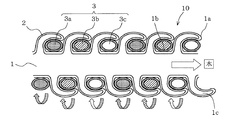
図1は本発明の実施形態に係る捩り管形熱交換器の内管軸線方向に沿う断面図である。本発明の実施形態に係る捩り管形熱交換器10は、図1のように複数条(例えば3条)の螺旋山1aと螺旋溝1bを持つ芯管となる内管すなわち水管1と、螺旋溝1bに沿うように巻き付けた複数条の外管すなわち冷媒管3a,3b,3c(これらをまとめて「冷媒管3」という場合もある)と、を備えている。
FIG. 1 is a cross-sectional view of the twisted tube heat exchanger according to the embodiment of the present invention along the inner tube axis direction. As shown in FIG. 1, a torsion
これを更に詳述すると、水管1は、螺旋山1aの高さが螺旋溝1bに巻きつけた冷媒管3a,3b,3cよりも高く、かつこの螺旋山1aの内部に流路となる空洞1cが残るように隣接する一方の冷媒管を包み込むようにカシメられて接合されている。このように、水管1に複数条の螺旋山1aと螺旋溝1bを設けることにより、冷媒管を冷媒管3a,3b,3c等に分岐してパス設計を最適化できるとともに、隣接する冷媒管相互の接触による熱漏洩を防止できる。また、カシメ接合によって冷媒管3が固定化されるので、冷媒管3の内圧疲労に対して有利となり、冷媒管3そのものの薄肉化が可能となる。
More specifically, the water pipe 1 is higher in the height of the spiral mountain 1a than the
水管1は、燐脱酸銅平滑管の両端を固定し、内径側にマンドレルを挿入して連続的に捩り加工を加えながら、複数条の螺旋山1aと螺旋溝1bを形成することで、作成される。このとき、水管1のスパイラルピッチP(図4)を精度よく制御することで、冷媒管3が健全に嵌め込まれる。
The water pipe 1 is formed by fixing the both ends of a phosphorous deoxidized copper smooth pipe, inserting a mandrel on the inner diameter side and continuously twisting it to form a plurality of spiral ridges 1a and
冷媒管3は、熱交換器の入口側で入口ヘッダにより冷媒管3a,3b,3cに分流され、熱交換器の出口側で出口ヘッダにより合流される。冷媒管3は図示しない冷媒回路と接続され冷媒を循環させている。水管1も、捩り管形熱交換器10が収納されている装置の外部にある図示しない装置と接続され、捩り管形熱交換器10と外部の装置との間で水を循環させている。
The
水管1は、捩り管形熱交換器10が収納されている装置の外部へ取り出すための接続口やバルブを延長した配管に取り付けられる。一般的に、ヒートポンプ式給湯機の管や配管に接続する部品には、熱伝導率が良く、ロウ付けや曲げ加工が容易にできるリン脱酸銅管が使用される。
The water pipe 1 is attached to a pipe extending a connection port and a valve for taking it out of the apparatus in which the torsion
図2は図1の要部を拡大して示す断面図である。水管1の螺旋山1aのカシメ接合後における水管放射方向の冷媒管径Raは、水管1の螺旋山1aのカシメ接合前の段階における水管放射方向の冷媒管径Ro(図4)に比べて小さくなっている。これは、カシメ接合時に、水管1の螺旋山1aと螺旋溝1bとの間に冷媒管3が挟まれて圧縮され、断面扁平管状に変形されるためである。したがって、水管放射方向の冷媒管径Raは、断面扁平管状の短軸側外径を示している。水管1は、この断面扁平管状の短軸側外径Raが、カシメ接合前の螺旋山1aの高さHの1/2以下に形成されている。これによって、冷媒管3は、水管1の螺旋溝1b及び螺旋山1a側面との接触面積が増大し、伝熱性能を向上させることができる。
FIG. 2 is an enlarged cross-sectional view showing a main part of FIG. The refrigerant pipe diameter Ra in the water pipe radial direction after the caulking joint of the spiral mountain 1a of the water pipe 1 is smaller than the refrigerant pipe diameter Ro (FIG. 4) in the water pipe radial direction in the stage before the caulking joint of the helical mountain 1a of the water pipe 1. It has become. This is because at the time of caulking and joining, the
冷媒管3は、その外径、肉厚が、冷媒等の圧力に耐えるべく設計されている。冷媒管3は、通常、真円もしくは許容される扁平度を保有しないと、運転時の冷媒圧力により疲労破壊してしまう。本発明の捩り管形熱交換器10は、水管1の螺旋山1aのカシメ接合によって冷媒管3が螺旋山1aと螺旋溝1bとの間に包み込まれるように挟まれて保持されているので、冷媒管3の疲労耐力が向上しており、冷媒管3の扁平度が上がっても疲労破壊してしまうことがなくなる。また、あえて扁平させた冷媒管を使用することで、伝熱面積の拡大が期待できる。更に、冷媒管3の扁平度が有る程度許容できるため、冷媒管3の肉厚をより薄くすることが可能となる。
The
図3は本発明の実施形態に係る捩り管形熱交換器のカシメ接合前の状態を示す内管軸線方向に沿う断面図である。水管1は、そのスパイラル外径SRoが、そのスパイラル内径SRiの1.5倍以上となるように形成されている。これによって、水の流速を確保した上で冷媒管3を螺旋状に巻きつけて嵌め込むのに好適な水管1外周の螺旋山1a、螺旋溝1bを形成することができる。
FIG. 3 is a cross-sectional view along the axial direction of the inner tube showing a state before caulking and joining of the torsion tube heat exchanger according to the embodiment of the present invention. The water pipe 1 is formed such that its spiral outer diameter SRo is 1.5 times or more of its spiral inner diameter SRi. As a result, it is possible to form the spiral crest 1a and the
図4は図3の要部を拡大して示す断面図である。カシメ接合可能とするべく、水管1は、カシメ接合前の外周の螺旋山1aの高さHが、冷媒管3の外径Roの略2倍となるように形成してある。これにより、水管1の螺旋山1aを変形させカシメ接合する場合、冷媒管3と十分に接触させることが可能となり、かつ隣接しあう螺旋山1aへの接触を避けることが可能となる。
FIG. 4 is an enlarged cross-sectional view showing a main part of FIG. In order to enable caulking and joining, the water pipe 1 is formed such that the height H of the outer peripheral spiral mountain 1a before caulking is approximately twice the outer diameter Ro of the
水管1の外周の螺旋山1aの高さHが冷媒管3の外径Roの2倍よりも小さい場合、冷媒管3との接触面積が十分には稼げず、伝熱性能が低下する。また、水管1の外周の螺旋山1aの高さHが冷媒管3の外径Roの2倍よりも大きい場合、カシメ時に隣接する螺旋山1aの側面に衝突し、冷媒管2とのカシメが十分でなくなるため、同じく伝熱性能が低下する。
When the height H of the spiral mountain 1a on the outer periphery of the water pipe 1 is smaller than twice the outer diameter Ro of the
水管1は、そのスパイラルピッチPが、冷媒管3の直径Roより大きく、冷媒管3の直径Roの2倍より小さくなるように形成されている。このように、水管1の外周に特定範囲のピッチで特定範囲の山高さを設けた螺旋山1a及び螺旋溝1bに沿って冷媒管3を巻きつけるので、螺旋山1a及び螺旋溝1bがガイドとなって冷媒管3を所定の位置に容易にかつ安定して巻きつけて嵌め込み、固定することが可能となる。
The water pipe 1 is formed such that its spiral pitch P is larger than the diameter Ro of the
以上のように、本発明の実施形態に係る捩り管形熱交換器は、外周に複数条の螺旋山1a及び螺旋溝1bを各条毎に連続して螺旋状に設けた水管1と、この水管外周の螺旋山1a及び螺旋溝1bの形状に沿って螺旋状に巻きつけた複数条の冷媒管3とを備え、冷媒管3を水管1の螺旋山1a及び螺旋溝1bに嵌め込んだ後、水管1の螺旋山1aを、内部に流路となる空洞1cが残るように各冷媒管3の軸線を挟む一方の側よりカシメて、各冷媒管3を包み込むように接合しているので、金属ロウによる接合材を使用することなく、水管1と冷媒管3を密着接合でき、安価に製造することができる。また、水管1のカシメた部分も流路となるので、内部を流れる流体の乱流効果を期待することができ、伝熱性能を向上させることができる。
As described above, the torsion tube heat exchanger according to the embodiment of the present invention includes a water tube 1 in which a plurality of spiral ridges 1a and
更に、カシメ接合することで、冷媒管3を固定化することができ、疲労耐圧に対し肉厚に余裕ができ、冷媒管3の薄肉化が可能となる。
Further, the caulking and joining can fix the
1 水管(芯管となる内管)、1a 螺旋山、1b 螺旋溝、1c 空洞、3,3a,3b,3c 冷媒管(外管)、10 捩り管形熱交換器、H 水管の螺旋山高さ、P 水管のスパイラルピッチ、Ra 冷媒管短軸側外径、Ro 冷媒管の外径、SRo 水管のスパイラル外径、SRi 水管のスパイラル内径。 DESCRIPTION OF SYMBOLS 1 Water pipe (inner pipe used as a core pipe), 1a Spiral crest, 1b Spiral groove, 1c Cavity, 3, 3a, 3b, 3c Refrigerant pipe (outer pipe), 10 Torsion pipe type heat exchanger, H Spiral crest height of water pipe , P Spiral pitch of water pipe, Ra refrigerant pipe minor axis outer diameter, Ro refrigerant pipe outer diameter, SRo water pipe spiral outer diameter, SRi water pipe spiral inner diameter.
Claims (4)
前記内管の螺旋溝に沿うように巻きつけた複数条の外管とを備え、
前記螺旋山の高さが前記螺旋溝に巻きつけた前記外管よりも高く、かつ該螺旋山は該螺旋山に隣接する一方の外管を包み込むようにカシメられており、該一方の外管を包み込んでいる該螺旋山の内部に流路となる空洞が残っていることを特徴とする捩り管形熱交換器。 An inner pipe having a plurality of spiral mountains and spiral grooves on the outer peripheral surface;
A plurality of outer tubes wound around the spiral groove of the inner tube,
Before Symbol higher than the outer tube the height of the spiral pile is wound on the helical groove, and the helical mountains is caulked so as to wrap one outer tube adjacent the helical mountains, the one out of A twisted tube heat exchanger characterized in that a cavity serving as a flow path remains inside the spiral mountain surrounding the tube .
Priority Applications (1)
| Application Number | Priority Date | Filing Date | Title |
|---|---|---|---|
| JP2012133588A JP5794952B2 (en) | 2012-06-13 | 2012-06-13 | Twisted tube heat exchanger |
Applications Claiming Priority (1)
| Application Number | Priority Date | Filing Date | Title |
|---|---|---|---|
| JP2012133588A JP5794952B2 (en) | 2012-06-13 | 2012-06-13 | Twisted tube heat exchanger |
Publications (3)
| Publication Number | Publication Date |
|---|---|
| JP2013257078A JP2013257078A (en) | 2013-12-26 |
| JP2013257078A5 JP2013257078A5 (en) | 2014-07-24 |
| JP5794952B2 true JP5794952B2 (en) | 2015-10-14 |
Family
ID=49953661
Family Applications (1)
| Application Number | Title | Priority Date | Filing Date |
|---|---|---|---|
| JP2012133588A Expired - Fee Related JP5794952B2 (en) | 2012-06-13 | 2012-06-13 | Twisted tube heat exchanger |
Country Status (1)
| Country | Link |
|---|---|
| JP (1) | JP5794952B2 (en) |
Families Citing this family (1)
| Publication number | Priority date | Publication date | Assignee | Title |
|---|---|---|---|---|
| WO2014199479A1 (en) * | 2013-06-13 | 2014-12-18 | 三菱電機株式会社 | Heat pump device |
Family Cites Families (2)
| Publication number | Priority date | Publication date | Assignee | Title |
|---|---|---|---|---|
| JP4084174B2 (en) * | 2002-12-10 | 2008-04-30 | 松下電器産業株式会社 | Heat exchanger |
| JP5255236B2 (en) * | 2007-06-25 | 2013-08-07 | 古河電気工業株式会社 | Heat exchanger and heat exchange system |
-
2012
- 2012-06-13 JP JP2012133588A patent/JP5794952B2/en not_active Expired - Fee Related
Also Published As
| Publication number | Publication date |
|---|---|
| JP2013257078A (en) | 2013-12-26 |
Similar Documents
| Publication | Publication Date | Title |
|---|---|---|
| JP3953074B2 (en) | Heat exchanger | |
| JP4449856B2 (en) | Twisted tube heat exchanger | |
| US20150300745A1 (en) | Counterflow helical heat exchanger | |
| JP4211041B2 (en) | Heat pump water heater | |
| JP4932439B2 (en) | Plate fin tube heat exchanger and manufacturing method thereof | |
| JP4819765B2 (en) | Method for manufacturing twisted tube heat exchanger | |
| JP2005164166A (en) | Heat exchanger | |
| JP4084174B2 (en) | Heat exchanger | |
| JP4224793B2 (en) | Heat exchanger and manufacturing method thereof | |
| JP5794952B2 (en) | Twisted tube heat exchanger | |
| JP5935763B2 (en) | Twisted tube heat exchanger and manufacturing method of torsion tube heat exchanger | |
| JP5404589B2 (en) | Twisted tube heat exchanger | |
| JP6005612B2 (en) | Heat exchanger for air conditioning equipment | |
| JP5289088B2 (en) | Heat exchanger and heat transfer tube | |
| JP2011163655A (en) | Method of manufacturing torsion pipe type heat exchanger and the torsion pipe type heat exchanger manufactured in the manufacturing method | |
| JP2010091266A (en) | Twisted tube type heat exchanger | |
| JP5656786B2 (en) | Manufacturing method of different diameter twisted tube heat exchanger | |
| JP4713562B2 (en) | Heat exchanger and heat pump water heater using the same | |
| JP2008107013A (en) | Heat transfer tube having leakage detecting mechanism and heat exchanger using the same | |
| WO2012017777A1 (en) | Double pipe for heat exchanger | |
| JP4206712B2 (en) | Heat exchanger and manufacturing method thereof | |
| JP2012007771A (en) | Heat exchanger | |
| JP5661012B2 (en) | Twisted tube heat exchanger and method of manufacturing twisted tube heat exchanger | |
| JP5073074B2 (en) | Heat exchanger and heat pump water heater using the same | |
| JP6682017B2 (en) | Twist tube heat exchanger |
Legal Events
| Date | Code | Title | Description |
|---|---|---|---|
| A521 | Written amendment |
Free format text: JAPANESE INTERMEDIATE CODE: A523 Effective date: 20140606 |
|
| A621 | Written request for application examination |
Free format text: JAPANESE INTERMEDIATE CODE: A621 Effective date: 20140606 |
|
| A977 | Report on retrieval |
Free format text: JAPANESE INTERMEDIATE CODE: A971007 Effective date: 20150219 |
|
| A131 | Notification of reasons for refusal |
Free format text: JAPANESE INTERMEDIATE CODE: A131 Effective date: 20150331 |
|
| A521 | Written amendment |
Free format text: JAPANESE INTERMEDIATE CODE: A523 Effective date: 20150529 |
|
| TRDD | Decision of grant or rejection written | ||
| A01 | Written decision to grant a patent or to grant a registration (utility model) |
Free format text: JAPANESE INTERMEDIATE CODE: A01 Effective date: 20150714 |
|
| A61 | First payment of annual fees (during grant procedure) |
Free format text: JAPANESE INTERMEDIATE CODE: A61 Effective date: 20150811 |
|
| R150 | Certificate of patent or registration of utility model |
Ref document number: 5794952 Country of ref document: JP Free format text: JAPANESE INTERMEDIATE CODE: R150 |
|
| R250 | Receipt of annual fees |
Free format text: JAPANESE INTERMEDIATE CODE: R250 |
|
| R250 | Receipt of annual fees |
Free format text: JAPANESE INTERMEDIATE CODE: R250 |
|
| LAPS | Cancellation because of no payment of annual fees |