WO2014196514A1 - 血管異常検知装置 - Google Patents
血管異常検知装置 Download PDFInfo
- Publication number
- WO2014196514A1 WO2014196514A1 PCT/JP2014/064691 JP2014064691W WO2014196514A1 WO 2014196514 A1 WO2014196514 A1 WO 2014196514A1 JP 2014064691 W JP2014064691 W JP 2014064691W WO 2014196514 A1 WO2014196514 A1 WO 2014196514A1
- Authority
- WO
- WIPO (PCT)
- Prior art keywords
- pulse wave
- signal
- photoelectric pulse
- blood vessel
- peak
- Prior art date
- Legal status (The legal status is an assumption and is not a legal conclusion. Google has not performed a legal analysis and makes no representation as to the accuracy of the status listed.)
- Ceased
Links
Images





Classifications
-
- A—HUMAN NECESSITIES
- A61—MEDICAL OR VETERINARY SCIENCE; HYGIENE
- A61B—DIAGNOSIS; SURGERY; IDENTIFICATION
- A61B5/00—Measuring for diagnostic purposes; Identification of persons
- A61B5/02—Detecting, measuring or recording for evaluating the cardiovascular system, e.g. pulse, heart rate, blood pressure or blood flow
- A61B5/02007—Evaluating blood vessel condition, e.g. elasticity, compliance
-
- A—HUMAN NECESSITIES
- A61—MEDICAL OR VETERINARY SCIENCE; HYGIENE
- A61B—DIAGNOSIS; SURGERY; IDENTIFICATION
- A61B5/00—Measuring for diagnostic purposes; Identification of persons
- A61B5/0059—Measuring for diagnostic purposes; Identification of persons using light, e.g. diagnosis by transillumination, diascopy, fluorescence
- A61B5/0082—Measuring for diagnostic purposes; Identification of persons using light, e.g. diagnosis by transillumination, diascopy, fluorescence adapted for particular medical purposes
-
- A—HUMAN NECESSITIES
- A61—MEDICAL OR VETERINARY SCIENCE; HYGIENE
- A61B—DIAGNOSIS; SURGERY; IDENTIFICATION
- A61B5/00—Measuring for diagnostic purposes; Identification of persons
- A61B5/02—Detecting, measuring or recording for evaluating the cardiovascular system, e.g. pulse, heart rate, blood pressure or blood flow
- A61B5/021—Measuring pressure in heart or blood vessels
- A61B5/02108—Measuring pressure in heart or blood vessels from analysis of pulse wave characteristics
- A61B5/02125—Measuring pressure in heart or blood vessels from analysis of pulse wave characteristics of pulse wave propagation time
-
- A—HUMAN NECESSITIES
- A61—MEDICAL OR VETERINARY SCIENCE; HYGIENE
- A61B—DIAGNOSIS; SURGERY; IDENTIFICATION
- A61B5/00—Measuring for diagnostic purposes; Identification of persons
- A61B5/02—Detecting, measuring or recording for evaluating the cardiovascular system, e.g. pulse, heart rate, blood pressure or blood flow
- A61B5/024—Measuring pulse rate or heart rate
- A61B5/0245—Measuring pulse rate or heart rate by using sensing means generating electric signals, i.e. ECG signals
-
- A—HUMAN NECESSITIES
- A61—MEDICAL OR VETERINARY SCIENCE; HYGIENE
- A61B—DIAGNOSIS; SURGERY; IDENTIFICATION
- A61B5/00—Measuring for diagnostic purposes; Identification of persons
- A61B5/145—Measuring characteristics of blood in vivo, e.g. gas concentration or pH-value ; Measuring characteristics of body fluids or tissues, e.g. interstitial fluid or cerebral tissue
- A61B5/1455—Measuring characteristics of blood in vivo, e.g. gas concentration or pH-value ; Measuring characteristics of body fluids or tissues, e.g. interstitial fluid or cerebral tissue using optical sensors, e.g. spectral photometrical oximeters
-
- A—HUMAN NECESSITIES
- A61—MEDICAL OR VETERINARY SCIENCE; HYGIENE
- A61B—DIAGNOSIS; SURGERY; IDENTIFICATION
- A61B5/00—Measuring for diagnostic purposes; Identification of persons
- A61B5/24—Detecting, measuring or recording bioelectric or biomagnetic signals of the body or parts thereof
- A61B5/316—Modalities, i.e. specific diagnostic methods
- A61B5/318—Heart-related electrical modalities, e.g. electrocardiography [ECG]
- A61B5/33—Heart-related electrical modalities, e.g. electrocardiography [ECG] specially adapted for cooperation with other devices
-
- A—HUMAN NECESSITIES
- A61—MEDICAL OR VETERINARY SCIENCE; HYGIENE
- A61B—DIAGNOSIS; SURGERY; IDENTIFICATION
- A61B5/00—Measuring for diagnostic purposes; Identification of persons
- A61B5/68—Arrangements of detecting, measuring or recording means, e.g. sensors, in relation to patient
- A61B5/6887—Arrangements of detecting, measuring or recording means, e.g. sensors, in relation to patient mounted on external non-worn devices, e.g. non-medical devices
-
- A—HUMAN NECESSITIES
- A61—MEDICAL OR VETERINARY SCIENCE; HYGIENE
- A61B—DIAGNOSIS; SURGERY; IDENTIFICATION
- A61B5/00—Measuring for diagnostic purposes; Identification of persons
- A61B5/68—Arrangements of detecting, measuring or recording means, e.g. sensors, in relation to patient
- A61B5/6887—Arrangements of detecting, measuring or recording means, e.g. sensors, in relation to patient mounted on external non-worn devices, e.g. non-medical devices
- A61B5/6895—Sport equipment
-
- A—HUMAN NECESSITIES
- A61—MEDICAL OR VETERINARY SCIENCE; HYGIENE
- A61B—DIAGNOSIS; SURGERY; IDENTIFICATION
- A61B5/00—Measuring for diagnostic purposes; Identification of persons
- A61B5/68—Arrangements of detecting, measuring or recording means, e.g. sensors, in relation to patient
- A61B5/6887—Arrangements of detecting, measuring or recording means, e.g. sensors, in relation to patient mounted on external non-worn devices, e.g. non-medical devices
- A61B5/6898—Portable consumer electronic devices, e.g. music players, telephones, tablet computers
-
- A—HUMAN NECESSITIES
- A61—MEDICAL OR VETERINARY SCIENCE; HYGIENE
- A61B—DIAGNOSIS; SURGERY; IDENTIFICATION
- A61B5/00—Measuring for diagnostic purposes; Identification of persons
- A61B5/72—Signal processing specially adapted for physiological signals or for diagnostic purposes
- A61B5/7235—Details of waveform analysis
Definitions
- the present invention relates to a blood vessel abnormality detection device, and more particularly to a blood vessel abnormality detection device that detects a blood vessel abnormality by measuring a pulse wave propagation time.
- pulse wave propagation speed increases with, for example, the progress of arteriosclerosis, and conversely, when there is arterial stenosis, it tends to be slower.
- a technique has been proposed in which the pulse wave velocity (or pulse wave propagation time) is applied to, for example, arteriosclerosis, arterial stenosis, aneurysm and other blood vessel failure diagnosis using such characteristics ( For example, see Patent Document 1).
- the pulse wave velocity is measured almost simultaneously in two different sections of the subject, that is, the first pulse wave velocity in the first section (for example, from the heart to the upper arm) and the first section.
- Measure the second pulse wave velocity in the second section for example, from the thigh to the ankle) different from, calculate the ratio of the two pulse wave velocity, and diagnose the vascular disorder based on the ratio
- a technique for diagnosing a vascular disorder is disclosed.
- the vascular disorder diagnosis apparatus described in Patent Document 1 is fixed on the chest of a subject, detects a heart sound that is a heartbeat synchronization signal in the heart (upstream end of the first section), and a right-hand arm.
- a cuff (upper arm pulse wave sensor) that is wound around the upper arm (downstream end of the first section) and detects a cuff pulse wave signal, that is, an upper arm pulse wave, is provided.
- this vascular disorder diagnostic apparatus is attached to the body surface of the thigh, and includes a first ultrasonic receiving probe that detects a thigh pulse wave as a heartbeat synchronization signal in the thigh (upstream end of the second section). And a second ultrasonic receiving probe that detects an ankle pulse wave as a heartbeat synchronization signal at the ankle (downstream end of the second section).
- the first pulse wave propagation velocity in the first section (between the heart and the upper arm) is measured based on the heart sound and the brachial pulse wave, and the femoral pulse wave Based on the ankle pulse wave, the second pulse wave propagation velocity in the second section (between the thigh and the ankle) is measured. Then, when the ratio between the first pulse wave velocity and the second pulse wave velocity is calculated, and the ratio is a value outside the normal range, it is diagnosed that there is a vascular disorder in the artery in one of the sections. Is done.
- the pulse wave velocity is measured substantially simultaneously in two different sections of the subject (between the heart and the upper arm, and between the thigh and the ankle)
- a vascular disorder can be diagnosed based on the ratio.
- this vascular disorder diagnosis apparatus it is necessary to include a heart sound microphone, a cuff, a first ultrasonic reception probe, and a second ultrasonic reception probe, and the apparatus becomes relatively large.
- a heart sound microphone is fixed on the chest, a cuff is wound around the upper arm, a first ultrasonic receiving probe is attached to the thigh, and a second ultrasonic receiving probe is used.
- a heart sound microphone is fixed on the chest
- a cuff is wound around the upper arm
- a first ultrasonic receiving probe is attached to the thigh
- a second ultrasonic receiving probe is used.
- the blood vessel failure diagnosis apparatus described in Patent Document 1 requires complicated preparation for measuring the pulse wave velocity, and also requires complicated and specialized knowledge such as measurement procedures and cuff operations. For this reason, the user cannot use it easily by himself / herself.
- the present invention has been made to solve the above-described problems, and provides a blood vessel abnormality detection apparatus that can be used by a user alone and that can more easily measure a pulse wave propagation time and detect a blood vessel abnormality.
- the purpose is to provide.
- a blood vessel abnormality detection device includes a pair of electrocardiographic electrodes for detecting an electrocardiographic signal, a light emitting element and a light receiving element, which are disposed in the vicinity of one of the electrocardiographic electrodes.
- a first photoelectric pulse wave sensor that detects a second photoelectric pulse wave signal that has a light emitting element and a light receiving element and is disposed in the vicinity of the other electrocardiographic electrode.
- the first pulse wave propagation time is obtained from the time difference between the peak of the electrocardiogram signal and the peak of the first photoelectric pulse wave signal, and the peak detection means for detecting the peak of each pulse wave signal.
- the operator who calculates the second pulse wave propagation time from the time difference from the peak of the two photoelectric pulse wave signals If, based on the time difference between the first pulse wave propagation time and the second pulse wave propagation time, characterized in that it comprises detecting means for detecting an abnormality of the blood vessels.
- an electrocardiogram signal and a photoelectric pulse wave signal can be acquired only by touching the user.
- the first photoelectric pulse wave sensor is disposed in the vicinity of one electrocardiographic electrode and the second photoelectric pulse wave sensor is disposed in the vicinity of the other electrocardiographic electrode. Touching the other ECG electrode and the second photoelectric pulse wave sensor with the other hand, the ECG signal, the first photoelectric pulse wave signal and the second photoelectric pulse wave sensor are touched. Pulse wave signals can be acquired simultaneously.
- the first pulse wave propagation time is obtained by bringing the body parts (for example, the left and right hands, the left and right legs, etc.) of the left and right bodies into contact with the electrocardiogram electrode and the photoelectric pulse wave sensor.
- the time difference between the second pulse wave propagation time and the second pulse wave propagation time is large, it can be determined that there is a possibility that there is an abnormality in the blood vessel of either the left half body or the right half body. Therefore, the user can use it alone, and it is possible to more easily measure the pulse wave propagation time and detect a blood vessel abnormality.
- pulse wave propagation time refers to the time during which a pulse wave propagates between two predetermined parts of a living body, and sometimes refers to the time difference between the peak of an electrocardiogram signal and the peak of the pulse wave signal.
- pulse wave propagation time is used in the latter sense.
- the pair of electrocardiographic electrodes, the first photoelectric pulse wave sensor, and the second photoelectric pulse wave sensor are in the same housing, and the user can move the housing with the left and right hands.
- the other hand is in contact with the other electrocardiographic electrode and the second photoelectric pulse wave sensor. It is preferable that it is attached to.
- the pulse wave propagation time of the right hand and the left hand can be acquired. Therefore, it is possible to detect an abnormality in a blood vessel from the aortic arch where the artery extending from the heart branches to the left arm and the right arm to the left and right hands. In this case, since the pulse wave propagation time can be measured simultaneously with the left and right hands, it is possible to suppress variations in the left and right pulse wave propagation times due to heart rate fluctuations and blood pressure fluctuations that affect the pulse wave propagation time. A blood vessel abnormality can be detected with high accuracy.
- a blood vessel abnormality detection device includes a pair of electrocardiogram electrodes that detect an electrocardiogram signal, an inversion means that reverses the polarity of the electrocardiogram signal detected by the electrocardiogram electrode,
- One photoelectric pulse wave sensor that is disposed and has a light emitting element and a light receiving element and detects a photoelectric pulse wave signal, an electrocardiogram signal, and a peak detection means for detecting each peak of the photoelectric pulse wave signal,
- the first pulse wave propagation time is obtained from the time difference between the peak of the non-inverted ECG signal whose polarity is not inverted and the peak of the photoelectric pulse signal, and the peak of the ECG signal and the photoelectric pulse signal whose polarity is inverted
- Computation means for obtaining the second pulse wave propagation time from the time difference from the peak and detection means for detecting an abnormality of the blood vessel based on the time difference between the first pulse wave propagation time and the second pulse wave propagation time It is characterized by.
- the blood vessel abnormality detection device can measure the first pulse wave propagation time and the second pulse wave propagation time with one photoelectric pulse wave sensor. That is, since the number of photoelectric pulse wave sensors that consume power can be reduced, the power consumption and cost of the apparatus can be reduced.
- the polarity of the electrocardiogram signal is reversed, that is, the R wave (peak) included in the electrocardiogram signal is reversed upside down. The peak can be detected correctly by reversing the polarity of the signal. Therefore, measurement of pulse wave propagation time and detection of blood vessel abnormality can be performed more accurately.
- the inverting means is a switch for exchanging an input signal from one electrocardiogram electrode and an input signal from the other electrocardiogram electrode.
- the polarity of the electrocardiogram signal can be reversed by the switch operation even when the portion in contact with the electrocardiogram electrode is reversed. Therefore, it is possible to correctly detect the peak of the electrocardiogram waveform.
- the blood vessel abnormality detection device further includes front and back detection means for detecting the surface of the housing facing the user, and the reversing means determines the polarity of the electrocardiogram signal according to the detection result by the front and back detection means. Is preferably reversed.
- the blood vessel abnormality detection device further comprises contact detection means for detecting the presence or absence of a user's contact, and the inversion means changes the polarity of the electrocardiogram signal according to the presence or absence of the contact detected by the contact detection means. Inversion is preferred.
- the blood vessel abnormality detection device has at least a pair of electrocardiographic electrodes for detecting an electrocardiogram signal, a light emitting element and a light receiving element, and detects a photoelectric pulse wave signal by being in contact with both hands and both feet.
- detecting means for detecting an abnormality of the blood vessel.
- the blood vessel abnormality detection device can acquire the pulse wave propagation times of the right hand, left hand, right foot, and left foot with a single measurement. Therefore, for example, abnormalities in blood vessels between the aortic arch and the left and right hands and abnormalities in blood vessels between the common iliac artery and the left and right feet can be detected at a time.
- the detection means automatically starts detecting a blood vessel abnormality when at least one of the conditions is satisfied among the payments of the compensation.
- the detection means automatically ends the detection of the blood vessel abnormality when a predetermined time has elapsed.
- the blood vessel abnormality detection device includes a presentation unit that automatically presents voice and / or image guidance when the detection of the blood vessel abnormality is started and / or when the detection of the blood vessel abnormality is finished. It is preferable to further provide.
- the user can be notified of the measurement state such as the start of measurement / detection and the end of measurement / detection.
- a user can use alone, and it is possible to more easily measure a pulse wave propagation time and detect a blood vessel abnormality.
- FIG. 1 is a block diagram illustrating a configuration of the blood vessel abnormality detection device 1.
- FIG. 2 is a diagram for explaining a method of using the vascular abnormality detection device 1.
- the blood vessel abnormality detection device 1 detects an electrocardiogram signal between the left and right hands, and a photoelectric pulse wave signal at the fingertip of the left hand and the fingertip of the right hand.
- the pulse wave propagation times of the left hand and the right hand are acquired from the time difference from the peak (rising point) of the wave signal (pulse wave).
- the vascular abnormality detection device 1 determines the left and right arms (between the aortic arch where the artery extending from the heart branches into the right arm and the left arm to the left and right hands) based on the difference between the acquired pulse wave propagation times. Detect abnormalities in blood vessels.
- the blood vessel abnormality detection device 1 mainly includes a pair of electrocardiogram electrodes (first electrocardiogram electrode 11 and second electrocardiogram electrode 12) for detecting an electrocardiogram signal between both hands, and photoelectric pulse waves of left and right hands.
- Two photoelectric pulse wave sensors (first photoelectric pulse wave sensor 21 and second photoelectric pulse wave sensor 22) for detecting signals (first photoelectric pulse wave signal and second photoelectric pulse wave signal) were detected.
- each component will be described in detail.
- the first electrocardiogram electrode 11 and the second electrocardiogram electrode 12 detect an electrocardiogram signal.
- the user holds the casing 5 of the blood vessel abnormality detection device 1 with both hands. Sometimes, for example, it is attached to the left and right side surfaces of the housing 5 so as to come into contact with the index finger. That is, when the user holds the casing 5 (blood vessel abnormality detection device 1), the first and second electrocardiographic electrodes 11 and 12 are brought into contact with the left and right hands (fingertips) of the user. An electrocardiogram signal corresponding to the potential difference between the left and right hands of the user is acquired.
- Examples of the electrode material of the first electrocardiogram electrode 11 and the second electrocardiogram electrode 12 include metals (preferably those that are resistant to corrosion such as stainless steel and Au and less metal allergy), conductive gels, conductive rubbers, conductive cloths, and the like. Preferably used.
- a conductive plastic, a capacitive coupling electrode or the like can be used as the electrode material of the first electrocardiogram electrode 11 and the second electrocardiogram electrode 12.
- Each of the first electrocardiogram electrode 11 and the second electrocardiogram electrode 12 is connected to the signal processing units 31 and 32 through a cable, and outputs an electrocardiogram signal to the signal processing units 31 and 32 through the cable. .
- the first and second photoelectric pulse wave sensors 21 and 22 are optical sensors for detecting a photoelectric pulse wave signal by utilizing the absorption characteristics of blood hemoglobin. Therefore, each of the first and second photoelectric pulse wave sensors 21 and 22 includes light emitting elements 211 and 221 and light receiving elements 212 and 222.
- the first photoelectric pulse wave sensor 21 that detects the first photoelectric pulse wave signal is disposed in the vicinity of one of the electrocardiographic electrodes 11 (for example, side by side).
- the second photoelectric pulse wave sensor 22 that detects the second photoelectric pulse wave signal is disposed in the vicinity of the other electrocardiographic electrode 12.
- the pair of first and second electrocardiographic electrodes 11, 12, the first photoelectric pulse wave sensor 21, and the second photoelectric pulse wave sensor 22 are in the same housing 5 and the user can use left and right hands.
- one hand for example, the left hand
- the light emitting elements 211 and 221 emit light according to a pulsed drive signal output from the drive unit 350 of the signal processing units 31 and 32.
- a pulsed drive signal output from the drive unit 350 of the signal processing units 31 and 32.
- the light emitting elements 211 and 221 for example, an LED, a VCSEL (Vertical Cavity Surface Emitting LASER), or a resonator type LED can be used.
- the driving unit 350 generates and outputs a pulsed driving signal for driving the light emitting element 211.
- the light receiving elements 212 and 222 are irradiated from the light emitting elements 211 and 221 and output detection signals corresponding to the intensity of light incident through the fingertip or reflected from the fingertip, for example.
- a photodiode or a phototransistor is preferably used as the light receiving elements 212 and 222.
- photodiodes are used as the light receiving elements 212 and 222.
- the light receiving elements 212 and 222 are connected to the signal processing units 31 and 32, and the detection signals (photoelectric pulse wave signals) obtained by the light receiving elements 212 and 222 are output to the signal processing units 31 and 32.
- each of the first electrocardiogram electrode 11, the second electrocardiogram electrode 12, and the first photoelectric pulse wave sensor 21 is connected to the signal processing unit 31, and the detected electrocardiogram signal and the first The photoelectric pulse wave signal is input to the signal processing unit 31.
- each of the first electrocardiogram electrode 11, the second electrocardiogram electrode 12, and the second photoelectric pulse wave sensor 22 is connected to the signal processing unit 32, and the detected electrocardiogram signal and the second photoelectric pulse wave sensor 22 are connected.
- a pulse wave signal is input to the signal processing unit 32.
- the signal processing unit 31 determines the first pulse wave propagation time (left hand) from the time difference between the R wave peak of the detected electrocardiogram signal (cardiac radio wave) and the peak (rising point) of the first photoelectric pulse wave signal (pulse wave). The pulse wave propagation time at the fingertip) is measured (see FIG. 3). Similarly, the signal processing unit 32 calculates the second pulse wave propagation time (pulse wave propagation time at the fingertip of the right hand) from the time difference between the detected R wave peak of the electrocardiogram signal and the peak of the second photoelectric pulse wave signal. measure. In addition, the signal processing units 31 and 32 process the input electrocardiogram signal and measure a heart rate, a heart beat interval, and the like.
- the signal processing units 31 and 32 process the input photoelectric pulse wave signal to measure the pulse rate, the pulse interval, and the like. Since the configuration of the signal processing unit 31 and the configuration of the signal processing unit 32 are the same, the signal processing unit 31 will be mainly described below.
- the signal processing unit 31 includes amplification units 311 and 321, a first signal processing unit 310, a second signal processing unit 320, peak detection units 316 and 326, peak correction units 318 and 328, and a pulse wave propagation time measurement unit. 330.
- the first signal processing unit 310 includes an analog filter 312, an A / D converter 313, and a digital filter 314.
- the second signal processing unit 320 includes an analog filter 322, an A / D converter 323, a digital filter 324, and a second-order differentiation processing unit 325.
- the digital filter 314, 324, the second-order differentiation processing unit 325, the peak detection units 316, 326, the peak correction units 318, 328, and the pulse wave propagation time measurement unit 330 are CPUs that perform arithmetic processing.
- a ROM for storing a program and data for causing the CPU to execute each process, a RAM for temporarily storing various data such as calculation results, and the like are included. That is, the functions of the above-described units are realized by executing the program stored in the ROM by the CPU.
- the amplification unit 311 is configured by an amplifier using an operational amplifier, for example, and amplifies the electrocardiogram signals detected by the first electrocardiogram electrode 11 and the second electrocardiogram electrode 12.
- the electrocardiographic signal amplified by the amplifying unit 311 is output to the first signal processing unit 310.
- the amplification unit 321 is configured by an amplifier using an operational amplifier, for example, and amplifies the first (second) photoelectric pulse wave signal detected by the first (second) photoelectric pulse wave sensor 21 (22). .
- the photoelectric pulse wave signal amplified by the amplification unit 321 is output to the second signal processing unit 320.
- the first signal processing unit 310 includes the analog filter 312, the A / D converter 313, and the digital filter 314, and performs filtering processing on the electrocardiogram signal amplified by the amplification unit 311. This extracts the pulsation component.
- the second signal processing unit 320 includes the analog filter 322, the A / D converter 323, the digital filter 324, and the second-order differentiation processing unit 325, and the first signal amplified by the amplification unit 321.
- a pulsation component is extracted by applying filtering processing and second-order differentiation processing to the photoelectric pulse wave signal.
- the analog filters 312 and 322 and the digital filters 314 and 324 remove components (noise) other than the frequency characterizing the electrocardiogram signal and the first (second) photoelectric pulse wave signal, and improve the S / N. Perform filtering. More specifically, a frequency component of 0.1 to 200 Hz is generally dominant for an electrocardiogram signal, and a frequency component of 0.1 to several tens of Hz is dominant for a photoelectric pulse wave signal.
- the S / N is improved by performing filtering using the analog filters 312 and 322 and the digital filters 314 and 324 and selectively passing only signals in the frequency range.
- the purpose is to extract only the pulsating component (that is, when it is not necessary to acquire a waveform or the like), a component other than the pulsating component by narrowing the pass frequency range to improve noise resistance. May be blocked.
- the analog filters 312, 322 and the digital filters 314, 324 are not necessarily provided, and only one of the analog filters 312, 322 and the digital filters 314, 324 may be provided. Note that the electrocardiogram signal subjected to the filtering process by the analog filter 312 and the digital filter 314 is output to the peak detection unit 316. Similarly, the first (second) photoelectric pulse wave signal filtered by the analog filter 322 and the digital filter 324 is output to the second-order differentiation processing unit 325.
- the second-order differential processing unit 325 obtains a second-order differential pulse wave (acceleration pulse wave) signal by performing second-order differentiation on the first (second) photoelectric pulse wave signal.
- the acquired acceleration pulse wave signal is output to the peak detector 326.
- the peak (rising point) of the photoelectric pulse wave is not clearly changed and may be difficult to detect. Therefore, it is preferable to detect the peak by converting it to an acceleration pulse wave.
- a second-order differential processing unit 325 is provided. Is not essential and may be omitted.
- the peak detection unit 316 detects the peak (R wave) of the electrocardiogram signal that has been subjected to signal processing by the first signal processing unit 310 (the pulsating component has been extracted).
- the peak detector 326 detects the peak (rising point) of the first (second) photoelectric pulse wave signal (acceleration pulse wave) that has been subjected to the filtering process by the second signal processor 320. That is, the peak detection units 316 and 326 function as peak detection means described in the claims.
- Each of the peak detection unit 316 and the peak detection unit 326 performs peak detection within the normal range of the heartbeat interval and the pulse interval, and information on the peak time, peak amplitude, and the like for all detected peaks is stored in the RAM or the like. save.
- the peak correction unit 318 obtains the delay time of the electrocardiogram signal in the first signal processing unit 310 (analog filter 312 and digital filter 314).
- the peak correction unit 318 corrects the peak of the electrocardiogram signal detected by the peak detection unit 316 based on the obtained delay time of the electrocardiogram signal.
- the peak correction unit 328 obtains the delay time of the photoelectric pulse wave signal in the second signal processing unit 320 (analog filter 322, digital filter 324, second-order differentiation processing unit 325).
- the peak correction unit 328 corrects the peak of the first (second) photoelectric pulse wave signal (acceleration pulse wave signal) detected by the peak detection unit 326 based on the obtained delay time of the photoelectric pulse wave signal.
- the corrected peak of the electrocardiogram signal and the corrected first (second) photoelectric pulse wave signal (acceleration pulse wave) are output to the pulse wave propagation time measurement unit 330. Note that providing the peak correction unit 318 is not essential and may be omitted.
- the pulse wave propagation time measurement unit 330 includes an R wave (peak) of the electrocardiogram signal corrected by the peak correction unit 318 and a first (second) photoelectric pulse wave signal (acceleration pulse wave) corrected by the peak correction unit 328. ) To determine the first (second) pulse wave propagation time from the interval (time difference) from the peak (rising point). That is, the pulse wave propagation time measurement unit 330 functions as a calculation unit described in the claims.
- the pulse wave propagation time measuring unit 330 of the signal processing unit 31 acquires the first pulse wave propagation time, that is, the pulse wave propagation time at the fingertip of the left hand.
- the pulse wave propagation time measuring unit 330 of the signal processing unit 32 acquires the second pulse wave propagation time, that is, the pulse wave propagation time at the fingertip of the right hand.
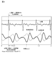
- FIG. 3 shows the pulse wave propagation time obtained from the interval between the R wave (peak) of the electrocardiogram signal and the peak of the first (second) photoelectric pulse wave signal (acceleration pulse wave).
- the waveform of the electrocardiogram signal is indicated by a thin solid line
- the first (second) photoelectric pulse wave signal is indicated by a broken line.
- the waveform of the acceleration pulse wave is shown by a thick solid line.
- the pulse wave propagation time measurement unit 330 calculates, for example, a heart rate, a heartbeat interval, a heartbeat interval change rate, and the like from an electrocardiogram signal. Similarly, the pulse wave propagation time measurement unit 330 calculates a pulse rate, a pulse interval, a pulse interval change rate, and the like from the photoelectric pulse wave signal (acceleration pulse wave).
- the signal processing units 31 and 32 output the first and second pulse wave propagation times acquired by the pulse wave propagation time measurement unit 330 to the detection unit 40.
- the detection unit 40 Based on the time difference between the first pulse wave propagation time (pulse wave propagation time at the fingertip of the left hand) and the second pulse wave propagation time (pulse wave propagation time at the fingertip of the right hand), the detection unit 40 Detect abnormalities in blood vessels (from the aortic arch to the left and right hands (fingertips)). That is, the detection unit 40 functions as a detection unit described in the claims.
- the pulse wave propagation time calculated from the peak of the photoelectric pulse wave at the electrocardiogram and fingertip is usually 0.1 to 0.3 sec. Indicates the degree value.
- the detection unit 40 calculates the time difference between the acquired first and second pulse wave propagation times of the left and right hands as a blood vessel abnormality due to the difference between the left and right hand pulse wave propagation times stored in the memory in advance. Compared with a suspected range, if it is out of range, it is determined that the blood vessel is abnormal. In addition, the detection unit 40 compares the calculated first and second pulse wave propagation times with a range of suspected vascular abnormalities of the pulse wave propagation time stored in advance in the memory, and when the result is out of range. Judged as vascular abnormality. Since the pulse wave propagation time is affected by the arm length, blood pressure, and heart rate, the above judgment is made by inputting the arm length, blood pressure, and heart rate of the user (measured person) before measurement. A function for correcting the reference range may be added.
- the calculated pulse wave propagation time, heart rate, heart rate interval, pulse rate, pulse interval, cardiac radio wave, photoelectric pulse wave, and acceleration Measurement data such as a pulse wave is output to the display unit 50 and the like.
- the acquired measurement data such as the pulse wave propagation time, heart rate, and pulse rate are accumulated and stored in, for example, the above-described RAM and the like and stored in a personal computer (PC) after the measurement is completed. You may make it output and confirm.
- PC personal computer
- the display unit 50 includes, for example, a liquid crystal display (LCD) or the like, and displays the detected blood vessel abnormality information and measurement data (measurement results) such as the acquired pulse wave transmission time, heart rate, and pulse rate in real time.
- the information may be transmitted to the PC, a portable music player having a display, a smartphone, or the like via the communication unit 60 and displayed. In this case, it is preferable to transmit data such as measurement date and time in addition to the measurement result and detection result.
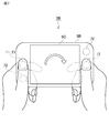
- FIG. 2 is a diagram for explaining a method of using the vascular abnormality detection device 1.
- an electrocardiogram signal between both hands, a first photoelectric pulse wave signal at the fingertip of the left hand, and a second photoelectric pulse wave signal at the fingertip of the right hand are acquired.
- the first pulse wave propagation time at the fingertip of the left hand and the second pulse wave propagation time at the fingertip of the right hand are acquired.
- a blood vessel abnormality is detected from the time difference between the first pulse wave propagation time and the second pulse wave propagation time.
- a blood vessel abnormality between the aortic arch where the artery extending from the heart branches into the right arm and the left arm and the left and right hands is detected.
- the user grasps the housing 5 (blood vessel abnormality detection device 1), touches the first electrocardiogram electrode 11 and the first photoelectric pulse wave sensor 21 with the fingertip of the left hand, and the first fingertip with the fingertip of the right hand.
- the two electrocardiographic electrodes 12 and the second photoelectric pulse wave sensor 22 it is possible to detect a blood vessel abnormality.
- an electrocardiogram signal can be obtained only by touching the user.
- a photoelectric pulse wave signal can be acquired.
- the first photoelectric pulse wave sensor 21 is disposed in the vicinity of the first electrocardiogram electrode 11 and the second photoelectric pulse wave sensor 22 is disposed in the vicinity of the second electrocardiogram electrode 12, for example, Touching the first electrocardiogram electrode 11 and the first photoelectric pulse wave sensor 21 with one hand (left hand) and touching the second electrocardiogram electrode 12 and the second photoelectric pulse wave sensor 22 with the other hand (right hand), the heart The electric signal, the first photoelectric pulse wave signal, and the second photoelectric pulse wave signal can be acquired simultaneously.
- the pulse wave propagation times (first pulse wave propagation time and second pulse wave propagation time) of the left hand and the right hand can be acquired, the arteries extending from the heart are separated into the left arm and the right arm. It is possible to detect a blood vessel abnormality between the branching aortic arch and the left and right hands. Therefore, the user can use it alone, and it is possible to more easily measure the pulse wave propagation time and detect a blood vessel abnormality.
- the left and right pulse wave propagation times can be measured simultaneously with the left and right hands, the left and right pulse wave propagation times due to heart rate fluctuations and blood pressure fluctuations that affect the pulse wave propagation time can be measured. Variations can be suppressed, and abnormalities in blood vessels can be detected with higher accuracy.
- the blood vessel abnormality detection device 1 includes two photoelectric pulse wave sensors (a first photoelectric pulse wave sensor 21 and a second photoelectric pulse wave sensor 22), and photoelectric pulses of left and right hands (fingertips).
- Wave signal (first photoelectric pulse wave signal, second photoelectric pulse wave signal) was acquired at the same time, but one photoelectric pulse wave sensor (first photoelectric pulse wave sensor) arranged only at the location where the left or right hand of the user contacts A pulse wave sensor 21), a storage unit 340, and a changeover switch 70 that reverses the polarity of the electrocardiogram signal; After acquiring the signal, the apparatus can be changed, the second photoelectric pulse wave signal (second pulse wave propagation time) is acquired with the other hand (for example, the right hand), and the time difference between the two can be calculated.
- FIG. 4 is a block diagram illustrating a configuration of the blood vessel abnormality detection device 2 according to the second embodiment.
- the same or equivalent components as those in the first embodiment are denoted by the same reference numerals.
- the blood vessel abnormality detection device 2 detects a second photoelectric pulse wave sensor 22 that detects a second photoelectric pulse wave signal, and calculates a pulse wave propagation time (second pulse wave propagation time) based on the second photoelectric pulse wave signal. It differs from the blood vessel abnormality detection device 1 described above in that it does not include the signal processing unit 32 to measure.
- the blood vessel abnormality detection device 2 is different from the blood vessel abnormality detection device 1 in that it includes a switch 70 and a storage unit 340.
- Other configurations are the same as or similar to those of the blood vessel abnormality detection device 1 described above, and thus detailed description thereof is omitted here.
- the casing 5B of the blood vessel abnormality detection device 2 has a thin, substantially rectangular parallelepiped shape, and a display unit 50 is attached to the front and back surfaces thereof.
- the 1st electrocardiogram electrode 11 (and the 1st photoelectric pulse wave sensor 21) and the 2nd electrocardiogram electrode 12 are arrange
- the switch 70 is detected by the first and second electrocardiographic electrodes 11 and 12 by switching the input signal from the first electrocardiographic electrode 11 and the input signal from the second electrocardiographic electrode 12 to each other. Inverts the polarity of the ECG signal. That is, the switch 70 functions as the inverting means described in the claims.
- the storage unit 340 is composed of the above-described RAM or the like, and temporarily stores the pulse wave propagation time (first pulse wave propagation time) acquired based on the electrocardiogram signal and the first photoelectric pulse wave signal.
- the detection part 40 is the 1st pulse wave propagation time memorize
- the display units 50 are arranged on both the front and back surfaces of the blood vessel abnormality detection device 2, the display on the front side display unit 50 is turned off and the display on the back side display unit 50 is turned on in conjunction with the inversion of the electrocardiogram signal. To do.
- the user When detecting a blood vessel abnormality using the electrocardiogram signal measuring apparatus 2, the user holds the casing 5B (blood vessel abnormality detecting apparatus 2), and for example, the fingertip of the left hand is placed on the first electrocardiographic electrode 11 and the first electrocardiogram electrode 11. While making contact with the photoelectric pulse wave sensor 21, the fingertip of the right hand is in contact with the second electrocardiographic electrode 12. By doing so, an electrocardiogram signal between both hands (a non-inverted electrocardiogram signal whose polarity is not inverted) and a first photoelectric pulse wave signal at the fingertip of the left hand are acquired. Then, the first pulse wave propagation time at the fingertip of the left hand is acquired and stored in the storage unit 340.
- blood vessel abnormality detecting apparatus 2 the user holds the casing 5B (blood vessel abnormality detecting apparatus 2), and for example, the fingertip of the left hand is placed on the first electrocardiographic electrode 11 and the first electrocardiogram electrode 11. While making contact with the photoelectric pulse wave sensor 21, the fingertip of the right hand is in
- the case 5B blood vessel abnormality detection device 2
- the fingertip of the right hand is placed on the first electrocardiogram electrode 11 and the first photoelectric pulse wave sensor 21, and the fingertip of the left hand is in contact with the second electrocardiographic electrode 12.
- an electrocardiogram signal between the two hands an electrocardiogram signal with the polarity reversed
- a second photoelectric pulse wave signal at the fingertip of the right hand are acquired, and the second pulse wave propagation time is measured.
- a blood vessel abnormality is detected from the time difference between the first pulse wave propagation time stored in the storage unit 340 and the second pulse wave propagation time measured thereafter.
- a blood vessel abnormality between the aortic arch where the artery extending from the heart branches into the right arm and the left arm and the left and right hands is detected.
- the first pulse wave propagation time and the second pulse wave propagation time can be measured with one photoelectric pulse wave sensor 21. That is, since the number of photoelectric pulse wave sensors that consume power can be reduced, the power consumption and cost of the apparatus can be reduced.
- the polarity of the electrocardiogram signal is reversed. That is, the R wave (peak) included in the electrocardiogram signal is inverted upside down, but the peak can be detected correctly by inverting the polarity of the electrocardiogram signal. Therefore, measurement of pulse wave propagation time and detection of blood vessel abnormality can be performed more accurately.
- the polarity of the electrocardiogram signal can be reversed by a switch operation. Furthermore, according to the present embodiment, since the display of the display unit 50 is switched in conjunction with the inversion of the electrocardiogram signal, when the inversion of the electrocardiogram signal is not correctly performed when the casing 5B is turned over. Since the display unit 50 on the back surface is not turned on, it is possible to prevent measurement / detection errors due to the electrocardiogram signal not being inverted.
- the polarity of the electrocardiogram signal is switched by the operation of the switch 70.
- the polarity of the electrocardiogram signal may be automatically switched by detecting the gripping state of the housing 5B.
- FIG. 5 is a block diagram illustrating a configuration of the vascular abnormality detection device 2 according to a first modification of the second embodiment.
- the same or equivalent components as those in the second embodiment are denoted by the same reference numerals.
- the blood vessel abnormality detection device 2B includes a front / back detection unit 71 that detects a surface (that is, a surface facing upward) of the blood vessel abnormality detection device 2B (housing 5B) facing the user, and Instead of the switch 70 described above, it differs from the blood vessel abnormality detection device 2 described above in that it includes an inversion unit 315 that inverts the polarity of the electrocardiogram signal according to the detection result by the front / back detection unit 71.
- Other configurations are the same as or similar to those of the blood vessel abnormality detection device 2 described above, and thus detailed description thereof is omitted here.
- the front / back detection unit 71 for example, an acceleration sensor, an inclination sensor, an illuminance sensor, or the like can be used.
- the front / back detector 71 functions as a front / back detector described in the claims.
- the inversion unit 315 is disposed between the digital filter 314 and the peak detection unit 316, and inverts the polarity of the electrocardiogram signal according to the detection result by the front / back detection unit 71. That is, the heart wave is inverted upside down. That is, the reversing unit 315 functions as reversing means described in the claims. In this way, when the part of the living body (left and right hands) in contact with the first and second ECG electrodes 11 and 12 is reversed, the peak is correctly detected by reversing the polarity of the ECG signal. The pulse wave propagation time can be accurately measured.
- FIG. 7 is a figure for demonstrating the usage method of the vascular abnormality detection apparatus 2B which concerns on the 2nd modification of 2nd Embodiment.
- the blood vessel abnormality detection device 2B is rotated 180 ° and the right thumb is used.
- a second photoelectric pulse wave signal is measured.
- the gripping state of the housing 5B (the rotation state of the blood vessel abnormality detection device 2B) is detected by including a contact detection unit 72 that detects the presence or absence of the user's contact in place of the front / back detection unit 71 described above. (See FIG. 6).
- the contact detection unit 72 functions as contact detection means described in the claims.
- a proximity sensor, a pressure sensor, a switch, or the like can be used as the contact detection unit 72.
- the contact detection unit 72 detects the contact / proximity of the base of the thumb or the palm, thereby determining the gripping direction (holding) of the housing 5B and automatically generating an electrocardiogram signal.
- the display on the display unit 50 is rotated 180 ° (that is, upside down) in conjunction with the inversion of the electrocardiogram signal.
- the first electrocardiogram electrode 11, the second electrocardiogram electrode 12, the first photoelectric pulse wave sensor 21, and the second photoelectric pulse wave sensor 22 are provided, and the pulse wave propagation time from the fingertips of the left and right hands.
- both hands it is also possible to acquire the pulse wave propagation time of both feet and detect a blood vessel abnormality in both feet.
- FIG. 8 is a block diagram showing a configuration of the blood vessel abnormality detection device 3.
- FIG. 9 is a diagram showing an external appearance of the main body 6 constituting the vascular abnormality detection device 3.
- FIG. 10 is a diagram for explaining a method of using the vascular abnormality detection device 3. 8, 9, and 10, the same reference numerals are given to the same or equivalent components as in the first embodiment.
- the blood vessel abnormality detection device 3 includes an electrocardiogram electrode (third electrocardiogram electrode 13 and fourth electrocardiogram electrode 14) for detecting an electrocardiogram signal, and a left and right foot photoelectric pulse wave signal (third photoelectric pulse wave signal). , Four photoelectric pulse wave sensors (third photoelectric pulse wave sensor 23, fourth photoelectric pulse wave sensor 24) for detecting the fourth photoelectric pulse wave signal), the detected electrocardiogram signal and the third and fourth Signal processing units 33 and 34 for measuring pulse wave propagation times (third pulse wave propagation time and fourth pulse wave propagation time) in the left and right legs based on the photoelectric pulse wave signals of It further includes a detection unit 40B that detects a blood vessel abnormality between both hands and both feet based on the difference between the second pulse wave propagation time and the difference between the third pulse wave propagation time and the fourth pulse wave propagation time. This is different from the blood vessel abnormality detection device 1 described above. Other configurations are the same as or similar to those of the blood vessel abnormality detection device 1 described above, and thus detailed description thereof is omitted here.
- the blood vessel abnormality detection device 3 includes a main body 6 that is used by being placed on a floor surface or the like, and a grip-type measurement probe 7 that is electrically connected to the main body 6 by a cable 8 and that a user holds with both hands. ing.
- the first and second photoelectric pulse wave sensors 21, 22 and the first and second electrocardiographic electrodes 11, 12 are installed at the portions of the grip-type measurement probe 7 that are in contact with the left and right hands.
- the third and fourth photoelectric pulse wave sensors 23 and 24 and the third and fourth electrocardiographic electrodes 13 and 14 are disposed in portions of the main body 6 that are in contact with the left and right soles (note that The third electrocardiogram electrode 13 and the fourth electrocardiogram electrode 14 are short-circuited).
- the first to fourth photoelectric pulse wave sensors 21 to 24 By arranging the first to fourth photoelectric pulse wave sensors 21 to 24 in this way, photoelectric pulse wave signals are acquired by the left hand and the right hand, and the left sole and the right sole.
- the measurement site is preferably the palm or the ventral side of the big toe, but may be the forearm, the back of the foot, the lower leg, or the like.
- the first to fourth electrocardiographic electrodes 11 to 14 are arranged, so that an electrocardiographic signal is acquired between both hands or between one hand and the sole.
- the detection unit 40B includes an electrocardiogram signal measured between both hands, or between the hands and feet (especially when the electrocardiogram amplitude is small and cannot be measured stably between both hands), and the left foot, right foot, left hand, Measure the pulse wave propagation times of the left hand, right hand, left foot, and right foot from the photoelectric pulse wave signals measured with the right hand, respectively, the time difference between the pulse wave propagation times of the left hand and right hand, and the pulse of the left foot and right foot. From the time difference in wave propagation time, vascular abnormalities of the arm (from the aortic arch to the hand) and the leg (from the common iliac artery to the foot) are detected.
- the pulse wave propagation time calculated from the peak of the electrocardiogram signal and the peak of the photoelectric pulse wave signal on the sole is usually 0.1 to 0.4 sec. It becomes a value of about, and is larger than the value by hand. For this reason, also regarding the pulse wave propagation time of the foot, the range in which the blood vessel abnormality is suspected in the pulse wave propagation time alone and the range in which the blood vessel abnormality is suspected regarding the time difference between the pulse wave propagation times in the left and right legs (determination reference range) ) And stored in the storage unit 340 in advance.
- the detection unit 40B Based on a total of four pieces of data of the pulse wave propagation time of the left and right hands and the pulse wave propagation time of the left and right feet, the detection unit 40B performs vascular abnormality determination of a single body and a left-right difference.
- the pulse wave propagation time of the arm is affected by the length of the arm
- the pulse wave propagation time of the leg is affected by the length of the trunk and legs, blood pressure, and heart rate.
- a function of correcting the determination reference range by inputting the body data, blood pressure, and heart rate of the user (the person to be measured) may be added.
- the pulse wave propagation time of the left hand, the right hand, the left foot, and the right foot can be acquired by one measurement. Therefore, for example, abnormalities in blood vessels between the aortic arch and the left and right hands and abnormalities in blood vessels between the common iliac artery and the left and right feet can be detected at a time.
- an electrocardiogram signal, a first photoelectric pulse wave signal, and a second photoelectric pulse wave signal for a predetermined number of beats are acquired.
- the detection unit 40 automatically starts detecting a blood vessel abnormality.
- the detection unit 40 when an electrocardiogram signal, a first photoelectric pulse wave signal, and a second photoelectric pulse wave signal for a predetermined number of beats (for example, 30 beats) are acquired, and / or blood vessel abnormality When a predetermined time (for example, 30 seconds) elapses after the start of the detection, the detection unit 40 automatically ends the detection of the blood vessel abnormality.
- voice and / or image guidance is presented by the speaker 73 and the display unit 50 when the detection of the blood vessel abnormality is automatically started and / or when the detection of the blood vessel abnormality is finished. Is done. That is, the speaker 73 and the display unit 50 correspond to the presenting means described in the claims.
- the operation for starting the measurement / detection is unnecessary, so there is no occurrence of body motion noise that occurs with the start operation, and the comparison Measurement and detection in a quiet state is possible.
- the measurement / detection is automatically terminated. Therefore, the pulse wave propagation time can be measured more easily. It becomes possible to detect vascular abnormalities.
- the user can be notified of the measurement state such as the start of measurement / detection and the end of measurement / detection.
- the first and second electrocardiographic electrodes 11 and 12 and the first and second photoelectric pulse wave sensors 21 and 22 are brought into contact with the fingertips of both hands of the user. It may be an approximately target portion of the half body and the right half body, and instead of the fingertips of both hands, for example, the left and right palms, the forearm portion, the upper arm portion, and the like may be contacted.
- the first and second electrocardiographic electrodes 11 and 12 and the first photoelectric pulse wave sensor 21 are arranged on the upper surface of the housing 5B. You may arrange
- the third electrocardiogram electrode 13 and the fourth electrocardiogram electrode 14 for acquiring an electrocardiogram signal between both feet are provided, but the third electrocardiogram electrode 13 and the fourth electrocardiogram electrode 14 are omitted.
- a body composition meter function may be added to the blood vessel abnormality detection device 3 according to the third embodiment. In that case, since the electrocardiogram electrode can also be used as the measurement electrode of the body composition meter, a function can be added without greatly changing the mechanism design.
- the acquired measurement data such as heart rate and pulse rate may be output and displayed on a PC, a portable music player having a display, a smartphone, or the like.
- blood vessel abnormality determination or the like may be performed on the PC or smartphone side.
- it can also be set as the structure which transmits data to a server and processes on the server side.
- data such as the above-mentioned range of suspected vascular abnormalities of the pulse wave propagation time and the range of suspected vascular abnormalities of the difference between the pulse wave propagation times of the left and right arms are stored on the PC, smartphone, or server side.
Landscapes
- Health & Medical Sciences (AREA)
- Life Sciences & Earth Sciences (AREA)
- Engineering & Computer Science (AREA)
- Physics & Mathematics (AREA)
- Public Health (AREA)
- Surgery (AREA)
- Veterinary Medicine (AREA)
- General Health & Medical Sciences (AREA)
- Animal Behavior & Ethology (AREA)
- Biophysics (AREA)
- Pathology (AREA)
- Biomedical Technology (AREA)
- Heart & Thoracic Surgery (AREA)
- Medical Informatics (AREA)
- Molecular Biology (AREA)
- Cardiology (AREA)
- Physiology (AREA)
- Signal Processing (AREA)
- Vascular Medicine (AREA)
- Psychiatry (AREA)
- Computer Vision & Pattern Recognition (AREA)
- Artificial Intelligence (AREA)
- Multimedia (AREA)
- Spectroscopy & Molecular Physics (AREA)
- Optics & Photonics (AREA)
- Measuring Pulse, Heart Rate, Blood Pressure Or Blood Flow (AREA)
Abstract
血管異常検知装置(1)は、心電信号を検出する一対の心電電極(11,12)と、一方の心電電極(11)の近傍に配設され、第1の光電脈波信号を検出する第1光電脈波センサ(21)と、他方の心電電極(12)の近傍に配設され、第2の光電脈波信号を検出する第2光電脈波センサ(22)と、検出された心電信号、第1の光電脈波信号、及び第2の光電脈波信号それぞれのピークを検出するピーク部(316,326)と、心電信号のピークと第1の光電脈波信号のピークとの時間差から第1脈波伝播時間を求めるとともに、心電信号のピークと第2の光電脈波信号のピークとの時間差から第2脈波伝播時間を求める脈波伝播時間計測部(330)と、第1脈波伝播時間と第2脈波伝播時間との時間差に基づいて、血管の異常を検知する検知部(40)とを備える。
Description
本発明は、血管異常検知装置に関し、特に、脈波伝播時間を計測して血管異常を検知する血管異常検知装置に関する。
脈波が動脈内を伝播する速度(脈波伝播速度)は、例えば動脈硬化の進行に伴って速くなり、逆に、動脈狭窄があると遅くなる傾向が見られる。このような特性を利用し、近年、脈波伝播速度(又は脈波伝播時間)を、例えば、動脈硬化や、動脈狭窄、動脈瘤等の血管の障害診断に応用した技術が提案されている(例えば特許文献1参照)。ここで、特許文献1には、被験者の異なる2つの区間で略同時に脈波伝播速度を計測、すなわち、第1区間(例えば心臓から上腕部まで)の第1脈波伝播速度と、第1区間とは異なる第2区間(例えば大腿部から足首まで)の第2脈波伝播速度を計測して、その2つの脈波伝播速度の比を算出し、その比に基づいて、血管障害を診断する技術(血管障害診断装置)が開示されている。
より具体的には、特許文献1記載の血管障害診断装置は、被験者の胸部上に固着され、心臓(第1区間の上流端)における心拍同期信号である心音を検出する心音マイクと、右腕の上腕部(第1区間の下流端)に巻回され、カフ脈波信号すなわち上腕脈波を検出するカフ(上腕脈波センサ)とを備えている。また、この血管障害診断装置は、大腿部の体表面上に装着され、大腿部(第2区間の上流端)における心拍同期信号として、大腿脈波を検出する第1超音波受信プローブと、足首に装着され、足首(第2区間の下流端)における心拍同期信号として、足首脈波を検出する第2超音波受信プローブとを備えている。
上述した構成を有する特許文献1記載の血管障害診断装置では、心音と上腕脈波とに基づいて、第1区間(心臓-上腕部間)における第1脈波伝播速度が計測され、大腿脈波及び足首脈波に基づいて、第2区間(大腿部-足首間)における第2脈波伝播速度が計測される。そして、第1脈波伝播速度と第2脈波伝播速度との比が算出され、その比が正常範囲外の値である場合には、いずれか一方の区間の動脈に血管障害があると診断される。
上述したように、特許文献1に記載の血管障害診断装置によれば、被験者の異なる2つの区間(心臓-上腕部間、大腿部-足首間)で略同時に脈波伝播速度を計測し、その比に基づいて、血管障害を診断することができる。しかしながら、この血管障害診断装置では、心音マイク、カフ、第1超音波受信プローブ、及び、第2超音波受信プローブを備える必要があり、装置が比較的大型になる。また、脈波伝播速度を計測するためには、心音マイクを胸部上に固着し、カフを上腕部に巻回し、第1超音波受信プローブを大腿部に装着し、第2超音波受信プローブを足首に装着するとともに、これらを電子制御装置に接続する必要がある。
このように、特許文献1に記載の血管障害診断装置は、脈波伝播速度を計測するための準備が煩雑であり、また計測手順もカフの操作等、複雑で専門的な知識も必要になるため、ユーザが自分ひとりで手軽に使用できるものではない。
本発明は、上記問題点を解消する為になされたものであり、ユーザがひとりで使用でき、より簡便に脈波伝播時間を計測して血管異常を検知することが可能な血管異常検知装置を提供することを目的とする。
本発明に係る血管異常検知装置は、心電信号を検出する一対の心電電極と、一方の心電電極の近傍に配設され、発光素子と受光素子とを有し、第1の光電脈波信号を検出する第1光電脈波センサと、他方の心電電極の近傍に配設され、発光素子と受光素子とを有し、第2の光電脈波信号を検出する第2光電脈波センサと、一対の心電電極により検出された心電信号、第1光電脈波センサにより検出された第1の光電脈波信号、及び、第2光電脈波センサにより検出された第2の光電脈波信号それぞれのピークを検出するピーク検出手段と、心電信号のピークと第1の光電脈波信号のピークとの時間差から第1脈波伝播時間を求めるとともに、心電信号のピークと第2の光電脈波信号のピークとの時間差から第2脈波伝播時間を求める演算手段と、第1脈波伝播時間と第2脈波伝播時間との時間差に基づいて、血管の異常を検知する検知手段とを備えることを特徴とする。
本発明に係る血管異常検知装置によれば、心電電極、光電脈波センサを使用しているため、使用者が触れるだけで、心電信号、光電脈波信号を取得することができる。また、一方の心電電極の近傍に第1光電脈波センサが配設され、他方の心電電極の近傍に第2光電脈波センサが配設されているため、例えば、一方の手で一方の心電電極と第1光電脈波センサに触れ、他方の手で他方の心電電極と第2光電脈波センサに触れることにより、心電信号、第1光電脈波信号、及び第2光電脈波信号を同時に取得することができる。その際に、左半身と右半身の略左右対称な身体の部位(例えば左手と右手や、左足と右足等)を心電電極、光電脈波センサに接触させることにより、第1脈波伝播時間と第2脈波伝播時間との時間差が大きい場合には、左半身又は右半身いずれかの血管に異常がある可能性があると判定することができる。よって、ユーザがひとりで使用でき、より簡便に脈波伝播時間を計測して血管異常を検知することが可能となる。
なお、脈波伝播時間という用語は、生体の所定の2部位間を脈波が伝播する時間をさす場合と、心電信号のピークと脈波信号のピークとの時間差をいう場合とがあるが、本明細書では、以下、脈波伝播時間という用語を後者の意で用いる。
本発明に係る血管異常検知装置では、一対の心電電極、及び第1光電脈波センサ、第2光電脈波センサが、同一の筐体に、かつ、使用者が左右の手で該筐体を把持した際に、一方の手と、一方の心電電極、第1光電脈波センサとが接触し、他方の手と、他方の心電電極、第2光電脈波センサとが接触する位置に取り付けられていることが好ましい。
このようにすれば、右手と左手の脈波伝播時間を取得することができる。そのため、心臓から伸びる動脈が左腕と右腕とに分岐する大動脈弓から左右の手までの間の血管の異常を検知することができる。また、この場合、左右の手で同時に脈波伝播時間を計測できるため、脈波伝播時間に影響を与える心拍数変動や血圧変動による左右の脈波伝播時間のばらつきを抑制することができ、より精度よく血管の異常を検知することができる。
本発明に係る血管異常検知装置は、心電信号を検出する一対の心電電極と、心電電極により検出された心電信号の極性を反転させる反転手段と、一方の心電電極の近傍に配設され、発光素子と受光素子とを有し、光電脈波信号を検出する一つの光電脈波センサと、心電信号、及び、光電脈波信号それぞれのピークを検出するピーク検出手段と、極性が反転されていない非反転の心電信号のピークと光電脈波信号のピークとの時間差から第1脈波伝播時間を求めるとともに、極性が反転された心電信号のピークと光電脈波信号のピークとの時間差から第2脈波伝播時間を求める演算手段と、第1脈波伝播時間と第2脈波伝播時間との時間差に基づいて、血管の異常を検知する検知手段とを備えることを特徴とする。
本発明に係る血管異常検知装置によれば、1つの光電脈波センサで第1脈波伝播時間と第2脈波伝播時間を計測することができる。すなわち、電力を消費する光電脈波センサの数を削減することができるため、装置の低消費電力化、及び低コスト化を図ることができる。なお、心電電極を接触させる身体の部位が逆になった場合には、心電信号の極性が逆になる、すなわち心電信号に含まれるR波(ピーク)が上下逆転するが、心電信号の極性を反転させることでピークを正しく検出することができる。そのため、脈波伝播時間の計測、及び血管異常の検知をより正確に行うことができる。
本発明に係る血管異常検知装置では、反転手段が、一方の心電電極からの入力信号と、他方の心電電極からの入力信号とを互いに入替えるスイッチであることが好ましい。
このようにすれば、心電電極に接触する部位が逆になった場合であっても、スイッチ操作により心電信号の極性を反転することができる。よって、心電波形のピークを正しく検出することができる。
本発明に係る血管異常検知装置は、使用者と対向している筐体の面を検出する表裏検出手段をさらに備え、反転手段が、表裏検出手段による検出結果に応じて、心電信号の極性を反転させることが好ましい。
このようにすれば、使用者と対向している筐体の面(すなわち装置の裏表)が検知されることにより、使用者による装置の持ち替えを自動的に判定して、心電信号の極性を反転できるため、より簡易に血管の異常を検知することができる。
本発明に係る血管異常検知装置は、使用者の接触の有無を検出する接触検出手段をさらに備え、反転手段が、接触検出手段により検出された接触の有無に応じて、心電信号の極性を反転させることが好ましい。
このようにすれば、装置の把持状態が検知されることにより、使用者による装置の持ち替えを自動的に判定して、心電信号の極性を反転できるため、より簡易に血管の異常を検知することができる。
本発明に係る血管異常検知装置は、心電信号を検出する少なくとも一対の心電電極と、発光素子と受光素子とを有し、両手、両足に接触されて、光電脈波信号を検出する2対の光電脈波センサと、心電電極により検出された心電信号、及び、各光電脈波センサにより検出された各光電脈波信号それぞれのピークを検出するピーク検出手段と、心電信号のピークと各光電脈波信号それぞれのピークとの時間差から、各光電脈波信号に対応した脈波伝播時間を求める演算手段と、対を成す光電脈波センサに対応した脈波伝播時間同士の時間差に基づいて、血管の異常を検知する検知手段とを備えることを特徴とする。
本発明に係る血管異常検知装置によれば、一度の計測で、右手、左手、右足、左足の脈波伝播時間を取得することができる。そのため、例えば、大動脈弓から左右の手までの間の血管の異常、及び、総腸骨動脈から左右の足までの間の血管の異常を一度に検知することができる。
本発明に係る血管異常検知装置では、使用者の接触が検知されたとき、所定の拍数分の心電信号、第1の光電脈波信号、第2の光電脈波信号が取得されたとき、及び、対価が支払われたときのうち、少なくともいずれかの条件が満足されたときに、検知手段が、自動的に、血管異常の検知を開始することが好ましい。
このようにすれば、血管異常の検知が自動的に開始されるため、計測・検知を開始させるための動作が不要なため、開始動作に伴って発生する体動ノイズの発生がなく、比較的安静な状態での計測・検知が可能となる。
本発明に係る血管異常検知装置では、所定の拍数分の心電信号、第1の光電脈波信号、第2の光電脈波信号が取得されたとき、及び/又は、血管異常の検知開始後、所定時間が経過したときに、検知手段が、自動的に、血管異常の検知を終了することが好ましい。
このようにすれば、脈波伝播時間の計測・血管異常の検知が完了したときに、自動的に計測・検知が終了されるため、より簡易に、脈波伝播時間を計測して、血管異常を検知することが可能となる。
本発明に係る血管異常検知装置は、自動的に、血管異常の検知を開始する際、及び/又は、血管異常の検知を終了する際に、音声及び/又は画像によるガイダンスを提示する提示手段をさらに備えることが好ましい。
このようにすれば、使用者に、計測・検知の開始や、計測・検知の終了といった計測状態を知らせることができる。
本発明によれば、ユーザがひとりで使用でき、より簡便に脈波伝播時間を計測して血管異常を検知することが可能となる。
以下、図面を参照して本発明の好適な実施形態について詳細に説明する。なお、図中、同一又は相当部分には同一符号を用いることとする。また、各図において、同一要素には同一符号を付して重複する説明を省略する。
(第1実施形態)
まず、図1、図2を併せて用いて、第1実施形態に係る血管異常検知装置1の構成について説明する。図1は、血管異常検知装置1の構成を示すブロック図である。また、図2は、血管異常検知装置1の使用方法を説明するための図である。
まず、図1、図2を併せて用いて、第1実施形態に係る血管異常検知装置1の構成について説明する。図1は、血管異常検知装置1の構成を示すブロック図である。また、図2は、血管異常検知装置1の使用方法を説明するための図である。
血管異常検知装置1は、左右両手間の心電信号、及び、左手の指先並びに右手の指先での光電脈波信号を検出し、検出した心電信号(心電波)のR波ピークと光電脈波信号(脈波)のピーク(立ち上がり点)との時間差から左手及び右手それぞれの脈波伝播時間を取得する。そして、血管異常検知装置1は、取得した双方の脈波伝播時間の差に基づいて、左右の腕(心臓から伸びる動脈が右腕と左腕とに分岐する大動脈弓から左右の手までの間)の血管の異常を検知する。
そのため、血管異常検知装置1は、主として、両手間の心電信号を検出するための一対の心電電極(第1心電電極11、第2心電電極12)、左右の手の光電脈波信号(第1の光電脈波信号、第2の光電脈波信号)を検出するための2つの光電脈波センサ(第1光電脈波センサ21、第2光電脈波センサ22)、検出された心電信号及び第1,第2の光電脈波信号に基づいて左右の手における脈波伝播時間(第1脈波伝播時間、第2脈波伝播時間)を計測する信号処理部31,32、及び、第1脈波伝播時間と第2脈波伝播時間との差に基づいて血管の異常を検知する検知部40を備えている。以下、各構成要素について詳細に説明する。
第1心電電極11及び第2心電電極12は、心電信号を検出するものであり、図2に示されるように、使用者が血管異常検知装置1の筐体5を両手で把持したときに、例えば人差し指と接触するように、筐体5の左右の側面に取り付けられている。すなわち、使用者が筐体5(血管異常検知装置1)を把持したときに、第1心電電極11及び第2心電電極12は、使用者の左右の手(指先)が接触することにより、使用者の左右の手の間の電位差に応じた心電信号を取得する。第1心電電極11、第2心電電極12の電極材料としては、例えば、金属(ステンレス、Au等の腐食に強く金属アレルギーの少ないものが好ましい)や導電ゲル、導電ゴム、導電布等が好適に用いられる。その他、第1心電電極11、第2心電電極12の電極材料として、例えば、導電プラスチック、容量性結合電極等を用いることもできる。第1心電電極11及び第2心電電極12それぞれは、ケーブルを通して、信号処理部31,32と接続されており、該ケーブルを介して、心電信号を信号処理部31,32へ出力する。
第1,第2光電脈波センサ21,22は、血中ヘモグロビンの吸光特性を利用して、光電脈波信号を光学的に検出するセンサである。そのため、第1,第2光電脈波センサ21,22それぞれは、発光素子211,221と受光素子212,222とを含んで構成されている。ここで、第1の光電脈波信号を検出する第1光電脈波センサ21は、一方の心電電極11の近傍に(例えば横に並べて)配設されている。同様に、第2の光電脈波信号を検出する第2光電脈波センサ22は、他方の心電電極12の近傍に配設されている。すなわち、一対の第1,第2心電電極11,12、及び第1光電脈波センサ21、第2光電脈波センサ22は、同一の筐体5に、かつ、使用者が左右の手で該筐体5を把持した際に、一方の手(例えば左手)と第1心電電極11、第1光電脈波センサ21とが接触し、他方の手(例えば右手)と第2心電電極12、第2光電脈波センサ22とが接触する位置に取り付けられている。
発光素子211,221は、信号処理部31,32の駆動部350から出力されるパルス状の駆動信号に応じて発光する。発光素子211,221としては、例えば、LED、VCSEL(Vertical Cavity Surface Emitting LASER)、又は共振器型LED等を用いることができる。なお、駆動部350は、発光素子211を駆動するパルス状の駆動信号を生成して出力する。
受光素子212,222は、発光素子211,221から照射され、例えば指先を透過して、又は指先に反射して入射される光の強さに応じた検出信号を出力する。受光素子212,222としては、例えば、フォトダイオードやフォトトランジスタ等が好適に用いられる。本実施形態では、受光素子212,222として、フォトダイオードを用いた。受光素子212,222は、信号処理部31,32に接続されており、受光素子212,222で得られた検出信号(光電脈波信号)は信号処理部31,32に出力される。
上述したように、第1心電電極11、第2心電電極12、及び第1光電脈波センサ21それぞれは、信号処理部31に接続されており、検出された心電信号、及び第1の光電脈波信号が信号処理部31に入力される。同様に、第1心電電極11、第2心電電極12、及び第2光電脈波センサ22それぞれは、信号処理部32に接続されており、検出された心電信号、及び第2の光電脈波信号が信号処理部32に入力される。
信号処理部31は、検出した心電信号(心電波)のR波ピークと第1の光電脈波信号(脈波)のピーク(立ち上がり点)との時間差から第1脈波伝播時間(左手の指先での脈波伝播時間)を計測する(図3参照)。同様に、信号処理部32は、検出した心電信号のR波ピークと第2の光電脈波信号のピークとの時間差から第2脈波伝播時間(右手の指先での脈波伝播時間)を計測する。また、信号処理部31,32は、入力された心電信号を処理して、心拍数や心拍間隔などを計測する。さらに、信号処理部31,32は、入力された光電脈波信号を処理して、脈拍数や脈拍間隔などを計測する。なお、信号処理部31の構成と信号処理部32の構成とは、同一であるので、以下、信号処理部31を主にして説明する。
信号処理部31(32)は、増幅部311,321、第1信号処理部310、第2信号処理部320、ピーク検出部316,326、ピーク補正部318,328、及び脈波伝播時間計測部330を有している。また、上記第1信号処理部310は、アナログフィルタ312、A/Dコンバータ313、ディジタルフィルタ314を有している。一方、第2信号処理部320は、アナログフィルタ322、A/Dコンバータ323、ディジタルフィルタ324、2階微分処理部325を有している。
ここで、上述した各部の内、ディジタルフィルタ314,324、2階微分処理部325、ピーク検出部316,326、ピーク補正部318,328、脈波伝播時間計測部330は、演算処理を行うCPU、該CPUに各処理を実行させるためのプログラムやデータを記憶するROM、及び演算結果などの各種データを一時的に記憶するRAM等により構成されている。すなわち、ROMに記憶されているプログラムがCPUによって実行されることにより、上記各部の機能が実現される。
増幅部311は、例えばオペアンプ等を用いた増幅器により構成され、第1心電電極11、第2心電電極12により検出された心電信号を増幅する。増幅部311で増幅された心電信号は、第1信号処理部310に出力される。同様に、増幅部321は、例えばオペアンプ等を用いた増幅器により構成され、第1(第2)光電脈波センサ21(22)により検出された第1(第2)光電脈波信号を増幅する。増幅部321で増幅された光電脈波信号は、第2信号処理部320に出力される。
第1信号処理部310は、上述したように、アナログフィルタ312、A/Dコンバータ313、ディジタルフィルタ314を有しており、増幅部311で増幅された心電信号に対して、フィルタリング処理を施すことにより拍動成分を抽出する。
また、第2信号処理部320は、上述したように、アナログフィルタ322、A/Dコンバータ323、ディジタルフィルタ324、2階微分処理部325を有しており、増幅部321で増幅された第1(第2)光電脈波信号に対して、フィルタリング処理及び2階微分処理を施すことにより拍動成分を抽出する。
アナログフィルタ312,322、及び、ディジタルフィルタ314,324は、心電信号、第1(第2)光電脈波信号を特徴づける周波数以外の成分(ノイズ)を除去し、S/Nを向上するためのフィルタリングを行う。より詳細には、心電信号は一般的に0.1~200Hzの周波数成分、光電脈波信号は0.1~数十Hz付近の周波数成分が支配的であるため、ローパスフィルタやバンドパスフィルタ等のアナログフィルタ312,322、及びディジタルフィルタ314,324を用いてフィルタリング処理を施し、上記周波数範囲の信号のみを選択的に通過させることによりS/Nを向上する。
なお、拍動成分の抽出のみを目的とする場合(すなわち、波形等を取得する必要がない場合)には、ノイズ耐性を向上するために通過周波数範囲をより狭くして拍動成分以外の成分を遮断してもよい。また、アナログフィルタ312,322とディジタルフィルタ314,324は必ずしも両方備える必要はなく、アナログフィルタ312,322とディジタルフィルタ314,324のいずれか一方のみを設ける構成としてもよい。なお、アナログフィルタ312、ディジタルフィルタ314によりフィルタリング処理が施された心電信号は、ピーク検出部316へ出力される。同様に、アナログフィルタ322、ディジタルフィルタ324によりフィルタリング処理が施された第1(第2)光電脈波信号は、2階微分処理部325へ出力される。
2階微分処理部325は、第1(第2)光電脈波信号を2階微分することにより、2階微分脈波(加速度脈波)信号を取得する。取得された加速度脈波信号は、ピーク検出部326へ出力される。なお、光電脈波のピーク(立ち上がり点)は変化が明確でなく検出しにくいことがあるため、加速度脈波に変換してピーク検出を行うことが好ましいが、2階微分処理部325を設けることは必須ではなく、省略した構成としてもよい。
ピーク検出部316は、第1信号処理部310により信号処理が施された(拍動成分が抽出された)心電信号のピーク(R波)を検出する。一方、ピーク検出部326は、第2信号処理部320によりフィルタリング処理が施された第1(第2)光電脈波信号(加速度脈波)のピーク(立ち上がり点)を検出する。すなわち、ピーク検出部316,326は、請求の範囲に記載のピーク検出手段として機能する。なお、ピーク検出部316、及びピーク検出部326それぞれは、心拍間隔、及び脈拍間隔の正常範囲内においてピーク検出を行い、検出したすべてのピークについて、ピーク時間、ピーク振幅等の情報をRAM等に保存する。
ピーク補正部318は、第1信号処理部310(アナログフィルタ312、ディジタルフィルタ314)における心電信号の遅延時間を求める。ピーク補正部318は、求めた心電信号の遅延時間に基づいて、ピーク検出部316により検出された心電信号のピークを補正する。同様に、ピーク補正部328は、第2信号処理部320(アナログフィルタ322、ディジタルフィルタ324、2階微分処理部325)における光電脈波信号の遅延時間を求める。ピーク補正部328は、求めた光電脈波信号の遅延時間に基づいて、ピーク検出部326により検出された第1(第2)光電脈波信号(加速度脈波信号)のピークを補正する。補正後の心電信号のピーク、及び補正後の第1(第2)光電脈波信号(加速度脈波)のピークは、脈波伝播時間計測部330に出力される。なお、ピーク補正部318を設けることは必須ではなく、省略した構成としてもよい。
脈波伝播時間計測部330は、ピーク補正部318により補正された心電信号のR波(ピーク)と、ピーク補正部328により補正された第1(第2)光電脈波信号(加速度脈波)のピーク(立ち上がり点)との間隔(時間差)から第1(第2)脈波伝播時間を求める。すなわち、脈波伝播時間計測部330は、請求の範囲に記載の演算手段として機能する。ここで、信号処理部31の脈波伝播時間計測部330は、第1脈波伝播時間、すなわち左手の指先での脈波伝播時間を取得する。同様に、信号処理部32の脈波伝播時間計測部330は、第2脈波伝播時間、すなわち右手の指先での脈波伝播時間を取得する。ここで、心電信号のR波(ピーク)と第1(第2)光電脈波信号(加速度脈波)のピークとの間隔から求められる脈波伝播時間を図3に示す。なお、図3では、心電信号の波形を細い実線で示すとともに、第1(第2)光電脈波信号を破線で示した。また、加速度脈波の波形を太い実線で示した。
脈波伝播時間計測部330は、第1(第2)脈波伝播時間に加えて、例えば、心電信号から心拍数、心拍間隔、心拍間隔変化率等も算出する。同様に、脈波伝播時間計測部330は、光電脈波信号(加速度脈波)から脈拍数、脈拍間隔、脈拍間隔変化率等も算出する。信号処理部31,32は、脈波伝播時間計測部330で取得した第1,第2脈波伝播時間等を検知部40に出力する。
検知部40は、第1脈波伝播時間(左手の指先での脈波伝播時間)と第2脈波伝播時間(右手の指先での脈波伝播時間)との時間差に基づいて、左右の腕(大動脈弓から左右の手(指先)までの間)の血管の異常を検知する。すなわち、検知部40は、請求の範囲に記載の検知手段として機能する。ちなみに、心電と指先での光電脈波のピークから算出した脈波伝播時間は通常0.1~0.3sec.程度の値を示す。
より具体的には、検知部40は、取得した左右の手の第1,第2脈波伝播時間の時間差を、予めメモリに記憶されている左右の手の脈波伝播時間の差の血管異常が疑われる範囲と比較し、範囲外になった場合に血管異常と判定する。また、検知部40は、算出した第1,第2脈波伝播時間を、予めメモリに記憶されている脈波伝播時間単体の血管異常が疑われる範囲と比較し、範囲外になった場合に血管異常と判定する。なお、脈波伝播時間は腕の長さや、血圧、心拍数に影響を受けるため、計測の前に使用者(被測定者)の腕の長さや、血圧、心拍数を入力することで上記判定基準範囲を補正する機能を付加してもよい。
検知された血管異常情報(すなわち、血管異常の有無等の検知結果)をはじめ、算出された脈波伝播時間、心拍数、心拍間隔、脈拍数、脈拍間隔、心電波、光電脈波、及び加速度脈波等の計測データは、表示部50等に出力される。なお、取得された脈波伝播時間や、心拍数、脈拍数等の計測データは、例えば、上述したRAMなどに蓄積して記憶しておき、計測が終了した後に、パーソナルコンピュータ(PC)等に出力して確認するようにしてもよい。
表示部50は、例えば、液晶ディスプレイ(LCD)等からなり、検知された血管異常情報や、取得された脈波伝達時間、心拍数、脈拍数等の計測データ(計測結果)をリアルタイムに表示する。また、上記情報を、通信部60を介して、例えば、PCや、ディスプレイを有する携帯型音楽プレーヤ、又はスマートフォン等に送信して表示させる構成とすることもできる。なお、その場合には、測定結果や検知結果に加えて、測定日時等のデータも送信することが好ましい。
次に、図2を参照しつつ、血管異常検知装置1の使用方法について説明する。なお、図2は、血管異常検知装置1の使用方法を説明するための図である。心電信号計測装置1を用いて血管異常を検知する際には、まず、使用者が、筐体5(血管異常検知装置1)を両手で把持し、左手の指先を第1心電電極11及び第1光電脈波センサ21に接触させるとともに、右手の指先を第2心電電極12及び第2光電脈波センサ22に接触させる。
そうすることにより、両手間の心電信号、及び、左手の指先での第1の光電脈波信号、並びに右手の指先での第2の光電脈波信号が取得される。そして、左手の指先での第1脈波伝播時間、及び右手の指先での第2脈波伝播時間が取得される。なお、第1,第2第脈波伝播時間の取得方法については上述した通りであるので、ここでは詳細な説明を省略する。そして、第1脈波伝播時間と第2脈波伝播時間との時間差から血管異常が検知される。その結果、心臓から伸びる動脈が右腕と左腕とに分岐する大動脈弓から左右の手までの間の血管の異常が検知される。
このようにして、ユーザは、筐体5(血管異常検知装置1)を把持して、左手の指先で第1心電電極11及び第1光電脈波センサ21に触れるとともに、右手の指先で第2心電電極12及び第2光電脈波センサ22に触れるだけで、血管の異常を検知することができる。
以上、本実施形態によれば、第1,第2心電電極11,12、第1,第2光電脈波センサ21,22を使用しているため、使用者が触れるだけで、心電信号、光電脈波信号を取得することができる。また、第1心電電極11の近傍に第1光電脈波センサ21が配設され、第2心電電極12の近傍に第2光電脈波センサ22が配設されているため、例えば、一方の手(左手)で第1心電電極11と第1光電脈波センサ21に触れ、他方の手(右手)で第2心電電極12と第2光電脈波センサ22に触れることにより、心電信号、第1光電脈波信号、及び第2光電脈波信号を同時に取得することができる。特に、本実施形態によれば、左手と右手の脈波伝播時間(第1脈波伝播時間、第2脈波伝播時間)を取得することができるため、心臓から伸びる動脈が左腕と右腕とに分岐する大動脈弓から左右の手までの間の血管の異常を検知することができる。よって、ユーザがひとりで使用でき、より簡便に脈波伝播時間を計測して血管異常を検知することが可能となる。
また、本実施形態によれば、左右の手で同時に第1,第2脈波伝播時間を計測できるため、脈波伝播時間に影響を与える心拍数変動や血圧変動による左右の脈波伝播時間のばらつきを抑制することができ、より精度よく血管の異常を検知することができる。
(第2実施形態)
上述した第1実施形態に係る血管異常検知装置1では、2つの光電脈波センサ(第1光電脈波センサ21、第2光電脈波センサ22)を備え、左右の手(指先)の光電脈波信号(第1の光電脈波信号、第2の光電脈波信号)を同時に取得したが、使用者の左手又は右手が接触する箇所にのみ配置された1つの光電脈波センサ(第1光電脈波センサ21)と、記憶部340と、心電信号の極性を反転する切り替えスイッチ70とを備え、一方の手(例えば左手)で第1の光電脈波信号(第1脈波伝播時間)を取得した後に、装置を持ち替えて、他方の手(例えば右手)で第2の光電脈波信号(第2脈波伝播時間)を取得し、双方の時間差を算出する構成とすることもできる。
上述した第1実施形態に係る血管異常検知装置1では、2つの光電脈波センサ(第1光電脈波センサ21、第2光電脈波センサ22)を備え、左右の手(指先)の光電脈波信号(第1の光電脈波信号、第2の光電脈波信号)を同時に取得したが、使用者の左手又は右手が接触する箇所にのみ配置された1つの光電脈波センサ(第1光電脈波センサ21)と、記憶部340と、心電信号の極性を反転する切り替えスイッチ70とを備え、一方の手(例えば左手)で第1の光電脈波信号(第1脈波伝播時間)を取得した後に、装置を持ち替えて、他方の手(例えば右手)で第2の光電脈波信号(第2脈波伝播時間)を取得し、双方の時間差を算出する構成とすることもできる。
そこで、次に、図4を用いて、第2実施形態に係る血管異常検知装置2の構成について説明する。ここでは、上述した第1実施形態に係る血管異常検知装置1と同一・同様な構成については説明を簡略化又は省略し、異なる点を主に説明する。図4は、第2実施形態に係る血管異常検知装置2の構成を示すブロック図である。なお、図4において第1実施形態と同一又は同等の構成要素については同一の符号が付されている。
血管異常検知装置2は、第2の光電脈波信号を検出する第2光電脈波センサ22、及び、第2の光電脈波信号に基づいて脈波伝播時間(第2脈波伝播時間)を計測する信号処理部32を備えていない点で、上述した血管異常検知装置1と異なっている。また、血管異常検知装置2は、スイッチ70、及び記憶部340を備えている点で血管異常検知装置1と異なっている。その他の構成は、上述した血管異常検知装置1と同一又は同様であるので、ここでは詳細な説明を省略する。
血管異常検知装置2の筺体5Bは、薄型の略直方体形状を有しており、その表面及び裏面には、表示部50が取り付けられている。第1心電電極11(及び第1光電脈波センサ21)と第2心電電極12とは、筺体5Bの表裏に対して略対称な位置に配設されている。そのため、筺体5Bを裏返した状態で把持すると、第1,第2心電電極11,12及び第1光電脈波センサ21に接触する手が逆になり、心電信号、光電脈波信号を左右逆の人差し指で取得することになる。ここで、心電波形は左右の手が入れ替わると反転するため、左右の脈波伝播時間を測定するためには、左右の持ち替えに対して心電波形を反転させることが必要となる。そこで、スイッチ70は、第1心電電極11からの入力信号と第2心電電極12からの入力信号とを互いに入替えることにより、第1,第2心電電極11,12により検出されたる心電信号の極性を反転させる。すなわち、スイッチ70は、請求の範囲に記載の反転手段として機能する。
記憶部340は、上述したRAM等から構成され、心電信号と第1の光電脈波信号に基づいて取得された脈波伝播時間(第1脈波伝播時間)を一時的に記憶する。
なお、検知部40は、記憶部340に記憶されている第1脈波伝播時間(例えば左手指先での脈波伝播時間)と、その後(筐体5Bを持ち替えた後)取得された第2脈波伝播時間(右手指先での脈波伝播時間)との時間差に基づいて、左右の腕(大動脈弓から左右の手までの間)の血管の異常を検知する。なお、血管異常検知装置2の裏表両面に表示部50を配置する場合、心電信号の反転に連動して、表側の表示部50の表示をOFFにし、裏側の表示部50の表示をONにする。
心電信号計測装置2を用いて血管異常を検知する際には、使用者が、筐体5B(血管異常検知装置2)を把持し、例えば左手の指先を第1心電電極11及び第1光電脈波センサ21に接触するとともに、右手の指先を第2心電電極12に接触する。そうすることにより、両手間の心電信号(極性が反転されていない非反転の心電信号)、及び、左手の指先での第1の光電脈波信号が取得される。そして、左手の指先での第1脈波伝播時間が取得され、記憶部340に記憶される。
続いて、心電信号の極性を反転させるようにスイッチ70を切り替えた後、筐体5B(血管異常検知装置2)を持ち替え、右手の指先を第1心電電極11及び第1光電脈波センサ21に接触するとともに、左手の指先を第2心電電極12に接触する。そうすることにより、両手間の心電信号(極性が反転された心電信号)、及び、右手の指先での第2の光電脈波信号が取得され、第2の脈波伝播時間が計測される。
そして、記憶部340に記憶されている第1脈波伝播時間と、その後計測された第2脈波伝播時間との時間差から血管異常が検知される。その結果、心臓から伸びる動脈が右腕と左腕とに分岐する大動脈弓から左右の手までの間の血管の異常が検知される。
本実施形態によれば、1つの光電脈波センサ21で第1脈波伝播時間と第2脈波伝播時間を計測することができる。すなわち、電力を消費する光電脈波センサの数を削減することができるため、装置の低消費電力化、及び低コスト化を図ることができる。なお、第1,第2心電電極11,12を接触させる身体の部位が逆になった場合には、心電信号の極性が逆になる。すなわち心電信号に含まれるR波(ピーク)が上下逆転するが、心電信号の極性を反転させることでピークを正しく検出することができる。そのため、脈波伝播時間の計測、及び血管異常の検知をより正確に行うことができる。
また、本実施形態によれば、スイッチ操作により心電信号の極性を反転することができる。さらに、本実施形態によれば、表示部50の表示が心電信号の反転と連動して切り替えられるため、筐体5Bを裏返したときに心電信号の反転が正しく行われなかった場合には、裏面の表示部50がオンされないため、心電信号が反転されていないことによる計測・検知ミスを防止することができる。
(第2実施形態の第1変形例)
上述した血管異常検知装置2では、心電信号の極性をスイッチ70の操作で切り替えたが、筺体5Bの把持状態を検出して心電信号の極性を自動的に切り換える構成とすることもできる。
上述した血管異常検知装置2では、心電信号の極性をスイッチ70の操作で切り替えたが、筺体5Bの把持状態を検出して心電信号の極性を自動的に切り換える構成とすることもできる。
そこで、次に、図5を用いて、第2実施形態の第1変形例に係る血管異常検知装置2Bの構成について説明する。ここでは、上述した第2実施形態に係る血管異常検知装置2と同一・同様な構成については説明を簡略化又は省略し、異なる点を主に説明する。図5は、第2実施形態の第1変形例に係る血管異常検知装置2の構成を示すブロック図である。なお、図5において第2実施形態と同一又は同等の構成要素については同一の符号が付されている。
血管異常検知装置2Bは、使用者と対向している血管異常検知装置2B(筺体5B)の面(すなわち、上を向いている面)を検出する表裏検出部71を備えている点、及び、上述したスイッチ70に代えて、表裏検出部71による検出結果に応じて、心電信号の極性を反転させる反転部315を備えている点で、上述した血管異常検知装置2と異なっている。その他の構成は、上述した血管異常検知装置2と同一又は同様であるので、ここでは詳細な説明を省略する。
ここで、表裏検出部71としては、例えば、加速度センサ、傾斜センサ、又は、照度センサ等を用いることができる。表裏検出部71は、請求の範囲に記載の表裏検出手段として機能する。
反転部315は、ディジタルフィルタ314とピーク検出部316との間に配設され、表裏検出部71による検出結果に応じて、心電信号の極性を反転させる。すなわち、心電波を上下反転させる。すなわち、反転部315は、請求の範囲に記載の反転手段として機能する。このようにすれば、第1,第2心電電極11,12を接触させる生体の部位(左右の手)が逆になった場合に、心電信号の極性を反転させることでピークを正しく検出することができ、脈波伝播時間を精度よく計測することができる。
本変形例によれば、使用者と対向している筐体5Bの面(すなわち血管異常検知装置2Bの裏表)が検知されることにより、使用者による装置2Bの持ち替えを自動的に判定して、心電信号の極性を反転できるため、より簡易に血管の異常を検知することができる。
(第2実施形態の第2変形例)
ところで、上述した形態では、第1心電電極11(及び第1光電脈波センサ21)と第2心電電極12とが筺体5Bの表裏に対して略対称な位置に配設されていたが、第1光電脈波センサ21を例えば親指が接触する箇所に配設するとともに、第1心電電極11(及び第1光電脈波センサ21)と第2心電電極12とが、図7に示されるように、筐体5Bの中心軸に対して略対称となるように配置してもよい。なお、図7は、第2実施形態の第2変形例に係る血管異常検知装置2Bの使用方法を説明するための図である。
ところで、上述した形態では、第1心電電極11(及び第1光電脈波センサ21)と第2心電電極12とが筺体5Bの表裏に対して略対称な位置に配設されていたが、第1光電脈波センサ21を例えば親指が接触する箇所に配設するとともに、第1心電電極11(及び第1光電脈波センサ21)と第2心電電極12とが、図7に示されるように、筐体5Bの中心軸に対して略対称となるように配置してもよい。なお、図7は、第2実施形態の第2変形例に係る血管異常検知装置2Bの使用方法を説明するための図である。
この場合には、例えば、左手親指に第1光電脈波センサ21が接触している状態で第1の光電脈波信号を計測した後、血管異常検知装置2Bを180°回転させて右手親指で第2の光電脈波信号を計測する。ここで、筐体5Bの把持状態(血管異常検知装置2Bの回転状態)は、上述した表裏検出部71に代えて、使用者の接触の有無を検出する接触検出部72を備えることにより検出することができる(図6参照)。該接触検出部72は、請求の範囲に記載の接触検出手段として機能する。ここで、接触検出部72としては、例えば、近接センサ、圧力センサ、又はスイッチ等を用いることができる。すなわち、図7に示されるように、親指の付け根や手のひらの接触/近接を接触検知部72で検出することにより、筐体5Bの把持方向(持ち替え)を判定し、心電信号を自動的に反転させることができる。なお、この場合、表示部50の表示は、心電信号の反転と連動して180°回転(すなわち上下逆に)される。
本変形例によっても、血管異常検知装置2Bの把持状態が検知されることにより、使用者による装置の持ち替えを自動的に判定して、心電信号の極性を反転できるため、より簡易に血管の異常を検知することができる。
(第3実施形態)
上述した第1実施形態では、第1心電電極11、第2心電電極12、第1光電脈波センサ21、第2光電脈波センサ22を備え、左右の手の指先から脈波伝播時間を取得したが、両手に加えて、さらに、両足の脈波伝播時間を取得して、両足の血管異常を検知する構成とすることもできる。
上述した第1実施形態では、第1心電電極11、第2心電電極12、第1光電脈波センサ21、第2光電脈波センサ22を備え、左右の手の指先から脈波伝播時間を取得したが、両手に加えて、さらに、両足の脈波伝播時間を取得して、両足の血管異常を検知する構成とすることもできる。
次に、図8,9,10を併せて用いて、第3実施形態に係る血管異常検知装置3の構成について説明する。ここでは、上述した第1実施形態に係る血管異常検知装置1と同一・同様な構成については説明を簡略化又は省略し、異なる点を主に説明する。図8は、血管異常検知装置3の構成を示すブロック図である。図9は、血管異常検知装置3を構成する本体部6の外観を示す図である。図10は、血管異常検知装置3の使用方法を説明するための図である。なお、図8,9,10において第1実施形態と同一又は同等の構成要素については同一の符号が付されている。
血管異常検知装置3は、心電信号を検出するための心電電極(第3心電電極13、第4心電電極14)、左右の足の光電脈波信号(第3の光電脈波信号、第4の光電脈波信号)を検出するための2つの光電脈波センサ(第3光電脈波センサ23、第4光電脈波センサ24)、検出された心電信号及び第3,第4の光電脈波信号に基づいて左右の足における脈波伝播時間(第3脈波伝播時間、第4脈波伝播時間)を計測する信号処理部33,34、及び、第1脈波伝播時間と第2脈波伝播時間との差、及び、第3脈波伝播時間と第4脈波伝播時間との差に基づいて両手間、両足間の血管異常を検知する検知部40Bをさらに備えている点で、上述した血管異常検知装置1と異なっている。その他の構成は、上述した血管異常検知装置1と同一又は同様であるので、ここでは詳細な説明を省略する。
血管異常検知装置3は、床面等に置いて使用する本体部6と、該本体部6とケーブル8により電気的に接続され、使用者が両手で把持するグリップ型の測定プローブ7とを備えている。ここで、第1,第2光電脈波センサ21,22、及び、第1,第2心電電極11,12は、グリップ型の測定プローブ7の左右の手に接触する部分に設置されており、第3,第4光電脈波センサ23,24、及び、第3,第4心電電極13,14は、本体部6上の左右の足裏に接触する部分に配設されている(なお、第3心電電極13と第4心電電極14とはショートされている)。このように第1~4光電脈波センサ21~24が配置されることにより、左手と右手、左足裏と右足裏で光電脈波信号が取得される。なお、測定部位としては、手のひら、及び足親指の腹側が好ましいが、前腕部、足背部、下腿部等であってもよい。また、上述したように第1~4心電電極11~14が配設されることにより、両手の間、又は片手と足裏との間で心電信号が取得される。
検知部40Bは、両手の間、又は手と足との間(特に、両手間では心電振幅が小さく安定して計測できない場合)で測定した心電信号と、左足裏、右足裏、左手、右手でそれぞれ測定した光電脈波信号とから、左手、右手、左足、右足の脈波伝播時間を測定し、それぞれの値、左手と右手の脈波伝播時間の時間差、及び、左足と右足の脈波伝播時間の時間差から、腕(大動脈弓から手まで)、及び、脚(総腸骨動脈から足まで)の血管異常を検知する。
ところで、心電信号のピークと、足裏での光電脈波信号のピークとから算出した脈波伝播時間は、通常、0.1~0.4sec.程度の値となり、手での値より大きい。このため、足の脈波伝搬時間に関しても、脈波伝播時間単体での血管異常が疑われる範囲、及び、左右の脚での脈波伝播時間の時間差について血管異常が疑われる範囲(判定基準範囲)を決定し、予め記憶部340に保存しておく。検知部40Bは、左右の手の脈波伝播時間、左右の足の脈波伝播時間の合計4個のデータに基づいて、単体及び左右差の血管異常判定を行う。ここで、腕の脈波伝播時間が腕の長さに影響されるのと同様に、脚の脈波伝播時間は体幹部及び脚の長さや、血圧、心拍数の影響を受けるため、測定の前に使用者(被測定者)の身体データや、血圧、心拍数を入力することで上記判定基準範囲を補正する機能が付加されていてもよい。
本実施形態によれば、一度の計測で、左手、右手、左足、右足の脈波伝播時間を取得することができる。そのため、例えば、大動脈弓から左右の手までの間の血管の異常、及び、総腸骨動脈から左右の足までの間の血管の異常を一度に検知することができる。
(第4実施形態)
ところで、上述した、脈波伝播時間の取得、及び血管異常検知の開始・終了は自動的に行うようにしてもよい。また、自動的に開始する際、及び/又は、終了する際に、音声又は映像によるガイダンスを行う構成としてもよい。
ところで、上述した、脈波伝播時間の取得、及び血管異常検知の開始・終了は自動的に行うようにしてもよい。また、自動的に開始する際、及び/又は、終了する際に、音声又は映像によるガイダンスを行う構成としてもよい。
本実施形態では、例えば、使用者の接触が検知されたとき、所定の拍数分(例えば数拍)の心電信号、第1の光電脈波信号、第2の光電脈波信号が取得されたとき、及び、対価が支払われたときのうち、少なくともいずれかの条件が満足されたときに、検知部40が、自動的に、血管異常の検知を開始する。
また、本実施形態では、所定の拍数分(例えば30拍分)の心電信号、第1の光電脈波信号、第2の光電脈波信号が取得されたとき、及び/又は、血管異常の検知開始後、所定時間(例えば30秒)が経過したときに、検知部40が、自動的に、血管異常の検知を終了する。
さらに、本実施形態では、自動的に血管異常の検知を開始する際、及び/又は、血管異常の検知を終了する際に、スピーカ73や表示部50により、音声及び/又は画像によるガイダンスが提示される。すなわち、スピーカ73や表示部50は、請求の範囲に記載の提示手段に相当する。
本実施形態によれば、血管異常の検知が自動的に開始されるため、計測・検知を開始させるための動作が不要なため、開始動作に伴って発生する体動ノイズの発生がなく、比較的安静な状態での計測・検知が可能となる。
また、本実施形態によれば、脈波伝播時間の計測・血管異常の検知が完了したときに、自動的に計測・検知が終了されるため、より簡易に、脈波伝播時間を計測して、血管異常を検知することが可能となる。
さらに、本実施形態によれば、使用者に、計測・検知の開始や、計測・検知の終了といった計測状態を知らせることができる。
以上、本発明の実施の形態について説明したが、本発明は、上記実施形態に限定されるものではなく種々の変形が可能である。例えば、上記実施形態では、第1,第2心電電極11,12、及び第1,第2光電脈波センサ21,22を使用者の両手の指先に接触させたが、接触させる箇所は左半身と右半身の略対象な箇所であればよく、両手の指先に代えて、例えば左右の手のひら、前腕部、上腕部等に接触させるようにしてもよい。また、上記第2実施形態では、第1,第2心電電極11,12、及び第1光電脈波センサ21を筐体5Bの上面に配置したが、例えば、筐体5Bの裏面の、使用者の中指等が接触する箇所に配置してもよい。
上記第3実施形態では、両足間の心電信号を取得する第3心電電極13、第4心電電極14を備えていたが、第3心電電極13、第4心電電極14は省略することもできる。また、第3実施形態に係る血管異常検知装置3に、例えば体組成計機能を付加してもよい。その場合、心電電極は体組成計の測定電極と兼用できるため、機構デザインを大きく変更することなく、機能を付加することができる。
上述したように、取得された心拍数や脈拍数等の計測データは、PCや、ディスプレイを有する携帯型音楽プレーヤ、又はスマートフォン等に出力して表示させるような構成とすることもできる。その場合に、血管の異常判定等は、PCやスマートフォン側で行ってもよい。さらには、データをサーバーに送信してサーバー側で処理を行う構成とすることもできる。このような場合、上述した脈波伝播時間単体の血管異常が疑われる範囲、左右の腕の脈波伝播時間の差の血管異常が疑われる範囲等のデータは、PCや、スマートフォン、サーバー側に記憶される。
1,2,2B,3 血管異常検知装置
5,5B 筐体
6 本体部
7 測定プローブ
8 ケーブル
11 第1心電電極
12 第2心電電極
13 第3心電電極
14 第4心電電極
21 第1光電脈波センサ
22 第2光電脈波センサ
23 第3光電脈波センサ
24 第4光電脈波センサ
201 発光素子
202 受光素子
31,32,33,34 信号処理部
310 第1信号処理部
320 第2信号処理部
311 心電信号増幅部
321 脈波信号増幅部
312,322 アナログフィルタ
313,323 A/Dコンバータ
314,324 ディジタルフィルタ
315 反転部
325 2階微分処理部
316,326 ピーク検出部
318,328 ピーク補正部
330 脈波伝播時間計測部
340 記憶部
350 駆動部
40 検知部
50 表示部
60 通信部
70 スイッチ
71 表裏検出部
72 接触検出部
73 スピーカ
5,5B 筐体
6 本体部
7 測定プローブ
8 ケーブル
11 第1心電電極
12 第2心電電極
13 第3心電電極
14 第4心電電極
21 第1光電脈波センサ
22 第2光電脈波センサ
23 第3光電脈波センサ
24 第4光電脈波センサ
201 発光素子
202 受光素子
31,32,33,34 信号処理部
310 第1信号処理部
320 第2信号処理部
311 心電信号増幅部
321 脈波信号増幅部
312,322 アナログフィルタ
313,323 A/Dコンバータ
314,324 ディジタルフィルタ
315 反転部
325 2階微分処理部
316,326 ピーク検出部
318,328 ピーク補正部
330 脈波伝播時間計測部
340 記憶部
350 駆動部
40 検知部
50 表示部
60 通信部
70 スイッチ
71 表裏検出部
72 接触検出部
73 スピーカ
Claims (10)
- 心電信号を検出する一対の心電電極と、
一方の前記心電電極の近傍に配設され、発光素子と受光素子とを有し、第1の光電脈波信号を検出する第1光電脈波センサと、
他方の前記心電電極の近傍に配設され、発光素子と受光素子とを有し、第2の光電脈波信号を検出する第2光電脈波センサと、
一対の前記心電電極により検出された心電信号、前記第1光電脈波センサにより検出された第1の光電脈波信号、及び、前記第2光電脈波センサにより検出された第2の光電脈波信号それぞれのピークを検出するピーク検出手段と、
前記心電信号のピークと前記第1の光電脈波信号のピークとの時間差から第1脈波伝播時間を求めるとともに、前記心電信号のピークと前記第2の光電脈波信号のピークとの時間差から第2脈波伝播時間を求める演算手段と、
前記第1脈波伝播時間と第2脈波伝播時間との時間差に基づいて、血管の異常を検知する検知手段と、を備えることを特徴とする血管異常検知装置。 - 前記一対の心電電極、及び前記第1光電脈波センサ、第2光電脈波センサは、同一の筐体に、かつ、使用者が左右の手で該筐体を把持した際に、一方の手と、一方の心電電極、第1光電脈波センサとが接触し、他方の手と、他方の心電電極、第2光電脈波センサとが接触する位置に取り付けられていることを特徴とする請求項1に記載の血管異常検知装置。
- 心電信号を検出する一対の心電電極と、
前記心電電極により検出された心電信号の極性を反転させる反転手段と、
一方の前記心電電極の近傍に配設され、発光素子と受光素子とを有し、光電脈波信号を検出する一つの光電脈波センサと、
前記心電信号、及び、前記光電脈波信号それぞれのピークを検出するピーク検出手段と、
極性が反転されていない非反転の心電信号のピークと前記光電脈波信号のピークとの時間差から第1脈波伝播時間を求めるとともに、極性が反転された心電信号のピークと前記光電脈波信号のピークとの時間差から第2脈波伝播時間を求める演算手段と、
前記第1脈波伝播時間と前記第2脈波伝播時間との時間差に基づいて、血管の異常を検知する検知手段と、を備えることを特徴とする血管異常検知装置。 - 前記反転手段は、一方の前記心電電極からの入力信号と、他方の前記心電電極からの入力信号とを互いに入替えるスイッチであることを特徴とする請求項3に記載の血管異常検知装置。
- 使用者と対向している筐体の面を検出する表裏検出手段をさらに備え、
前記反転手段は、前記表裏検出手段による検出結果に応じて、心電信号の極性を反転させることを特徴とする請求項3に記載の血管異常検知装置。 - 使用者の接触の有無を検出する接触検出手段をさらに備え、
前記反転手段は、前記接触検出手段により検出された接触の有無に応じて、心電信号の極性を反転させることを特徴とする請求項3に記載の血管異常検知装置。 - 心電信号を検出する少なくとも一対の心電電極と、
発光素子と受光素子とを有し、両手、両足に接触されて、光電脈波信号を検出する2対の光電脈波センサと、
前記心電電極により検出された心電信号、及び、前記各光電脈波センサにより検出された各光電脈波信号それぞれのピークを検出するピーク検出手段と、
前記心電信号のピークと前記各光電脈波信号それぞれのピークとの時間差から、各光電脈波信号に対応した脈波伝播時間を求める演算手段と、
対を成す光電脈波センサに対応した脈波伝播時間同士の時間差に基づいて、血管の異常を検知する検知手段と、を備えることを特徴とする血管異常検知装置。 - 使用者の接触が検知されたとき、所定の拍数分の心電信号、第1の光電脈波信号、第2の光電脈波信号が取得されたとき、及び、対価が支払われたときのうち、少なくともいずれかの条件が満足されたときに、前記検知手段は、自動的に、血管異常の検知を開始することを特徴とする請求項1~7のいずれか1項に記載の血管異常検知装置。
- 所定の拍数分の心電信号、第1の光電脈波信号、第2の光電脈波信号が取得されたとき、及び/又は、血管異常の検知開始後、所定時間が経過したときに、前記検知手段は、自動的に、血管異常の検知を終了することを特徴とする請求項1~8のいずれか1項に記載の血管異常検知装置。
- 自動的に、血管異常の検知を開始する際、及び/又は、血管異常の検知を終了する際に、音声及び/又は画像によるガイダンスを提示する提示手段をさらに備えることを特徴とする請求項1~9のいずれか1項に記載の血管異常検知装置。
Priority Applications (1)
| Application Number | Priority Date | Filing Date | Title |
|---|---|---|---|
| JP2015521446A JP6158324B2 (ja) | 2013-06-05 | 2014-06-03 | 血管異常検知装置 |
Applications Claiming Priority (2)
| Application Number | Priority Date | Filing Date | Title |
|---|---|---|---|
| JP2013119265 | 2013-06-05 | ||
| JP2013-119265 | 2013-06-05 |
Publications (1)
| Publication Number | Publication Date |
|---|---|
| WO2014196514A1 true WO2014196514A1 (ja) | 2014-12-11 |
Family
ID=52008155
Family Applications (1)
| Application Number | Title | Priority Date | Filing Date |
|---|---|---|---|
| PCT/JP2014/064691 Ceased WO2014196514A1 (ja) | 2013-06-05 | 2014-06-03 | 血管異常検知装置 |
Country Status (2)
| Country | Link |
|---|---|
| JP (1) | JP6158324B2 (ja) |
| WO (1) | WO2014196514A1 (ja) |
Cited By (7)
| Publication number | Priority date | Publication date | Assignee | Title |
|---|---|---|---|---|
| JPWO2016121337A1 (ja) * | 2015-01-26 | 2017-11-02 | パナソニックIpマネジメント株式会社 | 電極装置 |
| JP2018536454A (ja) * | 2015-10-12 | 2018-12-13 | ノースウエスタン ユニヴァーシティNorthwestern University | 携行式血圧及びバイタルサインモニタリング装置、システム、及び方法 |
| WO2021009851A1 (ja) * | 2019-07-16 | 2021-01-21 | 日本電気株式会社 | 生体信号推定装置、生体信号推定方法、及び、生体信号推定プログラムが格納された記録媒体 |
| CN113303774A (zh) * | 2020-02-26 | 2021-08-27 | Oppo广东移动通信有限公司 | 一种可穿戴设备 |
| CN115581466A (zh) * | 2020-01-08 | 2023-01-10 | 华为技术有限公司 | Ecg检测方法、装置、可穿戴设备及存储介质 |
| EP4190230A4 (en) * | 2020-08-25 | 2023-12-06 | Huawei Technologies Co., Ltd. | ECG WAVEFORM DISPLAY METHOD AND MEDIUM THEREOF AND ELECTRONIC DEVICE |
| WO2024142655A1 (ja) * | 2022-12-26 | 2024-07-04 | 株式会社島津製作所 | 心電計および心電計測方法 |
Citations (3)
| Publication number | Priority date | Publication date | Assignee | Title |
|---|---|---|---|---|
| JPH11299740A (ja) * | 1998-04-21 | 1999-11-02 | Matsushita Electric Ind Co Ltd | 生体モニタ装置 |
| JP2004173872A (ja) * | 2002-11-26 | 2004-06-24 | Matsushita Electric Works Ltd | 動脈狭窄度測定装置 |
| JP2012101027A (ja) * | 2010-10-14 | 2012-05-31 | Murata Mfg Co Ltd | 拍動周期算出装置およびこれを備えた生体センサ |
-
2014
- 2014-06-03 JP JP2015521446A patent/JP6158324B2/ja active Active
- 2014-06-03 WO PCT/JP2014/064691 patent/WO2014196514A1/ja not_active Ceased
Patent Citations (3)
| Publication number | Priority date | Publication date | Assignee | Title |
|---|---|---|---|---|
| JPH11299740A (ja) * | 1998-04-21 | 1999-11-02 | Matsushita Electric Ind Co Ltd | 生体モニタ装置 |
| JP2004173872A (ja) * | 2002-11-26 | 2004-06-24 | Matsushita Electric Works Ltd | 動脈狭窄度測定装置 |
| JP2012101027A (ja) * | 2010-10-14 | 2012-05-31 | Murata Mfg Co Ltd | 拍動周期算出装置およびこれを備えた生体センサ |
Cited By (9)
| Publication number | Priority date | Publication date | Assignee | Title |
|---|---|---|---|---|
| JPWO2016121337A1 (ja) * | 2015-01-26 | 2017-11-02 | パナソニックIpマネジメント株式会社 | 電極装置 |
| JP2018536454A (ja) * | 2015-10-12 | 2018-12-13 | ノースウエスタン ユニヴァーシティNorthwestern University | 携行式血圧及びバイタルサインモニタリング装置、システム、及び方法 |
| WO2021009851A1 (ja) * | 2019-07-16 | 2021-01-21 | 日本電気株式会社 | 生体信号推定装置、生体信号推定方法、及び、生体信号推定プログラムが格納された記録媒体 |
| JPWO2021009851A1 (ja) * | 2019-07-16 | 2021-01-21 | ||
| JP7140288B2 (ja) | 2019-07-16 | 2022-09-21 | 日本電気株式会社 | 生体信号推定装置、生体信号推定方法、及び、生体信号推定プログラム |
| CN115581466A (zh) * | 2020-01-08 | 2023-01-10 | 华为技术有限公司 | Ecg检测方法、装置、可穿戴设备及存储介质 |
| CN113303774A (zh) * | 2020-02-26 | 2021-08-27 | Oppo广东移动通信有限公司 | 一种可穿戴设备 |
| EP4190230A4 (en) * | 2020-08-25 | 2023-12-06 | Huawei Technologies Co., Ltd. | ECG WAVEFORM DISPLAY METHOD AND MEDIUM THEREOF AND ELECTRONIC DEVICE |
| WO2024142655A1 (ja) * | 2022-12-26 | 2024-07-04 | 株式会社島津製作所 | 心電計および心電計測方法 |
Also Published As
| Publication number | Publication date |
|---|---|
| JPWO2014196514A1 (ja) | 2017-02-23 |
| JP6158324B2 (ja) | 2017-07-05 |
Similar Documents
| Publication | Publication Date | Title |
|---|---|---|
| JP6158324B2 (ja) | 血管異常検知装置 | |
| JP7622189B2 (ja) | 装着可能デバイス、身体機能測定値を得るための方法、および、そのコンピュータ可読記憶媒体 | |
| JP6126220B2 (ja) | 生体状態推定装置 | |
| EP2667769B1 (en) | Systems for monitoring the circulatory system | |
| EP3157416B1 (en) | System for cuff-less blood pressure (bp) measurement of a subject | |
| US20200000349A1 (en) | Pulse detection module and use-as-you-need blood pressure measurement device comprising the same | |
| US11154208B2 (en) | System and method of measurement of average blood pressure | |
| Samartkit et al. | A non-invasive heart rate and blood pressure monitoring system using piezoelectric and photoplethysmographic sensors | |
| JP2018501016A (ja) | ウェアラブル血行動態センサ | |
| KR100855043B1 (ko) | 비침습적 연속 혈압, 동맥탄성도 측정방법 | |
| JP2016112277A (ja) | 血圧計測装置、電子機器及び血圧計測方法 | |
| JP5578100B2 (ja) | 脈波計測装置およびプログラム | |
| JPWO2015049963A1 (ja) | 生体情報測定装置および該方法 | |
| JP2022169791A (ja) | 心電信号計測装置 | |
| WO2013054477A1 (ja) | 携帯機器 | |
| TW201803515A (zh) | 血壓量測裝置的動態校準 | |
| JP5328613B2 (ja) | 脈波伝播速度測定装置および脈波伝播速度測定プログラム | |
| JP2004321253A (ja) | 脈波伝播速度情報測定装置 | |
| JP2015157036A (ja) | 血行動態測定装置及び血行動態測定方法 | |
| KR100877212B1 (ko) | 비침습적 연속 혈압, 동맥탄성도 측정장치 | |
| KR100855042B1 (ko) | 비침습적 연속혈압, 동맥탄성도 측정장치 | |
| CN102319062A (zh) | 用户参与血压值判断的血压测量方法 | |
| JP2017158610A (ja) | 血圧測定装置および血圧測定方法 | |
| Nabeel et al. | Non-invasive assessment of local pulse wave velocity as function of arterial pressure | |
| JP2008279185A (ja) | 血圧測定装置及びプログラム並びに記録媒体 |
Legal Events
| Date | Code | Title | Description |
|---|---|---|---|
| 121 | Ep: the epo has been informed by wipo that ep was designated in this application |
Ref document number: 14808122 Country of ref document: EP Kind code of ref document: A1 |
|
| ENP | Entry into the national phase |
Ref document number: 2015521446 Country of ref document: JP Kind code of ref document: A |
|
| NENP | Non-entry into the national phase |
Ref country code: DE |
|
| 122 | Ep: pct application non-entry in european phase |
Ref document number: 14808122 Country of ref document: EP Kind code of ref document: A1 |