WO2014196352A1 - 薄膜形成方法 - Google Patents
薄膜形成方法 Download PDFInfo
- Publication number
- WO2014196352A1 WO2014196352A1 PCT/JP2014/063317 JP2014063317W WO2014196352A1 WO 2014196352 A1 WO2014196352 A1 WO 2014196352A1 JP 2014063317 W JP2014063317 W JP 2014063317W WO 2014196352 A1 WO2014196352 A1 WO 2014196352A1
- Authority
- WO
- WIPO (PCT)
- Prior art keywords
- flow rate
- gas flow
- target
- value
- thin film
- Prior art date
- Legal status (The legal status is an assumption and is not a legal conclusion. Google has not performed a legal analysis and makes no representation as to the accuracy of the status listed.)
- Ceased
Links
Images








Classifications
-
- C—CHEMISTRY; METALLURGY
- C23—COATING METALLIC MATERIAL; COATING MATERIAL WITH METALLIC MATERIAL; CHEMICAL SURFACE TREATMENT; DIFFUSION TREATMENT OF METALLIC MATERIAL; COATING BY VACUUM EVAPORATION, BY SPUTTERING, BY ION IMPLANTATION OR BY CHEMICAL VAPOUR DEPOSITION, IN GENERAL; INHIBITING CORROSION OF METALLIC MATERIAL OR INCRUSTATION IN GENERAL
- C23C—COATING METALLIC MATERIAL; COATING MATERIAL WITH METALLIC MATERIAL; SURFACE TREATMENT OF METALLIC MATERIAL BY DIFFUSION INTO THE SURFACE, BY CHEMICAL CONVERSION OR SUBSTITUTION; COATING BY VACUUM EVAPORATION, BY SPUTTERING, BY ION IMPLANTATION OR BY CHEMICAL VAPOUR DEPOSITION, IN GENERAL
- C23C14/00—Coating by vacuum evaporation, by sputtering or by ion implantation of the coating forming material
- C23C14/0021—Reactive sputtering or evaporation
- C23C14/0036—Reactive sputtering
- C23C14/0042—Controlling partial pressure or flow rate of reactive or inert gases with feedback of measurements
-
- C—CHEMISTRY; METALLURGY
- C23—COATING METALLIC MATERIAL; COATING MATERIAL WITH METALLIC MATERIAL; CHEMICAL SURFACE TREATMENT; DIFFUSION TREATMENT OF METALLIC MATERIAL; COATING BY VACUUM EVAPORATION, BY SPUTTERING, BY ION IMPLANTATION OR BY CHEMICAL VAPOUR DEPOSITION, IN GENERAL; INHIBITING CORROSION OF METALLIC MATERIAL OR INCRUSTATION IN GENERAL
- C23C—COATING METALLIC MATERIAL; COATING MATERIAL WITH METALLIC MATERIAL; SURFACE TREATMENT OF METALLIC MATERIAL BY DIFFUSION INTO THE SURFACE, BY CHEMICAL CONVERSION OR SUBSTITUTION; COATING BY VACUUM EVAPORATION, BY SPUTTERING, BY ION IMPLANTATION OR BY CHEMICAL VAPOUR DEPOSITION, IN GENERAL
- C23C14/00—Coating by vacuum evaporation, by sputtering or by ion implantation of the coating forming material
- C23C14/0021—Reactive sputtering or evaporation
- C23C14/0036—Reactive sputtering
- C23C14/0063—Reactive sputtering characterised by means for introducing or removing gases
-
- C—CHEMISTRY; METALLURGY
- C23—COATING METALLIC MATERIAL; COATING MATERIAL WITH METALLIC MATERIAL; CHEMICAL SURFACE TREATMENT; DIFFUSION TREATMENT OF METALLIC MATERIAL; COATING BY VACUUM EVAPORATION, BY SPUTTERING, BY ION IMPLANTATION OR BY CHEMICAL VAPOUR DEPOSITION, IN GENERAL; INHIBITING CORROSION OF METALLIC MATERIAL OR INCRUSTATION IN GENERAL
- C23C—COATING METALLIC MATERIAL; COATING MATERIAL WITH METALLIC MATERIAL; SURFACE TREATMENT OF METALLIC MATERIAL BY DIFFUSION INTO THE SURFACE, BY CHEMICAL CONVERSION OR SUBSTITUTION; COATING BY VACUUM EVAPORATION, BY SPUTTERING, BY ION IMPLANTATION OR BY CHEMICAL VAPOUR DEPOSITION, IN GENERAL
- C23C14/00—Coating by vacuum evaporation, by sputtering or by ion implantation of the coating forming material
- C23C14/0021—Reactive sputtering or evaporation
- C23C14/0036—Reactive sputtering
- C23C14/0094—Reactive sputtering in transition mode
-
- H—ELECTRICITY
- H01—ELECTRIC ELEMENTS
- H01J—ELECTRIC DISCHARGE TUBES OR DISCHARGE LAMPS
- H01J37/00—Discharge tubes with provision for introducing objects or material to be exposed to the discharge, e.g. for the purpose of examination or processing thereof
- H01J37/32—Gas-filled discharge tubes
- H01J37/34—Gas-filled discharge tubes operating with cathodic sputtering
- H01J37/3476—Testing and control
- H01J37/3485—Means for avoiding target poisoning
Definitions
- the present invention relates to a thin film forming method for forming a thin film on a substrate using a reactive sputtering apparatus, and more particularly to a thin film forming method for performing reactive sputtering in a transition mode (transition region) when forming a thin film.
- the reactive sputtering apparatus 110 includes a vacuum chamber 111, a metal target 113 provided in the vacuum chamber 111, and a power source 112 that supplies constant power to the metal target 113.
- a substrate 50 is disposed in the vacuum chamber 111 at a position facing the metal target 113.
- the vacuum chamber 111 is evacuated by a vacuum pump 121, an inert gas is introduced via an inert gas introduction valve 116, and a reaction gas is introduced via a reaction gas introduction valve 115.
- the pressure in the vacuum chamber 111 is maintained at a predetermined pressure by an automatic pressure control valve 122 provided between the vacuum chamber 111 and the vacuum pump 121.
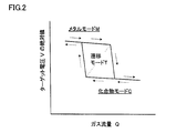
- FIG. 2 and FIG. 3 are diagrams for explaining a film forming mode in the reactive sputtering.
- the flow rate of the inert gas introduced into the vacuum chamber is constant.
- FIG. 2 shows that the target voltage V changes as indicated by the solid line arrow when the gas flow rate Q is gradually increased, and the target voltage V as indicated by the broken line arrow when the gas flow rate Q is gradually reduced. Is shown to change.
- the gas flow rate Q and the target voltage V in reactive sputtering have hysteresis characteristics.
- FIG. 3 shows the relationship between the gas flow rate Q and the target voltage V when the gas flow rate Q is controlled to control the target voltage V to be constant.
- the gas flow rate Q and the target voltage V actually vary, but if their average values are plotted, they are represented as curves as shown in the film formation mode curve D1.
- sputtering is performed under any film forming condition on the film forming mode curve D1.
- the transition mode T on the deposition mode curve D1 exists between the metal mode M and the compound mode C, and a compound thin film is formed on the substrate 50 while keeping the erosion portion of the metal target 113 in the metal state.
- This is a possible mode. Therefore, the transition mode T has the advantages of being capable of forming a film formation rate close to that of the metal mode M and forming a compound thin film having a composition close to that of the compound mode C.
- the transition mode T also has a property that it easily changes to the metal mode M or the compound mode C due to a change in the discharge state in the vacuum chamber. Therefore, in order to maintain the transition mode T during the thin film formation, impedance control for maintaining the target voltage V constant is generally executed.
- Example 9 of Patent Document 1 Japanese Patent Laid-Open No. 2007-63623 discloses knowledge focusing on the relationship between the discharge voltage and the partial pressure of the reaction gas (O 2 gas) in the vacuum chamber. . According to this, the reactive sputtering by the transition mode T can be maintained by setting the discharge voltage and the partial pressure of the reactive gas within a predetermined range (plateau region).
- the inventors have confirmed that the position of the film formation mode curve D1 shifts with time in the direction of arrow SH1 (downward) as shown in FIG. Since the impedance control described above is executed so as to keep the target voltage V constant, based on the film formation mode curve D1 shown in FIG. 4, the film formation conditions shown in the order of points A1, A2, and A3 are used. It will be sputtered. However, if the target voltage V remains constant from beginning to end, the deposition mode curve D1 shifts downward, and the deposition mode shifts from the transition mode T to the metal mode M. Therefore, the film quality of the compound thin film formed on the substrate 50 may differ only by simply executing the impedance control.
- Patent Document 1 discloses the knowledge for sputtering within the range of the transition mode T, but the content of the compound in the compound thin film varies depending on the film formation conditions within the range of the transition mode T. Not taken into account. Further, Patent Document 1 does not specifically show how to set the discharge voltage and the partial pressure of the reaction gas within a predetermined range in the reactive sputtering in which the discharge state is easily changed.
- An object of the present invention is to provide a thin film forming method for forming a compound thin film having a high film forming speed and a stable film quality by solving these problems.
- the thin film forming method according to the present invention includes a first aspect and a second aspect as described below.
- the invention in the first aspect includes a vacuum chamber, a metal target provided in the vacuum chamber, a power source for supplying a constant power to the metal target, and a reaction gas for adjusting a gas flow rate of the reaction gas introduced into the vacuum chamber.
- the gas flow rate monitoring control is executed to change the target voltage of the target voltage at every second cycle time interval so that the gas flow rate value approaches the target gas flow rate value. .
- the value of the gas flow rate is a moving average value of the gas flow rate monitored in the second cycle time.
- the invention in the second aspect includes a vacuum chamber, a metal target disposed in the vacuum chamber, a power source for supplying a constant power to the metal target, and a reaction for adjusting a gas flow rate of a reaction gas introduced into the vacuum chamber.
- current monitoring control is performed to adjust the gas flow rate so that the target current value approaches the target current value by monitoring the target current flowing through the metal target at a predetermined cycle time.
- the value of the gas flow rate is a moving average value of the gas flow rate monitored at another cycle time.
- the voltage is monitored in the first cycle time, the gas flow rate is adjusted so that the target voltage value approaches the target voltage value, and the gas flow rate in the second cycle time is adjusted. Monitoring is performed, and the target voltage of the target voltage is changed so that the value of the gas flow rate approaches the value of the target gas flow rate.
- the current is monitored at a predetermined cycle time, the gas flow rate is adjusted so that the target current value approaches the target current value, and the gas flow rate is monitored at another cycle time.
- the target current of the target current is changed so that the value of the gas flow rate approaches the value of the target gas flow rate.
- FIG. 1 is a front view of a general reactive sputtering apparatus 110.
- FIG. It is a 1st figure for demonstrating the film-forming mode in reactive sputtering. It is a 2nd figure for demonstrating the film-forming mode in reactive sputtering. It is the figure which showed a mode that the position of the film-forming mode curve D1 shown in FIG. 3 shifted below by continuing sputtering.
- 1 is a front view of a reactive sputtering apparatus 10 used in a thin film forming method according to a first embodiment of the present invention. It is a block diagram for demonstrating the thin film formation method which concerns on 1st Embodiment of this invention.
- FIG. 10 is a first diagram showing a change in target voltage Vt in a shorter time than in FIG. 9.
- FIG. 10 is a second diagram showing changes in the gas flow rate Q in a shorter time than in FIG. 9. It is a figure for demonstrating the film-forming mode in reactive sputtering, and is the figure which made the vertical axis
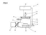
- FIG. 5 is a view showing the reactive sputtering apparatus 10 used in the thin film forming method according to the first embodiment.
- the reactive sputtering apparatus 10 includes a vacuum chamber 11, a metal target 13 provided in the vacuum chamber 11, a power supply 12 that supplies a constant power to the metal target 13, and a flow rate of a reaction gas introduced into the vacuum chamber 11. And a reaction gas introduction valve 15 to be adjusted.
- the inside of the vacuum chamber 11 is evacuated by a vacuum pump 21, an inert gas is introduced via an inert gas introduction valve 16, and a reaction gas is introduced via a reaction gas introduction valve 15.
- the pressure in the vacuum chamber 11 is maintained at a predetermined pressure by an automatic pressure control valve 22 provided between the vacuum chamber 11 and the vacuum pump 21.
- the reaction gas introduction valve 15 has a function of adjusting the gas flow rate and is connected to the control device 18.
- the control device 18 monitors the gas flow rate of the reaction gas and controls the opening and closing of the reaction gas introduction valve 15.
- the metal target 13 is disposed on the target fixing base 14. Examples of the material of the metal target 13 include Si, Al, Ti, and the like.
- the target fixing base 14 incorporates a magnetron (not shown).
- a substrate 50 is disposed so as to face the metal target 13.
- the substrate 50 is disposed on the substrate fixing base 19.
- a shutter 17 is provided between the metal target 13 and the substrate 50 to temporarily prevent the film from adhering to the substrate 50.
- the shutter 17 is opened and closed by a driving mechanism (not shown).
- the metal target 13 is connected to the power supply 12 via the target fixing base 14, and the substrate 50 is connected to, for example, ground via the plate fixing base 19.
- the power source 12 is a constant power source for keeping the power supplied to the metal target 13 constant, and is connected to the control device 18.
- the control device 18 monitors the target voltage V through the power supply 12.
- the power source 12 causes a high potential difference between the metal target 13 and the anode connected to the ground, and the metal target 13 is sputtered.
- the power source 12 may be a direct current power source or a high frequency power source.
- a thin film forming method using this reactive sputtering apparatus 10 will be described.
- a rough flow for forming a thin film on the substrate 50 will be described in order by the following steps S1 to S10.
- S1 The inside of the vacuum chamber 11 is evacuated by the vacuum pump 21, and the pressure in the vacuum chamber 11 is set to a negative pressure. The pressure at this time is, for example, 1.0 ⁇ 10 ⁇ 3 Pa.
- S2 The substrate 50 is placed in the vacuum chamber 11.
- S4 The pressure in the vacuum chamber 11 is set to a predetermined pressure by the automatic pressure control valve 22. The predetermined pressure at this time is, for example, 1.0 Pa.
- S5 The shutter 17 is closed to prevent film adhesion to the substrate 50 during pre-sputtering.
- S6 A voltage is applied to the metal target 13 by turning on the power supply 12, and pre-sputtering is started in the metal mode M. Dirt adhered to the surface of the metal target 13 is removed by pre-sputtering. The reason for starting in the metal mode M is that it is difficult to discharge in the transition mode T suddenly. Note that pre-sputtering may be started in the compound mode C.
- S7 The target voltage V applied to the metal target 13 is changed so that the film formation mode during the thin film formation is the transition mode T, and the transition to the sputtering in the transition mode T is performed.
- step S8 After the time for pre-sputtering has elapsed, the shutter 17 is opened.
- step S9 After step S8, thin film formation on the substrate 50 is started. At this time, the gas flow rate Q shown in step S7 is changed in the short term, and the index (target voltage) of the target voltage V is changed so that the gas flow rate Q is within a predetermined threshold in the long term.
- step S10 After the preset thin film formation time has elapsed, the shutter 17 is closed.
- a thin film is formed on the substrate 50 through the steps S1 to S10 described above.
- steps S1 to S10 the feature of the thin film forming method according to the first embodiment is in step S9.
- FIG. 6 is a block diagram for explaining step S9 in more detail. As shown in FIG. 6, the thin film forming method executed in step S9 includes a voltage monitoring control VC and a gas flow rate monitoring control QC1.
- the voltage monitoring control VC is a control for adjusting the gas flow rate Q so that the value of the target voltage V approaches the value of the target voltage Vt. Since the transition mode T at the time of thin film formation is an unstable discharge state, the target voltage V always varies. Since the gas flow rate Q and the target voltage V have the relationship shown in FIG. 2, the target voltage V can be changed by changing the gas flow rate Q.
- the inputted target voltage Vt is compared with the fed back measurement voltage Vm.
- the target voltage Vt is an index of the target voltage V for performing thin film formation in the transition mode T, and is initially set by collecting data in advance for the target voltage V when the transition mode T is entered.
- the measurement voltage Vm is a measurement value obtained by monitoring the target voltage V when the reactive sputtering apparatus 10 is operated.
- the calculated gas flow rate Qs is calculated according to the difference between the target voltage Vt and the measured voltage Vm.
- the calculated gas flow rate Qs increases the actual gas flow rate Q if the measured voltage Vm is larger than the target voltage Vt, and decreases the actual gas flow rate Q if the measured voltage Vm is smaller than the target voltage Vt. Is calculated.
- PID control Proportional Integral Differential Control
- the reaction gas introduction valve 15 is opened and closed according to the calculated gas flow rate Qs thus calculated, and the gas flow rate Q of the reaction gas introduced into the vacuum chamber 11 is adjusted.
- control is performed so that the value of the target voltage V approaches the value of the target voltage Vt.
- the target voltage V which is the output of the voltage monitoring control VC, is monitored again, and the voltage value is fed back as the measured voltage Vm and compared with the target voltage Vt.
- the target voltage V is maintained within a predetermined range, and the sputtering in the transition mode T is reliably performed.
- the gas flow rate Q and the target voltage V actually vary, but if their average values are taken, they are controlled on the transition mode T of the film forming mode curve D1 shown in FIG.
- the cycle time for executing the voltage monitoring control VC is very short, for example, 0.1 second.
- This voltage monitoring control VC is continuously repeated a plurality of times, and each time the value of the target voltage V is controlled to approach the value of the target voltage Vt.
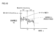
- the cycle time for executing the voltage monitoring control VC is referred to as “first cycle time tv” (see FIGS. 10 and 11).
- the gas flow rate monitoring control QC1 is a control for changing the target voltage Vt of the target voltage V so that the value of the gas flow rate Q approaches the value of the target gas flow rate Qt.
- the value of the target voltage V is controlled to maintain the value of the target voltage Vt by executing the voltage monitoring control VC for each first cycle time tv.
- the film formation mode curve D1 shifts with time in a direction in which the target voltage V decreases, if the target voltage Vt remains constant for a long time, the film formation mode curve D1 changes to the transition mode T of the film formation conditions close to the metal mode M. It will change. Therefore, in order to maintain a predetermined sputtering state in the transition mode T, control is performed to appropriately change the target voltage Vt by monitoring the gas flow rate Q.
- the cycle time for executing the gas flow rate monitoring control QC1 is longer than the first cycle time tv, and is arbitrarily set, for example, between several tens of seconds to several hours.
- the cycle time for executing the gas flow rate monitoring control QC1 is referred to as “second cycle time tq1”.
- the gas flow rate monitoring control QC1 is performed at intervals t1 and t2 of the second cycle time tq1 (see FIGS. 10 and 11).
- the cycle time separation time may be the end of the cycle time, the start of the cycle time, or the time from the end of the cycle time to the start of the next cycle time.
- the input target gas flow rate Qt is compared with the fed back gas flow rate Q value.
- the target gas flow rate Qt is a gas flow rate Q for performing thin film formation in the transition mode T, and is set by taking data in advance for the gas flow rate Q when the transition mode T is entered.
- the target gas flow rate Qt is set to an arbitrary value in order to obtain a desired film quality, but is preferably a fixed value in order to obtain the same film quality.
- the gas flow rate Q to be fed back is specifically the moving average Qma of the gas flow rate monitored at the second cycle time tq1.
- the moving average Qma of the gas flow rate is obtained by averaging the latest gas flow rate Q.
- the time for obtaining the moving average Qma of the gas flow rate is longer than the first cycle time tv, and preferably shorter than the second cycle time tq1.
- the time for obtaining the moving average Qma of the gas flow rate is referred to as “moving average time ta”.
- the moving average Qma of the gas flow rate is obtained by, for example, averaging the gas flow rate Q during the moving average time tab.
- the target voltage Vt is calculated according to the difference between the target gas flow rate Qt and the gas flow rate Q.
- This target voltage Vt is calculated so that the value of the gas flow rate Q approaches the value of the target gas flow rate Qt. Specifically, after using the moving average Qma of the gas flow rate as the gas flow rate Q, the moving average Qma of the gas flow rate is smaller than the current value if the moving average Qma of the gas flow rate is larger than the target gas flow rate Qt. If it is smaller than the target gas flow rate Qt, it is calculated to be larger than the current value. However, since the film formation mode curve D1 shifts downward in the long term, the target voltage Vt is calculated so as to decrease with time. PID control is also employed for calculating the target voltage Vt.
- the input target voltage Vt is input to the voltage monitoring control VC indicated by the broken line to change the initially set target voltage Vt. Based on the changed target voltage Vt, the above-described voltage monitoring control VC is executed. Again, when the gas flow rate Q deviates from the target gas flow rate Qt, the target voltage Vt is corrected by the gas flow rate monitoring control QC1. By repeating these steps, sputtering in the transition mode T is reliably performed, and a thin film is formed in a predetermined sputtering state in the transition mode T.
- FIG. 7 is a diagram conceptually showing changes in the film forming mode in a short time.
- the short time shown here is a time during which the gas flow rate monitoring control QC1 is executed several times, for example, 2 to 20 seconds.
- the film formation mode curve D1 shifts in order from the film formation mode curve Da to the film formation mode curve Db and from the film formation mode curve Db to the film formation mode curve Dc.
- the respective points a1, a2, b1, and b2 on the film formation mode curves Da, Db, and Dc are film formation conditions (target voltage V and gas flow rate Q) for maintaining a predetermined sputtering state in the transition mode T. Is shown.
- the change in the film forming conditions when shifting from the film forming mode curve Da to the film forming mode curve Db is as follows.
- the voltage monitoring control VC is executed on the basis of the film formation condition by the point a1 on the film formation mode curve Da.
- the target voltage va is kept constant by increasing the average value of the gas flow rate Q.
- the film forming condition shifts from the point a1 to the point a2 on the film forming mode curve Db.
- the target voltage va is kept constant as it is, it will deviate greatly from the predetermined sputtering state set at the beginning. Therefore, when the second cycle time tq1 elapses, the gas flow rate monitoring control QC1 is executed with respect to the film forming condition by the point a2. At this time, the target voltage V targeted is lowered from the target voltage va to the target voltage vb. Note that the value of the target voltage vb is determined by PID control. By this control, the film forming condition shifts from point a2 to point b1. Since the position of the point b1 on the film forming mode curve Db is substantially the same as the position of the point a1 on the film forming mode curve Da, the predetermined sputtering state in the transition mode T is maintained.
- the film formation mode curve D changes with time
- the voltage monitoring control VC and the gas flow rate monitoring control QC1 are repeatedly executed, so that the sputtering in the transition mode T is reliably performed and a predetermined value in the transition mode T is obtained. Thin film formation is performed in the sputtering state.
- FIG. 8 is a graph showing the trend of changes in the target voltage Vt and the gas flow rate Q over a long period of time.
- the long time shown here is a time during which the metal target 13 is continuously used, and is, for example, 1 hour or more.
- the trend of change in the moving average of the gas flow rate is constant.
- the tendency of the change in the target voltage Vt decreases to the right with time.
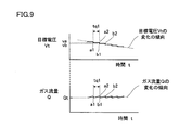
- FIG. 9 is a diagram showing changes in the target voltage Vt and the gas flow rate Q in a short time, and is an enlarged view of the portion E in FIG.
- the short time shown here is a time during which the gas flow rate monitoring control QC1 is executed several times, for example, 2 to 20 seconds. Note that the minute vibration actually measured with respect to the gas flow rate Q is cut off.
- FIG. 9 shows film forming conditions at points a1, a2, b1, and b2 shown in FIG.
- the target voltage va is constant as the voltage monitoring control VC is executed over time from the point a1 to the point a2.
- the gas flow rate monitoring control QC1 is executed, so that the target voltage Vt is changed from the target voltage va to the target voltage vb, and is instantaneously reduced.
- the target voltage vb is constant over time from the point b1 to the point b2. By repeating these steps, the target voltage Vt decreases stepwise.
- the gas flow rate Q gradually increases as the voltage monitoring control VC is executed over time from the point a1 to the point a2.
- the gas flow rate monitoring control QC1 is executed, so that it is instantaneously reduced.
- the gas flow rate Q gradually increases over time from the point b1 to the point b2.
- the gas flow rate Q changes in a sawtooth waveform. Also from FIG. 9, it can be seen that the value of the gas flow rate Q changes at every separation time of the second cycle time tq1 so as to approach the value of the target gas flow rate Qt.
- the voltage V is monitored at the first cycle time tv, the gas flow rate Q is adjusted so that the value of the target voltage V approaches the value of the target voltage Vt, and the gas at the second cycle time tq1.
- the flow rate Q is monitored, and the target voltage Vt of the target voltage V is changed so that the value of the gas flow rate Q approaches the value of the target gas flow rate Qt.
- the value of the gas flow rate Q is preferably the value of the moving average Qma of the gas flow rate monitored at the second cycle time tq1.
- a compound thin film having a stable film quality can be formed at low cost.
- the second embodiment is a thin film formation method in which the target current I is controlled while being monitored instead of the target voltage V shown in the first embodiment.
- the same apparatus as the reactive sputtering apparatus 10 shown in the first embodiment is used.
- the target current I of the power supply 12 is monitored, since the target current cannot be monitored with the RF power supply, the control with the target current is only for the DC power supply.
- the description of the configuration common to the first embodiment is omitted.
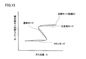
- the film formation mode curve D2 is a curve shown in FIG. 13, and the metal mode (M), the compound mode (C), and the transition mode (T) are arranged as shown in FIG.
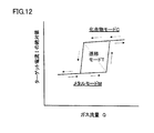
- FIG. 12 shows that the target current I changes as indicated by the solid line arrow when the gas flow rate Q is gradually increased, and the target current I as indicated by the broken line arrow when the gas flow rate Q is gradually reduced. Is shown to change.
- the gas flow rate Q and the target current I in reactive sputtering have hysteresis characteristics.
- FIG. 13 shows the relationship between the gas flow rate Q and the target current I when the gas flow rate Q is controlled in order to control the target current I at a constant level.
- the gas flow rate Q and the target current I actually vary, but if each average value is plotted, the gas flow rate Q and the target current I are represented as curves as shown in the film formation mode curve D2.
- sputtering is performed under any film forming condition on the film forming mode curve D2.
- the position of the film forming mode curve D2 shifts with time in the direction of arrow SH2 (upward).
- sputtering is controlled so as to correspond to the change with time of the film formation mode curve D2.
- the thin film forming method according to the second embodiment includes a current monitoring control IC and a gas flow rate monitoring control QC2, as shown in the block diagram of FIG.
- the current monitoring control IC is a control for adjusting the gas flow rate Q so that the value of the target current I approaches the value of the target current It.
- the inputted target current It is compared with the fed back measured current Im.
- the target current It is a target current I for forming a thin film in the transition mode T, and is initially set by collecting data in advance for the target current I when the transition mode T is entered.
- the measurement current Im is a measurement value obtained by monitoring the target current I when the reactive sputtering apparatus 10 is operated.
- the calculated gas flow rate Qs is calculated according to the difference between the target current It and the measured current Im. As shown in FIG. 12, when the gas flow rate Q is increased, the absolute value of the target current I increases, and when the gas flow rate Q is decreased, the absolute value of the target current I decreases.
- the calculated gas flow rate Qs is calculated so as to decrease the actual gas flow rate Q if the measured current Im is larger than the target current It, and to increase the actual gas flow rate Q if the measured current Im is smaller than the target current It. Is done.
- PID control is employed for calculating the gas flow rate Qs.
- the reaction gas introduction valve 15 is opened and closed according to the calculated gas flow rate Qs thus calculated, and the gas flow rate Q of the reaction gas introduced into the vacuum chamber 11 is adjusted.
- the target current I is controlled to maintain the target current It.
- the target current I that is the output of the current monitoring control IC is monitored again, and the current value is fed back as the measured current Im and compared with the target current It.
- the target current I is maintained within a predetermined range, and the sputtering in the transition mode T is reliably performed.
- the gas flow rate Q and the target current I actually vary, but if their average values are taken, they are controlled on the transition mode T of the film forming mode curve D2 shown in FIG.
- the cycle time for executing the current monitoring control IC is very short, for example, 0.1 seconds.
- This current monitoring control IC is continuously repeated a plurality of times, and each time the target current I is controlled to maintain the target current It.
- the cycle time for executing the current monitoring control IC is referred to as “predetermined cycle time ti”.
- the gas flow rate monitoring control QC2 is a control for changing the target current It of the target current I so that the value of the gas flow rate Q approaches the value of the target gas flow rate Qt.
- the cycle time for executing the gas flow rate monitoring control QC2 is longer than a predetermined cycle time ti, and is arbitrarily set, for example, between several tens of seconds to several hours.
- the cycle time for executing the gas flow rate monitoring control QC2 is referred to as “another cycle time tq2.”
- the gas flow rate monitoring control QC2 is performed at every interval time of another cycle time tq2.
- the input target gas flow rate Qt is compared with the fed back gas flow rate Q value.
- the target gas flow rate Qt is a gas flow rate Q for performing thin film formation in the transition mode T, and is set by taking data in advance for the gas flow rate Q when the transition mode T is entered.
- the gas flow rate Q to be fed back is specifically a moving average Qma of the gas flow rate monitored at another cycle time tq2.
- the moving average Qma of the gas flow rate is obtained by averaging the latest gas flow rate Q.
- the time for acquiring the moving average Qma of the gas flow rate is a time longer than the predetermined cycle time ti and shorter than another cycle time tq2.
- the time for obtaining the moving average Qma of the gas flow rate is referred to as “moving average time ta”.
- the target current It is calculated according to the difference between the target gas flow rate Qt and the gas flow rate Q.
- This target current It is calculated so that the value of the gas flow rate Q approaches the value of the target gas flow rate Qt. Specifically, after using the moving average Qma of the gas flow rate as the gas flow rate Q, the moving average Qma of the gas flow rate is larger than the current value if the moving average Qma of the gas flow rate is larger than the target gas flow rate Qt. If it is smaller than the target gas flow rate Qt, it is calculated to be smaller than the current value. However, since the film forming mode curve D2 shifts upward in the long term, the target current It is calculated so as to increase with time. PID control is also employed for calculating the target current It.
- the input target current It is input to the current monitoring control IC indicated by the broken line to change the initially set target current It. Based on the changed target current It, the above-described current monitoring control IC is executed. Again, when the gas flow rate Q deviates from the target gas flow rate Qt, the target current It is corrected by the gas flow rate monitoring control QC2. By repeating these steps, the gas flow rate monitoring control QC2 is executed.
- the current I is monitored at a predetermined cycle time ti
- the gas flow rate Q is adjusted so that the value of the target current I approaches the value of the target current It, and the gas flow rate Q at another cycle time tq2.
- the target current It of the target current I is changed so that the value of the gas flow rate Q approaches the value of the target gas flow rate Qt.
- the value of the gas flow rate Q is preferably the value of the moving average Qma of the gas flow rate monitored at another cycle time tq2.
- a compound thin film having a stable film quality can be formed at low cost without using an expensive plasma emission monitor device.
- the voltage monitoring control and the current monitoring control may be executed by changing the proportion of the reactive gas by changing the flow rate of the inert gas.
- the gas flow rate monitoring control may be executed by setting the ratio of the moving average of the inert gas flow rate to the moving average of the reactive gas flow rate within a predetermined range.
Landscapes
- Chemical & Material Sciences (AREA)
- Engineering & Computer Science (AREA)
- Organic Chemistry (AREA)
- Materials Engineering (AREA)
- Mechanical Engineering (AREA)
- Metallurgy (AREA)
- Chemical Kinetics & Catalysis (AREA)
- Physics & Mathematics (AREA)
- Fluid Mechanics (AREA)
- Health & Medical Sciences (AREA)
- Toxicology (AREA)
- Plasma & Fusion (AREA)
- Analytical Chemistry (AREA)
- Physical Vapour Deposition (AREA)
Abstract
反応性スパッタリングにおいて、成膜速度が速く、膜質の安定した化合物薄膜を得る。電圧モニタリング制御(VC)、および、ガス流量モニタリング制御(QC1)により薄膜を形成する。電圧モニタリング制御(VC)は、第1のサイクルタイム(tv)において、ターゲット電圧(V)をモニタリングすることにより、ターゲット電圧(V)の値を目標電圧(Vt)の値に近づけるようにガス流量(Q)を調整する制御である。ガス流量モニタリング制御(QC1)は、第2のサイクルタイム(tq1(>tv))において、ガス流量(Q)をモニタリングすることにより、ガス流量(Q)の値を目標ガス流量(Qt)の値に近づけるようにターゲット電圧(V)の目標電圧(Vt)を変更する制御である。
Description
本発明は、反応性スパッタ装置を用いて基板に薄膜を形成する薄膜形成方法であって、特に、薄膜形成時における反応性スパッタリングを遷移モード(遷移領域)で行なう薄膜形成方法に関する。
基板上に酸化物や窒化物などの化合物薄膜を形成する装置として、図1に示すような反応性スパッタ装置110が知られている。反応性スパッタ装置110は、真空チャンバ111と、真空チャンバ111内に設けられる金属ターゲット113と、金属ターゲット113に一定電力を供給する電源112と、を備える。真空チャンバ111内には、金属ターゲット113と対向する位置に基板50が配置される。真空チャンバ111内は、真空ポンプ121により真空引きされるとともに、不活性ガス導入弁116を介して不活性ガスが導入され、反応ガス導入弁115を介して反応ガスが導入される。真空チャンバ111内の圧力は、真空チャンバ111と真空ポンプ121の間に設けられた自動圧力調整弁122により所定の圧力に保たれる。
図2および図3は、反応性スパッタリングにおける成膜モードを説明するための図であり、金属ターゲットに印加されるターゲット電圧Vの絶対値と、真空チャンバ内に導入される反応ガスのガス流量Qとの関係が示されている。真空チャンバ内に導入される不活性ガスの流量は一定とする。反応性スパッタリングにおける成膜モードには、メタルモードM、化合物モードCおよび遷移モードTがある。
図2には、ガス流量Qを徐々に増やした場合に実線矢印で示すようにターゲット電圧Vが変化すること、また、ガス流量Qを徐々に減らした場合に破線矢印で示すようにターゲット電圧Vが変化すること、が示されている。このように、反応性スパッタリングにおけるガス流量Qおよびターゲット電圧Vは、ヒステリシス特性を有する。
図3には、ターゲット電圧Vを一定に制御するためにガス流量Qを制御した場合のガス流量Qおよびターゲット電圧Vの関係が示されている。ガス流量Qおよびターゲット電圧Vは、実際にはばらつきを有するが、それぞれの平均値をプロットすれば、成膜モード曲線D1に示すような曲線として表される。薄膜形成時は、この成膜モード曲線D1上にあるいずれかの成膜条件でスパッタリングされる。
成膜モード曲線D1上にある遷移モードTは、メタルモードMと化合物モードCの間に存在し、金属ターゲット113の浸食(エロージョン)部分をメタル状態に保ちつつ、基板50上に化合物薄膜を形成できるモードである。そのため、遷移モードTは、メタルモードMに近い成膜速度が得られ、化合物モードCに近い組成の化合物薄膜を形成できるという両方の長所を持つ。ただし、遷移モードTは、真空チャンバ内の放電状態の変化により、メタルモードMまたは化合物モードCへ変化しやすいという性質もある。そこで、薄膜形成時において遷移モードTを維持するため、ターゲット電圧Vを一定に維持するインピーダンス制御が一般的に実行される。
また、特許文献1(特開2007-63623号公報)の実施例9には、放電電圧と、真空チャンバ内における反応ガス(O2ガス)の分圧との関係に着目した知見が開示されている。これによれば、放電電圧および反応ガスの分圧を所定範囲(プラトー領域)とすることにより、遷移モードTによる反応性スパッタリングを維持することができる。
定電力制御により長時間にわたりスパッタリングを行なうと、金属ターゲットの浸食によって、ターゲット電圧Vの絶対値が小さくなることが知られている。それに関して発明者らは、図4に示すように、成膜モード曲線D1の位置が矢印SH1の方向(下方)へ経時的にシフトすることを確認している。先述したインピーダンス制御はターゲット電圧Vを一定に維持するように実行されるので、図4に示した成膜モード曲線D1に基づけば、点A1、A2、A3の順で示すような成膜条件でスパッタリングされることになる。しかし、ターゲット電圧Vが終始一定のままだと、成膜モード曲線D1が下方へシフトすることにより、成膜モードが遷移モードTからメタルモードMへ移行してしまう。そのため、単純にインピーダンス制御を実行しただけでは、基板50に形成される化合物薄膜の膜質が異なってしまうこともある。
また、同じ遷移モードTでスパッタリングしたとしても、メタルモードMに近い成膜条件と、化合物モードCに近い成膜条件と、遷移モードTの中央における成膜条件とでは、薄膜形成後における化合物薄膜中の化合物の含有率が微妙に異なる。それに対し、特許文献1には、遷移モードTの範囲内でスパッタリングするための知見は示されているが、遷移モードTの範囲内の成膜条件によって化合物薄膜中の化合物の含有率が異なることまで考慮されていない。なおかつ、特許文献1には、放電状態の変化しやすい反応性スパッタリングにおいて、放電電圧および反応ガスの分圧をどのようにして所定範囲とするかについて具体的に示されていない。
本発明の目的は、これらの課題を解決することにより、成膜速度が速く、膜質が安定した化合物薄膜を形成するための薄膜形成方法を提供することである。
本発明に係る薄膜形成方法には、以下に示すように、第1の局面と第2の局面とがある。
第1の局面における発明は、真空チャンバと、真空チャンバ内に設けられる金属ターゲットと、金属ターゲットに一定電力を供給する電源と、真空チャンバ内に導入される反応ガスのガス流量を調整する反応ガス導入弁と、を備える反応性スパッタ装置を用いて、真空チャンバ内に配置される基板に薄膜を形成する薄膜形成方法であって、薄膜形成中におけるスパッタリングを、メタルモードと化合物モードの間に存在する遷移モードで行なうため、第1のサイクルタイムにおいて、金属ターゲットに印加されるターゲット電圧をモニタリングすることにより、ターゲット電圧の値を目標電圧の値に近づけるようにガス流量を調整する電圧モニタリング制御を実行するとともに、第1のサイクルタイムよりも長い第2のサイクルタイムにおいて、ガス流量をモニタリングすることにより、ガス流量の値を目標ガス流量の値に近づけるように、第2のサイクルタイムの区切り時間ごとにターゲット電圧の目標電圧を変更するガス流量モニタリング制御を実行する。
好ましくは、ガス流量の値は、第2のサイクルタイムにおいてモニタリングされたガス流量の移動平均値である。
第2の局面における発明は、真空チャンバと、真空チャンバ内に配置される金属ターゲットと、金属ターゲットに一定電力を供給する電源と、真空チャンバ内に導入される反応ガスのガス流量を調整する反応ガス導入弁と、を備える反応性スパッタ装置を用いて、真空チャンバ内に配置された基板に薄膜を形成する薄膜形成方法であって、薄膜形成中におけるスパッタリングを、メタルモードと化合物モードの間に存在する遷移モードで行なうため、所定のサイクルタイムにおいて、金属ターゲットに流れるターゲット電流をモニタリングすることにより、ターゲット電流の値を目標電流の値に近づけるようにガス流量を調整する電流モニタリング制御を実行するとともに、所定のサイクルタイムよりも長い別のサイクルタイムにおいて、ガス流量をモニタリングすることにより、ガス流量の値を目標ガス流量の値に近づけるように、別のサイクルタイムの区切り時間ごとにターゲット電流の目標電流を変更するガス流量モニタリング制御を実行する。
好ましくは、ガス流量の値は、別のサイクルタイムにおいてモニタリングされたガス流量の移動平均値である。
第1の局面における発明によれば、第1のサイクルタイムにおいて電圧をモニタリングして、ターゲット電圧の値を目標電圧の値に近づけるようにガス流量を調整し、第2のサイクルタイムにおいてガス流量をモニタリングして、ガス流量の値を目標ガス流量の値に近づけるようにターゲット電圧の目標電圧を変更する。これにより、遷移モードでのスパッタリングを確実に行なうことができ、かつ、遷移モード内の所定のスパッタリング状態を維持することができる。その結果、成膜速度が速く、膜質が安定した化合物薄膜を形成できる。
第2の局面における発明によれば、所定のサイクルタイムにおいて電流をモニタリングして、ターゲット電流の値を目標電流の値に近づけるようにガス流量を調整し、別のサイクルタイムにおいてガス流量をモニタリングして、ガス流量の値を目標ガス流量の値に近づけるようにターゲット電流の目標電流を変更する。これにより、遷移モードでのスパッタリングを確実に行なうことができ、かつ、遷移モード内の所定のスパッタリング状態を維持することができる。その結果、成膜速度が速く、膜質が安定した化合物薄膜を形成できる。
[第1実施形態]
図5は、第1実施形態に係る薄膜形成方法にて用いられる反応性スパッタ装置10を示した図である。反応性スパッタ装置10は、真空チャンバ11と、真空チャンバ11内に設けられる金属ターゲット13と、金属ターゲット13に一定電力を供給する電源12と、真空チャンバ11内に導入される反応ガスの流量を調整する反応ガス導入弁15と、を有する。真空チャンバ11内は、真空ポンプ21により真空引きされるとともに、不活性ガス導入弁16を介して不活性ガスが導入され、反応ガス導入弁15を介して反応ガスが導入される。真空チャンバ11内の圧力は、真空チャンバ11と真空ポンプ21の間に設けられた自動圧力調整弁22により所定の圧力に保たれる。
図5は、第1実施形態に係る薄膜形成方法にて用いられる反応性スパッタ装置10を示した図である。反応性スパッタ装置10は、真空チャンバ11と、真空チャンバ11内に設けられる金属ターゲット13と、金属ターゲット13に一定電力を供給する電源12と、真空チャンバ11内に導入される反応ガスの流量を調整する反応ガス導入弁15と、を有する。真空チャンバ11内は、真空ポンプ21により真空引きされるとともに、不活性ガス導入弁16を介して不活性ガスが導入され、反応ガス導入弁15を介して反応ガスが導入される。真空チャンバ11内の圧力は、真空チャンバ11と真空ポンプ21の間に設けられた自動圧力調整弁22により所定の圧力に保たれる。
不活性ガスとしては、たとえばArガスが用いられ、反応ガスとしては、たとえばO2ガス、N2ガスなどが用いられる。反応ガス導入弁15はガス流量を調整する機能を有し、制御装置18に接続される。制御装置18は、反応ガスのガス流量をモニタリングするとともに、反応ガス導入弁15の開閉を制御する。金属ターゲット13は、ターゲット固定台14に配置される。金属ターゲット13の材質としては、たとえばSi、Al、Tiなどが挙げられる。ターゲット固定台14には図示しないマグネトロンが内蔵される。
真空チャンバ11内には、金属ターゲット13と対向するように基板50が配置される。基板50は、基板固定台19に配置される。金属ターゲット13と基板50との間には、基板50への膜付着を一時的に防止するためのシャッタ17が設けられる。シャッタ17は図示しない駆動機構により開閉される。
金属ターゲット13はターゲット固定台14を介して電源12に接続され、基板50は、板固定台19を介して、たとえばアースに接続される。電源12は、金属ターゲット13に供給される電力を一定とするための定電力電源であり、制御装置18に接続される。制御装置18は、電源12を通じてターゲット電圧Vをモニタリングする。この電源12により、金属ターゲット13と、アースに接続されているアノードとの間に高い電位差が生じて、金属ターゲット13がスパッタリングされる。電源12は直流電源であってもよいし、高周波電源であってもよい。
この反応性スパッタ装置10を用いた薄膜形成方法について説明する。まず、基板50に薄膜を形成するための大まかな流れを、次に示すステップS1~S10により順に説明する。
S1:真空チャンバ11内を真空ポンプ21により真空引きし、真空チャンバ11内の圧力を負圧にする。このときの圧力は、たとえば1.0×10⁻³Paである。
S2:基板50を真空チャンバ11内に配置する。
S3:真空チャンバ11内に、不活性ガスとしてArガスを、反応ガスとしてO2ガスを導入する。
S4:自動圧力調整弁22により真空チャンバ11内の圧力を所定圧力とする。このときの所定圧力は、たとえば1.0Paである。
S5:プリスパッタ(Pre-Sputter)する際に、基板50への膜付着を防止するため、シャッタ17を閉じる。
S6:電源12をONすることにより金属ターゲット13に電圧を印加し、メタルモードMにてプリスパッタを開始する。プリスパッタにより、金属ターゲット13の表面に付着している汚れなどを除去する。メタルモードMで開始する理由は、いきなり遷移モードTにて放電することが困難なためである。なお、化合物モードCにてプリスパッタを開始してもよい。
S7:薄膜形成時の成膜モードが遷移モードTとなるように、金属ターゲット13に印加されるターゲット電圧Vを変更し、遷移モードTでのスパッタリングに移行させる。このとき、インピーダンス制御を行ない、ターゲット電圧Vが目標範囲に収まるように反応ガスのガス流量Qを調整する。なお、不活性ガスの流量は一定である。
S8:プリスパッタのための時間が経過した後、シャッタ17を開ける。
S9:ステップS8の後、基板50への薄膜形成を開始する。このとき、ステップS7で示したガス流量Qを短期的に変化させるとともに、長期的にはガス流量Qが所定閾値内に収まるようにターゲット電圧Vの指標(目標電圧)を変える。
S10:予め設定された薄膜形成時間が経過した後、シャッタ17を閉じる。
S1:真空チャンバ11内を真空ポンプ21により真空引きし、真空チャンバ11内の圧力を負圧にする。このときの圧力は、たとえば1.0×10⁻³Paである。
S2:基板50を真空チャンバ11内に配置する。
S3:真空チャンバ11内に、不活性ガスとしてArガスを、反応ガスとしてO2ガスを導入する。
S4:自動圧力調整弁22により真空チャンバ11内の圧力を所定圧力とする。このときの所定圧力は、たとえば1.0Paである。
S5:プリスパッタ(Pre-Sputter)する際に、基板50への膜付着を防止するため、シャッタ17を閉じる。
S6:電源12をONすることにより金属ターゲット13に電圧を印加し、メタルモードMにてプリスパッタを開始する。プリスパッタにより、金属ターゲット13の表面に付着している汚れなどを除去する。メタルモードMで開始する理由は、いきなり遷移モードTにて放電することが困難なためである。なお、化合物モードCにてプリスパッタを開始してもよい。
S7:薄膜形成時の成膜モードが遷移モードTとなるように、金属ターゲット13に印加されるターゲット電圧Vを変更し、遷移モードTでのスパッタリングに移行させる。このとき、インピーダンス制御を行ない、ターゲット電圧Vが目標範囲に収まるように反応ガスのガス流量Qを調整する。なお、不活性ガスの流量は一定である。
S8:プリスパッタのための時間が経過した後、シャッタ17を開ける。
S9:ステップS8の後、基板50への薄膜形成を開始する。このとき、ステップS7で示したガス流量Qを短期的に変化させるとともに、長期的にはガス流量Qが所定閾値内に収まるようにターゲット電圧Vの指標(目標電圧)を変える。
S10:予め設定された薄膜形成時間が経過した後、シャッタ17を閉じる。
以上に示したステップS1~S10により、基板50に薄膜が形成される。ステップS1~S10の中で、第1実施形態に係る薄膜形成方法の特徴は、ステップS9にある。
図6は、このステップS9をさらに詳しく説明するためのブロック線図である。ステップS9において実行される薄膜形成方法は、図6に示すとおり、電圧モニタリング制御VCと、ガス流量モニタリング制御QC1と、により構成される。
電圧モニタリング制御VCは、ターゲット電圧Vの値を目標電圧Vtの値に近づけるようにガス流量Qを調整する制御である。薄膜形成時の遷移モードTは不安定な放電状態であるため、ターゲット電圧Vは常時変動する。ガス流量Qおよびターゲット電圧Vは、図2に示したような関係があるので、ガス流量Qを変化させることにより、ターゲット電圧Vを変化させることができる。
電圧モニタリング制御VCでは、まず、入力された目標電圧Vtと、フィードバックされた測定電圧Vmと、を比較する。目標電圧Vtは、薄膜形成を遷移モードTで行なうためのターゲット電圧Vの指標であり、遷移モードTとなるときのターゲット電圧Vを事前にデータ取りすることにより初期設定される。測定電圧Vmは、反応性スパッタ装置10を稼働させたときのターゲット電圧Vをモニタリングすることにより得られる測定値である。
次に、目標電圧Vtと測定電圧Vmとの差に応じて、計算上のガス流量Qsを算出する。図2に示すようにガス流量Qを増加させると、ターゲット電圧Vの絶対値は小さくなり、ガス流量Qを減少させると、ターゲット電圧Vの絶対値は大きくなる。よって、計算上のガス流量Qsは、測定電圧Vmが目標電圧Vtより大きければ実際のガス流量Qを増加させるように、測定電圧Vmが目標電圧Vtより小さければ実際のガス流量Qを減少させるように算出される。このガス流量Qsの算出には、たとえば、PID制御(Proportional Integral Differential Control)が採用される。
求めた計算上のガス流量Qsにしたがって反応ガス導入弁15の開閉を行ない、真空チャンバ11内に導入される反応ガスのガス流量Qを調整する。ガス流量Qを調整することにより、ターゲット電圧Vの値を目標電圧Vtの値に近づけるように制御する。そして再び、電圧モニタリング制御VCの出力であるターゲット電圧Vをモニタリングし、その電圧値を測定電圧Vmとしてフィードバックして目標電圧Vtと比較する。これらの繰り返しにより、ターゲット電圧Vが所定範囲に維持され、遷移モードTによるスパッタリングが確実に行なわれる。なお、ガス流量Qおよびターゲット電圧Vは、実際にはばらつきを有するが、それぞれの平均値をとれば、図3に示す成膜モード曲線D1の遷移モードT上で制御される。
電圧モニタリング制御VCを実行するサイクルタイムは、非常に短時間であり、たとえば0.1秒である。この電圧モニタリング制御VCが連続的に複数回繰り返され、その都度、ターゲット電圧Vの値は目標電圧Vtの値に近づくように制御される。以下、電圧モニタリング制御VCを実行するサイクルタイムを「第1のサイクルタイムtv」と呼ぶ(図10および図11参照)。
ガス流量モニタリング制御QC1は、ガス流量Qの値を目標ガス流量Qtの値に近づけるように、ターゲット電圧Vの目標電圧Vtを変更する制御である。前述したとおり、第1のサイクルタイムtvごとに電圧モニタリング制御VCが実行されることにより、ターゲット電圧Vの値は目標電圧Vtの値を維持するように制御される。しかし、成膜モード曲線D1は、ターゲット電圧Vが小さくなる方向に経時的にシフトするので、目標電圧Vtが長時間にわたり一定のままだと、メタルモードMに近い成膜条件の遷移モードTに変わってしまう。そこで、遷移モードT内の所定のスパッタリング状態を維持するために、ガス流量Qをモニタリングすることにより目標電圧Vtを適切に変更する制御を行なう。
ガス流量モニタリング制御QC1を実行するサイクルタイムは第1のサイクルタイムtvよりも長く、たとえば、数十秒~数時間の間で任意に設定される。以下、ガス流量モニタリング制御QC1を実行するサイクルタイムを「第2のサイクルタイムtq1」と呼ぶ。ガス流量モニタリング制御QC1は、第2のサイクルタイムtq1の区切り時間t1、t2ごとに行なわれる(図10および図11参照)。なお、サイクルタイムの区切り時間は、サイクルタイム終了時であってもよいし、サイクルタイム開始時であってもよいし、サイクルタイム終了から次のサイクルタイム開始までの時間であってもよい。
ガス流量モニタリング制御QC1では、まず、入力された目標ガス流量Qtの値とフィードバックされたガス流量Qの値とを比較する。
目標ガス流量Qtは、薄膜形成を遷移モードTで行なうためのガス流量Qであり、遷移モードTとなるときのガス流量Qを事前にデータ取りすることにより設定される。この目標ガス流量Qtは、所望の膜質を得るために任意の値に設定されるが、同一の膜質を得る場合には固定値とするのが望ましい。
フィードバックされるガス流量Qは、具体的には、第2のサイクルタイムtq1においてモニタリングされたガス流量の移動平均Qmaである。ガス流量の移動平均Qmaは、直近のガス流量Qを平均することにより取得される。ガス流量の移動平均Qmaを取得するための時間は、第1のサイクルタイムtvよりも長く、好ましくは第2のサイクルタイムtq1よりも短い時間である。以下、ガス流量の移動平均Qmaを取得するための時間を「移動平均時間ta」と呼ぶ。
図10および図11には、第1のサイクルタイムtv、第2のサイクルタイムtq1および移動平均時間(ta)が示されている。また、移動平均時間(ta)として、具体的に移動平均時間taa、tab、tacが示されている。ガス流量の移動平均Qmaは、たとえば、移動平均時間tabのガス流量Qを平均することにより取得される。このように、ガス流量Qまたはガス流量の移動平均Qmaを定期的にフィードバックすることにより、金属ターゲット13の浸食状態にあわせた薄膜形成が可能となり、所定のスパッタリング状態を維持することができる。
次に、目標ガス流量Qtとガス流量Qとの差に応じて、目標電圧Vtを算出する。この目標電圧Vtは、ガス流量Qの値を目標ガス流量Qtの値に近づけるように算出される。具体的には、ガス流量Qとしてガス流量の移動平均Qmaを用いた上で、ガス流量の移動平均Qmaが目標ガス流量Qtより大きければ現在値より小さくなるように、ガス流量の移動平均Qmaが目標ガス流量Qtより小さければ現在値より大きくなるように算出される。ただし長期的に見れば、成膜モード曲線D1は下方へシフトするので、目標電圧Vtは時間経過とともに小さくなるように算出される。この目標電圧Vtの算出にもPID制御が採用される。
求めた目標電圧Vtを、破線で示された電圧モニタリング制御VCに対して入力することにより、初期設定された目標電圧Vtの値を変更する。この変更した目標電圧Vtに基づいて、先述した電圧モニタリング制御VCが実行される。そして再び、ガス流量Qが目標ガス流量Qtからずれたときに、ガス流量モニタリング制御QC1により目標電圧Vtが補正される。これらの繰り返しにより、遷移モードTによるスパッタリングが確実に行なわれ、かつ、遷移モードT内の所定のスパッタリング状態にて薄膜形成が行なわれる。
ここで、図7を参照しながら、電圧モニタリング制御VCおよびガス流量モニタリング制御QC1が実行されているときの成膜モードの変化について説明する。図7は、短時間における成膜モードの変化を概念的に示した図である。ここで示す短時間とは、ガス流量モニタリング制御QC1が数回実行される時間であり、たとえば2秒~20秒である。この時間において、成膜モード曲線D1は、成膜モード曲線Daから成膜モード曲線Dbへ、成膜モード曲線Dbから成膜モード曲線Dcへ、順にシフトする。成膜モード曲線Da、Db、Dc上にあるそれぞれの点a1、a2、b1、b2は、遷移モードT内の所定のスパッタリング状態を維持するための成膜条件(ターゲット電圧Vおよびガス流量Q)を示している。
成膜モード曲線Daから成膜モード曲線Dbへシフトする際の成膜条件の変化は、以下に示すとおりである。はじめに、成膜モード曲線Da上の点a1による成膜条件をベースにして電圧モニタリング制御VCが実行される。電圧モニタリング制御VCでは、ガス流量Qの平均値を増加させることによりターゲット電圧vaが一定に維持される。この制御により、成膜条件は、点a1から成膜モード曲線Db上の点a2へ移行する。
仮に、ターゲット電圧vaをこのまま一定に保ち続けると、はじめに設定した所定のスパッタリング状態から大きくずれてしまう。そこで、第2のサイクルタイムtq1が経過した際に、点a2による成膜条件に対してガス流量モニタリング制御QC1が実行される。このとき、目標とするターゲット電圧Vがターゲット電圧vaからターゲット電圧vbに引き下げられる。なお、ターゲット電圧vbの値は、PID制御により決定される。この制御により、成膜条件は点a2から点b1へ移行する。成膜モード曲線Db上の点b1の位置は、成膜モード曲線Da上の点a1の位置とほぼ同じであるので、遷移モードT内の所定のスパッタリング状態が維持される。
成膜モード曲線Dbから成膜モード曲線Dcへシフトする際の成膜条件の変化も同様であり、成膜条件は点b1をベースに電圧モニタリング制御VCが実行され、点b2へ移行する。成膜モード曲線Dは経時的に変化するが、電圧モニタリング制御VCおよびガス流量モニタリング制御QC1が繰り返し実行されることにより、遷移モードTによるスパッタリングが確実に行なわれ、かつ、遷移モードT内の所定のスパッタリング状態にて薄膜形成が行なわれる。
さらに理解を深めるため、目標電圧Vtおよびガス流量Qの変化について、長期的または短期的な視点で説明する。
図8は、長時間における目標電圧Vtおよびガス流量Qの変化の傾向を示した図である。ここで示す長時間とは、金属ターゲット13が継続して使用される時間であり、たとえば1時間以上である。長時間で見ると、ガス流量の移動平均の変化の傾向は一定である。目標電圧Vtの変化の傾向は時間経過とともに右下がりとなる。
図9は、短時間における目標電圧Vtおよびガス流量Qの変化を示した図であり、図8におけるE部を拡大した図である。ここで示す短時間とは、ガス流量モニタリング制御QC1が数回実行される時間であり、たとえば2秒~20秒である。なお、ガス流量Qに関して実測される微動な振れはカットオフしている。また、図9には、図7に示した点a1、a2、b1、b2の成膜条件を記している。
図9では、目標電圧vaは、点a1から点a2への時間経過において、電圧モニタリング制御VCが実行されることにより、一定となっている。点a2から点b1への移行に際しては、ガス流量モニタリング制御QC1が実行されることにより、目標電圧Vtが目標電圧vaから目標電圧vbに変更されて、瞬間的に小さくなっている。そして、点b1から点b2への時間経過において、目標電圧vbは一定となっている。これらの繰り返しにより目標電圧Vtは、階段状に小さくなっている。
ガス流量Qは、点a1から点a2への時間経過において、電圧モニタリング制御VCが実行されることにより、徐々に大きくなっている。点a2から点b1への移行に際しては、ガス流量モニタリング制御QC1が実行されることにより、瞬間的に小さくなっている。そして、点b1から点b2への時間経過において、ガス流量Qは徐々に大きくなっている。これらの繰り返しによりガス流量Qは、のこぎり波状に変化している。図9からも、ガス流量Qの値が目標ガス流量Qtの値に近づくように、第2のサイクルタイムtq1の区切り時間ごとに変化していることがわかる。
このように短期的に見ると、ターゲット電圧Vを一定に維持するスパッタリングが繰り返し行なわれており、長期的に見ると、目標電圧Vtを右下がりで小さくすることにより、成膜モード曲線D1の変化を考慮したスパッタリングが行なわれている。
第1実施形態では、第1のサイクルタイムtvにおいて電圧Vをモニタリングして、ターゲット電圧Vの値を目標電圧Vtの値に近づけるようにガス流量Qを調整し、第2のサイクルタイムtq1においてガス流量Qをモニタリングして、ガス流量Qの値を目標ガス流量Qtの値に近づけるようにターゲット電圧Vの目標電圧Vtを変更する。これにより、遷移モードTでのスパッタリングを確実に行なうとともに、遷移モードT内の所定のスパッタリング状態を維持することができる。その結果、成膜速度が速く、膜質の安定した化合物薄膜を形成できる。
ガス流量Qの値は、第2のサイクルタイムtq1においてモニタリングされたガス流量の移動平均Qmaの値とすることが好ましい。ガス流量の移動平均Qmaを用いることにより、ガス流量の突発的な測定値に左右されることなく、安定した目標電圧Vtの値を得ることができる。
また、第1実施形態では高価なプラズマ発光モニタ機器を使用していないので、膜質の安定した化合物薄膜を安価に形成できる。
[第2実施形態]
第2実施形態は、第1実施形態で示したターゲット電圧Vに替えてターゲット電流Iをモニタリングしながら制御する薄膜形成方法である。基板50へ薄膜形成する際は、第1実施形態で示した反応性スパッタ装置10と同じ装置を用いる。モニタリングするのは電源12のターゲット電流Iであるが、RF電源ではターゲット電流をモニタリングすることができないため、ターゲット電流による制御はDC電源の場合のみとなる。第1実施形態と共通する構成については、説明を省略する。
第2実施形態は、第1実施形態で示したターゲット電圧Vに替えてターゲット電流Iをモニタリングしながら制御する薄膜形成方法である。基板50へ薄膜形成する際は、第1実施形態で示した反応性スパッタ装置10と同じ装置を用いる。モニタリングするのは電源12のターゲット電流Iであるが、RF電源ではターゲット電流をモニタリングすることができないため、ターゲット電流による制御はDC電源の場合のみとなる。第1実施形態と共通する構成については、説明を省略する。
図12および図13は、反応性スパッタリングにおける成膜モードを説明するための図であり、金属ターゲット13に流れるターゲット電流Iの絶対値と、真空チャンバ11内に導入される反応ガスのガス流量Qとの関係が示されている。定電力制御の場合、ターゲット電流Iはターゲット電圧Vの逆数で表される。したがって、成膜モード曲線D2は図13に示す曲線となり、メタルモード(M)、化合物モード(C)、遷移モード(T)は図13に示す配置となる。
図12には、ガス流量Qを徐々に増やした場合に実線矢印で示すようにターゲット電流Iが変化すること、また、ガス流量Qを徐々に減らした場合に破線矢印で示すようにターゲット電流Iが変化すること、が示されている。このように、反応性スパッタリングにおけるガス流量Qおよびターゲット電流Iは、ヒステリシス特性を有する。
図13には、ターゲット電流Iを一定に制御するためにガス流量Qを制御した場合のガス流量Qおよびターゲット電流Iの関係が示されている。ガス流量Qおよびターゲット電流Iは、実際にはばらつきを有するが、それぞれの平均値をプロットすれば、成膜モード曲線D2に示すような曲線として表される。薄膜形成時は、この成膜モード曲線D2上にあるいずれかの成膜条件でスパッタリングされる。
図14に示すように、成膜モード曲線D2の位置は、矢印SH2の方向(上方)へ経時的にシフトする。第2実施形態では、この成膜モード曲線D2の経時変化に対応するように、スパッタリングを制御する。
第2実施形態に係る薄膜形成方法は、図15に示したブロック線図のとおり、電流モニタリング制御ICと、ガス流量モニタリング制御QC2と、により構成される。
電流モニタリング制御ICは、ターゲット電流Iの値を目標電流Itの値に近づけるようにガス流量Qを調整する制御である。電流モニタリング制御ICでは、まず、入力された目標電流Itと、フィードバックされた測定電流Imと、を比較する。目標電流Itは、薄膜形成を遷移モードTで行なうためのターゲット電流Iであり、遷移モードTとなるときのターゲット電流Iを事前にデータ取りすることにより初期設定される。測定電流Imは、反応性スパッタ装置10を稼働させたときのターゲット電流Iをモニタリングすることにより得られる測定値である。
次に、目標電流Itと測定電流Imとの差に応じて、計算上のガス流量Qsを算出する。図12に示すようにガス流量Qを増加させると、ターゲット電流Iの絶対値は大きくなり、ガス流量Qを減少させると、ターゲット電流Iの絶対値は小さくなる。計算上のガス流量Qsは、測定電流Imが目標電流Itより大きければ実際のガス流量Qを減少させるように、測定電流Imが目標電流Itより小さければ実際のガス流量Qを増加させるように算出される。このガス流量Qsの算出には、たとえば、PID制御が採用される。
求めた計算上のガス流量Qsにしたがって反応ガス導入弁15の開閉を行ない、真空チャンバ11内に導入される反応ガスのガス流量Qを調整する。ガス流量Qを調整することにより、ターゲット電流Iは目標電流Itを維持するように制御される。そして、電流モニタリング制御ICの出力であるターゲット電流Iを再びモニタリングし、その電流値を測定電流Imとしてフィードバックして目標電流Itと比較する。これらの繰り返しにより、ターゲット電流Iが所定範囲に維持され、遷移モードTによるスパッタリングが確実に行なわれる。なお、ガス流量Qおよびターゲット電流Iは、実際にはばらつきを有するが、それぞれの平均値をとれば、図13に示す成膜モード曲線D2の遷移モードT上で制御される。
電流モニタリング制御ICを実行するサイクルタイムは、非常に短時間であり、たとえば0.1秒である。この電流モニタリング制御ICが連続的に複数回繰り返され、その都度、ターゲット電流Iが目標電流Itを維持するように制御される。以下、電流モニタリング制御ICを実行するサイクルタイムを「所定のサイクルタイムti」と呼ぶ。
ガス流量モニタリング制御QC2は、ガス流量Qの値を目標ガス流量Qtの値に近づけるように、ターゲット電流Iの目標電流Itを変更する制御である。ガス流量モニタリング制御QC2を実行するサイクルタイムは所定のサイクルタイムtiよりも長く、たとえば、数十秒~数時間の間で任意に設定される。以下、ガス流量モニタリング制御QC2を実行するサイクルタイムを「別のサイクルタイムtq2」と呼ぶ。ガス流量モニタリング制御QC2は、別のサイクルタイムtq2の区切り時間ごとに行なわれる。
ガス流量モニタリング制御QC2では、まず、入力された目標ガス流量Qtの値とフィードバックされたガス流量Qの値とを比較する。
目標ガス流量Qtは、薄膜形成を遷移モードTで行なうためのガス流量Qであり、遷移モードTとなるときのガス流量Qを事前にデータ取りすることにより設定される。
フィードバックされるガス流量Qは、具体的には、別のサイクルタイムtq2においてモニタリングされたガス流量の移動平均Qmaである。ガス流量の移動平均Qmaは、直近のガス流量Qを平均することにより取得される。ここで、ガス流量の移動平均Qmaを取得するための時間は、所定のサイクルタイムtiよりも長く、別のサイクルタイムtq2よりも短い時間である。以下、ガス流量の移動平均Qmaを取得するための時間を「移動平均時間ta」と呼ぶ。
次に、目標ガス流量Qtとガス流量Qとの差に応じて、目標電流Itを算出する。この目標電流Itは、ガス流量Qの値を目標ガス流量Qtの値に近づけるように算出される。具体的には、ガス流量Qとしてガス流量の移動平均Qmaを用いた上で、ガス流量の移動平均Qmaが目標ガス流量Qtより大きければ現在値より大きくなるように、ガス流量の移動平均Qmaが目標ガス流量Qtより小さければ現在値より小さくなるように算出される。ただし長期的に見れば、成膜モード曲線D2は上方へシフトするので、目標電流Itは時間経過とともに大きくなるように算出される。この目標電流Itの算出にもPID制御が採用される。
求めた目標電流Itを、破線で示された電流モニタリング制御ICに対して入力することにより、初期設定された目標電流Itの値を変更する。この変更した目標電流Itに基づいて、先述した電流モニタリング制御ICが実行される。そして再び、ガス流量Qが目標ガス流量Qtからずれたときに、ガス流量モニタリング制御QC2により目標電流Itが補正される。これらの繰り返しにより、ガス流量モニタリング制御QC2が実行される。
第2実施形態では、所定のサイクルタイムtiにおいて電流Iをモニタリングして、ターゲット電流Iの値を目標電流Itの値に近づけるようにガス流量Qを調整し、別のサイクルタイムtq2においてガス流量Qをモニタリングして、ガス流量Qの値を目標ガス流量Qtの値に近づけるようにターゲット電流Iの目標電流Itを変更する。これにより、遷移モードTでのスパッタリングを確実に行なうとともに、遷移モードT内の所定のスパッタリング状態を維持することができる。その結果、成膜速度が速く、膜質の安定した化合物薄膜を形成できる。
ガス流量Qの値は、別のサイクルタイムtq2においてモニタリングされたガス流量の移動平均Qmaの値とすることが好ましい。ガス流量の移動平均Qmaを用いることにより、ガス流量の突発的な測定値に左右されることなく、安定した目標電流Itの値を得ることができる。
加えて、第2実施形態でも高価なプラズマ発光モニタ機器を使用することなく、膜質の安定した化合物薄膜を安価に形成できる。
上述したそれぞれの実施形態は、請求の範囲に記載された発明を限定するものでなく、技術的思想の同一性が認められる範囲で種々の変形が可能である。たとえば、不活性ガスの流量を変化させることにより反応ガスの占める割合を変化させて、電圧モニタリング制御や電流モニタリング制御を実行してもよい。また、不活性ガスの流量の移動平均と、反応ガスの流量の移動平均との割合を所定範囲とすることによりガス流量モニタリング制御を実行してもよい。
10 反応性スパッタ装置、11 真空チャンバ、12 電源、13 金属ターゲット、14 ターゲット固定台、15 反応ガス導入弁、16 不活性ガス導入弁、17 シャッタ、18 制御装置、19 基板固定台、21 真空ポンプ、22 自動圧力調整弁、50 基板、D1,D2 成膜モード曲線、M メタルモード、C 化合物モード、T 遷移モード、V ターゲット電圧、VC 電圧モニタリング制御、Vt 目標電圧、Vm 測定電圧、Q ガス流量、QC1,QC2 ガス流量モニタリング制御、Qt 目標ガス流量、Qs 計算上のガス流量、Qma ガス流量の移動平均、I ターゲット電流、IC 電流モニタリング制御、It 目標電流、Im 測定電流、tv 電圧モニタリング制御VCを実行するサイクルタイム(第1のサイクルタイム)、tq1 ガス流量モニタリング制御QC1を実行するサイクルタイム(第2のサイクルタイム)、t1,t2 区切り時間、ta ガス流量の移動平均を取得するための時間(移動平均時間)、ti 電流モニタリング制御ICを実行するサイクルタイム(所定のサイクルタイム)、tq2 ガス流量モニタリング制御QC2を実行するサイクルタイム(別のサイクルタイム)。
Claims (4)
- 真空チャンバと、前記真空チャンバ内に設けられる金属ターゲットと、前記金属ターゲットに一定電力を供給する電源と、前記真空チャンバ内に導入される反応ガスのガス流量を調整する反応ガス導入弁と、を備える反応性スパッタ装置を用いて、前記真空チャンバ内に配置される基板に薄膜を形成する薄膜形成方法であって、
薄膜形成中におけるスパッタリングを、メタルモードと化合物モードの間に存在する遷移モードで行なうため、第1のサイクルタイムにおいて、前記金属ターゲットに印加されるターゲット電圧をモニタリングすることにより、前記ターゲット電圧の値を目標電圧の値に近づけるように前記ガス流量を調整する電圧モニタリング制御を実行するとともに、 前記第1のサイクルタイムよりも長い第2のサイクルタイムにおいて、前記ガス流量をモニタリングすることにより、前記ガス流量の値を目標ガス流量の値に近づけるように、前記第2のサイクルタイムの区切り時間ごとに前記ターゲット電圧の目標電圧を変更するガス流量モニタリング制御を実行することを特徴とする薄膜形成方法。 - 前記ガス流量の値は、前記第2のサイクルタイムにおいてモニタリングされたガス流量の移動平均値であることを特徴とする請求項1に記載された薄膜形成方法。
- 真空チャンバと、前記真空チャンバ内に配置される金属ターゲットと、前記金属ターゲットに一定電力を供給する電源と、前記真空チャンバ内に導入される反応ガスのガス流量を調整する反応ガス導入弁と、を備える反応性スパッタ装置を用いて、前記真空チャンバ内に配置された基板に薄膜を形成する薄膜形成方法であって、
薄膜形成中におけるスパッタリングを、メタルモードと化合物モードの間に存在する遷移モードで行なうため、所定のサイクルタイムにおいて、前記金属ターゲットに流れるターゲット電流をモニタリングすることにより、前記ターゲット電流の値を目標電流の値に近づけるように前記ガス流量を調整する電流モニタリング制御を実行するとともに、
前記所定のサイクルタイムよりも長い別のサイクルタイムにおいて、前記ガス流量をモニタリングすることにより、前記ガス流量の値を目標ガス流量の値に近づけるように、前記別のサイクルタイムの区切り時間ごとに前記ターゲット電流の目標電流を変更するガス流量モニタリング制御を実行することを特徴とする薄膜形成方法。 - 前記ガス流量の値は、前記別のサイクルタイムにおいてモニタリングされたガス流量の移動平均値であることを特徴とする請求項3に記載された薄膜形成方法。
Priority Applications (2)
| Application Number | Priority Date | Filing Date | Title |
|---|---|---|---|
| JP2015521374A JP5871103B2 (ja) | 2013-06-04 | 2014-05-20 | 薄膜形成方法 |
| US14/958,138 US10494709B2 (en) | 2013-06-04 | 2015-12-03 | Thin film forming method |
Applications Claiming Priority (2)
| Application Number | Priority Date | Filing Date | Title |
|---|---|---|---|
| JP2013-118147 | 2013-06-04 | ||
| JP2013118147 | 2013-06-04 |
Related Child Applications (1)
| Application Number | Title | Priority Date | Filing Date |
|---|---|---|---|
| US14/958,138 Continuation US10494709B2 (en) | 2013-06-04 | 2015-12-03 | Thin film forming method |
Publications (1)
| Publication Number | Publication Date |
|---|---|
| WO2014196352A1 true WO2014196352A1 (ja) | 2014-12-11 |
Family
ID=52008005
Family Applications (1)
| Application Number | Title | Priority Date | Filing Date |
|---|---|---|---|
| PCT/JP2014/063317 Ceased WO2014196352A1 (ja) | 2013-06-04 | 2014-05-20 | 薄膜形成方法 |
Country Status (3)
| Country | Link |
|---|---|
| US (1) | US10494709B2 (ja) |
| JP (1) | JP5871103B2 (ja) |
| WO (1) | WO2014196352A1 (ja) |
Cited By (1)
| Publication number | Priority date | Publication date | Assignee | Title |
|---|---|---|---|---|
| CN111647865A (zh) * | 2020-08-06 | 2020-09-11 | 北京卓立汉光仪器有限公司 | 溅射镀膜方法、装置及系统 |
Families Citing this family (2)
| Publication number | Priority date | Publication date | Assignee | Title |
|---|---|---|---|---|
| CN118854231B (zh) * | 2023-04-28 | 2025-11-11 | 北京北方华创微电子装备有限公司 | 物理气相沉积设备、物理气相沉积工艺的控制方法 |
| SE548165C2 (en) * | 2024-08-30 | 2026-04-13 | Ionautics Ab | Control device and method for determining operating point of a reactive HiPIMS process, and method for controlling such a process |
Citations (4)
| Publication number | Priority date | Publication date | Assignee | Title |
|---|---|---|---|---|
| JPH0578836A (ja) * | 1991-03-01 | 1993-03-30 | Leybold Ag | 反応性スパツタリング工程の調整法および調整装置 |
| JP2000026967A (ja) * | 1998-04-16 | 2000-01-25 | Boc Group Inc:The | 反応性スパッタリング装置のカスケ―ド制御 |
| JP2003342725A (ja) * | 2002-05-29 | 2003-12-03 | Kobe Steel Ltd | 反応性スパッタリング方法及び装置 |
| JP2006124811A (ja) * | 2004-11-01 | 2006-05-18 | Earth Tech:Kk | 対向ターゲット式スパッタ装置及び対向ターゲット式スパッタ方法 |
Family Cites Families (7)
| Publication number | Priority date | Publication date | Assignee | Title |
|---|---|---|---|---|
| US4166784A (en) * | 1978-04-28 | 1979-09-04 | Applied Films Lab, Inc. | Feedback control for vacuum deposition apparatus |
| US4201645A (en) * | 1978-06-26 | 1980-05-06 | Robert J. Ferran | Closed-loop sputtering system and method of operating same |
| ATE144004T1 (de) * | 1991-04-12 | 1996-10-15 | Balzers Hochvakuum | Verfahren und anlage zur beschichtung mindestens eines gegenstandes |
| GB0421389D0 (en) * | 2004-09-25 | 2004-10-27 | Applied Multilayers Ltd | Material deposition apparatus and method |
| JP2007063623A (ja) | 2005-08-31 | 2007-03-15 | Nippon Sheet Glass Co Ltd | 光学薄膜の製造方法 |
| US8053364B2 (en) * | 2008-05-01 | 2011-11-08 | Intermolecular, Inc. | Closed-loop sputtering controlled to enhance electrical characteristics in deposited layer |
| CN104272429B (zh) * | 2011-12-05 | 2016-08-24 | 欧瑞康表面解决方案股份公司,普费菲孔 | 用于反应溅射的方法 |
-
2014
- 2014-05-20 WO PCT/JP2014/063317 patent/WO2014196352A1/ja not_active Ceased
- 2014-05-20 JP JP2015521374A patent/JP5871103B2/ja active Active
-
2015
- 2015-12-03 US US14/958,138 patent/US10494709B2/en active Active
Patent Citations (4)
| Publication number | Priority date | Publication date | Assignee | Title |
|---|---|---|---|---|
| JPH0578836A (ja) * | 1991-03-01 | 1993-03-30 | Leybold Ag | 反応性スパツタリング工程の調整法および調整装置 |
| JP2000026967A (ja) * | 1998-04-16 | 2000-01-25 | Boc Group Inc:The | 反応性スパッタリング装置のカスケ―ド制御 |
| JP2003342725A (ja) * | 2002-05-29 | 2003-12-03 | Kobe Steel Ltd | 反応性スパッタリング方法及び装置 |
| JP2006124811A (ja) * | 2004-11-01 | 2006-05-18 | Earth Tech:Kk | 対向ターゲット式スパッタ装置及び対向ターゲット式スパッタ方法 |
Cited By (1)
| Publication number | Priority date | Publication date | Assignee | Title |
|---|---|---|---|---|
| CN111647865A (zh) * | 2020-08-06 | 2020-09-11 | 北京卓立汉光仪器有限公司 | 溅射镀膜方法、装置及系统 |
Also Published As
| Publication number | Publication date |
|---|---|
| JPWO2014196352A1 (ja) | 2017-02-23 |
| JP5871103B2 (ja) | 2016-03-01 |
| US10494709B2 (en) | 2019-12-03 |
| US20160083832A1 (en) | 2016-03-24 |
Similar Documents
| Publication | Publication Date | Title |
|---|---|---|
| JP5538683B2 (ja) | 層を堆積させるための方法および制御システム | |
| EP2013373B1 (en) | Method and system for conditioning a vapor deposition target | |
| JPH03107456A (ja) | 成膜装置 | |
| CN101473406B (zh) | 控制反应性高功率脉冲磁控管溅射工艺的方法及其装置 | |
| US9994950B2 (en) | Method for depositing a piezoelectric film containing AIN, and a piezoelectric film containing AIN | |
| CN105264107A (zh) | 化学计量介电薄膜的高速反应溅射 | |
| JP5871103B2 (ja) | 薄膜形成方法 | |
| JPS6215633B2 (ja) | ||
| US12110580B2 (en) | TiCN having reduced growth defects by means of HiPIMS | |
| JP2000026967A (ja) | 反応性スパッタリング装置のカスケ―ド制御 | |
| JP2019094534A (ja) | スパッタリング装置及び膜の製造方法 | |
| JP2018150590A (ja) | 反応性スパッタリングの成膜装置、および成膜方法 | |
| JP2009041091A (ja) | 成膜方法および成膜装置 | |
| US9957600B2 (en) | Target age compensation method for performing stable reactive sputtering processes | |
| KR20160058941A (ko) | 프로세스 챔버로의 가스 공급을 제어하기 위한 방법, 프로세스 챔버로의 가스 공급을 제어하기 위한 제어기, 및 장치 | |
| CN111519160B (zh) | 半导体沉积工艺补偿方法、补偿装置及半导体沉积设备 | |
| US11081341B2 (en) | Apparatus for fabricating a semiconductor device with target sputtering and target sputtering method for fabricating the semiconductor device | |
| JP2000144417A (ja) | 高周波スパッタリング装置 | |
| RU2826554C2 (ru) | Устройство для магнетронного нанесения слоев и способ его использования | |
| JP5643444B2 (ja) | マグネトロンスパッタリングプロセス | |
| JP2018083972A (ja) | スパッタリング装置及び膜の製造方法 | |
| WO2026046729A1 (en) | Control device and method for determining operating point of a reactive hipims process, and method for controlling such a process | |
| JP2007031815A (ja) | プレーナマグネトロンスパッタ装置およびプレーナマグネトロンスパッタ成膜方法 | |
| JPS60197875A (ja) | スパツタ装置用自動成膜制御装置 | |
| HK1219517B (zh) | 用於执行稳定的反应溅射工艺的靶老化补偿方法 |
Legal Events
| Date | Code | Title | Description |
|---|---|---|---|
| 121 | Ep: the epo has been informed by wipo that ep was designated in this application |
Ref document number: 14807784 Country of ref document: EP Kind code of ref document: A1 |
|
| ENP | Entry into the national phase |
Ref document number: 2015521374 Country of ref document: JP Kind code of ref document: A |
|
| NENP | Non-entry into the national phase |
Ref country code: DE |
|
| 122 | Ep: pct application non-entry in european phase |
Ref document number: 14807784 Country of ref document: EP Kind code of ref document: A1 |