WO2014192577A1 - 画像処理装置、画像処理方法、およびプログラム - Google Patents
画像処理装置、画像処理方法、およびプログラム Download PDFInfo
- Publication number
- WO2014192577A1 WO2014192577A1 PCT/JP2014/063210 JP2014063210W WO2014192577A1 WO 2014192577 A1 WO2014192577 A1 WO 2014192577A1 JP 2014063210 W JP2014063210 W JP 2014063210W WO 2014192577 A1 WO2014192577 A1 WO 2014192577A1
- Authority
- WO
- WIPO (PCT)
- Prior art keywords
- tone curve
- image processing
- image
- adjustment unit
- region
- Prior art date
Links
- 238000003672 processing method Methods 0.000 title claims abstract description 7
- 230000007423 decrease Effects 0.000 claims description 4
- 230000003044 adaptive effect Effects 0.000 abstract description 51
- 238000001514 detection method Methods 0.000 abstract description 28
- 238000003384 imaging method Methods 0.000 abstract description 3
- 238000000034 method Methods 0.000 description 37
- 230000008569 process Effects 0.000 description 29
- 239000000203 mixture Substances 0.000 description 20
- 230000000694 effects Effects 0.000 description 14
- 238000010586 diagram Methods 0.000 description 13
- 238000005516 engineering process Methods 0.000 description 8
- 239000002131 composite material Substances 0.000 description 6
- 238000005282 brightening Methods 0.000 description 5
- 230000001965 increasing effect Effects 0.000 description 5
- 230000004048 modification Effects 0.000 description 5
- 238000012986 modification Methods 0.000 description 5
- 230000009467 reduction Effects 0.000 description 5
- 230000002708 enhancing effect Effects 0.000 description 4
- 230000006870 function Effects 0.000 description 4
- 238000004891 communication Methods 0.000 description 3
- 230000002093 peripheral effect Effects 0.000 description 3
- 230000005540 biological transmission Effects 0.000 description 2
- 230000008859 change Effects 0.000 description 2
- 238000012886 linear function Methods 0.000 description 1
- 230000003287 optical effect Effects 0.000 description 1
- 238000010422 painting Methods 0.000 description 1
- 239000004065 semiconductor Substances 0.000 description 1
- 239000007787 solid Substances 0.000 description 1
Images


Classifications
-
- G06T5/94—
-
- H—ELECTRICITY
- H04—ELECTRIC COMMUNICATION TECHNIQUE
- H04N—PICTORIAL COMMUNICATION, e.g. TELEVISION
- H04N1/00—Scanning, transmission or reproduction of documents or the like, e.g. facsimile transmission; Details thereof
- H04N1/40—Picture signal circuits
- H04N1/407—Control or modification of tonal gradation or of extreme levels, e.g. background level
-
- G06T5/90—
-
- G—PHYSICS
- G06—COMPUTING; CALCULATING OR COUNTING
- G06V—IMAGE OR VIDEO RECOGNITION OR UNDERSTANDING
- G06V40/00—Recognition of biometric, human-related or animal-related patterns in image or video data
- G06V40/10—Human or animal bodies, e.g. vehicle occupants or pedestrians; Body parts, e.g. hands
- G06V40/16—Human faces, e.g. facial parts, sketches or expressions
- G06V40/168—Feature extraction; Face representation
- G06V40/171—Local features and components; Facial parts ; Occluding parts, e.g. glasses; Geometrical relationships
-
- G—PHYSICS
- G06—COMPUTING; CALCULATING OR COUNTING
- G06T—IMAGE DATA PROCESSING OR GENERATION, IN GENERAL
- G06T2207/00—Indexing scheme for image analysis or image enhancement
- G06T2207/20—Special algorithmic details
- G06T2207/20004—Adaptive image processing
- G06T2207/20012—Locally adaptive
-
- G—PHYSICS
- G06—COMPUTING; CALCULATING OR COUNTING
- G06T—IMAGE DATA PROCESSING OR GENERATION, IN GENERAL
- G06T2207/00—Indexing scheme for image analysis or image enhancement
- G06T2207/20—Special algorithmic details
- G06T2207/20016—Hierarchical, coarse-to-fine, multiscale or multiresolution image processing; Pyramid transform
-
- G—PHYSICS
- G06—COMPUTING; CALCULATING OR COUNTING
- G06T—IMAGE DATA PROCESSING OR GENERATION, IN GENERAL
- G06T2207/00—Indexing scheme for image analysis or image enhancement
- G06T2207/20—Special algorithmic details
- G06T2207/20021—Dividing image into blocks, subimages or windows
-
- G—PHYSICS
- G06—COMPUTING; CALCULATING OR COUNTING
- G06T—IMAGE DATA PROCESSING OR GENERATION, IN GENERAL
- G06T2207/00—Indexing scheme for image analysis or image enhancement
- G06T2207/20—Special algorithmic details
- G06T2207/20172—Image enhancement details
- G06T2207/20208—High dynamic range [HDR] image processing
Definitions
- the present disclosure relates to an image processing device, an image processing method, and a program, and more particularly, to an image processing device, an image processing method, and a program that can make a main subject more prominent in an image.
- Patent Document 1 discloses a method of analyzing an image signal of a main subject area, setting an emphasis characteristic suitable for the entire image, and performing an emphasis process.
- enhancing the image may cause the image to fail. For example, when the brightness is increased with respect to the image, a portion that is white may occur. Conversely, the proposal described in Patent Document 1 may not provide a sufficient effect depending on the image.
- the present disclosure has been made in view of such a situation, and can make a main subject stand out more in an image.
- An image processing apparatus includes a tone curve adjustment unit that performs tone curve adjustment on at least one of a main subject region of an image and another region other than the main subject region, and the tone curve adjustment A contrast adjustment unit that performs contrast enhancement on the region where the tone curve adjustment is performed by the unit.
- the tone curve adjustment unit can perform tone curve adjustment to brighten the main subject area.
- the tone curve adjustment unit can perform tone curve adjustment to brighten the main subject area after adjusting the dynamic range.
- the tone curve adjustment unit can perform tone curve adjustment to brighten the main subject area according to the brightness of the other area.
- the tone curve adjustment unit can perform tone curve adjustment to brighten the main subject area in accordance with a user operation.
- the tone curve adjustment unit can perform tone curve adjustment to darken the other area.
- the tone curve adjustment unit can perform tone curve adjustment to darken the other area after adjusting the dynamic range.
- the tone curve adjustment unit can perform tone curve adjustment that darkens or brightens the other area according to the brightness of the other area.
- the tone curve adjustment unit can perform tone curve adjustment that darkens or brightens the other area in accordance with a user operation.
- the tone curve adjustment unit can perform tone curve adjustment that darkens a part other than the bright part of the other area.
- the contrast adjustment unit can inhibit contrast enhancement for the other region when the other region is included in the region where the tone curve adjustment is performed by the tone curve adjustment unit.
- the tone curve adjustment unit can perform tone curve adjustment that brightens the main subject area and darkens the other areas.
- the contrast adjustment unit can perform contrast enhancement in which the contrast enhancement characteristic is variable for each region according to the average value of the local regions of the image.
- the contrast adjustment unit includes a local level adjustment unit that adjusts an average value of the local region of the image, and the contrast enhancement characteristic is variable for each region according to the average value of the local region of the image adjusted by the local level adjustment unit. Contrast enhancement can be performed.
- the local level adjustment unit can adjust the average value of the local area of the image with a characteristic according to the bias of the luminance distribution.
- the local level adjustment unit can adjust the average value of the local region of the image in accordance with a user operation.
- the main subject area may include a face area and an area expanded from the face area toward the trunk.
- the amount of expansion decreases as the size of the face area increases.
- the image processing apparatus performs tone curve adjustment on at least one of a main subject region of an image and another region other than the main subject region, and the tone curve adjustment Contrast enhancement is performed on the area where the above has been performed.
- a program includes a tone curve adjustment unit that performs tone curve adjustment on at least one of a main subject region of an image and another region other than the main subject region, and the tone curve adjustment unit.
- the computer is caused to function as a contrast adjustment unit that performs contrast enhancement on the area on which the tone curve adjustment has been performed.
- tone curve adjustment is performed in at least one of the main subject region of the image and another region other than the main subject region. Then, contrast enhancement is performed on the area where the tone curve adjustment has been performed.
- the present disclosure it is possible to perform tone curve adjustment and contrast enhancement of an image.
- FIG. 26 is a block diagram illustrating another configuration example of an image processing apparatus to which the present technology is applied. It is a figure explaining the setting process of a main subject area. It is a figure explaining the setting process of a main subject area.
- FIG. 24 is a flowchart illustrating an example of image processing of the image processing apparatus in FIG. It is a figure which shows the pattern of a structure of the image process part for main parts. It is a figure which shows the pattern of a structure of the image process part for background parts. It is a figure which shows the example of the characteristic of the signal distribution adjustment process at the time of making area
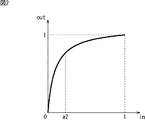
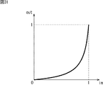
- FIG. 1 An example of a method for brightening an image to emphasize a main subject is to apply a gain to a signal.
- An example of characteristics when gain is applied is as shown in FIG.
- the horizontal axis represents the value (level) of the input signal
- the vertical axis represents the value (level) of the output signal.
- the signal is assumed to take a value of 0 to 1.
- whiteout occurs in a portion where the input signal is a1 (0 ⁇ a1 ⁇ 1) or more.
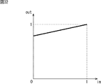
- a tone curve as shown in FIG. 2 is applied to a signal.
- overexposure as shown in FIG. 1 does not occur, but in the portion where the slope of the tone curve is smaller than 1, that is, the portion where the input signal is a2 (0 ⁇ a2 ⁇ 1) or more. Contrast is lowered.
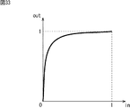
- the contrast can be increased as shown in FIG.
- blackout blocked up shadows
- whiteout occurs when the input signal is higher than b3. Will occur.
- the contrast enhancement is a normal contrast adjustment and enhances the output gain with respect to the input.
- adaptive contrast adjustment In order to reduce overexposure and underexposure due to normal contrast enhancement as described above, it is effective to optimize the contrast enhancement characteristics for each part of the image. Such processing is referred to as adaptive contrast adjustment in this specification.
- FIG. 4 is a block diagram illustrating an embodiment of an image processing apparatus to which the present technology is applied.
- an image processing apparatus 100 that enhances a predetermined portion of an image using tone curve adjustment and adaptive contrast adjustment is shown.
- the image processing apparatus 100 is configured to include a main part image processing unit 111-1, a background part image processing unit 111-2, and an image composition unit 112.
- the input image signal IN is supplied from the preceding stage (not shown) to the main image processing unit 111-1 and the background image processing unit 111-2.
- the main image processor 111-1 performs image processing using tone curve adjustment and adaptive contrast adjustment on the main subject region in the image of the input image signal IN.
- tone curve adjustment is performed to brighten the main part.
- the main image processing unit 111-1 supplies the image signal after the image processing to the image composition unit 112.
- the background image processing unit 111-2 performs image processing using tone curve adjustment and adaptive contrast adjustment on other regions other than the main subject in the image of the input image signal IN. In the background image processing unit 111-2, for example, tone curve adjustment for darkening the background portion is performed. The background image processing unit 111-2 supplies the image signal after the image processing to the image composition unit 112.
- the background image processing unit 111-2 may not perform image processing or may perform image processing. Conversely, when image processing is performed by the background image processing unit 111-2, the main image processing unit 111-1 may not perform image processing or may perform image processing. . That is, in the image processing apparatus 100, image processing is performed by at least one of them according to the degree of enhancement of the main subject.
- the main image processing unit 111-1 and the background image processing unit 111-2 are basically the same, although the processing target area, parameter values (characteristics), and effects required for the image are different. It is supposed to be configured. Therefore, hereinafter, the main part image processing unit 111-1 and the background part image processing unit 111-2 are collectively referred to as each part image processing unit 111 unless it is particularly necessary to distinguish between them.
- the image composition unit 112 uses an image (referred to as a main part image) from the main part image processing unit 111-1 for the main subject area, and the background part image processing unit 111-2 for the other areas. Is used to create a composite image. Note that the boundary portion between the main subject area and the other area may be combined so that the main image and the background image gradually change.
- the image composition unit 112 supplies the generated composite image signal as an output image signal OUT to a subsequent stage (not shown).
- the image composition unit 112 has been described as an example of composition for each picture. However, for example, it is also possible to configure the image composition unit 112 as a switch, and for each pixel, switch either the main part image or the background part image according to the region and output it to the subsequent stage. It is.
- FIG. 5 is a block diagram showing the configuration of the image processing unit for each unit.
- the common parts of the main image processing unit 111-1 and the background image processing unit 111-2 will be described together.
- a configuration example of each of the main image processing unit 111-1 and the background image processing unit 111-2 will be described later with reference to FIGS.
- the image processing unit 111 for each unit is configured to include a tone curve adjusting unit 121 and an adaptive contrast adjusting unit 122.
- the tone curve adjustment unit 121 adjusts the tone curve for the region to be the target of the input image signal IN, and supplies the image signal on which the tone curve has been adjusted to the adaptive contrast adjustment unit 122.
- the adaptive contrast adjustment unit 122 performs adaptive contrast adjustment on the region that is the target of the image whose tone curve has been adjusted by the tone curve adjustment unit 121.
- the adaptive contrast adjustment unit 122 supplies the output image signal OUT after the adaptive contrast processing to the subsequent stage.
- the adaptive contrast adjustment unit 122 is configured to include a local level detection unit 131 and a contrast adjustment unit 132 in the example of FIG.
- the local level detection unit 131 obtains the level of the peripheral region of the target pixel (hereinafter referred to as a local level), and is configured by, for example, a low-pass filter.
- the local level detection unit 131 may not be a low-pass filter as long as the local level can be extracted.
- the lower the cutoff frequency of the low-pass filter the lower the contrast of the low band.
- a filter that averages a region larger than about 1/100 (area ratio) of the image size is suitable.
- a filter size of about 1/10 to 1/2 of the short side size of the image is preferable. If it is smaller than that, it becomes close to detail emphasis and the contrast emphasis effect is weak. On the other hand, if it is larger than that, it becomes close to uniform contrast enhancement in the screen, and does not become adaptive contrast enhancement.
- the above sizes specifically, for example, about 1/5 of the short side size of the image is more preferable.
- the local level detection unit 131 outputs the obtained local level signal (for example, the average value of the local levels) to the subtracter 141 of the contrast adjustment unit 132.
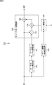
- the contrast adjustment unit 132 subtracts the local level signal from the image signal on which the tone curve has been adjusted, and adds the result to the image signal on which the tone curve has been adjusted to obtain an output image signal OUT. Is.
- the contrast adjustment unit 132 includes a subtracter 141 and an adder 142. That is, the subtractor 141 subtracts the local level signal from the image signal on which the tone curve has been adjusted, and outputs the result to the adder 142.
- the adder 142 adds the subtraction result of the subtracter 141 to the image signal whose tone curve has been adjusted, and outputs the output image signal OUT as a result thereof to the subsequent stage.
- the processing characteristics of the contrast adjustment unit 132 will be described with reference to FIGS.
- the local level L is small.
- the characteristics shown in FIG. 7 are obtained, and the contrast adjustment unit 132 performs contrast enhancement with a small blackout range and a large overexposure range. Done.
- contrast adjustment can be performed in which blackout and overexposure hardly occur.
- the local level L is medium. Therefore, for example, the characteristics shown in FIG. 8 are obtained.
- the blackout range and the whiteout range are the same. Some degree of contrast enhancement is performed. However, in this case, since the image signal is an intermediate region, the blackout range and overexposure range are small, and as a result, contrast enhancement in which blackout and overexposure hardly occur can be performed.
- the contrast adjustment unit 132 performs contrast enhancement with a large blackout range and a small overexposure range. Done.
- the image signal is large, there are few signals in the blackout range, and as a result, it is possible to perform contrast adjustment in which blackout and whiteout hardly occur.
- the contrast adjustment unit 132 performs adaptive contrast enhancement according to the local level from the local level detection unit 131. As a result, it is possible to perform contrast adjustment that is less likely to cause overexposure and underexposure.
- FIG. 10 is a block diagram illustrating a configuration example of the tone curve adjusting unit in FIG.
- the tone curve adjustment unit 121 is configured to include a D (Dynamic) range adjustment unit 151 and a signal distribution adjustment unit 152.
- the D range adjustment unit 151 adjusts the dynamic range of the image of the input image signal IN.
- the D range adjustment unit 151 supplies the image signal with the adjusted dynamic range of the image to the signal distribution adjustment unit 152.
- the D range adjustment unit 151 detects the distribution of the image signal and adjusts the signal level so that the dynamic range can be utilized effectively. Note that the detection of the distribution of the image signal may be performed on the entire screen or limited to a specific area.
- the signal distribution adjustment unit 152 adjusts the signal distribution of the image signal and enhances the image.
- the enhanced image is supplied to the adaptive contrast adjustment unit 122.
- the signal distribution adjustment unit 152 raises the average value of the signal level to make it brighter.
- An example highlighting (region) is shown.
- the image signal emphasized by the signal distribution adjustment unit 152 as described above is supplied to the adaptive contrast adjustment unit 122.
- the input image signal IN is supplied from the preceding stage (not shown) to the main image processing unit 111-1 and the background image processing unit 111-2.
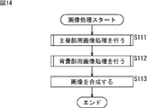
- step S111 the main image processing unit 111-1 performs main image processing.
- step S112 the background image processing unit 111-2 performs background image processing.
- the image processing for main part and the image processing for background part will be described in detail later with reference to FIG. 15 as the image processing for each part.
- step S111 image processing using tone curve adjustment and adaptive contrast adjustment is performed on the region of the main subject, and the image signal after the image processing is supplied to the image composition unit 112.
- step S112 image processing using tone curve adjustment and adaptive contrast adjustment is performed on the region other than the main subject, and the image signal after the image processing is supplied to the image composition unit 112. Is done.
- steps S111 and S112 may be performed in parallel. Alternatively, either one may be performed by external control or the like, and the input image signal IN may be supplied to the image composition unit 112 as it is on the other.
- step S113 the image composition unit 112 synthesizes images. That is, the image composition unit 112 creates a composite image using the main part image from the main part image processing unit 111-1 and the background image from the background part image processing unit 111-2. The generated composite image signal is supplied as an output image signal OUT to a subsequent stage (not shown).
- step S131 the D range adjustment unit 151 adjusts the dynamic range of the image of the input image signal IN.
- the D range adjustment unit 151 supplies the image signal whose dynamic range has been adjusted to the signal distribution adjustment unit 152.
- step S132 the signal distribution adjustment unit 152 adjusts the signal distribution of the image signal to enhance the image. For example, the adjustment of emphasizing the main subject region is performed by raising the average value of the signal level to make it brighter.
- the enhanced image is supplied to the adaptive contrast adjustment unit 122.
- step S133 the local level detection unit 131 detects a local level that is the level of the peripheral region of the target pixel.
- the local level detection unit 131 outputs the detected local level signal (for example, an average value of local levels) to the contrast adjustment unit 132.
- step S134 the contrast adjustment unit 132 subtracts the local level signal from the image signal on which the tone curve has been adjusted, and adds the result to the image signal on which the tone curve has been adjusted, thereby outputting an output image.
- the contrast is adjusted by obtaining the signal OUT.
- the subtracter 141 subtracts the local level signal from the image signal on which the tone curve has been adjusted, and outputs the result to the adder 142.
- the adder 142 adds the subtraction result of the subtracter 141 to the image signal whose tone curve has been adjusted, and outputs the output image signal OUT as a result thereof to the subsequent stage.
- adaptive contrast adjustment is performed according to the detected local level, so that contrast enhancement that hardly causes blackout and overexposure is performed. be able to. Furthermore, since the enhancement is performed after the main subject region is emphasized, the main subject can be made more prominent in the image.
- FIG. 16 is a block diagram illustrating another configuration example of the adaptive contrast adjustment unit in FIG.
- the adaptive contrast adjustment unit 122 is configured to include a local level detection unit 131, a local level adjustment unit 161, a contrast adjustment unit 162, a gain adjustment coefficient setting unit 163, and a gain adjustment unit 164. Yes.
- 16 is similar to the adaptive contrast adjustment unit 122 in FIG. 5 in that the adaptive contrast adjustment unit 122 in FIG.
- the adaptive contrast adjusting unit 122 in FIG. 16 is different from the adaptive contrast adjusting unit 122 in FIG. 5 in that the contrast adjusting unit 132 is replaced with a contrast adjusting unit 162.
- the adaptive contrast adjusting unit 122 in FIG. 16 is different from the adaptive contrast adjustment unit 122 in FIG. 5 in that it includes a local level adjustment unit 161, a gain adjustment coefficient setting unit 163, and a gain adjustment unit 164.
- the local level signal from the local level detection unit 131 is supplied to the local level adjustment unit 161.
- the local level adjustment unit 161 adjusts the local level obtained by the local level detection unit 131.
- the local level adjustment unit 161 supplies the adjusted local level signal to the contrast adjustment unit 162.
- the contrast adjustment unit 162 subtracts the local level signal from the image signal on which the tone curve has been adjusted, adds the gain to the result, and adds the result to the image signal on which the tone curve has been adjusted. An output image signal OUT is obtained.
- the contrast adjustment unit 162 includes the subtracter 141 and the adder 142, and is the same as the contrast adjustment unit 132 in FIG.
- the contrast adjustment unit 162 is different from the contrast adjustment unit 132 of FIG. 5 in that a multiplier 171 for multiplying the gain from the gain adjustment unit 164 is added.
- the subtracter 141 subtracts the local level signal from the image signal on which the tone curve has been adjusted, and outputs the result to the multiplier 171.
- the multiplier 171 multiplies the result subtracted by the subtracter 141 by the gain from the gain adjustment unit 164.
- the multiplier 171 outputs the result multiplied by the gain to the adder 142.
- the adder 142 adds the gain multiplication result by the multiplier 171 to the image signal whose tone curve has been adjusted, and outputs the resultant output image signal OUT to the subsequent stage.
- the input image signal IN from the previous stage is supplied to the local level detection unit 131 and the gain adjustment coefficient setting unit 163.
- the gain adjustment coefficient setting unit 163 obtains and sets a coefficient for adjusting the gain according to the input image signal IN, and supplies the set coefficient to the gain adjustment unit 164.
- the gain adjustment unit 164 adjusts the gain by multiplying the preset gain G by the coefficient obtained by the gain adjustment coefficient setting unit 163.
- the gain adjusted by the gain adjusting unit 164 is supplied to the multiplier 171 of the contrast adjusting unit 162.
- the local level adjustment unit 161 will be described.
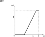
- the solid line represents an example of the characteristics of the local level adjustment unit 161.
- the local level adjustment unit 161 makes the level of the output signal (hereinafter referred to as the output level) smaller than the input level. Further, the local level adjustment unit 161 makes the output level larger than the input level when the input level is larger than b.
- the local level L shown in FIG. 7 is shifted to a smaller direction, and blackout is further reduced. become.
- the local level becomes larger, so that the local level L shown in FIG. 9 is shifted in the larger direction, and the overexposure is further reduced.
- the characteristics of the local level adjustment unit 161 are expressed as a solid line in the example of FIG. 18, for example.
- b is set smaller than in the example of FIG.
- the characteristic of the local level adjustment unit 161 is represented as a solid line in FIG. 19, for example.
- b is set larger than in the example of FIG.
- the local level of the image (for example, the average value of the local region) is adjusted with time according to the bias of the luminance distribution.
- the gain adjustment coefficient setting unit 163 Next, the gain adjustment coefficient setting unit 163 will be described.
- the solid line represents an example of the characteristics of the gain adjustment coefficient setting unit.
- the characteristics of the gain adjustment coefficient setting unit 163 are determined in consideration of the characteristics of the signal distribution adjustment unit 152. As described above, as a result of the signal distribution adjustment, the contrast decreases as the slope of FIG. 13 is smaller (that is, the signal level is higher). Therefore, by providing the gain adjustment coefficient setting unit 163 with a characteristic proportional to the inverse of the derivative of the characteristic in FIG. 13, the total contrast enhancement characteristic becomes constant. As a result, it is possible to reduce blackout when the gain is increased.
- step S161 the D range adjustment unit 151 adjusts the dynamic range of the image of the input image signal IN.
- the D range adjustment unit 151 supplies the image signal with the adjusted dynamic range of the image to the signal distribution adjustment unit 152.
- step S162 the signal distribution adjustment unit 152 adjusts the signal distribution of the image signal to enhance the image. For example, the adjustment of emphasizing the main subject region is performed by raising the average value of the signal level to make it brighter.
- the enhanced image is supplied to the adaptive contrast adjustment unit 122.
- step S163 the local level detection unit 131 detects a local level that is the level of the peripheral region of the target pixel.
- the local level detection unit 131 outputs the detected local level signal to the local level adjustment unit 161.
- step S164 the local level adjustment unit 161 adjusts the local level obtained by the local level detection unit 131.
- the local level adjustment unit 161 supplies the adjusted local level signal to the contrast adjustment unit 162.
- step S165 the gain adjustment coefficient setting unit 163 obtains and sets a coefficient for adjusting the gain according to the input image signal IN from the signal distribution adjustment unit 152, and supplies the set coefficient to the gain adjustment unit 164. .
- step S166 the gain adjustment unit 164 adjusts the gain by multiplying the preset gain G by the coefficient obtained by the gain adjustment coefficient setting unit 163.
- the gain adjusted by the gain adjusting unit 164 is supplied to the multiplier 171 of the contrast adjusting unit 162.
- step S167 the contrast adjustment unit 162 subtracts the local level signal from the image signal on which the tone curve has been adjusted. Then, the contrast adjusting unit 162 adds the gain obtained by multiplying the result to the image signal on which the tone curve has been adjusted to obtain the output image signal OUT, thereby adjusting (emphasizing) the contrast.
- the subtracter 141 subtracts the local level signal from the image signal on which the tone curve has been adjusted, and outputs the result to the multiplier 171.
- the multiplier 171 multiplies the result subtracted by the subtracter 141 by the gain from the gain adjustment unit 164.
- the multiplier 171 outputs the result multiplied by the gain to the adder 142.
- the adder 142 adds the gain multiplication result by the multiplier 171 to the image signal whose tone curve has been adjusted, and outputs the resultant output image signal OUT to the subsequent stage.
- FIG. 23 is a block diagram illustrating another embodiment of an image processing apparatus to which the present technology is applied.
- the image processing apparatus 200 of FIG. 23 is common to the image processing apparatus 100 of FIG. 4 in that it includes a main part image processing unit 111-1, a background part image processing unit 111-2, and an image composition unit 112. Yes.
- the image processing apparatus 200 of FIG. 23 is different from the image processing apparatus 100 of FIG. 4 in that a main subject region setting unit 211 is added.
- the main subject area setting unit 211 detects a main subject in the image and sets a main subject area assumed from the detected main subject information.
- the main subject area setting unit 211 detects the main subject in the image.
- face detection is used assuming that the main subject is a person is taken as an example.
- face area information is obtained by face detection and used as main subject information. It is also possible for the user to set the main subject area.
- the main subject area setting unit 211 sets a main subject area assumed from the main subject information.
- main subject detection is face detection
- a human region assumed from the face region is set as the main subject region.
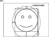
- an ellipse (major axis a + b + 2c, minor axis a + 2c) whose diameter is a size obtained by adding an additional value c to the size of the area obtained by adding the extended area b to the face area a is the main subject area.
- An example is shown. This is a case where the subject appears relatively small, and the extended region b is set to include the vicinity of the trunk.
- an ellipse (major axis a + b + 2c, minor axis a + 2c) having a diameter obtained by adding an additional value c to the size of the area obtained by adding the extended area b to the face area a is mainly used.
- An example of a subject area is shown. This is a case where the subject is relatively large, and the extended region b is set so as to include the vicinity of the neck.
- the extended region b is included up to the vicinity of the chest.
- the expansion amount from the face area to the trunk direction is set to be larger as the face size is smaller.
- such a characteristic is indicated by a solid line.
- the additional value c is substantially constant regardless of the face size.
- the main subject region When there are a plurality of main subjects, a combination of these regions may be used as the main subject region, or any one of them may be selected as the main subject region.
- the main subject region When the main subject is not detected, the main subject region may be set near the center of the screen. Furthermore, even when the main subject is detected, the area may be expanded toward the center of the screen when it is biased toward the edge of the screen. Further, the detected main subject may be used as the main subject region without expanding the main subject (that is, the detected region may be used as the main subject region).
- boundary blurring may be performed on this main subject area by a low-pass filter or the like.
- the input image signal IN is supplied to the main subject region setting unit 211, the main image processing unit 111-1, and the background image processing unit 111-2 from the preceding stage (not shown).
- step S211 the main subject area setting unit 211 detects the main subject of the image of the input image signal IN.
- face area information is obtained by face detection and used as main subject information.
- step S212 the main subject region setting unit 211 sets a main subject region assumed from the main subject information. For example, when the main subject detection is face detection, a person region assumed from the face region is set as the main subject region.
- step S213 the main part image processing unit 111-1 performs main part image processing.
- step S214 the background image processing unit 111-2 performs background image processing.
- the image processing for main part and the image processing for background part are basically the same as the image processing for each part described above with reference to FIG. Is done.
- step S213 image processing using tone curve adjustment and adaptive contrast adjustment is performed on the region of the main subject, and the image signal after the image processing is supplied to the image composition unit 112.
- step S214 image processing using tone curve adjustment and adaptive contrast adjustment is performed on regions other than the main subject, and the image signal after image processing is supplied to the image composition unit 112. Is done.
- steps S213 and S214 may be performed in parallel, or one of them is performed by external control or the like.
- IN may be supplied to the image composition unit 112 as it is.
- step S215 the image composition unit 112 composes an image.
- the image composition unit 112 creates a composite image using the main part image from the main part image processing unit 111-1 and the background part image from the background part image processing unit 111-2.
- the generated composite image signal is supplied as an output image signal OUT to a subsequent stage (not shown).
- FIG. 28 is a diagram showing a configuration pattern of the main image processing unit 111-1.
- the main image processing unit 111-1 creates an image that gives a distinctive impression by brightening the image and enhancing the contrast.
- Main part image processing section 111-1 includes, as configuration 1, D range adjustment section 151, signal distribution adjustment section 152, and adaptive contrast adjustment section 122 as described above with reference to FIGS. Configured as follows.
- the D range adjustment unit 151 detects the image signal distribution for the main subject region of the image and adjusts the dynamic range as described above with reference to FIGS.
- the signal distribution adjustment unit 152 enhances the image (its main subject area) by, for example, raising the average value of the signal level using the characteristic shown in FIG.
- the adaptive contrast adjustment unit 122 performs contrast enhancement with less overexposure by performing adaptive contrast enhancement, for example, as described above with reference to FIGS.
- the D range adjustment unit 151 is not an essential configuration requirement.
- the main image processing unit 111-1 is configured to include a signal distribution adjustment unit 152 and an adaptive contrast adjustment unit 122 as configuration 2.
- the D range adjustment is effective when the luminance distribution of the original image is narrow.
- adjusting the D range will make the image look hazy. That is, if the image having a narrower luminance distribution range is configured as 1, the image becomes clearer.
- the configuration of the main image processing unit 111-1 is normally configuration 2, and is automatically switched to configuration 1 when the luminance distribution range of the image is narrow.
- the characteristics shown in FIGS. 7 to 9 are automatically switched according to the output level L of the low-pass filter serving as the local level detection unit 131.
- the characteristics shown in FIGS. 17 to 19 are usually the characteristics shown in FIG. Further, when the luminance distribution is biased toward high luminance, the characteristic of FIG. 18 is switched with emphasis on over-exposure reduction, and when the luminance distribution is biased toward low luminance, emphasis is placed on black solid reduction. Switch to characteristics.
- FIG. 29 is a diagram showing a configuration pattern of the background image processing unit 111-2.
- the background image processing unit 111-2 creates an image in which the main part gives a more distinctive impression by enhancing contrast while darkening the image. Note that just darkening the background has the effect of making the main parts stand out, but further emphasizing the contrast makes it possible to create brighter parts in the dark, resulting in an effect resembling painting expression by the light and dark method.
- background image processing unit 111-2 includes D range adjustment unit 151, signal distribution adjustment unit 152, and adaptive contrast adjustment unit 122 as described above with reference to FIGS. Configured as follows.
- the configuration is the same as that of the main image processing unit 111-1 described above with reference to FIG. 28, but their characteristics (parameter characteristics) are different.
- the D range adjustment unit 151 detects the image signal distribution for the main subject region of the image or the entire image, and adjusts the dynamic range as described above with reference to FIGS.
- the signal distribution adjustment unit 152 darkens the signal level by reducing the signal level using, for example, characteristics as shown in FIG.
- the adaptive contrast adjustment unit 122 performs contrast enhancement with less overexposure by performing adaptive contrast enhancement as described above, for example.
- the D range adjustment unit 151 is not an essential configuration requirement. That is, in the case of the configuration 2-1, the D range adjustment unit 151 does not normally operate and allows the signal to pass through.
- the adaptive contrast adjustment unit 122 other than the D range adjustment unit 151 does not work. Also good. In other words, contrast enhancement for areas other than the main subject may be prohibited. That is, in this case, for example, the signal distribution adjustment unit 152 enhances the contrast by reducing the signal level by using the characteristics as shown in FIG. 31 and making the originally bright part not so dark. Because you can.
- the characteristic of the signal distribution adjusting unit 152 is set to be very bright by changing the intercept of the linear function in the plus direction as shown in FIG. 32, for example, the background is darkened.
- the main subject emphasis effect can be obtained by brightening the background.
- the configuration of the background image processing unit 111-2 is usually the configuration 2-1 (or configuration 2-2), and the luminance distribution range of the image. Automatically switches to configuration 1 when the
- FIG. 30 or 31 and FIG. 32 are switched to FIG. 30 or FIG. 31 when the background is darker than a certain level, and when the background is brighter than a certain level, It switches to FIG.
- the characteristics shown in FIGS. 20 and 21 are switched to FIG. 20 when the low luminance component is large, and when the low luminance component is small, the characteristics shown in FIG. Can be switched.
- image processing for enhancing an image is applied to a luminance signal.
- a gain corresponding to the resulting luminance change to the color signal. That is, if the luminance signal changes from Yin to Yout, a color signal suitable for the luminance signal can be obtained by applying a gain of Yout / Yin to the color signal.
- a process of erasing only the background portion of the color difference signal may be performed.
- the main subject stand out by making contrast enhancement while making the main subject region brighter. Further, the main subject can be made more conspicuous by performing contrast enhancement while darkening the background region other than the main subject region.
- the present technology is applied not only to the image processing device but also to an imaging device, a server, and the like.
- the imaging apparatus, or the server for example, the following processing modes are provided, and each processing unit constituting the main part or background part image processing unit described above according to the shooting mode. It is possible to set the characteristics.
- the low contrast mode is a mode used in the case of an image with overcast or haze. When this mode is selected, the processing of the D range adjustment unit 151 is performed.
- the subject exposure under mode is a mode selected when the subject (main part) is darker than usual because the background is bright.
- this mode is selected, the effect of brightening in the signal distribution adjusting unit 152 of the main image processing unit 111-1 is strengthened as shown in the characteristics shown in FIG.
- blackout reduction is emphasized.
- the subject part overexposure mode is selected when the background is dark and the subject part is brighter than usual.
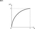
- this mode is selected, the effect of brightening in the signal distribution adjusting unit 152 of the main image processing unit 111-1 is weakened as shown in the characteristics shown in FIG.
- the setting of emphasis on overexposure is made.
- the normal mode darkens the background, while the background skipping (background white skipping) mode is selected when the image wants to whiten the background.
- the signal distribution adjusting unit 152 of the background image processing unit 111-2 has a very bright characteristic. At this time, the gain applied to the color signal of the background portion is reduced to perform achromatic processing.
- the above four shooting modes can be selected by the user, and automatic mode setting can also be performed by image processing or the like.
- the difference between the characteristics shown in FIG. 30 or 31 and the characteristics shown in FIG. 32 is whether the background is dark or bright. Therefore, when the background is darker than a certain level, the characteristics shown in FIG. 30 or FIG. 31 can be used. When the background is brighter than a certain level, the characteristics shown in FIG. 32 can be used.
- the main image processing unit 111-1, the background image processing unit 111-2, and the image processing unit are divided into two.
- the configuration is not limited thereto.
- the processing may be switched in one image processing unit without dividing the image processing unit, and the main image and the background image may be processed.
- the series of processes described above can be executed by hardware or software.
- a program constituting the software is installed in the computer.
- the computer includes, for example, a general-purpose personal computer capable of executing various functions by installing various programs by installing a computer incorporated in dedicated hardware.
- FIG. 35 shows an example of the hardware configuration of a computer that executes the above-described series of processing by a program.
- a CPU Central Processing Unit
- ROM Read Only Memory
- RAM Random Access Memory
- an input / output interface 805 is connected to the bus 804.
- An input unit 806, an output unit 807, a storage unit 808, a communication unit 809, and a drive 810 are connected to the input / output interface 805.
- the input unit 806 includes a keyboard, a mouse, a microphone, and the like.
- the output unit 807 includes a display, a speaker, and the like.
- the storage unit 808 includes a hard disk, a nonvolatile memory, and the like.
- the communication unit 809 includes a network interface or the like.
- the drive 810 drives a removable recording medium 811 such as a magnetic disk, an optical disk, a magneto-optical disk, or a semiconductor memory.
- the CPU 801 loads the program stored in the storage unit 808 to the RAM 803 via the input / output interface 805 and the bus 804 and executes the program, for example. Is performed.
- the program executed by the computer (CPU 801) can be provided by being recorded in a removable recording medium 811 as a package medium, for example.
- the program can be provided via a wired or wireless transmission medium such as a local area network, the Internet, or digital satellite broadcasting.
- the program can be installed in the storage unit 808 via the input / output interface 805 by attaching the removable recording medium 811 to the drive 810.
- the program can be received by the communication unit 809 via a wired or wireless transmission medium and installed in the storage unit 808.
- the program can be installed in the ROM 802 or the storage unit 808 in advance.
- the program executed by the computer may be a program that is processed in time series in the order described in this specification, or in parallel or at a necessary timing such as when a call is made. It may be a program for processing.
- steps describing the series of processes described above are not limited to the processes performed in time series according to the described order, but are not necessarily performed in time series, either in parallel or individually.
- the process to be executed is also included.
- the present technology can take a configuration of cloud computing in which one function is shared by a plurality of devices via a network and is jointly processed.
- each step described in the above flowchart can be executed by one device or can be shared by a plurality of devices.
- the plurality of processes included in the one step can be executed by being shared by a plurality of apparatuses in addition to being executed by one apparatus.
- the configuration described as one device (or processing unit) may be divided and configured as a plurality of devices (or processing units).
- the configurations described above as a plurality of devices (or processing units) may be combined into a single device (or processing unit).
- a configuration other than that described above may be added to the configuration of each device (or each processing unit).
- a part of the configuration of a certain device (or processing unit) may be included in the configuration of another device (or other processing unit). . That is, the present technology is not limited to the above-described embodiment, and various modifications can be made without departing from the gist of the present technology.
- this technique can also take the following structures.
- a tone curve adjusting unit that performs tone curve adjustment on at least one of the main subject region of the image and another region other than the main subject region;
- An image processing apparatus comprising: a contrast adjustment unit that performs contrast enhancement on a region in which tone curve adjustment has been performed by the tone curve adjustment unit.
- the image processing apparatus according to (1) wherein the tone curve adjustment unit performs tone curve adjustment that brightens the main subject region.
- the tone curve adjustment unit performs tone curve adjustment to brighten the main subject region after adjusting the dynamic range.
- the tone curve adjustment unit performs tone curve adjustment that brightens the main subject area according to the brightness of the other area.
- the image processing device (9) The image processing device according to (6), wherein the tone curve adjustment unit performs tone curve adjustment that darkens or brightens the other region in accordance with a user operation. (10) The image processing device according to (6), wherein the tone curve adjustment unit performs tone curve adjustment that darkens a portion other than the bright portion of the other region. (11) The contrast adjustment unit prohibits contrast enhancement for the other region when the other region is included in the region on which the tone curve adjustment is performed by the tone curve adjustment unit. An image processing apparatus according to 1. (12) The image processing device according to any one of (1) to (11), wherein the tone curve adjustment unit performs tone curve adjustment that brightens the main subject region and darkens the other region.
- the image processing device performs contrast enhancement in which a contrast enhancement characteristic is variable for each region according to an average value of local regions of the image.
- the contrast adjustment unit includes: A local level adjustment unit for adjusting an average value of a local region of the image; The image processing apparatus according to (13), wherein contrast enhancement is performed by changing a contrast enhancement characteristic for each region based on an average value of local regions of the image adjusted by the local level adjustment unit.
- the local level adjustment unit adjusts an average value of a local region of the image with a characteristic according to a bias of a luminance distribution.
- the image processing device (16) The image processing device according to (14), wherein the local level adjustment unit adjusts an average value of a local region of the image according to a user operation.
- the main subject region includes a face region and a region expanded from the face region toward the trunk.
- the amount of expansion decreases as the size of the face area increases.
- the image processing apparatus Perform tone curve adjustment on at least one of the main subject region of the image and the other region other than the main subject region, An image processing method in which contrast enhancement is performed on an area on which the tone curve adjustment has been performed.
- tone curve adjustment unit that performs tone curve adjustment on at least one of the main subject region of the image and another region other than the main subject region;
- a program that causes a computer to function as a contrast adjustment unit that performs contrast enhancement on an area in which tone curve adjustment has been performed by the tone curve adjustment unit.
- 100 image processing device 111 image processing unit for each part, 111-1 main image processing unit, 111-2 background image processing unit, 112 image composition unit, 121 tone curve adjustment unit, 122 adaptive contrast adjustment unit, 131 local level detection unit, 132 contrast adjustment unit, 141 subtractor, 142 adder, 151 D range adjustment unit, 152 signal distribution unit, 161 local level adjustment unit, 162 contrast adjustment unit, 163 gain adjustment coefficient setting unit, 164 gain Adjustment section, 200 main subject area setting section
Landscapes
- Engineering & Computer Science (AREA)
- Multimedia (AREA)
- Health & Medical Sciences (AREA)
- Oral & Maxillofacial Surgery (AREA)
- Signal Processing (AREA)
- Physics & Mathematics (AREA)
- General Physics & Mathematics (AREA)
- Theoretical Computer Science (AREA)
- General Health & Medical Sciences (AREA)
- Computer Vision & Pattern Recognition (AREA)
- Human Computer Interaction (AREA)
- Image Processing (AREA)
Abstract
本開示は、画像において主要被写体をより際立たせることができるようにする画像処理装置、画像処理方法、およびプログラムに関する。 トーンカーブ調整部は、入力画像信号INの対象となる領域に対して、トーンカーブの調整を行い、トーンカーブの調整が行われた画像信号を、ローカルレベル検出部に供給する。ローカルレベル検出部は、ローカルレベルを求める。コントラスト調整部は、ローカルレベル検出部からのローカルレベルに応じた適応的なコントラスト強調を行う。本開示は、例えば、トーンカーブ調整と適応的コントラスト調整とを用いて画像の所定部分を強調する画像処理装置に適用することができる。
Description
本開示は、画像処理装置、画像処理方法、およびプログラムに関し、特に、画像において主要被写体をより際立たせることができるようにした画像処理装置、画像処理方法、およびプログラムに関する。
画像の主要被写体領域の明るさや色を調整し、主要被写体を他の部分より強調することで好ましい画像を得る方法がある。
例えば、特許文献1には、主要被写体領域の画像信号を解析し、画像全体に対してそれに適した強調特性を設定し、強調処理を行う方法が開示されている。
しかしながら、画像を強調することで、画像に破綻をきたすことがある。例えば、画像に対して明るさを増すことで、白く飛んでしまう部分が発生してしまうことがある。また、逆に、特許文献1に記載の提案では、画像によっては十分な効果が得られないことがある。
本開示は、このような状況に鑑みてなされたものであり、画像において主要被写体をより際立たせることができるものである。
本開示の一側面の画像処理装置は、画像の主要被写体領域および前記主要被写体領域以外の領域である他の領域の少なくとも一方の領域にトーンカーブ調整を行うトーンカーブ調整部と、前記トーンカーブ調整部によりトーンカーブ調整が行われた領域に対して、コントラスト強調を行うコントラスト調整部とを備える。
前記トーンカーブ調整部は、前記主要被写体領域を明るくするトーンカーブ調整を行うことができる。
前記トーンカーブ調整部は、ダイナミックレンジの調整後、前記主要被写体領域を明るくするトーンカーブ調整を行うことができる。
前記トーンカーブ調整部は、前記他の領域の明るさに応じて、前記主要被写体領域を明るくするトーンカーブ調整を行うことができる。
前記トーンカーブ調整部は、ユーザの操作に応じて、前記主要被写体領域を明るくするトーンカーブ調整を行うことができる。
前記トーンカーブ調整部は、前記他の領域を暗くするトーンカーブ調整を行うことができる。
前記トーンカーブ調整部は、ダイナミックレンジの調整後、前記他の領域を暗くするトーンカーブ調整を行うことができる。
前記トーンカーブ調整部は、前記他の領域の明るさに応じて、前記他の領域を暗く、または明るくするトーンカーブ調整を行うことができる。
前記トーンカーブ調整部は、ユーザの操作に応じて、前記他の領域を暗く、または明るくするトーンカーブ調整を行うことができる。
前記トーンカーブ調整部は、前記他の領域の明るい部分以外の部分を暗くするトーンカーブ調整を行うことができる。
前記コントラスト調整部は、前記トーンカーブ調整部によりトーンカーブ調整が行われた領域に前記他の領域が含まれる場合、前記他の領域に対してのコントラスト強調を禁止することができる。
前記トーンカーブ調整部は、前記主要被写体領域を明るくし、前記他の領域を暗くするトーンカーブ調整を行うことができる。
前記コントラスト調整部は、前記画像の局所領域の平均値によって領域毎にコントラスト強調特性を可変としたコントラスト強調を行うことができる。
前記コントラスト調整部は、前記画像の局所領域の平均値を調整するローカルレベル調整部を備え、前記ローカルレベル調整部により調整された画像の局所領域の平均値によって領域毎にコントラスト強調特性を可変としたコントラスト強調を行うことができる。
前記ローカルレベル調整部は、輝度分布の偏りに応じた特性で、前記画像の局所領域の平均値を調整することができる。
前記ローカルレベル調整部は、ユーザの操作に応じて、前記画像の局所領域の平均値を調整することができる。
前記主要被写体領域は、顔領域と前記顔領域から胴体方向に拡張が行われた領域とを含むことができる。
前記拡張の量は、前記顔領域のサイズ大きくなるほど小さくなる。
本開示の一側面の画像処理方法は、画像処理装置が、画像の主要被写体領域および前記主要被写体領域以外の領域である他の領域の少なくとも一方の領域にトーンカーブ調整を行い、前記トーンカーブ調整が行われた領域に対して、コントラスト強調を行う。
本開示の一側面のプログラムは、画像の主要被写体領域および前記主要被写体領域以外の領域である他の領域の少なくとも一方の領域にトーンカーブ調整を行うトーンカーブ調整部と、前記トーンカーブ調整部によりトーンカーブ調整が行われた領域に対して、コントラスト強調を行うコントラスト調整部としてコンピュータを機能させる。
本開示の一側面においては、画像の主要被写体領域および前記主要被写体領域以外の領域である他の領域の少なくとも一方の領域にトーンカーブ調整が行われる。そして、前記トーンカーブ調整が行われた領域に対して、コントラスト強調が行われる。
本開示によれば、画像のトーンカーブ調整とコントラスト強調を行うことができる。特に、本開示によれば、画像において主要被写体をより際立たせることができる。
以下、本開示を実施するための形態(以下実施の形態とする)について説明する。なお、説明は以下の順序で行う。
0.概要
1.第1の実施の形態(画像処理装置)
2.第2の実施の形態(画像処理装置)
3.第3の実施の形態(変形例)
4.第4の実施の形態(コンピュータ)
0.概要
1.第1の実施の形態(画像処理装置)
2.第2の実施の形態(画像処理装置)
3.第3の実施の形態(変形例)
4.第4の実施の形態(コンピュータ)
<0.概要>
[本技術の概要]
主要被写体を強調するために画像を明るくする方法の一例としては、信号にゲインをかけるものがある。ゲインをかける場合の特性例は、図1に示されるようなものである。図1の例においては、横軸が入力信号の値(レベル)を表し、縦軸が出力信号の値(レベル)を表している。なお、以下、信号は、0乃至1の値をとるものとする。
[本技術の概要]
主要被写体を強調するために画像を明るくする方法の一例としては、信号にゲインをかけるものがある。ゲインをかける場合の特性例は、図1に示されるようなものである。図1の例においては、横軸が入力信号の値(レベル)を表し、縦軸が出力信号の値(レベル)を表している。なお、以下、信号は、0乃至1の値をとるものとする。
図1の例においては、入力信号がa1(0<a1<1)以上の部分に白とび(blown out highlights)が発生することになる。
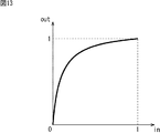
また、他の例としては、信号に対して、図2に示されるようなトーンカーブをかけるものもある。図2の例の場合、図1に示されたような白とびは発生しないが、トーンカーブの傾きが1よりも小さい部分、すなわち、入力信号がa2(0<a2<1)以上の部分では、コントラストが低下してしまう。
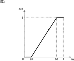
このような場合、図3に示されるように、コントラストを上げることが可能である。図3の例のようにコントラストを上げる場合、入力信号がa3(0<a3<b3<1)以下の部分では、黒つぶれ(blocked up shadows)が発生し、b3以上の部分では、白とびが発生することになる。
すなわち、白とびを抑制するために、図2に示されるようなトーンカーブを用いたとしてもコントラストが低下し、そのコントラストの低下を補正するために、図3に示されるようなコントラスト強調を行うと、結局、白とびが発生することになる。この場合のコントラスト強調は、通常のコントラスト調整であり、入力に対して出力のゲインを立てて強調するものである。
以上のような通常のコントラスト強調による白とびや黒つぶれを軽減するためには、コントラスト強調特性を、画像の部分毎に最適化することが有効となる。このような処理を、本明細書においては、適応的コントラスト調整と称する。
以下に、トーンカーブ調整と適応的コントラスト調整とを用いて画像の所定部分を強調する画像処理装置について説明する。
<1.第1の実施の形態>
[画像処理装置の構成例]
図4は、本技術を適用した画像処理装置の一実施の形態を示すブロック図である。図4の例においては、トーンカーブ調整と適応的コントラスト調整とを用いて画像の所定部分を強調する画像処理装置100が示されている。
[画像処理装置の構成例]
図4は、本技術を適用した画像処理装置の一実施の形態を示すブロック図である。図4の例においては、トーンカーブ調整と適応的コントラスト調整とを用いて画像の所定部分を強調する画像処理装置100が示されている。
画像処理装置100は、主要部用画像処理部111-1、背景部用画像処理部111-2、および画像合成部112を含むように構成されている。
図示せぬ前段から、主要部用画像処理部111-1および背景部用画像処理部111-2に、入力画像信号INが供給される。
主要部用画像処理部111-1は、入力画像信号INの画像における主要被写体の領域に対して、トーンカーブ調整と適応的コントラスト調整とを用いた画像処理を行う。主要部用画像処理部111-1においては、例えば、主要部を明るくするトーンカーブ調整が行われる。主要部用画像処理部111-1は、画像処理後の画像信号を、画像合成部112に供給する。
背景部用画像処理部111-2は、入力画像信号INの画像における主要被写体以外の領域である他の領域に対して、トーンカーブ調整と適応的コントラスト調整とを用いた画像処理を行う。背景部用画像処理部111-2においては、例えば、背景部を暗くするトーンカーブ調整が行われる。背景部用画像処理部111-2は、画像処理後の画像信号を、画像合成部112に供給する。
なお、主要部用画像処理部111-1により画像処理が行われるとき、背景部用画像処理部111-2は、画像処理を行わなくてもよいし、あるいは、画像処理を行ってもよい。逆に、背景部用画像処理部111-2により画像処理が行われるとき、主要部用画像処理部111-1は、画像処理を行わなくてもよいし、あるいは、画像処理を行ってもよい。すなわち、画像処理装置100においては、主要被写体の強調度合いに応じて、少なくともどちらか一方により画像処理が行われる。
また、主要部用画像処理部111-1および背景部用画像処理部111-2は、処理対象の領域、パラメータの値(特性)、および画像に求められる効果などが異なるが、基本的に同じ構成とされる。したがって、以下、特に区別する必要がない場合、主要部用画像処理部111-1および背景部用画像処理部111-2は、各部用画像処理部111と総称する。
画像合成部112は、主要被写体の領域については主要部用画像処理部111-1からの画像(主要部用画像と称する)を用い、それ以外の領域については背景部用画像処理部111-2からの画像(背景部用画像と称する)を用いて合成画像を作成する。なお、主要被写体の領域とそれ以外の領域の境界部分は、主要部用画像と背景部用画像を徐々に変化するように合成されてもよい。
画像合成部112は、作成した合成画像の信号を、出力画像信号OUTとして図示せぬ後段に供給する。
なお、図4の例においては、ピクチャ毎に合成する例として画像合成部112を説明した。しかしながら、例えば、画像合成部112をスイッチとして構成し、画素毎に、主要部用画像と背景部用画像のどちらかの画素を領域に応じて切り替えて、後段に出力するようにすることも可能である。
[各部用画像処理部の構成]
図5は、各部用画像処理部の構成を示すブロック図である。なお、図5の例においては、主要部用画像処理部111-1および背景部用画像処理部111-2の共通部分などに関してまとめて説明される。主要部用画像処理部111-1および背景部用画像処理部111-2のそれぞれの構成例は、図28および図29を参照して後述される。
図5は、各部用画像処理部の構成を示すブロック図である。なお、図5の例においては、主要部用画像処理部111-1および背景部用画像処理部111-2の共通部分などに関してまとめて説明される。主要部用画像処理部111-1および背景部用画像処理部111-2のそれぞれの構成例は、図28および図29を参照して後述される。
図5の例において、各部用画像処理部111は、トーンカーブ調整部121および適応的コントラスト調整部122を含むように構成されている。
トーンカーブ調整部121は、入力画像信号INの対象となる領域に対して、トーンカーブの調整を行い、トーンカーブの調整が行われた画像信号を、適応的コントラスト調整部122に供給する。
適応的コントラスト調整部122は、トーンカーブ調整部121によりトーンカーブの調整が行われた画像の対象となる領域に対して、適応的コントラスト調整を行う。適応的コントラスト調整部122は、適応的コントラスト処理が終わった出力画像信号OUTを後段に供給する。
適応的コントラスト調整部122は、図5の例において、ローカルレベル検出部131およびコントラスト調整部132を含むように構成されている。
ローカルレベル検出部131は、注目画素の周辺領域のレベル(以下、ローカルレベルと称する)を求めるものであり、例えば、ローパスフィルタで構成されている。ローカルレベル検出部131は、ローカルレベルを抽出できるものであれば、ローパスフィルタでなくてもよい。
ローカルレベル検出部131において、ローパスフィルタのカットオフ周波数が低いほど、より低域のコントラストが強調される。ローパスフィルタとしては、画像サイズの1/100程度(面積比)より大きな領域を平均化するフィルタが好適である。
例えば、図6に示されるように、画像の短辺サイズの1/10乃至1/2程度のフィルタサイズが好ましい。それより小さいと、ディテール強調に近くなり、コントラスト強調効果が弱い。また、それより大きいと、画面内均一のコントラスト強調に近くなり、適応的コントラスト強調にならない。なお、上記サイズの中でも、具体的には、例えば、画像の短辺サイズの1/5前後がより好適である。
ローカルレベル検出部131は、求められたローカルレベル信号(例えば、局所レベルの平均値)を、コントラスト調整部132の減算器141に出力する。
コントラスト調整部132は、トーンカーブの調整が行われた画像信号から、ローカルレベル信号を減算し、その結果を、トーンカーブの調整が行われた画像信号に加算して、出力画像信号OUTを得るものである。
具体的には、コントラスト調整部132は、減算器141および加算器142により構成されている。すなわち、減算器141は、トーンカーブの調整が行われた画像信号から、ローカルレベル信号を減算し、その結果を、加算器142に出力する。加算器142は、トーンカーブの調整が行われた画像信号に、減算器141による減算結果を加算し、その結果の出力画像信号OUTを、後段に出力する。
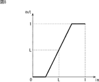
コントラスト調整部132の処理の特性について、図7乃至図9を参照して説明する。画像信号が小さいレベルの領域の場合、ローカルレベルLが小さいため、例えば、図7に示されるような特性となり、コントラスト調整部132においては、黒つぶれ範囲が少なく、白とび範囲が多いコントラスト強調が行われる。しかしながら、この場合は、画像信号が小さい領域のため、白とび範囲の信号は少なく、結果的に黒つぶれも白とびも起きにくいコントラスト調整を行うことができる。
画像信号が中程度のレベルの領域の場合、ローカルレベルLが中程度であるため、例えば、図8に示されるような特性となり、コントラスト調整部132においては、黒つぶれ範囲と白とび範囲が同程度のコントラスト強調が行われる。しかしながら、この場合は、画像信号が中程度の領域のため、黒つぶれ範囲や白とび範囲は少なく、結果的に黒つぶれも白とびも起きにくいコントラスト強調を行うことができる。
画像信号が大きいレベルの領域の場合、ローカルレベルLが大きいため、例えば、図9に示されるような特性となり、コントラスト調整部132においては、黒つぶれ範囲が多く、白とび範囲が少ないコントラスト強調が行われる。しかしながら、この場合は、画像信号が大きい領域のため、黒つぶれ範囲の信号は少なく、結果的に黒つぶれも白とびも起きにくいコントラスト調整を行うことができる。
以上のように、コントラスト調整部132は、ローカルレベル検出部131からのローカルレベルに応じた適応的なコントラスト強調を行う。これにより、白とびや黒つぶれの起きにくいコントラスト調整を行うことができる。
[トーンカーブ調整部の構成]
図10は、図5のトーンカーブ調整部の構成例を示すブロック図である。
図10は、図5のトーンカーブ調整部の構成例を示すブロック図である。
図10の例において、トーンカーブ調整部121は、D(Dynamic)レンジ調整部151および信号分布調整部152を含むように構成されている。
Dレンジ調整部151は、入力画像信号INの画像のダイナミックレンジを調整する。Dレンジ調整部151は、画像のダイナミックレンジが調整された画像信号を、信号分布調整部152に供給する。
図11の例においては、もともとの画像信号(入力画像信号IN)が小さいレベルに偏っている場合に、偏った信号をダイナミックレンジ全体に引き延ばす例が示されている。図12の例においては、もともとの画像信号(入力画像信号IN)が中程度のレベルに偏っている場合に、偏った信号をダイナミックレンジ全体に引き延ばす例が示されている。
このように、Dレンジ調整部151は、画像信号の分布を検出し、ダイナミックレンジが有効に活かせるように信号レベルを調整している。なお、画像信号の分布の検出は画面全体に対して行ってもよいし、特定領域に限定して行ってもよい。
信号分布調整部152は、画像信号の信号分布を調整し、画像を強調する。強調された画像は、適応的コントラスト調整部122に供給される。
図13の例においては、画像の主要被写体の領域を処理対象としている場合の例として、信号分布調整部152により、信号レベルの平均値を持ち上げてより明るくすることで、画像(の主要被写体の領域)を強調する例が示されている。
以上のようにして信号分布調整部152により強調された画像の信号は、適応的コントラスト調整部122に供給される。
[画像処理の例]
次に、図14のフローチャートを参照して、図4の画像処理装置100による画像処理について説明する。
次に、図14のフローチャートを参照して、図4の画像処理装置100による画像処理について説明する。
図示せぬ前段から、主要部用画像処理部111-1および背景部用画像処理部111-2に、入力画像信号INが供給される。
ステップS111において、主要部用画像処理部111-1は、主要部用画像処理を行う。また、ステップS112において、背景部用画像処理部111-2は、背景用画像処理を行う。なお、これらの主要部用画像処理および背景部用画像処理については、各部用画像処理として、図15を参照して詳しく後述される。
ステップS111により、主要被写体の領域に対して、トーンカーブ調整と適応的コントラスト調整とを用いた画像処理が行われ、画像処理後の画像信号が、画像合成部112に供給される。同様に、ステップS112により、主要被写体以外の他の領域に対して、トーンカーブ調整と適応的コントラスト調整とを用いた画像処理が行われ、画像処理後の画像信号が、画像合成部112に供給される。
なお、ステップS111とS112の処理は、並列で行われてもよい。あるいは、外部からの制御などにより、どちらか一方が行われ、どちらか他方においては、入力画像信号INがそのまま画像合成部112に供給されるようにしてもよい。
ステップS113において、画像合成部112は、画像を合成する。すなわち、画像合成部112は、主要部用画像処理部111-1からの主要部用画像と、背景部用画像処理部111-2からの背景部用画像を用いて合成画像を作成する。作成された合成画像の信号は、出力画像信号OUTとして図示せぬ後段に供給される。
[各部用画像処理の例]
次に、図15のフローチャートを参照して、図14のステップS111およびS112の各部用画像処理について説明する。
次に、図15のフローチャートを参照して、図14のステップS111およびS112の各部用画像処理について説明する。
ステップS131において、Dレンジ調整部151は、入力画像信号INの画像のダイナミックレンジを調整する。Dレンジ調整部151は、画像のダイナミックレンジが調整された画像信号を、信号分布調整部152に供給する。
ステップS132において、信号分布調整部152は、画像信号の信号分布を調整し、画像を強調する。例えば、信号レベルの平均値を持ち上げてより明るくすることで、主要被写体領域を強調する調整が行われる。強調された画像は、適応的コントラスト調整部122に供給される。
ステップS133において、ローカルレベル検出部131は、注目画素の周辺領域のレベルであるローカルレベルを検出する。ローカルレベル検出部131は、検出したローカルレベル信号(例えば、局所レベルの平均値)を、コントラスト調整部132に出力する。
ステップS134において、コントラスト調整部132は、トーンカーブの調整が行われた画像信号から、ローカルレベル信号を減算し、その結果を、トーンカーブの調整が行われた画像信号に加算して、出力画像信号OUTを得ることで、コントラストを調整する。
すなわち、減算器141は、トーンカーブの調整が行われた画像信号から、ローカルレベル信号を減算し、その結果を、加算器142に出力する。加算器142は、トーンカーブの調整が行われた画像信号に、減算器141による減算結果を加算し、その結果の出力画像信号OUTを、後段に出力する。
以上により、図7乃至図9を参照して上述したように、検出されたローカルレベルに応じて適応的なコントラスト調整が行われるので、結果的に黒つぶれも白とびも起きにくいコントラスト強調を行うことができる。さらに、その強調が、主要被写体領域が強調された上で行われるので、画像において主要被写体をより際立たせることができる。
[適応的コントラスト調整部の他の例]
図16は、図5の適応的コントラスト調整部の他の構成例を示すブロック図である。
図16は、図5の適応的コントラスト調整部の他の構成例を示すブロック図である。
図16の例において、適応的コントラスト調整部122は、ローカルレベル検出部131、ローカルレベル調整部161、コントラスト調整部162、ゲイン調整係数設定部163、およびゲイン調整部164を含むように構成されている。
図16の適応的コントラスト調整部122は、ローカルレベル検出部131を備える点が、図5の適応的コントラスト調整部122と共通している。
図16の適応的コントラスト調整部122は、コントラスト調整部132がコントラスト調整部162に入れ替わった点が、図5の適応的コントラスト調整部122と異なっている。図16の適応的コントラスト調整部122は、ローカルレベル調整部161、ゲイン調整係数設定部163、およびゲイン調整部164を備える点が、図5の適応的コントラスト調整部122と異なっている。
すなわち、ローカルレベル検出部131からのローカルレベル信号は、ローカルレベル調整部161に供給される。
ローカルレベル調整部161は、ローカルレベル検出部131により求められたローカルレベルを調整する。ローカルレベル調整部161は、調整されたローカルレベル信号を、コントラスト調整部162に供給する。
コントラスト調整部162は、トーンカーブの調整が行われた画像信号から、ローカルレベル信号を減算し、その結果にゲインをかけたものを、トーンカーブの調整が行われた画像信号に加算して、出力画像信号OUTを得るものである。
具体的には、コントラスト調整部162は、減算器141および加算器142を備える点は、図5のコントラスト調整部132と共通している。コントラスト調整部162は、ゲイン調整部164からのゲインを乗算する乗算器171が追加された点が、図5のコントラスト調整部132と異なっている。
すなわち、減算器141は、トーンカーブの調整が行われた画像信号から、ローカルレベル信号を減算し、その結果を、乗算器171に出力する。乗算器171は、減算器141により減算された結果に、ゲイン調整部164からのゲインを乗算する。乗算器171は、ゲインが乗算された結果を、加算器142に出力する。加算器142は、トーンカーブの調整が行われた画像信号に、乗算器171によるゲイン乗算結果を加算し、その結果の出力画像信号OUTを、後段に出力する。
また、図16の例においては、前段からの入力画像信号INは、ローカルレベル検出部131とゲイン調整係数設定部163に供給される。
ゲイン調整係数設定部163は、入力画像信号INに応じて、ゲインを調整する係数を求めて設定し、設定された係数をゲイン調整部164に供給する。
ゲイン調整部164は、ゲイン調整係数設定部163で得られた係数を予め設定されたゲインGに乗算して、ゲインを調整する。ゲイン調整部164により調整されたゲインは、コントラスト調整部162の乗算器171に供給される。
[ローカルレベル調整]
ここで、ローカルレベル調整部161について説明する。図17の例において、実線がローカルレベル調整部161の特性の一例を表している。
ここで、ローカルレベル調整部161について説明する。図17の例において、実線がローカルレベル調整部161の特性の一例を表している。
すなわち、ローカルレベル調整部161は、入力信号のレベル(以下、入力レベルと称する)がbよりも小さいと入力レベルより出力信号のレベル(以下、出力レベルと称する)を小さくする。また、ローカルレベル調整部161は、入力レベルがbより大きいと、入力レベルより出力レベルを大きくする。
このようなローカルレベル調整を行うことにより、画像信号が小さいレベルの領域においては、例えば、上述した図7に示されるローカルレベルLがより小さい方向にシフトした特性となり黒つぶれがより軽減されることになる。
また、画像信号が大きいレベルの領域においては、ローカルレベルがより大きくなるため、上述した図9に示されるローカルレベルLがより大きい方向にシフトした特性となり白とびがより軽減されることになる。
これらの効果は、図17に示される傾きaが大きいほど強くなる。
また、ローカルレベル調整部161の特性は、例えば、図18の例の実線のように表わされる。図18の例においては、図17の例の場合よりbがより小さく設定されている。
このようなローカルレベル調整を行うことにより、ローカルレベルが大きいときにより大きくする効果が強くなるため、黒つぶれ軽減よりも白とび軽減の効果を重視することができる。
さらに、ローカルレベル調整部161の特性は、例えば、図19の実線のように表される。図19の例においては、図17の例の場合よりbがより大きく設定されている。
このようなローカルレベル調整を行うことにより、ローカルレベルが小さいときにより小さくする効果が強くなるため、白とび軽減よりも黒つぶれ軽減の効果を重視することができる。以上のように、輝度分布の偏りに応じた時性で、画像のローカルレベル(例えば、局所領域の平均値)が調整される。
[ゲイン調整係数設定]
次に、ゲイン調整係数設定部163について説明する。図20の例において、実線は、ゲイン調整係数設定部の特性の一例を表している。
次に、ゲイン調整係数設定部163について説明する。図20の例において、実線は、ゲイン調整係数設定部の特性の一例を表している。
ゲイン調整係数設定部163の特性は、信号分布調整部152の特性を考慮して決定される。上述したように、信号分布調整の結果は、図13の傾きが小さい(すなわち、信号レベルが大きい)部分ほどコントラストが低下する。したがって、図13の特性の微分の逆数に比例する特性をゲイン調整係数設定部163に持たせるようにすることで、トータルでのコントラスト強調特性が一定になる。その結果、ゲインを大きくしたときの黒つぶれを軽減することができる。
そのような特性の一例が図20に示される特性である。また、図21に示される特性においては、図20に示される特性よりも信号レベルの低い部分ほどコントラスト強調効果が強くなる。
[各部用画像処理の例]
次に、図22のフローチャートを参照して、図14のステップS111およびS112の各部用画像処理について説明する。
次に、図22のフローチャートを参照して、図14のステップS111およびS112の各部用画像処理について説明する。
ステップS161において、Dレンジ調整部151は、入力画像信号INの画像のダイナミックレンジを調整する。Dレンジ調整部151は、画像のダイナミックレンジが調整された画像信号を、信号分布調整部152に供給する。
ステップS162において、信号分布調整部152は、画像信号の信号分布を調整し、画像を強調する。例えば、信号レベルの平均値を持ち上げてより明るくすることで、主要被写体領域を強調する調整が行われる。強調された画像は、適応的コントラスト調整部122に供給される。
ステップS163において、ローカルレベル検出部131は、注目画素の周辺領域のレベルであるローカルレベルを検出する。ローカルレベル検出部131は、検出したローカルレベル信号を、ローカルレベル調整部161に出力する。
ステップS164において、ローカルレベル調整部161は、ローカルレベル検出部131により求められたローカルレベルを調整する。ローカルレベル調整部161は、調整されたローカルレベル信号を、コントラスト調整部162に供給する。
ステップS165において、ゲイン調整係数設定部163は、信号分布調整部152からの入力画像信号INに応じて、ゲインを調整する係数を求めて設定し、設定された係数をゲイン調整部164に供給する。
ステップS166において、ゲイン調整部164は、ゲイン調整係数設定部163で得られた係数を予め設定されたゲインGに乗算して、ゲインを調整する。ゲイン調整部164により調整されたゲインは、コントラスト調整部162の乗算器171に供給される。
ステップS167において、コントラスト調整部162は、トーンカーブの調整が行われた画像信号から、ローカルレベル信号を減算する。そして、コントラスト調整部162は、その結果にゲインをかけたものを、トーンカーブの調整が行われた画像信号に加算して、出力画像信号OUTを得ることで、コントラストを調整(強調)する。
すなわち、減算器141は、トーンカーブの調整が行われた画像信号から、ローカルレベル信号を減算し、その結果を、乗算器171に出力する。乗算器171は、減算器141により減算された結果に、ゲイン調整部164からのゲインを乗算する。乗算器171は、ゲインが乗算された結果を、加算器142に出力する。加算器142は、トーンカーブの調整が行われた画像信号に、乗算器171によるゲイン乗算結果を加算し、その結果の出力画像信号OUTを、後段に出力する。
以上のように、検出されたローカルレベルに応じて、より適応的なコントラスト調整が行われるので、結果的に黒つぶれも白とびも起きにくいコントラスト強調を行うことができる。さらに、その強調が、主要被写体領域が強調された上で行われるので、画像において主要被写体をより際立たせることができる。
<2.第2の実施の形態(画像処理装置)>
[画像処理装置の構成例]
図23は、本技術を適用した画像処理装置の他の実施の形態を示すブロック図である。
[画像処理装置の構成例]
図23は、本技術を適用した画像処理装置の他の実施の形態を示すブロック図である。
図23の画像処理装置200は、主要部用画像処理部111-1、背景部用画像処理部111-2、および画像合成部112を備える点が、図4の画像処理装置100と共通している。図23の画像処理装置200は、主要被写体領域設定部211が追加された点が、図4の画像処理装置100と異なっている。
主要被写体領域設定部211は、画像の中の主要被写体を検出し、検出された主要被写体情報から想定される主要被写体領域を設定する。
具体的には、主要被写体領域設定部211は、画像の中の主要被写体を検出する。主要被写体の検出には様々な方法があるが、ここでは、例えば、主要被写体が人物であるとして顔検出を利用する場合を例とする。この場合、顔検出により顔領域情報が得られ、主要被写体情報とされる。なお、ユーザが主要被写体領域を設定することも可能である。
そして、主要被写体領域設定部211は、主要被写体情報から想定される主要被写体領域を設定する。主要被写体検出が顔検出の場合、主要被写体領域としては、顔領域から想定される人物領域を設定する。
例えば、図24の例においては、顔領域aに拡張領域bを加えた領域のサイズに対して、付加値cを加えたものを径とする楕円(長径a+b+2c、短径a+2c)を主要被写体領域とする例が示されている。これは、被写体が比較的小さく写っている場合であり、拡張領域bは胴体付近まで含まれるように設定されている。
また、例えば、図25の例においては、顔領域aに拡張領域bを加えた領域のサイズに対して、付加値cを加えたものを径とする楕円(長径a+b+2c、短径a+2c)を主要被写体領域とする例が示されている。これは、被写体が比較的大きく写っている場合であり、拡張領域bは首付近まで含まれるように設定されている。
なお、被写体が中程度の大きさで写っている場合には、拡張領域bは胸付近まで含まれるようにするのが望ましい。
このように、主要被写体領域設定部211においては、顔サイズが小さいほど顔領域から胴体方向への拡張量が大きく設定される。図26の例においては、このような特性が実線で示されている。
また、付加値cは、顔サイズによらず、ほぼ一定とするのがよい。
なお、主要被写体が複数ある場合、それらの領域を合成したものを主要被写体領域としてもよいし、いずれかを選択して主要被写体領域としてもよい。また、主要被写体が検出されない場合は、画面中央付近に主要被写体領域を設定してもよい。さらに、主要被写体が検出されても、画面の端に偏っている場合などは、画面中央方向に領域を拡張するようにしてもよい。また、検出された主要被写体を拡張することなしに、主要被写体領域としてもよい(すなわち、検出されたままの領域を主要被写体領域として使用してもよい)。
また、この主要被写体領域に対しては、ローパスフィルタなどにより境界ぼかしを行ってもよい。
[画像処理の例]
次に、図27のフローチャートを参照して、図23の画像処理装置200による画像処理について説明する。
次に、図27のフローチャートを参照して、図23の画像処理装置200による画像処理について説明する。
図示せぬ前段から、主要被写体領域設定部211、主要部用画像処理部111-1および背景部用画像処理部111-2に、入力画像信号INが供給される。
ステップS211において、主要被写体領域設定部211は、入力画像信号INの画像の主要被写体を検出する。例えば、顔検出により顔領域情報が得られ、主要被写体情報とされる。
そして、ステップS212において、主要被写体領域設定部211は、主要被写体情報から想定される主要被写体領域を設定する。例えば、主要被写体検出が顔検出の場合、主要被写体領域としては、顔領域から想定される人物領域を設定する。
ステップS213において、主要部用画像処理部111-1は、主要部用画像処理を行う。また、ステップS214において、背景部用画像処理部111-2は、背景用画像処理を行う。なお、これらの主要部用画像処理および背景部用画像処理については、図15を参照して上述された各部用画像処理と基本的に同様な処理を行うため、その説明は繰り返しになるので省略される。
ステップS213により、主要被写体の領域に対して、トーンカーブ調整と適応的コントラスト調整とを用いた画像処理が行われ、画像処理後の画像信号が、画像合成部112に供給される。同様に、ステップS214により、主要被写体以外の他の領域に対して、トーンカーブ調整と適応的コントラスト調整とを用いた画像処理が行われ、画像処理後の画像信号が、画像合成部112に供給される。
なお、図14の例と同様に、ステップS213とS214の処理は、並列で行われてもよいし、外部からの制御などにより、どちらか一方が行われ、どちらか他方においては、入力画像信号INがそのまま画像合成部112に供給されるようにしてもよい。
ステップS215において、画像合成部112は、画像を合成する。すなわち、画像合成部112は、主要部用画像処理部111-1からの主要部用画像を用い、背景部用画像処理部111-2からの背景部用画像を用いて合成画像を作成する。作成された合成画像の信号は、出力画像信号OUTとして図示せぬ後段に供給される。
<3.第3の実施の形態(変形例)>
[主要部用画像処理部の構成]
図28は、主要部用画像処理部111-1の構成のパターンを示す図である。
[主要部用画像処理部の構成]
図28は、主要部用画像処理部111-1の構成のパターンを示す図である。
主要部用画像処理部111-1は、画像を明るくし、コントラストを強調することで、際立った印象を与える画像を作成するものである。
主要部用画像処理部111-1は、構成1として、図5および図7を参照して上述したように、Dレンジ調整部151、信号分布調整部152、および適応的コントラスト調整部122を含むように構成される。
この場合、Dレンジ調整部151は、例えば、画像の主要被写体領域について画像信号分布を検出して、図11および図12を参照して上述したようにダイナミックレンジを調整する。信号分布調整部152は、例えば、上述した図13のような特性を用いて信号レベルの平均値を持ち上げて明るくすることで、画像(の主要被写体の領域)を強調する。
適応的コントラスト調整部122は、例えば、図7乃至図9を参照して上述したように、適応的なコントラスト強調を行うことで白とび黒つぶれの少ないコントラスト強調を行う。
なお、構成2として示されるように、主要部用画像処理部111-1において、Dレンジ調整部151は、必須の構成要件ではない。
すなわち、主要部用画像処理部111-1は、構成2として、信号分布調整部152、および適応的コントラスト調整部122を含むように構成される。
ここで、Dレンジ調整が有効であるのは、もともとの画像の輝度分布が狭い場合である。例えば、靄がかかった画像のとき、Dレンジ調整をすることで、靄が晴れたような画像になる。すなわち、輝度分布範囲が狭い画像ほど構成1にすると、しゃっきりした画像が得られる。
したがって、主要部用画像処理部111-1の構成は、通常は構成2であり、画像の輝度分布範囲が狭い場合に構成1に自動で切り替わる。
なお、適応的コントラスト調整部122の適応的コントラスト調整において、図7乃至図9に示される特性は、ローカルレベル検出部131となるローパスフィルタの出力レベルLによって自動で切り替えられる。
また、適応的コントラスト調整部122のローカルレベル調整において、図17乃至図19に示される特性のうち、通常は、図17の特性である。また、輝度分布が高輝度に偏っているときは、白とび軽減を重視して図18の特性に切り替わり、輝度分布が低輝度に偏っているときは、黒ベタ軽減を重視して図19の特性に切り替わる。
[背景部用画像処理部の構成]
図29は、背景部用画像処理部111-2の構成のパターンを示す図である。
図29は、背景部用画像処理部111-2の構成のパターンを示す図である。
背景部用画像処理部111-2は、画像を暗くしながらも、コントラストを強調することで、主要部がより際立った印象を与える画像を作成するものである。なお、背景を単に暗くするだけでも主要部を際立たせる効果はあるが、さらにコントラストを強調することで暗い中にも明るい部分ができるだめ、明暗法による絵画表現に似た効果が得られる。
背景部用画像処理部111-2は、構成1として、図5および図7を参照して上述したように、Dレンジ調整部151、信号分布調整部152、および適応的コントラスト調整部122を含むように構成される。なお、構成は、図28を参照して上述した主要部用画像処理部111-1と同様であるが、それらの特性(パラメータ特性)が異なる。
すなわち、この場合、Dレンジ調整部151は、例えば、画像の主要被写体領域または画像全体について画像信号分布を検出して、図11および図12を参照して上述したようにダイナミックレンジを調整する。信号分布調整部152は、例えば、図30のような特性を用いて信号レベルを低下させて暗くする。
適応的コントラスト調整部122は、例えば、上述したように、適応的なコントラスト強調を行うことで白とび黒つぶれの少ないコントラスト強調を行う。
なお、図28の構成2に対応する構成2-1として示されるように、背景部用画像処理部111-2において、Dレンジ調整部151は、必須の構成要件ではない。すなわち、構成2-1の場合、Dレンジ調整部151は、通常働かせず、信号をスルーさせる。
また、構成2-1のバリエーションである構成2-2として示されるように、背景部用画像処理部111-2において、Dレンジ調整部151の他に、適応的コントラスト調整部122も働かせなくてもよい。換言すると、主要被写体以外の他の領域に対してのコントラスト強調を禁止するようにしてもよい。すなわち、この場合、信号分布調整部152は、例えば、図31のような特性を用いて信号レベルを低下させて暗くするともに、もともと明るい部分はあまり暗くならないようにすることでコントラストを強調することができるからである。
さらに、信号分布調整部152の特性を、例えば、図32のように、1次関数の切片をプラス方向へ変化させることで、非常に明るくなるように設定すると、背景を暗くするのとは異なり、背景を明るく飛ばすことによる主要被写体強調効果を得ることができる。
ここで、主要部用画像処理部111-1と同様に、背景部用画像処理部111-2の構成も、通常は構成2-1(または構成2-2)であり、画像の輝度分布範囲が狭い場合に構成1に自動で切り替わる。
なお、信号分布調整部152の信号分布調整において、図30または図31と、図32の特性は、背景があるレベルより暗い場合、図30または図31に切り替わり、背景があるレベルより明るい場合、図32に切り替わる。
また、適応的コントラスト調整部122のゲイン調整係数設定において、図20と図21に示される特性は、低輝度成分が多いと場合、図20に切り替えられ、低輝度成分が少ない場合、図21に切り替えられる。
以上、画像を強調する画像処理は、輝度信号に適用されるが、その結果の輝度変化に相当するゲインを色信号にかけることで、輝度信号に適した色信号を得ることができる。すなわち、輝度信号がYinからYoutに変化したとすると、色信号にYout/Yinのゲインをかけることにより、輝度信号に適した色信号を得ることができる。なお、その際、輝度信号の背景を明るくした場合、色差信号については背景部分のみの色を消すという処理も行うようにしてもよい。
以上のように、主要被写体領域を明るくしつつ、コントラスト強調を行うことにより、主要被写体を際立たせることができる。また、主要被写体領域以外の背景領域を暗くしつつ、コントラスト強調をすることにより、主要被写体をより際立たせることができる。
さらに、顔の大きさに適した主要被写体領域設定にり適切な主要被写体強調が可能である。
なお、上記説明において、画像に応じて自動で切り替わると説明したものは、ユーザ操作により選択可能に構成することもできる。
また、本技術は、画像処理装置のみに限らず、撮像装置、サーバなどにも適用される。画像処理装置、撮像装置、またはサーバにおいては、例えば、以下のような撮影モードを有しており、撮影モードに応じて、上述した主要部用または背景部用画像処理部を構成する各処理部の特性を設定することが可能である。
[撮影モード]
低コントラストモードは、曇天や霞がかかったような画像の場合に用いられるモードであり、このモードが選択されると、Dレンジ調整部151の処理が行われる。
低コントラストモードは、曇天や霞がかかったような画像の場合に用いられるモードであり、このモードが選択されると、Dレンジ調整部151の処理が行われる。
主題部露光アンダーモードは、背景が明るいため、主題部(主要部)が通常より暗くなる画像の場合に選択されるモードである。このモードが選択されると、図33に示される特性のように、主要部用画像処理部111-1の信号分布調整部152において明るくする効果が強くされる。また、図19を参照して上述したように、適応的コントラスト調整部122のローカルレベル調整において、黒つぶれ軽減重視の設定とされる。
主題部露光オーバーモードは、背景が暗いため主題部が通常より明るくなる画像の場合に選択される。このモードが選択されると、図34に示される特性のように、主要部用画像処理部111-1の信号分布調整部152において明るくする効果が弱くされる。また、図18を参照して上述したように、適応的コントラスト調整部122のローカルレベル調整において、白とび軽減重視の設定とされる。
通常モードが背景を暗くするのに対して、背景とばし(背景白とび)モードは、背景を白くとばしたい画像の場合に選択される。このモードが選択されると、図32に示される特性のように、背景部用画像処理部111-2の信号分布調整部152において非常に明るくする特性とする。なおこのとき、背景部の色信号にかけるゲインを小さくして色消しが行われる。
以上の4つの撮影モードは、ユーザがモード選択可能であり、また、画像処理などで自動モード設定も可能である。
なお、背景とばしモードの場合も、図30または図31の特性と、図32の特性との違いは、背景を暗くしたいか明るくしたいかの違いである。したがって、背景があるレベルより暗いときは、図30または図31の特性、背景があるレベルより明るいときは、図32の特性とすることが可能であるので、自動設定可能である。
なお、上述した図4および図23の画像処理装置においては、主要部用画像処理部111-1および背景部用画像処理部111-2と画像処理部を2つに分ける例が示されているが、構成はそれに限らない。例えば、画像処理部を分けずに1つの画像処理部において処理を切り替えて、主要部用画像と背景部用画像とを処理するようにしてもよい。
上述した一連の処理は、ハードウエアにより実行することもできるし、ソフトウエアにより実行することもできる。一連の処理をソフトウエアにより実行する場合には、そのソフトウエアを構成するプログラムが、コンピュータにインストールされる。ここで、コンピュータには、専用のハードウエアに組み込まれているコンピュータや、各種のプログラムをインストールすることで、各種の機能を実行することが可能な、例えば汎用のパーソナルコンピュータなどが含まれる。
<4.第4の実施の形態(コンピュータ)>
[コンピュータの構成例]
図35は、上述した一連の処理をプログラムにより実行するコンピュータのハードウエアの構成例を示している。
[コンピュータの構成例]
図35は、上述した一連の処理をプログラムにより実行するコンピュータのハードウエアの構成例を示している。
コンピュータ800において、CPU(Central Processing Unit)801,ROM(Read Only Memory)802,RAM(Random Access Memory)803は、バス804により相互に接続されている。
バス804には、さらに、入出力インタフェース805が接続されている。入出力インタフェース805には、入力部806、出力部807、記憶部808、通信部809、及びドライブ810が接続されている。
入力部806は、キーボード、マウス、マイクロホンなどよりなる。出力部807は、ディスプレイ、スピーカなどよりなる。記憶部808は、ハードディスクや不揮発性のメモリなどよりなる。通信部809は、ネットワークインタフェースなどよりなる。ドライブ810は、磁気ディスク、光ディスク、光磁気ディスク、又は半導体メモリなどのリムーバブル記録媒体811を駆動する。
以上のように構成されるコンピュータでは、CPU801が、例えば、記憶部808に記憶されているプログラムを、入出力インタフェース805及びバス804を介して、RAM803にロードして実行することにより、上述した一連の処理が行われる。
コンピュータ(CPU801)が実行するプログラムは、例えば、パッケージメディア等としてのリムーバブル記録媒体811に記録して提供することができる。また、プログラムは、ローカルエリアネットワーク、インターネット、デジタル衛星放送といった、有線または無線の伝送媒体を介して提供することができる。
コンピュータでは、プログラムは、リムーバブル記録媒体811をドライブ810に装着することにより、入出力インタフェース805を介して、記憶部808にインストールすることができる。また、プログラムは、有線または無線の伝送媒体を介して、通信部809で受信し、記憶部808にインストールすることができる。その他、プログラムは、ROM802や記憶部808に、あらかじめインストールしておくことができる。
なお、コンピュータが実行するプログラムは、本明細書で説明する順序に沿って時系列に処理が行われるプログラムであっても良いし、並列に、あるいは呼び出しが行われたとき等の必要なタイミングで処理が行われるプログラムであっても良い。
なお、本明細書において、上述した一連の処理を記述するステップは、記載された順序に沿って時系列的に行われる処理はもちろん、必ずしも時系列的に処理されなくとも、並列的あるいは個別に実行される処理をも含むものである。
例えば、本技術は、1つの機能を、ネットワークを介して複数の装置で分担、共同して処理するクラウドコンピューティングの構成をとることができる。
また、本開示における実施の形態は、上述した実施の形態に限定されるものではなく、本開示の要旨を逸脱しない範囲において種々の変更が可能である。
また、上述のフローチャートで説明した各ステップは、1つの装置で実行する他、複数の装置で分担して実行することができる。
さらに、1つのステップに複数の処理が含まれる場合には、その1つのステップに含まれる複数の処理は、1つの装置で実行する他、複数の装置で分担して実行することができる。
また、以上において、1つの装置(または処理部)として説明した構成を分割し、複数の装置(または処理部)として構成するようにしてもよい。逆に、以上において複数の装置(または処理部)として説明した構成をまとめて1つの装置(または処理部)として構成されるようにしてもよい。また、各装置(または各処理部)の構成に上述した以外の構成を付加するようにしてももちろんよい。さらに、システム全体としての構成や動作が実質的に同じであれば、ある装置(または処理部)の構成の一部を他の装置(または他の処理部)の構成に含めるようにしてもよい。つまり、本技術は、上述した実施の形態に限定されるものではなく、本技術の要旨を逸脱しない範囲において種々の変更が可能である。
以上、添付図面を参照しながら本開示の好適な実施形態について詳細に説明したが、開示はかかる例に限定されない。本開示の属する技術の分野における通常の知識を有するであれば、請求の範囲に記載された技術的思想の範疇内において、各種の変更例また修正例に想到し得ることは明らかであり、これらについても、当然に本開示の技術的範囲に属するものと了解される。
なお、本技術は以下のような構成も取ることができる。
(1) 画像の主要被写体領域および前記主要被写体領域以外の領域である他の領域の少なくとも一方の領域にトーンカーブ調整を行うトーンカーブ調整部と、
前記トーンカーブ調整部によりトーンカーブ調整が行われた領域に対して、コントラスト強調を行うコントラスト調整部と
を備える画像処理装置。
(2) 前記トーンカーブ調整部は、前記主要被写体領域を明るくするトーンカーブ調整を行う
前記(1)に記載の画像処理装置。
(3) 前記トーンカーブ調整部は、ダイナミックレンジの調整後、前記主要被写体領域を明るくするトーンカーブ調整を行う
前記(2)に記載の画像処理装置。
(4) 前記トーンカーブ調整部は、前記他の領域の明るさに応じて、前記主要被写体領域を明るくするトーンカーブ調整を行う
前記(2)に記載の画像処理装置。
(5) 前記トーンカーブ調整部は、ユーザの操作に応じて、前記主要被写体領域を明るくするトーンカーブ調整を行う
前記(2)に記載の画像処理装置。
(6) 前記トーンカーブ調整部は、前記他の領域を暗くするトーンカーブ調整を行う
前記(1)乃至(5)のいずれかに記載の画像処理装置。
(7) 前記トーンカーブ調整部は、ダイナミックレンジの調整後、前記他の領域を暗くするトーンカーブ調整を行う
前記(6)に記載の画像処理装置。
(8) 前記トーンカーブ調整部は、前記他の領域の明るさに応じて、前記他の領域を暗く、または明るくするトーンカーブ調整を行う
前記(6)に記載の画像処理装置。
(9) 前記トーンカーブ調整部は、ユーザの操作に応じて、前記他の領域を暗く、または明るくするトーンカーブ調整を行う
前記(6)に記載の画像処理装置。
(10) 前記トーンカーブ調整部は、前記他の領域の明るい部分以外の部分を暗くするトーンカーブ調整を行う
前記(6)に記載の画像処理装置。
(11) 前記コントラスト調整部は、前記トーンカーブ調整部によりトーンカーブ調整が行われた領域に前記他の領域が含まれる場合、前記他の領域に対してのコントラスト強調を禁止する
前記(10)に記載の画像処理装置。
(12) 前記トーンカーブ調整部は、前記主要被写体領域を明るくし、前記他の領域を暗くするトーンカーブ調整を行う
前記(1)乃至(11)のいずれかに記載の画像処理装置。
(13) 前記コントラスト調整部は、前記画像の局所領域の平均値によって領域毎にコントラスト強調特性を可変としたコントラスト強調を行う
前記(1)乃至(12)のいずれかに記載の画像処理装置。
(14) 前記コントラスト調整部は、
前記画像の局所領域の平均値を調整するローカルレベル調整部を備え、
前記ローカルレベル調整部により調整された画像の局所領域の平均値によって領域毎にコントラスト強調特性を可変としたコントラスト強調を行う
前記(13)に記載の画像処理装置。
(15) 前記ローカルレベル調整部は、輝度分布の偏りに応じた特性で、前記画像の局所領域の平均値を調整する
前記(14)に記載の画像処理装置。
(16) 前記ローカルレベル調整部は、ユーザの操作に応じて、前記画像の局所領域の平均値を調整する
前記(14)に記載の画像処理装置。
(17) 前記主要被写体領域は、顔領域と前記顔領域から胴体方向に拡張が行われた領域とを含む
前記(1)乃至(16)のいずれかに記載の画像処理装置。
(18) 前記拡張の量は、前記顔領域のサイズ大きくなるほど小さくなる
前記(17)に記載の画像処理装置。
(19) 画像処理装置が、
画像の主要被写体領域および前記主要被写体領域以外の領域である他の領域の少なくとも一方の領域にトーンカーブ調整を行い、
前記トーンカーブ調整が行われた領域に対して、コントラスト強調を行う
画像処理方法。
(20) 画像の主要被写体領域および前記主要被写体領域以外の領域である他の領域の少なくとも一方の領域にトーンカーブ調整を行うトーンカーブ調整部と、
前記トーンカーブ調整部によりトーンカーブ調整が行われた領域に対して、コントラスト強調を行うコントラスト調整部と
してコンピュータを機能させるプログラム。
100 画像処理装置, 111 各部用画像処理部, 111-1 主要部用画像処理部, 111-2 背景部用画像処理部, 112 画像合成部, 121 トーンカーブ調整部,122 適応的コントラスト調整部, 131 ローカルレベル検出部, 132 コントラスト調整部, 141 減算器, 142 加算器, 151 Dレンジ調整部, 152 信号分布部, 161 ローカルレベル調整部, 162 コントラスト調整部, 163 ゲイン調整係数設定部, 164 ゲイン調整部, 200 主要被写体領域設定部
Claims (20)
- 画像の主要被写体領域および前記主要被写体領域以外の領域である他の領域の少なくとも一方の領域にトーンカーブ調整を行うトーンカーブ調整部と、
前記トーンカーブ調整部によりトーンカーブ調整が行われた領域に対して、コントラスト強調を行うコントラスト調整部と
を備える画像処理装置。 - 前記トーンカーブ調整部は、前記主要被写体領域を明るくするトーンカーブ調整を行う
請求項1に記載の画像処理装置。 - 前記トーンカーブ調整部は、ダイナミックレンジの調整後、前記主要被写体領域を明るくするトーンカーブ調整を行う
請求項2に記載の画像処理装置。 - 前記トーンカーブ調整部は、前記他の領域の明るさに応じて、前記主要被写体領域を明るくするトーンカーブ調整を行う
請求項2に記載の画像処理装置。 - 前記トーンカーブ調整部は、ユーザの操作に応じて、前記主要被写体領域を明るくするトーンカーブ調整を行う
請求項2に記載の画像処理装置。 - 前記トーンカーブ調整部は、前記他の領域を暗くするトーンカーブ調整を行う
請求項1に記載の画像処理装置。 - 前記トーンカーブ調整部は、ダイナミックレンジの調整後、前記他の領域を暗くするトーンカーブ調整を行う
請求項6に記載の画像処理装置。 - 前記トーンカーブ調整部は、前記他の領域の明るさに応じて、前記他の領域を暗く、または明るくするトーンカーブ調整を行う
請求項6に記載の画像処理装置。 - 前記トーンカーブ調整部は、ユーザの操作に応じて、前記他の領域を暗く、または明るくするトーンカーブ調整を行う
請求項6に記載の画像処理装置。 - 前記トーンカーブ調整部は、前記他の領域の明るい部分以外の部分を暗くするトーンカーブ調整を行う
請求項6に記載の画像処理装置。 - 前記コントラスト調整部は、前記トーンカーブ調整部によりトーンカーブ調整が行われた領域に前記他の領域が含まれる場合、前記他の領域に対してのコントラスト強調を禁止する
請求項10に記載の画像処理装置。 - 前記トーンカーブ調整部は、前記主要被写体領域を明るくし、前記他の領域を暗くするトーンカーブ調整を行う
請求項1に記載の画像処理装置。 - 前記コントラスト調整部は、前記画像の局所領域の平均値によって領域毎にコントラスト強調特性を可変としたコントラスト強調を行う
請求項1に記載の画像処理装置。 - 前記コントラスト調整部は、
前記画像の局所領域の平均値を調整するローカルレベル調整部を備え、
前記ローカルレベル調整部により調整された画像の局所領域の平均値によって領域毎にコントラスト強調特性を可変としたコントラスト強調を行う
請求項13に記載の画像処理装置。 - 前記ローカルレベル調整部は、輝度分布の偏りに応じた特性で、前記画像の局所領域の平均値を調整する
請求項14に記載の画像処理装置。 - 前記ローカルレベル調整部は、ユーザの操作に応じて、前記画像の局所領域の平均値を調整する
請求項14に記載の画像処理装置。 - 前記主要被写体領域は、顔領域と前記顔領域から胴体方向に拡張が行われた領域とを含む
請求項1に記載の画像処理装置。 - 前記拡張の量は、前記顔領域のサイズ大きくなるほど小さくなる
請求項17に記載の画像処理装置。 - 画像処理装置が、
画像の主要被写体領域および前記主要被写体領域以外の領域である他の領域の少なくとも一方の領域にトーンカーブ調整を行い、
前記トーンカーブ調整が行われた領域に対して、コントラスト強調を行う
画像処理方法。 - 画像の主要被写体領域および前記主要被写体領域以外の領域である他の領域の少なくとも一方の領域にトーンカーブ調整を行うトーンカーブ調整部と、
前記トーンカーブ調整部によりトーンカーブ調整が行われた領域に対して、コントラスト強調を行うコントラスト調整部と
してコンピュータを機能させるプログラム。
Priority Applications (1)
| Application Number | Priority Date | Filing Date | Title |
|---|---|---|---|
| US14/893,917 US9754362B2 (en) | 2013-05-31 | 2014-05-19 | Image processing apparatus, image processing method, and program |
Applications Claiming Priority (2)
| Application Number | Priority Date | Filing Date | Title |
|---|---|---|---|
| JP2013-115723 | 2013-05-31 | ||
| JP2013115723 | 2013-05-31 |
Publications (1)
| Publication Number | Publication Date |
|---|---|
| WO2014192577A1 true WO2014192577A1 (ja) | 2014-12-04 |
Family
ID=51988612
Family Applications (1)
| Application Number | Title | Priority Date | Filing Date |
|---|---|---|---|
| PCT/JP2014/063210 WO2014192577A1 (ja) | 2013-05-31 | 2014-05-19 | 画像処理装置、画像処理方法、およびプログラム |
Country Status (2)
| Country | Link |
|---|---|
| US (1) | US9754362B2 (ja) |
| WO (1) | WO2014192577A1 (ja) |
Cited By (1)
| Publication number | Priority date | Publication date | Assignee | Title |
|---|---|---|---|---|
| WO2018047557A1 (ja) * | 2016-09-06 | 2018-03-15 | ソニー株式会社 | 画像処理装置、および画像処理方法、並びにプログラム |
Families Citing this family (2)
| Publication number | Priority date | Publication date | Assignee | Title |
|---|---|---|---|---|
| US11430093B2 (en) | 2019-10-01 | 2022-08-30 | Microsoft Technology Licensing, Llc | Face-based tone curve adjustment |
| WO2021075134A1 (ja) * | 2019-10-16 | 2021-04-22 | パナソニックIpマネジメント株式会社 | 画像処理方法、画像処理システムおよび画像処理装置 |
Citations (8)
| Publication number | Priority date | Publication date | Assignee | Title |
|---|---|---|---|---|
| JP2002262094A (ja) * | 2001-02-27 | 2002-09-13 | Konica Corp | 画像処理方法及び画像処理装置 |
| JP2004221645A (ja) * | 2003-01-09 | 2004-08-05 | Sony Corp | 画像処理装置および方法、記録媒体、並びにプログラム |
| JP2007234036A (ja) * | 2007-04-04 | 2007-09-13 | Matsushita Electric Ind Co Ltd | 画像処理装置および画像処理方法および画像処理に用いられるプロセッサ |
| JP2009206585A (ja) * | 2008-02-26 | 2009-09-10 | Nikon Corp | 画像処理装置、画像処理プログラムおよびデジタルカメラ |
| JP2009290661A (ja) * | 2008-05-30 | 2009-12-10 | Seiko Epson Corp | 画像処理装置、画像処理方法、画像処理プログラムおよび印刷装置 |
| JP2010233236A (ja) * | 2004-03-08 | 2010-10-14 | Seiko Epson Corp | 主要被写体に応じた画質の向上 |
| JP2011024247A (ja) * | 2009-06-15 | 2011-02-03 | Konica Minolta Opto Inc | 撮像装置 |
| JP2011259053A (ja) * | 2010-06-07 | 2011-12-22 | Olympus Imaging Corp | 画像処理装置および画像処理方法 |
Family Cites Families (7)
| Publication number | Priority date | Publication date | Assignee | Title |
|---|---|---|---|---|
| TW499812B (en) * | 2001-02-01 | 2002-08-21 | Ind Tech Res Inst | Method to determine the semi-S curve tone process of digital image |
| US7068841B2 (en) * | 2001-06-29 | 2006-06-27 | Hewlett-Packard Development Company, L.P. | Automatic digital image enhancement |
| JP4240023B2 (ja) * | 2005-08-31 | 2009-03-18 | ソニー株式会社 | 撮像装置、撮像方法および撮像プログラム、ならびに、画像処理装置、画像処理方法および画像処理プログラム |
| US8355595B2 (en) * | 2007-05-15 | 2013-01-15 | Xerox Corporation | Contrast enhancement methods and apparatuses |
| JP4600448B2 (ja) * | 2007-08-31 | 2010-12-15 | カシオ計算機株式会社 | 階調補正装置、階調補正方法、及び、プログラム |
| US8483508B2 (en) * | 2008-08-19 | 2013-07-09 | Kabushiki Kaisha Toshiba | Digital image tone adjustment |
| JP2012083848A (ja) | 2010-10-07 | 2012-04-26 | Olympus Corp | 画像処理装置、画像処理方法、撮像装置、および画像処理プログラム |
-
2014
- 2014-05-19 US US14/893,917 patent/US9754362B2/en active Active
- 2014-05-19 WO PCT/JP2014/063210 patent/WO2014192577A1/ja active Application Filing
Patent Citations (8)
| Publication number | Priority date | Publication date | Assignee | Title |
|---|---|---|---|---|
| JP2002262094A (ja) * | 2001-02-27 | 2002-09-13 | Konica Corp | 画像処理方法及び画像処理装置 |
| JP2004221645A (ja) * | 2003-01-09 | 2004-08-05 | Sony Corp | 画像処理装置および方法、記録媒体、並びにプログラム |
| JP2010233236A (ja) * | 2004-03-08 | 2010-10-14 | Seiko Epson Corp | 主要被写体に応じた画質の向上 |
| JP2007234036A (ja) * | 2007-04-04 | 2007-09-13 | Matsushita Electric Ind Co Ltd | 画像処理装置および画像処理方法および画像処理に用いられるプロセッサ |
| JP2009206585A (ja) * | 2008-02-26 | 2009-09-10 | Nikon Corp | 画像処理装置、画像処理プログラムおよびデジタルカメラ |
| JP2009290661A (ja) * | 2008-05-30 | 2009-12-10 | Seiko Epson Corp | 画像処理装置、画像処理方法、画像処理プログラムおよび印刷装置 |
| JP2011024247A (ja) * | 2009-06-15 | 2011-02-03 | Konica Minolta Opto Inc | 撮像装置 |
| JP2011259053A (ja) * | 2010-06-07 | 2011-12-22 | Olympus Imaging Corp | 画像処理装置および画像処理方法 |
Cited By (5)
| Publication number | Priority date | Publication date | Assignee | Title |
|---|---|---|---|---|
| WO2018047557A1 (ja) * | 2016-09-06 | 2018-03-15 | ソニー株式会社 | 画像処理装置、および画像処理方法、並びにプログラム |
| CN109661806A (zh) * | 2016-09-06 | 2019-04-19 | 索尼公司 | 图像处理装置、图像处理方法和程序 |
| JPWO2018047557A1 (ja) * | 2016-09-06 | 2019-06-24 | ソニー株式会社 | 画像処理装置、および画像処理方法、並びにプログラム |
| US10832636B2 (en) | 2016-09-06 | 2020-11-10 | Sony Corporation | Image processing apparatus, image processing method, and program |
| CN109661806B (zh) * | 2016-09-06 | 2022-03-08 | 索尼公司 | 图像处理装置、图像处理方法和程序 |
Also Published As
| Publication number | Publication date |
|---|---|
| US20160110854A1 (en) | 2016-04-21 |
| US9754362B2 (en) | 2017-09-05 |
Similar Documents
| Publication | Publication Date | Title |
|---|---|---|
| JP5136664B2 (ja) | 画像処理装置、及びプログラム | |
| JP5157753B2 (ja) | 画像処理装置、画像処理方法、画像処理プログラム | |
| US8472713B2 (en) | Image processor, image processing method, and computer-readable medium | |
| JP3430998B2 (ja) | 画像表示装置および画像表示方法 | |
| EP2076013B1 (en) | Method of high dynamic range compression | |
| US9692985B2 (en) | Image processing apparatus and image processing method for tone control by applying different gain | |
| EP2911110A2 (en) | Image signal processing apparatus, image signal processing method, and image capturing apparatus | |
| JP5887303B2 (ja) | 画像信号処理装置,撮像装置および画像処理プログラム | |
| JP4111980B2 (ja) | 画像処理装置及び画像処理方法 | |
| US20140168465A1 (en) | Image processing apparatus and method for controlling the same | |
| WO2014192577A1 (ja) | 画像処理装置、画像処理方法、およびプログラム | |
| TWI566206B (zh) | 寬動態範圍影像方法 | |
| JP2007336258A (ja) | 映像信号処理装置及び映像信号処理方法 | |
| KR20160030350A (ko) | 화상 처리 장치 및 화상 처리 방법 | |
| US11810281B2 (en) | Image processing apparatus, image processing method, and storage medium | |
| JP2014207663A (ja) | 映像処理装置 | |
| US11647298B2 (en) | Image processing apparatus, image capturing apparatus, image processing method, and storage medium | |
| US8659705B2 (en) | Noise reducer | |
| JP2016010121A (ja) | 画像処理装置および画像処理方法 | |
| Lee et al. | Improved spatiotemporal noise reduction for very low-light environments | |
| JP6397261B2 (ja) | 画像処理装置及び方法 | |
| JPH06217234A (ja) | 画像特性変換表示方法及び画像特性変換表示装置 | |
| TWI491266B (zh) | 降低圖框內像素之雜訊的方法與裝置 | |
| WO2016190062A1 (ja) | 画像処理装置および方法 | |
| JP4466454B2 (ja) | 映像補正装置 |
Legal Events
| Date | Code | Title | Description |
|---|---|---|---|
| 121 | Ep: the epo has been informed by wipo that ep was designated in this application |
Ref document number: 14803868 Country of ref document: EP Kind code of ref document: A1 |
|
| WWE | Wipo information: entry into national phase |
Ref document number: 14893917 Country of ref document: US |
|
| NENP | Non-entry into the national phase |
Ref country code: DE |
|
| 122 | Ep: pct application non-entry in european phase |
Ref document number: 14803868 Country of ref document: EP Kind code of ref document: A1 |
|
| NENP | Non-entry into the national phase |
Ref country code: JP |