WO2014192181A1 - 携帯端末、携帯端末状態判定システム、プログラム、記憶媒体及び携帯端末状態判定方法 - Google Patents
携帯端末、携帯端末状態判定システム、プログラム、記憶媒体及び携帯端末状態判定方法 Download PDFInfo
- Publication number
- WO2014192181A1 WO2014192181A1 PCT/JP2013/079081 JP2013079081W WO2014192181A1 WO 2014192181 A1 WO2014192181 A1 WO 2014192181A1 JP 2013079081 W JP2013079081 W JP 2013079081W WO 2014192181 A1 WO2014192181 A1 WO 2014192181A1
- Authority
- WO
- WIPO (PCT)
- Prior art keywords
- acceleration
- mobile terminal
- plane direction
- portable terminal
- feature amount
- Prior art date
- Legal status (The legal status is an assumption and is not a legal conclusion. Google has not performed a legal analysis and makes no representation as to the accuracy of the status listed.)
- Ceased
Links
Images





Classifications
-
- G—PHYSICS
- G01—MEASURING; TESTING
- G01H—MEASUREMENT OF MECHANICAL VIBRATIONS OR ULTRASONIC, SONIC OR INFRASONIC WAVES
- G01H1/00—Measuring characteristics of vibrations in solids by using direct conduction to the detector
-
- H—ELECTRICITY
- H04—ELECTRIC COMMUNICATION TECHNIQUE
- H04M—TELEPHONIC COMMUNICATION
- H04M19/00—Current supply arrangements for telephone systems
- H04M19/02—Current supply arrangements for telephone systems providing ringing current or supervisory tones, e.g. dialling tone or busy tone
- H04M19/04—Current supply arrangements for telephone systems providing ringing current or supervisory tones, e.g. dialling tone or busy tone the ringing-current being generated at the substations
- H04M19/047—Vibrating means for incoming calls
-
- G—PHYSICS
- G01—MEASURING; TESTING
- G01P—MEASURING LINEAR OR ANGULAR SPEED, ACCELERATION, DECELERATION, OR SHOCK; INDICATING PRESENCE, ABSENCE, OR DIRECTION, OF MOVEMENT
- G01P15/00—Measuring acceleration; Measuring deceleration; Measuring shock, i.e. sudden change of acceleration
-
- H—ELECTRICITY
- H04—ELECTRIC COMMUNICATION TECHNIQUE
- H04M—TELEPHONIC COMMUNICATION
- H04M1/00—Substation equipment, e.g. for use by subscribers
- H04M1/02—Constructional features of telephone sets
-
- H—ELECTRICITY
- H04—ELECTRIC COMMUNICATION TECHNIQUE
- H04M—TELEPHONIC COMMUNICATION
- H04M1/00—Substation equipment, e.g. for use by subscribers
- H04M1/72—Mobile telephones; Cordless telephones, i.e. devices for establishing wireless links to base stations without route selection
- H04M1/724—User interfaces specially adapted for cordless or mobile telephones
- H04M1/72448—User interfaces specially adapted for cordless or mobile telephones with means for adapting the functionality of the device according to specific conditions
- H04M1/72454—User interfaces specially adapted for cordless or mobile telephones with means for adapting the functionality of the device according to specific conditions according to context-related or environment-related conditions
Definitions
- the present invention relates to a mobile terminal, a mobile terminal state determination system, a program, a storage medium, and a mobile terminal state determination method.
- a portable terminal having a vibration generation function for notifying a user of an event such as an incoming call.
- an event such as an incoming call.
- the mobile terminal when the mobile terminal is placed on a hard object, there is one that stops the generation of vibration.
- the situation where the portable terminal is placed is found, it is possible to execute processing corresponding to the situation.
- An object of the present invention is to provide a mobile terminal, a mobile terminal state determination system, and a program that can specify the material of an object on which the mobile terminal is placed.
- the invention according to claim 1 is measured by the acceleration measuring means for measuring the acceleration of the portable terminal and the acceleration measuring means when the portable terminal is vibrated in a state where the portable terminal is placed on an object.
- Calculation means for calculating a first feature amount in an in-plane direction in contact with the object and a second feature amount in an out-of-plane direction based on the acceleration, the first feature amount, and the second feature amount.
- a specifying unit that specifies the material of the object based on a feature amount.
- the specifying unit calculates the calculation from storage means that stores a first feature amount range and a second feature amount range in association with each other, for each of one or more materials.
- the first feature amount includes an amplitude of acceleration measured by the acceleration measuring unit in each of the first direction and the second direction in the in-plane direction, 3.
- the second feature amount includes an amplitude of acceleration measured by the acceleration measuring unit in the out-of-plane direction.
- the mobile terminal includes a vibration generating unit that vibrates the mobile terminal, and the calculation unit includes a force generated by the vibration generating unit in the in-plane direction, and the in-plane direction.
- the dynamic friction coefficient of the mobile terminal and the object is calculated based on the acceleration measured by the acceleration measuring means and the mass of the mobile terminal, and the first feature amount includes the dynamic friction coefficient.
- Item 4 The portable terminal according to Items 1 to 3.
- the invention according to claim 5 is characterized in that the calculating means calculates the speed in the out-of-plane direction before the mobile terminal collides with the object, calculated based on the acceleration measured by the acceleration measuring means. Based on the speed in the out-of-plane direction after the mobile terminal collides with the object, a restitution coefficient between the mobile terminal and the object is calculated, and the second feature amount includes the restitution coefficient.
- a portable terminal comprising acceleration measuring means for measuring acceleration, and the acceleration measuring means when the portable terminal is vibrated in a state where the portable terminal is placed on an object. Based on the measured acceleration, a calculation unit that calculates a first feature amount in an in-plane direction in contact with the object and a second feature amount in an out-of-plane direction, the first feature amount, and the second feature amount And a specifying unit that specifies the material of the object based on the feature amount.
- the invention according to claim 7 is measured by the acceleration measuring means for measuring the acceleration of the mobile terminal and the acceleration measuring means when the mobile terminal is vibrated in a state where the mobile terminal is placed on the object.
- Calculation means for calculating a first feature amount in an in-plane direction in contact with the object and a second feature amount in an out-of-plane direction based on the acceleration, the first feature amount, and the second feature amount.
- It is a program for causing a computer to function as specifying means for specifying the material of the object based on a feature amount.
- the invention according to claim 8 is measured by the acceleration measuring means for measuring the acceleration of the portable terminal and the acceleration measuring means when the portable terminal is vibrated in a state where the portable terminal is placed on an object.
- Calculation means for calculating a first feature amount in an in-plane direction in contact with the object and a second feature amount in an out-of-plane direction based on the acceleration, the first feature amount, and the second feature amount.
- a computer-readable storage medium storing a program for causing a computer to execute a function as specifying means for specifying the material of the object based on a feature amount.
- the invention according to claim 9 measures the acceleration of the mobile terminal, and based on the acceleration measured when the mobile terminal is vibrated with the mobile terminal placed on the target, Calculating a first feature amount with respect to the in-plane direction in contact with the second feature amount and a second feature amount with respect to the out-of-plane direction, and specifying a material of the object based on the first feature amount and the second feature amount; This is a portable terminal state determination method.
- the material of the object on which the mobile terminal is placed can be specified.
- the material of the object can be specified by associating the range of the feature amount for each material.
- the material of the object can be specified using the acceleration amplitude.
- the material of the object can be specified from the dynamic friction coefficient with the object on which the mobile terminal is placed.
- the material of the object can be specified from the coefficient of restitution with the object on which the mobile terminal is placed.
- the mobile terminal 1 has a vibration function (vibration function), and performs a process of determining the material of an object on which the mobile terminal 1 is placed based on acceleration data measured when the mobile terminal 1 vibrates. .
- vibration function vibration function
- the functional block diagram of the portable terminal 1 which concerns on this embodiment was shown.
- the portable terminal 1 includes a measurement control unit 11, a vibration generation unit 12, an acceleration detection unit 13, an acceleration data recording unit 14, a data acquisition unit 15, a data holding unit 16, a friction coefficient calculation unit 17, A restitution coefficient calculation unit 18, an acceleration amplitude calculation unit 19, a material determination unit 20, and an information processing switching unit 21 are provided.
- the functions of the above-described units included in the portable terminal 1 include a control unit such as a CPU, a storage unit such as a memory, a communication unit that transmits and receives data to and from an external device, a vibration generator (vibrator), and detects accelerations in three directions.
- a computer including an acceleration sensor or the like that reads out and executes a program stored in a computer-readable information storage medium may be realized.
- the program may be supplied to the portable terminal 1 as a computer by an information storage medium such as an optical disk, a magnetic disk, a magnetic tape, a magneto-optical disk, a flash memory, or the portable terminal via a data communication network such as the Internet. 1 may be supplied.
- the mobile terminal 1 may be a mobile phone (including feature phones and smartphones), a tablet terminal, a notebook computer, a PDA, or the like.
- the measurement control unit 11 controls the start and end of measurement, the start and stop of vibration of the vibration generation unit 12, and the like. For example, the measurement control unit 11 sets the measurement conditions (number of times of measurement, vibration time, etc.) when the timing for executing the measurement arrives, and causes the vibration generator 12 to start and stop vibration according to the set measurement conditions. Is executed.
- the measurement execution timing may be set for each predetermined time interval, may be a timing when a predetermined event occurs in the mobile terminal 1, or may be predetermined from another device in the mobile terminal 1. It is good also as the timing which received the signal.
- the vibration generation unit 12 includes, for example, a weight and a motor that rotates the weight, and vibrates the mobile terminal 1 according to control by the measurement control unit 11.
- the vibration generating unit 12 starts the vibration at the timing (T1) designated by the measurement control unit 11, continues the vibration until the timing (T2 ( ⁇ T1)) designated by the measurement control unit 11, and then stops the vibration. The process is repeated a specified number of times.
- the acceleration detection unit 13 includes an acceleration sensor, for example, and detects the acceleration of the mobile terminal 1.
- the acceleration detection unit 13 includes an X-direction acceleration detection unit 13X, a Y-direction acceleration detection unit 13Y, and a Z-direction acceleration detection unit 13Z.
- the accelerations in the three directions (for example, the normal direction) are detected.
- the X and Y directions correspond to the in-plane direction of the installation surface (the surface on which the display is provided or the back surface thereof) of the mobile terminal 1
- the Z direction is a method with respect to the installation surface. Corresponds to the line direction.
- the acceleration data recording unit 14 records acceleration data detected by the acceleration detection unit 13 based on vibration generated by the vibration generation unit 12 in accordance with control by the measurement control unit 11 in association with time.
- the acceleration data recording unit 14 includes an X-direction acceleration data recording unit 14X, a Y-direction acceleration data recording unit 14Y, and a Z-direction acceleration data recording unit 14Z, and an installation surface direction (X, Y direction) of the mobile terminal 1; Acceleration data in three directions in the normal direction (Z direction) of the installation surface are recorded in association with the measurement time.
- the data acquisition unit 15 acquires data (use data) used for the material determination process for the installation surface of the mobile terminal 1.
- the data acquisition unit 15 may download usage data from a predetermined device (server), or may read usage data from a storage medium storing the usage data. For example, if communication with a predetermined device is possible at the start of measurement, the data acquisition unit 15 downloads the latest usage data from the predetermined device and communicates with the predetermined device. If this is not possible, use data that has already been acquired may be used.
- the usage data acquired by the data acquisition unit 15 includes transition information of force generated in the X, Y, and Z directions due to vibration by the vibration generation unit 12 over time, a friction coefficient for each material, and a range of restitution coefficient. Data that defines the range of acceleration amplitudes in the X, Y, and Z directions for each material are included.
- the data holding unit 16 holds the usage data acquired by the data acquisition unit 15.
- an example of data held by the data holding unit 16 will be described.
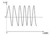
- FIG. 2 shows an example of force data by the vibration generating unit 12 held in the data holding unit 16.
- the force data generated by the vibration generating unit 12 may be determined in advance for each model of the mobile terminal.
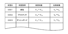
- FIG. 3 shows an example of the first material feature data table held in the data holding unit 16.
- the material ID for identifying the material the material description information, the range of values that the friction coefficient of the material can take, and the range of values that the restitution coefficient of the material can take are associated with each other. Is remembered.
- FIG. 4A shows an example of acceleration data in each of the triaxial directions for each material.
- FIG. 4A shows acceleration data in the X, Y, and Z directions when the material is a carpet (A), and acceleration data in the X, Y, and Z directions when the material is plastic (B).
- the carpet (A) has eyes and directivity in the ease of movement in the in-plane direction
- the plastic (B) has movement in the in-plane direction. There is no directivity in ease.
- the carpet (A) is softer than the plastic (B)
- the acceleration in the Z direction is smaller than that of the plastic.
- FIG. 4B and FIG. 4C show an example of acceleration characteristics determined for each material, focusing on the fact that there are differences in the combinations of values that can be taken by the triaxial acceleration data for each material.
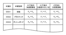
- FIG. 4B shows an example of the second material feature data table held in the data holding unit 16.
- a material ID for identifying the material material, material description information, a range of values that the acceleration amplitude in the X direction can take, a range of values that the acceleration amplitude in the Y direction can take, A range of values that can be taken by the acceleration amplitude in the Z direction is stored in association with each other.
- FIG. 4C shows another example of the second material feature data table held in the data holding unit 16.
- the material ID for identifying the material the material description information
- the range of values that the acceleration amplitude on the XY plane can take the variation in acceleration (deviation, variance) on the XY plane
- a range of values that can be taken by the acceleration amplitude in the Z direction is stored in association with each other.
- the friction coefficient calculation unit 17 calculates a friction coefficient (dynamic friction coefficient) between the object on which the mobile terminal 1 is placed and the mobile terminal 1 based on the acceleration data of the mobile terminal 1 in the in-plane direction of the mobile terminal 1.
- the friction coefficient calculation unit 17 includes the X direction acceleration data recorded in the X direction acceleration data recording unit 14 ⁇ / b> X and the X direction force generated by the vibration generation unit 12 held in the data holding unit 16.
- the friction coefficient in the X direction is calculated on the basis of the above data, and the acceleration data of the portable terminal 1 in the Y direction recorded in the Y direction acceleration data recording unit 14Y and the vibration generating unit 12 held in the data holding unit 16 are used.
- the friction coefficient in the Y direction may be calculated based on the generated Y direction force data. Details of the friction coefficient calculation process will be described later.
- the restitution coefficient calculation unit 18 calculates the restitution coefficient between the surface on which the mobile terminal 1 is placed and the mobile terminal 1 based on the acceleration data of the mobile terminal 1 in the normal direction of the installation surface of the mobile terminal 1. For example, the restitution coefficient calculation unit 18 is based on the normal direction velocity of the installation surface before and after the collision obtained based on the acceleration data of the mobile terminal 1 in the Z direction recorded in the Z direction acceleration data recording unit 14Z. The direction restitution coefficient may be calculated. Details of the processing for calculating the coefficient of restitution will be described later.
- the acceleration amplitude calculation unit 19 calculates the amplitude of acceleration at the time of occurrence of vibration based on the acceleration data recorded in the acceleration data recording unit 14. For example, the acceleration amplitude calculation unit 19 calculates the acceleration amplitude in the X direction based on the acceleration data of the mobile terminal 1 in the X direction recorded in the X direction acceleration data recording unit 14X, and records it in the Y direction acceleration data recording unit 14Y. The Y direction acceleration amplitude is calculated based on the Y direction mobile terminal 1 acceleration data, and the Z direction acceleration is calculated based on the Z direction mobile terminal 1 acceleration data recorded in the Z direction acceleration data recording unit 14Z. The amplitude may be calculated. The acceleration amplitude calculation unit 19 may calculate the acceleration amplitude in the XY plane, the acceleration in the X direction in the XY plane, and the variation in the acceleration in the Y direction.
- the material determination unit 20 is based on at least one of the friction coefficient calculated by the friction coefficient calculation unit 17, the restitution coefficient calculated by the restitution coefficient calculation unit 18, and the acceleration amplitude calculated by the acceleration amplitude calculation unit 19. The material of the object on which the terminal 1 is placed is determined.
- the friction coefficient and the restitution coefficient calculated by the friction coefficient calculation unit 17 from the first material feature data table are calculated.
- the material that includes the restitution coefficient calculated by the unit 18 in the range is searched, and when the material is searched, the searched material may be determined as the material of the object on which the mobile terminal 1 is placed. .
- the material judgment unit 20 searches the second material feature data table for materials each including the triaxial acceleration amplitude in the range.
- the retrieved material may be determined as the material of the object on which the mobile terminal 1 is placed.
- the material determination unit 20 uses the triaxial of the materials searched based on the friction coefficient and the restitution coefficient.
- the material including the material retrieved based on the acceleration amplitude may be determined as the material of the object on which the mobile terminal 1 is placed, or the material retrieved based on the friction coefficient and the restitution coefficient and the triaxial acceleration.
- the material included in either one of the materials searched based on the amplitude may be determined as the material of the object on which the mobile terminal 1 is placed.
- the information processing switching unit 21 executes information processing according to the material determined by the material determining unit 20.
- the material determined by the material determining unit 20 is a predetermined material (for example, a material used for a dashboard of a car) and is calculated from the acceleration data recording unit 14.
- the mobile terminal 1 may output warning information (for example, sound an alert sound).
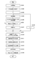
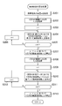
- FIG. 5 shows a flowchart of a material determination process for determining the material of the object on which the mobile terminal 1 is placed, which is executed by the mobile terminal 1.
- the material determination process described below is executed when a periodic timing or a predetermined event (for example, when a determination signal is received or when a strong impact is detected) is detected by the mobile terminal 1. It can be done.
- the mobile terminal 1 performs initial settings (for example, setting of a vibration pattern (data table, vibration time), setting of mass m of the mobile terminal 1, etc.) according to the model and environment. (S101), the number of times of measurement (N times) is also set (S102).
- the number of measurements N may be an integer of 1 or more.
- the mobile terminal 1 initializes the variable i to 1 (S103), starts the generation of vibrations by the vibration generation unit 12 (S104), and sequentially stores acceleration data in the X, Y, and Z directions by corresponding acceleration sensors. Measure and record in association with time (S105).
- the portable terminal 1 If the elapsed time from the start of vibration is not equal to or greater than the threshold T (S106: N), the portable terminal 1 continues to generate vibration and returns to S104 to record triaxial acceleration data. On the other hand, when the elapsed time from the start of vibration becomes equal to or greater than the threshold T (S106: Y), the mobile terminal 1 stops the vibration (S107).
- the mobile terminal 1 increments the variable i (adds 1) (S109), and sets a predetermined time interval. After waiting, the process of S104 may be started. If the variable i has reached N in S108 (S108: Y), the mobile terminal 1 performs noise cancellation processing on the recorded acceleration data (S110), and then stores the recorded acceleration data in the recorded acceleration data. Based on this, a friction coefficient calculation process is executed (S111). Details of the friction coefficient calculation processing will be described with reference to the flowchart shown in FIG.
- FIG. 6 shows a flowchart of the friction coefficient calculation process.
- the mobile terminal 1 acquires the mass m of the mobile terminal 1 (S201), and acquires data on the force F x (t) due to vibration in the X direction from the data holding unit 16 (S202). .
- the mobile terminal 1 initializes the variable i to 1 (S203), and sets the dynamic friction coefficient ⁇ xi based on the acceleration a x (t) in the X direction, the force F x (t), and the mass m in the i-th measurement data.
- Calculate (S204). Time t is set to 0 when vibration starts.
- the dynamic friction coefficient calculation processing may be performed based on the physical model shown in FIG.
- the mobile terminal 1 is placed on the target object 2, and the mass M of the target object 2 is sufficiently heavier than the mass m of the mobile terminal 1.
- the mass is infinite (the object is fixed).
- the vibration generator (vibrator) provided in the mobile terminal 1 is sufficiently lighter than the mass m of the mobile terminal 1 and the mass of the vibration generating unit 12 is infinitely small (0).
- the motion change in the Z direction is not considered, and F cx (t) operates with a predetermined force, and the mobile terminal 1, the object 2, and the vibration generator 12 are rigid bodies.
- the dynamic friction coefficient ⁇ calculated in the X direction is calculated by the following equation (1).
- N is vertical drag and is equal to mg.
- the mobile terminal 1 increments (adds 1) the variable i (S206), returns to S204, and if the variable i reaches N (S205: Y), the process proceeds to S207.
- the mobile terminal 1 calculates the X-direction of the dynamic friction coefficient ⁇ x (S207). For example, the mobile terminal 1 may calculate the average value of ⁇ x1 to ⁇ xN as ⁇ x .
- the portable terminal 1 acquires data of the force F Y (t) due to vibration in the Y direction from the data holding unit 16 (S208), initializes the variable i to 1 (S209), and the i-th measurement data
- the dynamic friction coefficient ⁇ yi is calculated by the equation (1) based on the acceleration a y (t), the force F y (t), and the mass m in the Y direction (S210). Time t is set to 0 when vibration starts.
- the mobile terminal 1 increments (adds 1) the variable i (S212), returns to S210, and when the variable i reaches N (S211: Y), the process proceeds to S213.
- the mobile terminal 1 based on the measured one to each dynamic friction coefficient mu y1 ⁇ mu yN calculated for the N, to calculate the dynamic friction coefficient mu y in the Y direction (S213), the process returns. For example, the mobile terminal 1 may calculate the average value of ⁇ y1 to ⁇ yN as ⁇ y .
- the mobile terminal 1 After completing the calculation process of the friction coefficient, the mobile terminal 1 next executes the calculation process of the restitution coefficient based on the recorded acceleration data (S112). Details of the processing for calculating the coefficient of restitution will be described based on the flowchart shown in FIG.
- the mobile terminal 1 initializes the variable i to 1 (S301), and based on the acceleration a z (t) in the Z direction in the i-th measurement data, the mobile terminal 1 and the object calculating a collision time t 1 with (S302).
- the time t is set to 0 at the start of vibration, and the coordinate position in the Z direction at the start of vibration is set to 0.
- the mobile terminal 1 increments (adds 1) the variable i (S307), returns to S302, and if the variable i reaches N (S306: Y), the process proceeds to S308.
- the mobile terminal 1 calculates the restitution coefficient e based on the restitution coefficients e 1 to e N calculated for each of the measurements 1 to N (S308), and returns. For example, the mobile terminal 1 may calculate the average value of e 1 to e N as e.
- the portable terminal 1 next executes the calculation process of the acceleration amplitude based on the recorded acceleration data (S113). The details of the acceleration amplitude calculation process will be described based on the flowchart shown in FIG.
- the mobile terminal 1 initializes the variable i to 1 (S401), calculates the acceleration amplitude Axi in the X direction in the i-th measurement data (S402), and the i-th measurement data.
- the Y-direction acceleration amplitude A yi is calculated (S403), and the Z-direction acceleration amplitude A Zi in the i-th measurement data is calculated (S404).
- the acceleration amplitude may be the difference between the maximum value and the minimum value of acceleration that appear periodically.
- the mobile terminal 1 increments the variable i (adds 1) (S406), returns to S402, and when the variable i reaches N (S405: Y), the process proceeds to S407.
- Portable terminal 1 on the basis of the acceleration amplitude A x1 ⁇ A xN of X direction calculated regarding each of the 1st to N-th time measurement, to calculate the acceleration amplitude A x of the X direction (S407), measuring 1 Based on the Y-direction acceleration amplitudes A y1 to A yN calculated for each of .about.N , the Y-direction acceleration amplitude A y is calculated (S408) and calculated for each of the first to N-th measurements. Based on the acceleration amplitudes A z1 to A zN in the Z direction, the acceleration amplitude A z in the Z direction is calculated (S409), and the process returns.
- the mobile terminal 1 may calculate the average value of A x1 to A xN as A x , the average value of A y1 to A yN as A y , and the average value of A z1 to A zN as A z .
- the mobile terminal 1 determines the material of the object on which the mobile terminal 1 is placed based on at least one of the calculated friction coefficient, restitution coefficient, and acceleration amplitude (S114). ). A specific example of the material determination process will be described below.
- the mobile terminal 1 determines the material using the friction coefficient and the restitution coefficient
- the range of the friction coefficient calculated in S111 and the restitution coefficient calculated in S112 is selected from the first material feature data table.
- the identification information (material ID) of the material included in is searched.
- the mobile terminal 1 returns an error,
- the material may be determined using the triaxial acceleration amplitude calculated in S113.
- the triaxial acceleration amplitude (X, Y, and X) calculated in S113 is selected from the second material feature data table.
- the material identification information (material ID) including the respective acceleration amplitudes in the Z direction) is searched.
- the portable terminal 1 holds the magnitude of acceleration amplitude in the XY plane and the range of variation (deviation) of acceleration in the X and Y directions in the second material feature data table.
- the acceleration amplitude magnitude A xy in the XY plane is calculated based on the acceleration amplitude in the X direction and the acceleration amplitude in the Y direction, and the acceleration amplitude in the X direction and the Y direction in the first to Nth measurements are calculated.
- the deviation ⁇ indicating the scale of variation based on the value taken by the acceleration amplitude of A may be calculated, and material identification information (material ID) including A xy , the deviation ⁇ , and the acceleration amplitude A z in the Z direction as a range may be searched.
- the portable terminal 1 may return an error when the material identification information (material ID) corresponding to the acceleration amplitude calculated in S113 is not searched.
- the portable terminal 1 uses material ID contained in material ID determined using acceleration amplitude among material ID determined using the friction coefficient and the restitution coefficient as material ID of the surface where the portable terminal 1 was placed. It may be determined.
- the portable terminal 1 may execute information processing according to the material determined in S114 (S115). For example, the mobile terminal 1 may change the intensity of vibration according to the material determined in S114. If the material determined in S114 is a dashboard of an automobile, the mobile terminal 1 An alert sound may be output, or when the material determined in S114 is a carpet, the operation when the mobile terminal 1 is received may be switched from vibration to sound effect. In addition, when a request for searching for a place where the mobile terminal 1 is placed is received, the material determination process is executed, and the information on the determined material is output by voice, so that the user finds the mobile terminal 1. It becomes easy.
- the mobile terminal 1 can determine the material of the object on which the mobile terminal 1 is placed and can execute processing according to the determined material.
- the present invention is not limited to the above-described embodiment.
- the material determination process is performed based on the friction coefficient, the rebound count, and the acceleration amplitude information calculated by the mobile terminal 1, but the calculated friction coefficient, the restitution count, and the acceleration amplitude information are used. It may be transmitted to the server, the corresponding material is determined based on the friction coefficient, the rebound count, and the acceleration amplitude information transmitted by the server, and the result may be transmitted to the mobile terminal 1.
- the acceleration data recorded by the mobile terminal 1 may be transmitted to the server, and the server may calculate the friction coefficient, the rebound count, and the acceleration amplitude information.
Landscapes
- Engineering & Computer Science (AREA)
- Signal Processing (AREA)
- Physics & Mathematics (AREA)
- General Physics & Mathematics (AREA)
- Environmental & Geological Engineering (AREA)
- Human Computer Interaction (AREA)
- Computer Networks & Wireless Communication (AREA)
- Telephone Function (AREA)
Abstract
Description
本発明は、携帯端末、携帯端末状態判定システム、プログラム、記憶媒体及び携帯端末状態判定方法に関する。
着信等のイベント発生をユーザに知らせるための振動発生機能を備えた携帯端末がある。例えば、特許文献1に記載の発明のように、携帯端末が硬い物の上に置かれている場合には、振動の発生を停止させているものがある。このように、携帯端末が置かれている状況が判明すれば、その状況に応じた処理を実行させることが可能となる。
本発明の目的は、携帯端末が置かれている物体の材質を特定できる携帯端末、携帯端末状態判定システム及びプログラムを提供することにある。
請求項1に記載の発明は、携帯端末の加速度を計測する加速度計測手段と、前記携帯端末が対象物上に置かれた状態で、前記携帯端末を振動させた際の前記加速度計測手段により計測される加速度に基づいて、前記対象物に接触する面内方向に対する第1の特徴量と面外方向に対する第2の特徴量を算出する算出手段と、前記第1の特徴量と前記第2の特徴量に基づき前記対象物の材質を特定する特定手段と、を含む携帯端末である。
請求項2に記載の発明は、前記特定手段は、1以上の材質ごとに、第1の特徴量の範囲と、第2の特徴量の範囲とをそれぞれ関連付けて記憶した記憶手段から、前記算出手段により算出された前記第1の特徴量と前記第2の特徴量とに基づき前記対象物の材質を特定する、請求項1に記載の携帯端末である。
請求項3に記載の発明は、前記第1の特徴量は、前記面内方向における第1の方向と、第2の方向とのそれぞれについて前記加速度計測手段により計測される加速度の振幅を含み、前記第2の特徴量は、前記面外方向について前記加速度計測手段により計測される加速度の振幅を含む、請求項1又は2に記載の携帯端末である。
請求項4に記載の発明は、前記携帯端末は、当該携帯端末を振動させる振動発生手段を備え、前記算出手段は、前記面内方向について前記振動発生手段により発生する力と、前記面内方向について前記加速度計測手段により計測される加速度と、前記携帯端末の質量とに基づいて前記携帯端末と前記対象物の動摩擦係数を算出し、前記第1の特徴量は、前記動摩擦係数を含む、請求項1乃至3に記載の携帯端末である。
請求項5に記載の発明は、前記算出手段は、前記加速度計測手段により計測される加速度に基づいて算出される、前記携帯端末が前記対象物に衝突する前の前記面外方向の速度と、前記携帯端末が前記対象物に衝突した後の前記面外方向の速度とに基づいて、前記携帯端末と前記対象物の反発係数を算出し、前記第2の特徴量は、前記反発係数を含む、請求項1乃至3に記載の携帯端末である。
請求項6に記載の発明は、加速度を計測する加速度計測手段を備える携帯端末と、前記携帯端末が対象物上に置かれた状態で、前記携帯端末を振動させた際の前記加速度計測手段により計測される加速度に基づいて、前記対象物に接触する面内方向に対する第1の特徴量と面外方向に対する第2の特徴量を算出する算出手段と、前記第1の特徴量と前記第2の特徴量に基づき前記対象物の材質を特定する特定手段と、を含む携帯端末状態判定システムである。
請求項7に記載の発明は、携帯端末の加速度を計測する加速度計測手段と、前記携帯端末が対象物上に置かれた状態で、前記携帯端末を振動させた際の前記加速度計測手段により計測される加速度に基づいて、前記対象物に接触する面内方向に対する第1の特徴量と面外方向に対する第2の特徴量を算出する算出手段と、前記第1の特徴量と前記第2の特徴量に基づき前記対象物の材質を特定する特定手段としてコンピュータを機能させるためのプログラムである。
請求項8に記載の発明は、携帯端末の加速度を計測する加速度計測手段と、前記携帯端末が対象物上に置かれた状態で、前記携帯端末を振動させた際の前記加速度計測手段により計測される加速度に基づいて、前記対象物に接触する面内方向に対する第1の特徴量と面外方向に対する第2の特徴量を算出する算出手段と、前記第1の特徴量と前記第2の特徴量に基づき前記対象物の材質を特定する特定手段としての機能をコンピュータに実行させるプログラムを格納したことを特徴とするコンピュータが読取可能な記憶媒体である。
請求項9に記載の発明は、携帯端末の加速度を計測し、前記携帯端末が対象物上に置かれた状態で、前記携帯端末を振動させた際に計測した加速度に基づいて、前記対象物に接触する面内方向に対する第1の特徴量と面外方向に対する第2の特徴量を算出し、前記第1の特徴量と前記第2の特徴量に基づき前記対象物の材質を特定する、ことを特徴とする携帯端末状態判定方法である。
請求項1及び6ないし9に記載の発明によれば、携帯端末が置かれている物体の材質を特定できる。
請求項2に記載の発明によれば、材質ごとに、特徴量の範囲を関連付けて、物体の材質を特定できる。
請求項3に記載の発明によれば、加速度の振幅を用いて、物体の材質を特定できる。
請求項4に記載の発明によれば、携帯端末が置かれている物体との動摩擦係数から、物体の材質を特定できる。
請求項5に記載の発明によれば、携帯端末が置かれている物体との反発係数から、物体の材質を特定できる。
以下、本発明を実施するための実施の形態(以下、実施形態という)を、図面に従って説明する。本実施形態に係る携帯端末1は、振動機能(バイブレーション機能)を備え、携帯端末1の振動時に計測される加速度データに基づいて、携帯端末1が置かれた物体の材質を判定する処理を行う。
[1.機能ブロック図の説明]
図1には、本実施形態に係る携帯端末1の機能ブロック図を示した。図1に示されるように、携帯端末1は、計測制御部11、振動発生部12、加速度検出部13、加速度データ記録部14、データ取得部15、データ保持部16、摩擦係数算出部17、反発係数算出部18、加速度振幅算出部19、材質判定部20、情報処理切替部21を備える。
携帯端末1に備えられる上記の各部の機能は、CPU等の制御手段、メモリ等の記憶手段、外部デバイスとデータを送受信する通信手段、振動発生器(バイブレータ)、3方向のそれぞれの加速度を検出する加速度センサ等を備えたコンピュータが、コンピュータ読み取り可能な情報記憶媒体に格納されたプログラムを読み込み実行することで実現されるものとしてよい。なお、プログラムは光ディスク、磁気ディスク、磁気テープ、光磁気ディスク、フラッシュメモリ等の情報記憶媒体によってコンピュータたる携帯端末1に供給されることとしてもよいし、インターネット等のデータ通信網を介して携帯端末1に供給されることとしてもよい。なお、携帯端末1は、携帯電話機(フィーチャーフォン、スマートフォンを含む)、タブレット端末、ノートパソコン、PDA等としてよい。
計測制御部11は、計測の開始及び終了、振動発生部12の振動の開始及び停止等を制御する。例えば、計測制御部11は、計測を実行するタイミングが到来した場合に、計測条件(計測回数、振動時間等)を設定するとともに、設定した計測条件に従って振動発生部12に振動の開始と停止とを実行させる。また、計測の実行タイミングは、予め定められた時間間隔ごととしてもよいし、携帯端末1において予め定められたイベントが発生したタイミングとしてもよいし、携帯端末1において他のデバイスから予め定められた信号を受信したタイミングとしてもよい。
振動発生部12は、例えば重りと、重りを回転させるモータを含み構成され、計測制御部11による制御に従って携帯端末1を振動させる。振動発生部12は、計測制御部11により指定されたタイミング(T1)で振動を開始し、計測制御部11により指定されたタイミング(T2(<T1))まで振動を継続した後に振動を停止する処理を、指定された回数繰り返すこととする。
加速度検出部13は、例えば加速度センサを含み構成され、携帯端末1の加速度を検出する。加速度検出部13は、X方向加速度検出部13X、Y方向加速度検出部13Y、Z方向加速度検出部13Zを有し、携帯端末1の物体に対する設置面の面内方向と、設置面の面外方向(例えば法線方向)の3方向の加速度をそれぞれ検出するようになっている。なお、本実施形態においては、X,Y方向が携帯端末1の設置面(ディスプレイが設けられている表面又はその裏面)の面内方向の方向に対応しており、Z方向が設置面に対する法線方向に対応している。
加速度データ記録部14は、計測制御部11による制御に応じて振動発生部12により発生した振動に基づいて加速度検出部13により検出される加速度データを時間に関連付けて記録する。加速度データ記録部14は、X方向加速度データ記録部14X、Y方向加速度データ記録部14Y、Z方向加速度データ記録部14Zを有し、携帯端末1の設置面内方向(X,Y方向)と、設置面の法線方向(Z方向)の3方向の加速度データを計測時刻に関連付けてそれぞれ記録する。
データ取得部15は、携帯端末1の設置面の材質判定処理に利用するデータ(利用データ)を取得する。データ取得部15は、予め定められたデバイス(サーバ)から利用データをダウンロードすることとしてもよいし、利用データを格納した記憶媒体から利用データを読み出すこととしてもよい。例えば、データ取得部15は、計測開始時に、予め定められたデバイスへの通信が可能である場合には、予め定められたデバイスから最新の利用データをダウンロードし、予め定められたデバイスへの通信が可能でない場合には、既に取得されている利用データを利用するようにしてもよい。
例えば、データ取得部15により取得される利用データには、振動発生部12による振動によるX,Y,Z方向に発生する力の時間ごとの推移情報、材質ごとの摩擦係数、反発係数の範囲を定めたデータや、材質ごとのX,Y,Z方向の加速度振幅の範囲を定めたデータ等が含まれる。
データ保持部16は、データ取得部15により取得された利用データを保持する。以下、データ保持部16により保持されるデータの一例を説明する。
図2には、データ保持部16に保持される振動発生部12による力のデータの一例を示した。図2に示される例では、横軸に時間t(t=0で振動開始)、縦軸に力(N)を表す。振動発生部12による力のデータは、携帯端末の機種ごとに予め定められていることとしてよい。
図3には、データ保持部16に保持される第1の材質特徴データテーブルの一例を示した。図3に示される第1の材質特徴データテーブルでは、材質を識別する材質ID、材質の説明情報、材質の摩擦係数が取り得る値の範囲、材質の反発係数が取り得る値の範囲がそれぞれ関連付けて記憶される。
図4Aには、材質ごとの3軸方向のそれぞれの加速度データの一例を示した。図4Aには材質が絨毯(A)である場合のX,Y,Z方向の加速度のデータ、材質がプラスチック(B)である場合のX,Y,Z方向の加速度のデータを示している。図4Aに示されるように、絨毯(A)には目があり、面内方向の移動のし易さに指向性があるのに対して、プラスチック(B)には、面内方向の移動のし易さには指向性がない。また、絨毯(A)はプラスチック(B)と比べて柔らかいため、Z方向の加速度がプラスチックに比べて小さくなる。このように、材質ごとに3軸の加速度データの取り得る値の組合せには差異が生じる。図4B及び図4Cには、材質ごとに3軸の加速度データの取り得る値の組合せには差異が生じる点に着目し、材質ごとに定めた加速度特徴の一例を示す。
図4Bには、データ保持部16に保持される第2の材質特徴データテーブルの一例を示した。図4Bに示される第2の材質特徴データテーブルでは、材質を識別する材質ID、材質の説明情報、X方向の加速度振幅が取り得る値の範囲、Y方向の加速度振幅が取り得る値の範囲、Z方向の加速度振幅が取り得る値の範囲がそれぞれ関連付けて記憶される。
図4Cには、データ保持部16に保持される第2の材質特徴データテーブルの他の一例を示した。図4Bに示される第2の材質特徴データテーブルでは、材質を識別する材質ID、材質の説明情報、XY平面における加速度振幅が取り得る値の範囲、XY平面における加速度のばらつき(偏差、分散)、Z方向の加速度振幅が取り得る値の範囲がそれぞれ関連付けて記憶される。
摩擦係数算出部17は、携帯端末1の設置面内方向の携帯端末1の加速度データに基づいて携帯端末1が置かれている物体と携帯端末1との摩擦係数(動摩擦係数)を算出する。例えば、摩擦係数算出部17は、X方向加速度データ記録部14Xに記録されたX方向の携帯端末1の加速度データと、データ保持部16に保持された振動発生部12により発生するX方向の力のデータとに基づいてX方向の摩擦係数を算出し、Y方向加速度データ記録部14Yに記録されたY方向の携帯端末1の加速度データと、データ保持部16に保持された振動発生部12により発生するY方向の力のデータとに基づいてY方向の摩擦係数を算出することとしてよい。この摩擦係数の算出処理の詳細については後述する。
反発係数算出部18は、携帯端末1の設置面の法線方向についての携帯端末1の加速度データに基づいて携帯端末1が置かれている面と携帯端末1との反発係数を算出する。例えば、反発係数算出部18は、Z方向加速度データ記録部14Zに記録されたZ方向の携帯端末1の加速度データに基づいて得られる衝突前後の設置面の法線方向の速度に基づいて、Z方向の反発係数を算出することとしてよい。この反発係数の算出処理の詳細についても後述する。
加速度振幅算出部19は、加速度データ記録部14に記録された加速度データに基づいて、振動発生時の加速度の振幅を算出する。例えば、加速度振幅算出部19は、X方向加速度データ記録部14Xに記録されたX方向の携帯端末1の加速度データに基づいてX方向の加速度振幅を算出し、Y方向加速度データ記録部14Yに記録されたY方向の携帯端末1の加速度データに基づいてY方向の加速度振幅を算出し、Z方向加速度データ記録部14Zに記録されたZ方向の携帯端末1の加速度データに基づいてZ方向の加速度振幅を算出することとしてよい。また、加速度振幅算出部19は、XY面内における加速度の振幅、XY面内におけるX方向の加速度、Y方向の加速度のばらつきを算出することとしてもよい。
材質判定部20は、摩擦係数算出部17により算出された摩擦係数、反発係数算出部18により算出された反発係数、加速度振幅算出部19により算出された加速度振幅の少なくとも1つに基づいて、携帯端末1が置かれている物体の材質を判定する。
例えば、材質判定部20は、材質の判定に摩擦係数と反発係数とを用いる場合には、第1の材質特徴データテーブルの中から、摩擦係数算出部17により算出された摩擦係数、反発係数算出部18により算出された反発係数とをそれぞれ範囲に含む材質を検索し、材質が検索された場合には、当該検索された材質を携帯端末1が置かれた物体の材質と判定することとしてよい。
また、例えば、材質判定部20は、材質の判定に3軸の加速度振幅を用いる場合には、第2の材質特徴データテーブルの中から、3軸の加速度振幅をそれぞれ範囲に含む材質を検索し、材質が検索された場合には、当該検索された材質を携帯端末1が置かれた物体の材質と判定することとしてよい。
また、例えば、材質判定部20は、材質の判定に摩擦係数及び反発係数と、3軸の加速度振幅を用いる場合には、摩擦係数及び反発係数に基づいて検索された材質のうち、3軸の加速度振幅に基づいて検索された材質が含まれる材質を携帯端末1が置かれた物体の材質と判定することとしてもよいし、摩擦係数及び反発係数に基づいて検索された材質と3軸の加速度振幅に基づいて検索された材質のうちどちらか一方に含まれる材質を携帯端末1が置かれた物体の材質と判定することとしてもよい。
情報処理切替部21は、材質判定部20により判定された材質に応じた情報処理を実行する。例えば、情報処理切替部21は、材質判定部20により判定された材質が予め定められた材質(例えば車のダッシュボードに用いられる素材)であって、加速度データ記録部14から算出される面内方向の移動量が閾値を超えている場合に、携帯端末1に警告情報を出力させる(例えばアラート音を鳴らす等)ようにしてもよい。
[2.フローチャートの説明]
次に、本実施形態に係る携帯端末1により実行される処理の一例を図5乃至図8に示したフローチャートを参照しながら説明する。
[2-1.材質判定処理]
図5には、携帯端末1により実行される携帯端末1の置かれている物体の材質を判定する材質判定処理のフローチャートを示した。以下、説明する材質判定処理は、携帯端末1により定期的なタイミング又は、予め定められたイベント(例えば判定の信号を受信した場合や、強い衝撃を検知した場合等)が検出された場合に実行されることとしてよい。
図5に示されるように、携帯端末1は、機種・環境に応じた初期設定(例えば、振動パターン(データテーブル、振動時間)の設定、携帯端末1の質量mの設定等)を実行するとともに(S101)、計測回数(N回)についても設定する(S102)。計測回数Nは、1以上の整数としてよい。
携帯端末1は、変数iを1に初期化して(S103)、振動発生部12による振動の発生を開始し(S104)、X,Y,Z方向の加速度データをそれぞれに対応した加速度センサにより順次計測し、時間に関連付けて記録する(S105)。
携帯端末1は、振動開始からの経過時間が閾値T以上となっていない場合には(S106:N)、振動の発生を継続するとともに、S104に戻って、3軸の加速度データを記録する。一方で、携帯端末1は、振動開始からの経過時間が閾値T以上となった場合には(S106:Y)、振動を停止させる(S107)。
携帯端末1は、振動を停止させた後に、変数iがNに達していない場合には(S108:N)、変数iをインクリメント(1加算)して(S109)、予め定められた時間間隔を待機した後に、S104の処理を開始することとしてよい。また、携帯端末1は、S108で、変数iがNに達している場合には(S108:Y)、記録された加速度データのノイズキャンセル処理を行った後に(S110)、記録された加速度データに基づいて摩擦係数の算出処理を実行する(S111)。この摩擦係数の算出処理の詳細については、図6に示したフローチャートに基づき説明する。
[2-2.摩擦係数算出処理]
図6には、摩擦係数算出処理のフローチャートを示した。図6に示されるように、携帯端末1は、携帯端末1の質量mを取得し(S201)、データ保持部16からX方向の振動による力Fx(t)のデータを取得する(S202)。
携帯端末1は、変数iを1に初期化して(S203)、i回目の計測データにおけるX方向の加速度ax(t)、力Fx(t)、質量mに基づいて動摩擦係数μxiを算出する(S204)。なお、時間tは、振動開始時を0とする。ここで、動摩擦係数の算出処理は、図9に示した物理モデルに基づいて行うこととしてよい。
図9に示した物理モデルの例では、携帯端末1が対象物2に置かれていることとし、対象物2の質量Mは携帯端末1の質量mに比べて十分に重く、対象物2の質量を無限大(対象物は固定されている)と仮定する。また、携帯端末1に備えられた振動発生器(バイブレータ)は、携帯端末1の質量mに比べて十分に軽く、振動発生部12の質量は無限小(0)と仮定する。さらに、Z方向の運動変化は考慮せず、Fcx(t)は、予め定められた力で動作することとし、携帯端末1、対象物2、振動発生部12は互いに剛体であるとする。この場合に、X方向に関して算出される動摩擦係数μは、以下の式(1)により算出される。なお、Nは垂直抗力でmgに等しい。

携帯端末1は、変数iがNに達していない場合には(S205:N)、変数iをインクリメント(1加算)して(S206)、S204に戻り、変数iがNに達した場合には(S205:Y)、S207に進む。
携帯端末1は、第1回~第N回の計測のそれぞれについて算出された動摩擦係数μx1~μxNに基づいて、X方向の動摩擦係数μxを算出する(S207)。例えば、携帯端末1は、μx1~μxNの平均値をμxとして算出することとしてよい。
次に、携帯端末1は、データ保持部16からY方向の振動による力FY(t)のデータを取得し(S208)、変数iを1に初期化して(S209)、i回目の計測データにおけるY方向の加速度ay(t)、力Fy(t)、質量mに基づいて動摩擦係数μyiを(1)式により算出する(S210)。なお、時間tは、振動開始時を0とする。
携帯端末1は、変数iがNに達していない場合には(S211:N)、変数iをインクリメント(1加算)して(S212)、S210に戻り、変数iがNに達した場合には(S211:Y)、S213に進む。
携帯端末1は、計測1~Nのそれぞれについて算出された動摩擦係数μy1~μyNに基づいて、Y方向の動摩擦係数μyを算出し(S213)、リターンする。例えば、携帯端末1は、μy1~μyNの平均値をμyとして算出することとしてよい。
ここで、図5のフローチャートに戻り説明を続ける。携帯端末1は、摩擦係数の算出処理を終えると、次に、記録された加速度データに基づいて反発係数の算出処理を実行する(S112)。この反発係数の算出処理の詳細については、図7に示したフローチャートに基づいて説明する。
[2-3.反発係数算出処理]
図7に示されるように、携帯端末1は、変数iを1に初期化して(S301)、i回目の計測データにおけるZ方向の加速度az(t)に基づいて、携帯端末1と対象物との衝突時刻t1を算出する(S302)。なお、時間tは、振動開始時を0とし、振動開始時のZ方向の座標位置は0とする。
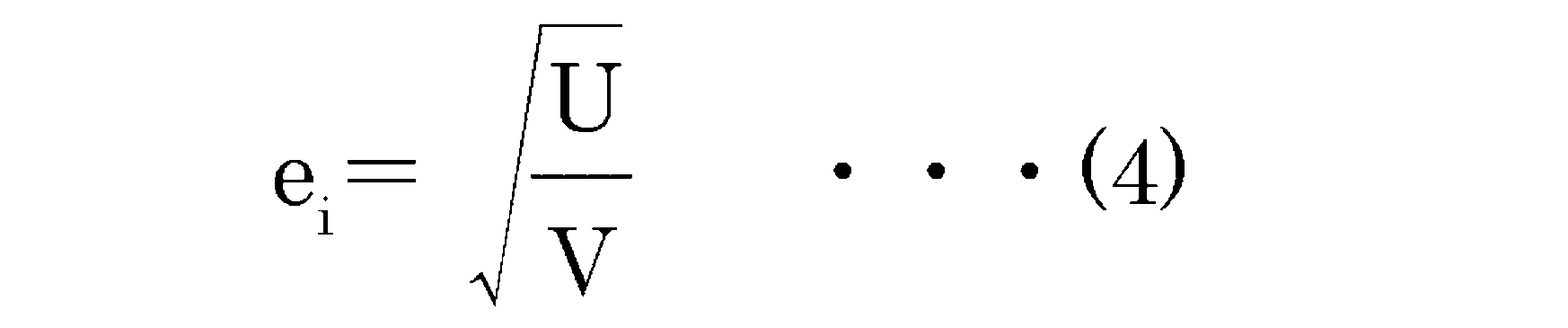
携帯端末1は、i回目の計測データにおけるZ方向の加速度az(t)に基づいて、衝突時刻t1の直前t1A(t1A=t1-Δt)の速度Vを以下の式(2)により算出するとともに(S303)、衝突時刻t1の直後t1B(t1B=t1+Δt)の速度Uを以下の式(3)により算出する(S304)。そして、携帯端末1は、算出されたVとUとに基づいて反発係数eiを以下の式(4)により算出する(S305)。


携帯端末1は、変数iがNに達していない場合には(S306:N)、変数iをインクリメント(1加算)して(S307)、S302に戻り、変数iがNに達した場合には(S306:Y)、S308に進む。
携帯端末1は、計測1~Nのそれぞれについて算出された反発係数e1~eNに基づいて、反発係数eを算出し(S308)、リターンする。例えば、携帯端末1は、e1~eNの平均値をeとして算出することとしてよい。
次に、図5のフローチャートに戻り説明を続ける。携帯端末1は、反発係数の算出処理を終えると、次に、記録された加速度データに基づいて加速度振幅の算出処理を実行する(S113)。この加速度振幅の算出処理の詳細については、図8に示したフローチャートに基づき説明する。
[2-4.加速度振幅算出処理]
図8に示されるように、携帯端末1は、変数iを1に初期化して(S401)、i回目の計測データにおけるX方向の加速度振幅Axiを算出し(S402)、i回目の計測データにおけるY方向の加速度振幅Ayiを算出し(S403)、i回目の計測データにおけるZ方向の加速度振幅AZiを算出する(S404)。なお、加速度振幅は、周期的に現れる加速度の最大値と最小値との差としてよい。
携帯端末1は、変数iがNに達していない場合には(S405:N)、変数iをインクリメント(1加算)して(S406)、S402に戻り、変数iがNに達した場合には(S405:Y)、S407に進む。
携帯端末1は、第1回~第N回の計測のそれぞれについて算出されたX方向の加速度振幅Ax1~AxNに基づいて、X方向の加速度振幅Axを算出し(S407)、計測1~Nのそれぞれについて算出されたY方向の加速度振幅Ay1~AyNに基づいて、Y方向の加速度振幅Ayを算出し(S408)、第1回~第N回の計測のそれぞれについて算出されたZ方向の加速度振幅Az1~AzNに基づいて、Z方向の加速度振幅Azを算出し(S409)、リターンする。例えば、携帯端末1は、Ax1~AxNの平均値をAx、Ay1~AyNの平均値をAy、Az1~AzNの平均値をAzとして算出することとしてよい。
ここで、図5のフローチャートに戻り説明を続ける。携帯端末1は、加速度振幅の算出処理を終えると、算出された摩擦係数、反発係数、加速度振幅の少なくとも1つに基づいて、携帯端末1が置かれている対象物の材質を判定する(S114)。以下、材質の判定処理の具体例について説明する。
携帯端末1は、摩擦係数と反発係数を用いて材質を判定する場合には、第1の材質特徴データテーブルの中から、S111で算出された摩擦係数、S112で算出された反発係数をそれぞれ範囲に含む材質の識別情報(材質ID)を検索する。ここで、携帯端末1は、S111で算出された摩擦係数、S112で算出された反発係数をそれぞれ範囲に含む材質の識別情報(材質ID)が検索されなかった場合には、エラーを返すか、S113で算出された3軸の加速度振幅を用いて材質を判定することとしてよい。
ここで、携帯端末1は、3軸の加速度振幅を用いて材質を判定する場合には、第2の材質特徴データテーブルの中から、S113で算出された3軸の加速度振幅(X,Y,Z方向のそれぞれの加速度振幅)をそれぞれ範囲に含む材質の識別情報(材質ID)を検索する。ここで、携帯端末1は、XY平面内の加速度振幅の大きさと、X,Y方向のそれぞれの加速度の変動量(偏差)の範囲を第2の材質特徴データテーブルに保持しておく場合には、X方向の加速度振幅と、Y方向の加速度振幅とに基づいてXY平面内の加速度振幅の大きさAxyを算出するとともに、第1~第N回の計測におけるX方向の加速度振幅とY方向の加速度振幅の取る値に基づくばらつきの尺度を示す偏差σを算出し、Axy、偏差σ、Z方向の加速度振幅Azを範囲として含む材質の識別情報(材質ID)を検索することとしてよい。ここで、携帯端末1は、S113で算出された加速度振幅に対応した材質の識別情報(材質ID)が検索されなかった場合には、エラーを返すこととしてよい。
また、携帯端末1は、摩擦係数と反発係数を用いて判定した材質IDのうち、加速度振幅を用いて判定した材質IDに含まれる材質IDを、携帯端末1が置かれた面の材質IDとして判定することとしてもよい。
携帯端末1は、S114で判定された材質に応じた情報処理を実行することとしてよい(S115)。例えば、携帯端末1は、S114で判定された材質に応じてバイブレーションの強度を変えるようにしてもよいし、S114で判定された材質が、自動車のダッシュボードである場合には、携帯端末1にアラート音を出力させることとしてもよいし、S114で判定された材質が、絨毯である場合には、携帯端末1の着信時の動作をバイブレーションから効果音に切り替えるようにしてもよい。また、携帯端末1の置かれた場所を検索する要求を受け付けた場合に、材質の判定処理を実行し、判定された材質の情報を音声出力するようにすれば、ユーザが携帯端末1を見つけやすくなる。
以上説明した本実施形態に係る携帯端末1は、自らが置かれた物体の材質を判定し、判定された材質に応じた処理を実行できる。
また、本発明は、上述した実施形態に限定されるものではない。例えば、本実施形態では、携帯端末1が算出した摩擦係数、反発計数、加速度振幅の情報に基づいて材質の判定処理を実行しているが、算出した摩擦係数、反発計数、加速度振幅の情報をサーバに送信し、サーバが送信された摩擦係数、反発計数、加速度振幅の情報に基づいて対応する材質を判定して、その結果を携帯端末1に送信するようにしてもよい。また、携帯端末1が記録した加速度のデータをサーバに送信して、サーバにおいて摩擦係数、反発計数、加速度振幅の情報を算出するようにしてもよい。
1 携帯端末、2 対象物、11 計測制御部、12 振動発生部、13 加速度検出部、13X X方向加速度検出部、13Y Y方向加速度検出部、13Z Z方向加速度検出部、14 加速度データ記録部、14X X方向加速度データ記録部、14Y Y方向加速度データ記録部、14Z Z方向加速度データ記録部、15 データ取得部、16
データ保持部、17 摩擦係数算出部、18 反発係数算出部、19 加速度振幅算出部、20 材質判定部、21 情報処理切替部。
Claims (9)
-
携帯端末の加速度を計測する加速度計測手段と、
前記携帯端末が対象物上に置かれた状態で、前記携帯端末を振動させた際の前記加速度計測手段により計測される加速度に基づいて、前記対象物に接触する面内方向に対する第1の特徴量と面外方向に対する第2の特徴量を算出する算出手段と、
前記第1の特徴量と前記第2の特徴量に基づき前記対象物の材質を特定する特定手段と、を含む携帯端末。
-
前記特定手段は、1以上の材質ごとに、第1の特徴量の範囲と、第2の特徴量の範囲とをそれぞれ関連付けて記憶した記憶手段から、前記算出手段により算出された前記第1の特徴量と前記第2の特徴量とに基づき前記対象物の材質を特定する、
請求項1に記載の携帯端末。
-
前記第1の特徴量は、前記面内方向における第1の方向と、第2の方向とのそれぞれについて前記加速度計測手段により計測される加速度の振幅を含み、
前記第2の特徴量は、前記面外方向について前記加速度計測手段により計測される加速度の振幅を含む、
請求項1又は2に記載の携帯端末。
-
前記携帯端末は、当該携帯端末を振動させる振動発生手段を備え、
前記算出手段は、前記面内方向について前記振動発生手段により発生する力と、前記面内方向について前記加速度計測手段により計測される加速度と、前記携帯端末の質量とに基づいて前記携帯端末と前記対象物の動摩擦係数を算出し、
前記第1の特徴量は、前記動摩擦係数を含む、
請求項1乃至3に記載の携帯端末。
-
前記算出手段は、前記加速度計測手段により計測される加速度に基づいて算出される、前記携帯端末が前記対象物に衝突する前の前記面外方向の速度と、前記携帯端末が前記対象物に衝突した後の前記面外方向の速度とに基づいて、前記携帯端末と前記対象物の反発係数を算出し、
前記第2の特徴量は、前記反発係数を含む、
請求項1乃至3に記載の携帯端末。
-
加速度を計測する加速度計測手段を備える携帯端末と、
前記携帯端末が対象物上に置かれた状態で、前記携帯端末を振動させた際の前記加速度計測手段により計測される加速度に基づいて、前記対象物に接触する面内方向に対する第1の特徴量と面外方向に対する第2の特徴量を算出する算出手段と、
前記第1の特徴量と前記第2の特徴量に基づき前記対象物の材質を特定する特定手段と、を含む携帯端末状態判定システム。
-
携帯端末の加速度を計測する加速度計測手段と、
前記携帯端末が対象物上に置かれた状態で、前記携帯端末を振動させた際の前記加速度計測手段により計測される加速度に基づいて、前記対象物に接触する面内方向に対する第1の特徴量と面外方向に対する第2の特徴量を算出する算出手段と、
前記第1の特徴量と前記第2の特徴量に基づき前記対象物の材質を特定する特定手段
としてコンピュータを機能させるためのプログラム。
-
携帯端末の加速度を計測する加速度計測手段と、
前記携帯端末が対象物上に置かれた状態で、前記携帯端末を振動させた際の前記加速度計測手段により計測される加速度に基づいて、前記対象物に接触する面内方向に対する第1の特徴量と面外方向に対する第2の特徴量を算出する算出手段と、
前記第1の特徴量と前記第2の特徴量に基づき前記対象物の材質を特定する特定手段
としての機能をコンピュータに実行させるプログラムを格納したことを特徴とするコンピュータが読取可能な記憶媒体。
-
携帯端末の加速度を計測し、
前記携帯端末が対象物上に置かれた状態で、前記携帯端末を振動させた際に計測した加速度に基づいて、前記対象物に接触する面内方向に対する第1の特徴量と面外方向に対する第2の特徴量を算出し、
前記第1の特徴量と前記第2の特徴量に基づき前記対象物の材質を特定する、
ことを特徴とする携帯端末状態判定方法。
Priority Applications (4)
| Application Number | Priority Date | Filing Date | Title |
|---|---|---|---|
| SG11201506792QA SG11201506792QA (en) | 2013-05-31 | 2013-10-28 | Mobile terminal, mobile terminal status determination system, program, storage medium and mobile terminal status determination method |
| AU2013390859A AU2013390859B2 (en) | 2013-05-31 | 2013-10-28 | Portable terminal, portable-terminal condition determining system, program, storage medium, and portable-terminal condition determining method |
| CN201380074809.2A CN105144667B (zh) | 2013-05-31 | 2013-10-28 | 便携式终端、便携式终端状态确定系统、存储介质以及便携式终端状态确定方法 |
| US14/802,746 US9989404B2 (en) | 2013-05-31 | 2015-07-17 | Portable terminal, portable-terminal condition determining system, storage medium, and portable-terminal condition determining method |
Applications Claiming Priority (2)
| Application Number | Priority Date | Filing Date | Title |
|---|---|---|---|
| JP2013-115307 | 2013-05-31 | ||
| JP2013115307A JP6070419B2 (ja) | 2013-05-31 | 2013-05-31 | 携帯端末、携帯端末状態判定システム及びプログラム |
Related Child Applications (1)
| Application Number | Title | Priority Date | Filing Date |
|---|---|---|---|
| US14/802,746 Continuation US9989404B2 (en) | 2013-05-31 | 2015-07-17 | Portable terminal, portable-terminal condition determining system, storage medium, and portable-terminal condition determining method |
Publications (1)
| Publication Number | Publication Date |
|---|---|
| WO2014192181A1 true WO2014192181A1 (ja) | 2014-12-04 |
Family
ID=51988241
Family Applications (1)
| Application Number | Title | Priority Date | Filing Date |
|---|---|---|---|
| PCT/JP2013/079081 Ceased WO2014192181A1 (ja) | 2013-05-31 | 2013-10-28 | 携帯端末、携帯端末状態判定システム、プログラム、記憶媒体及び携帯端末状態判定方法 |
Country Status (6)
| Country | Link |
|---|---|
| US (1) | US9989404B2 (ja) |
| JP (1) | JP6070419B2 (ja) |
| CN (1) | CN105144667B (ja) |
| AU (1) | AU2013390859B2 (ja) |
| SG (1) | SG11201506792QA (ja) |
| WO (1) | WO2014192181A1 (ja) |
Families Citing this family (5)
| Publication number | Priority date | Publication date | Assignee | Title |
|---|---|---|---|---|
| CN107846510A (zh) * | 2017-10-31 | 2018-03-27 | 珠海市魅族科技有限公司 | 一种提醒模式切换方法、装置、计算机装置及存储介质 |
| CN108337370B (zh) * | 2018-01-16 | 2019-07-19 | Oppo广东移动通信有限公司 | 故障检测方法及相关产品 |
| CN108307051B (zh) * | 2018-01-18 | 2021-04-16 | Oppo广东移动通信有限公司 | 电子装置、碰撞数据处理方法及相关产品 |
| CN110597393B (zh) * | 2019-09-18 | 2023-05-05 | Oppo(重庆)智能科技有限公司 | 一种马达振动控制方法、装置及计算机可读存储介质 |
| CN115454161B (zh) * | 2022-09-13 | 2024-02-27 | 联想(北京)有限公司 | 一种振动控制方法及装置 |
Citations (6)
| Publication number | Priority date | Publication date | Assignee | Title |
|---|---|---|---|---|
| JP2008092164A (ja) * | 2006-09-29 | 2008-04-17 | Sharp Corp | 携帯端末 |
| JP2010056944A (ja) * | 2008-08-28 | 2010-03-11 | Sony Ericsson Mobile Communications Ab | 携帯電話端末及びアンテナ整合方法 |
| JP2010166274A (ja) * | 2009-01-15 | 2010-07-29 | Nec Corp | 情報処理装置 |
| JP2010200036A (ja) * | 2009-02-25 | 2010-09-09 | Kyocera Corp | 携帯端末 |
| JP2013042326A (ja) * | 2011-08-15 | 2013-02-28 | Fujitsu Ltd | 携帯端末装置及び制御方法 |
| JP2013077969A (ja) * | 2011-09-30 | 2013-04-25 | Oki Electric Ind Co Ltd | 情報処理装置、情報処理方法、プログラムおよび情報処理システム |
Family Cites Families (7)
| Publication number | Priority date | Publication date | Assignee | Title |
|---|---|---|---|---|
| TWI340967B (en) * | 2005-12-29 | 2011-04-21 | Ind Tech Res Inst | Apparatus of dynamic anti-vibration for storage device |
| KR101310969B1 (ko) * | 2006-12-01 | 2013-09-23 | 삼성전자주식회사 | 디바이스의 환경을 분석하는 방법 및 이를 이용한 디바이스 |
| EP2208370B1 (en) | 2007-11-09 | 2018-06-13 | Google LLC | Activating applications based on accelerometer data |
| JP5084556B2 (ja) | 2008-02-28 | 2012-11-28 | 京セラ株式会社 | 携帯電子機器 |
| CN102106138A (zh) * | 2008-07-29 | 2011-06-22 | 京瓷株式会社 | 便携式电子设备 |
| JP2011221002A (ja) * | 2010-03-25 | 2011-11-04 | Sanyo Electric Co Ltd | 振動検出装置、空気圧検出端末および加速度検出システム |
| JP5693102B2 (ja) * | 2010-08-31 | 2015-04-01 | 三菱重工業株式会社 | 風力発電装置の異常振動検出装置 |
-
2013
- 2013-05-31 JP JP2013115307A patent/JP6070419B2/ja active Active
- 2013-10-28 AU AU2013390859A patent/AU2013390859B2/en active Active
- 2013-10-28 SG SG11201506792QA patent/SG11201506792QA/en unknown
- 2013-10-28 CN CN201380074809.2A patent/CN105144667B/zh active Active
- 2013-10-28 WO PCT/JP2013/079081 patent/WO2014192181A1/ja not_active Ceased
-
2015
- 2015-07-17 US US14/802,746 patent/US9989404B2/en active Active
Patent Citations (6)
| Publication number | Priority date | Publication date | Assignee | Title |
|---|---|---|---|---|
| JP2008092164A (ja) * | 2006-09-29 | 2008-04-17 | Sharp Corp | 携帯端末 |
| JP2010056944A (ja) * | 2008-08-28 | 2010-03-11 | Sony Ericsson Mobile Communications Ab | 携帯電話端末及びアンテナ整合方法 |
| JP2010166274A (ja) * | 2009-01-15 | 2010-07-29 | Nec Corp | 情報処理装置 |
| JP2010200036A (ja) * | 2009-02-25 | 2010-09-09 | Kyocera Corp | 携帯端末 |
| JP2013042326A (ja) * | 2011-08-15 | 2013-02-28 | Fujitsu Ltd | 携帯端末装置及び制御方法 |
| JP2013077969A (ja) * | 2011-09-30 | 2013-04-25 | Oki Electric Ind Co Ltd | 情報処理装置、情報処理方法、プログラムおよび情報処理システム |
Also Published As
| Publication number | Publication date |
|---|---|
| AU2013390859B2 (en) | 2017-06-15 |
| CN105144667A (zh) | 2015-12-09 |
| SG11201506792QA (en) | 2015-09-29 |
| AU2013390859A1 (en) | 2015-08-27 |
| CN105144667B (zh) | 2018-02-02 |
| US20150323378A1 (en) | 2015-11-12 |
| JP6070419B2 (ja) | 2017-02-01 |
| JP2014236287A (ja) | 2014-12-15 |
| US9989404B2 (en) | 2018-06-05 |
Similar Documents
| Publication | Publication Date | Title |
|---|---|---|
| JP6070419B2 (ja) | 携帯端末、携帯端末状態判定システム及びプログラム | |
| US9689887B1 (en) | Fall event monitoring | |
| JP6389257B2 (ja) | スマートフォンを用いて質量を特定するための動的力検知 | |
| EP3686622A2 (en) | Vehicle driving control apparatus including sound sensor and vehicle driving control method using the vehicle driving control apparatus | |
| GB2577416A (en) | Ultra-Sonic Self-Cleaning System | |
| KR20130089211A (ko) | Erm 액추에이터를 이용한 햅틱 효과 발생 방법 및 햅틱 지원 시스템 | |
| JP2009278445A (ja) | 落下を検知する情報機器 | |
| WO2014185009A1 (ja) | オフセット推定装置、方法、およびプログラム | |
| KR101678454B1 (ko) | 사용자의 보폭을 추정하는 장치 및 방법 | |
| US9288305B2 (en) | Method and apparatus for monitoring a characteristic of an object in mechanical contact with a mobile terminal | |
| JP2015012579A (ja) | 情報処理装置、その制御方法及びプログラム | |
| KR101305858B1 (ko) | 모바일 기기를 이용한 물체 경도 측정방법, 장치 및 이를 이용한 모바일 기기 동작방법 | |
| JP2010085285A (ja) | 携帯通信端末 | |
| JP6033418B2 (ja) | オフセット推定装置、オフセット推定方法、およびプログラム | |
| CN105866473B (zh) | 马达振动加速度的测量方法及装置 | |
| JP2017517874A (ja) | 半導体ウェハ重量計測装置および方法 | |
| CN102538940A (zh) | 一种手持设备的自动感应振动方法 | |
| CN115454161B (zh) | 一种振动控制方法及装置 | |
| CN114010353A (zh) | 电动牙刷压力检测方法和电动牙刷 | |
| JP2016003899A (ja) | 電子機器、および制御プログラム | |
| WO2014020829A1 (ja) | 車重算出装置、波状路、および車重算出方法 | |
| JP2014170280A (ja) | 情報処理装置、情報処理方法、及びプログラム | |
| WO2024192700A1 (zh) | 一种马达工装振动的评估方法及系统 | |
| CN113504839A (zh) | 控制鼠标休眠的方法、装置、电子设备和计算机存储介质 | |
| CN104219346A (zh) | 基于mems的接近传感器装置及方法 |
Legal Events
| Date | Code | Title | Description |
|---|---|---|---|
| WWE | Wipo information: entry into national phase |
Ref document number: 201380074809.2 Country of ref document: CN |
|
| 121 | Ep: the epo has been informed by wipo that ep was designated in this application |
Ref document number: 13885670 Country of ref document: EP Kind code of ref document: A1 |
|
| ENP | Entry into the national phase |
Ref document number: 2013390859 Country of ref document: AU Date of ref document: 20131028 Kind code of ref document: A |
|
| NENP | Non-entry into the national phase |
Ref country code: DE |
|
| 122 | Ep: pct application non-entry in european phase |
Ref document number: 13885670 Country of ref document: EP Kind code of ref document: A1 |