WO2014192151A1 - ハイブリッド車両の制御装置 - Google Patents
ハイブリッド車両の制御装置 Download PDFInfo
- Publication number
- WO2014192151A1 WO2014192151A1 PCT/JP2013/065254 JP2013065254W WO2014192151A1 WO 2014192151 A1 WO2014192151 A1 WO 2014192151A1 JP 2013065254 W JP2013065254 W JP 2013065254W WO 2014192151 A1 WO2014192151 A1 WO 2014192151A1
- Authority
- WO
- WIPO (PCT)
- Prior art keywords
- torque
- engine
- fuel ratio
- air
- motor
- Prior art date
- Legal status (The legal status is an assumption and is not a legal conclusion. Google has not performed a legal analysis and makes no representation as to the accuracy of the status listed.)
- Ceased
Links
Images



Classifications
-
- B—PERFORMING OPERATIONS; TRANSPORTING
- B60—VEHICLES IN GENERAL
- B60W—CONJOINT CONTROL OF VEHICLE SUB-UNITS OF DIFFERENT TYPE OR DIFFERENT FUNCTION; CONTROL SYSTEMS SPECIALLY ADAPTED FOR HYBRID VEHICLES; ROAD VEHICLE DRIVE CONTROL SYSTEMS FOR PURPOSES NOT RELATED TO THE CONTROL OF A PARTICULAR SUB-UNIT
- B60W10/00—Conjoint control of vehicle sub-units of different type or different function
- B60W10/12—Conjoint control of vehicle sub-units of different type or different function including control of differentials
- B60W10/16—Axle differentials, e.g. for dividing torque between left and right wheels
-
- B—PERFORMING OPERATIONS; TRANSPORTING
- B60—VEHICLES IN GENERAL
- B60K—ARRANGEMENT OR MOUNTING OF PROPULSION UNITS OR OF TRANSMISSIONS IN VEHICLES; ARRANGEMENT OR MOUNTING OF PLURAL DIVERSE PRIME-MOVERS IN VEHICLES; AUXILIARY DRIVES FOR VEHICLES; INSTRUMENTATION OR DASHBOARDS FOR VEHICLES; ARRANGEMENTS IN CONNECTION WITH COOLING, AIR INTAKE, GAS EXHAUST OR FUEL SUPPLY OF PROPULSION UNITS IN VEHICLES
- B60K6/00—Arrangement or mounting of plural diverse prime-movers for mutual or common propulsion, e.g. hybrid propulsion systems comprising electric motors and internal combustion engines
- B60K6/20—Arrangement or mounting of plural diverse prime-movers for mutual or common propulsion, e.g. hybrid propulsion systems comprising electric motors and internal combustion engines the prime-movers consisting of electric motors and internal combustion engines, e.g. HEVs
- B60K6/42—Arrangement or mounting of plural diverse prime-movers for mutual or common propulsion, e.g. hybrid propulsion systems comprising electric motors and internal combustion engines the prime-movers consisting of electric motors and internal combustion engines, e.g. HEVs characterised by the architecture of the hybrid electric vehicle
- B60K6/44—Series-parallel type
- B60K6/445—Differential gearing distribution type
-
- B—PERFORMING OPERATIONS; TRANSPORTING
- B60—VEHICLES IN GENERAL
- B60W—CONJOINT CONTROL OF VEHICLE SUB-UNITS OF DIFFERENT TYPE OR DIFFERENT FUNCTION; CONTROL SYSTEMS SPECIALLY ADAPTED FOR HYBRID VEHICLES; ROAD VEHICLE DRIVE CONTROL SYSTEMS FOR PURPOSES NOT RELATED TO THE CONTROL OF A PARTICULAR SUB-UNIT
- B60W10/00—Conjoint control of vehicle sub-units of different type or different function
- B60W10/04—Conjoint control of vehicle sub-units of different type or different function including control of propulsion units
- B60W10/06—Conjoint control of vehicle sub-units of different type or different function including control of propulsion units including control of combustion engines
-
- B—PERFORMING OPERATIONS; TRANSPORTING
- B60—VEHICLES IN GENERAL
- B60W—CONJOINT CONTROL OF VEHICLE SUB-UNITS OF DIFFERENT TYPE OR DIFFERENT FUNCTION; CONTROL SYSTEMS SPECIALLY ADAPTED FOR HYBRID VEHICLES; ROAD VEHICLE DRIVE CONTROL SYSTEMS FOR PURPOSES NOT RELATED TO THE CONTROL OF A PARTICULAR SUB-UNIT
- B60W10/00—Conjoint control of vehicle sub-units of different type or different function
- B60W10/04—Conjoint control of vehicle sub-units of different type or different function including control of propulsion units
- B60W10/08—Conjoint control of vehicle sub-units of different type or different function including control of propulsion units including control of electric propulsion units, e.g. motors or generators
-
- B—PERFORMING OPERATIONS; TRANSPORTING
- B60—VEHICLES IN GENERAL
- B60W—CONJOINT CONTROL OF VEHICLE SUB-UNITS OF DIFFERENT TYPE OR DIFFERENT FUNCTION; CONTROL SYSTEMS SPECIALLY ADAPTED FOR HYBRID VEHICLES; ROAD VEHICLE DRIVE CONTROL SYSTEMS FOR PURPOSES NOT RELATED TO THE CONTROL OF A PARTICULAR SUB-UNIT
- B60W20/00—Control systems specially adapted for hybrid vehicles
-
- B—PERFORMING OPERATIONS; TRANSPORTING
- B60—VEHICLES IN GENERAL
- B60W—CONJOINT CONTROL OF VEHICLE SUB-UNITS OF DIFFERENT TYPE OR DIFFERENT FUNCTION; CONTROL SYSTEMS SPECIALLY ADAPTED FOR HYBRID VEHICLES; ROAD VEHICLE DRIVE CONTROL SYSTEMS FOR PURPOSES NOT RELATED TO THE CONTROL OF A PARTICULAR SUB-UNIT
- B60W20/00—Control systems specially adapted for hybrid vehicles
- B60W20/10—Controlling the power contribution of each of the prime movers to meet required power demand
-
- B—PERFORMING OPERATIONS; TRANSPORTING
- B60—VEHICLES IN GENERAL
- B60W—CONJOINT CONTROL OF VEHICLE SUB-UNITS OF DIFFERENT TYPE OR DIFFERENT FUNCTION; CONTROL SYSTEMS SPECIALLY ADAPTED FOR HYBRID VEHICLES; ROAD VEHICLE DRIVE CONTROL SYSTEMS FOR PURPOSES NOT RELATED TO THE CONTROL OF A PARTICULAR SUB-UNIT
- B60W20/00—Control systems specially adapted for hybrid vehicles
- B60W20/10—Controlling the power contribution of each of the prime movers to meet required power demand
- B60W20/15—Control strategies specially adapted for achieving a particular effect
- B60W20/16—Control strategies specially adapted for achieving a particular effect for reducing engine exhaust emissions
-
- B—PERFORMING OPERATIONS; TRANSPORTING
- B60—VEHICLES IN GENERAL
- B60W—CONJOINT CONTROL OF VEHICLE SUB-UNITS OF DIFFERENT TYPE OR DIFFERENT FUNCTION; CONTROL SYSTEMS SPECIALLY ADAPTED FOR HYBRID VEHICLES; ROAD VEHICLE DRIVE CONTROL SYSTEMS FOR PURPOSES NOT RELATED TO THE CONTROL OF A PARTICULAR SUB-UNIT
- B60W30/00—Purposes of road vehicle drive control systems not related to the control of a particular sub-unit, e.g. of systems using conjoint control of vehicle sub-units
- B60W30/18—Propelling the vehicle
- B60W30/188—Controlling power parameters of the driveline, e.g. determining the required power
- B60W30/1882—Controlling power parameters of the driveline, e.g. determining the required power characterised by the working point of the engine, e.g. by using engine output chart
-
- B—PERFORMING OPERATIONS; TRANSPORTING
- B60—VEHICLES IN GENERAL
- B60W—CONJOINT CONTROL OF VEHICLE SUB-UNITS OF DIFFERENT TYPE OR DIFFERENT FUNCTION; CONTROL SYSTEMS SPECIALLY ADAPTED FOR HYBRID VEHICLES; ROAD VEHICLE DRIVE CONTROL SYSTEMS FOR PURPOSES NOT RELATED TO THE CONTROL OF A PARTICULAR SUB-UNIT
- B60W30/00—Purposes of road vehicle drive control systems not related to the control of a particular sub-unit, e.g. of systems using conjoint control of vehicle sub-units
- B60W30/18—Propelling the vehicle
- B60W30/192—Mitigating problems related to power-up or power-down of the driveline, e.g. start-up of a cold engine
-
- B—PERFORMING OPERATIONS; TRANSPORTING
- B60—VEHICLES IN GENERAL
- B60W—CONJOINT CONTROL OF VEHICLE SUB-UNITS OF DIFFERENT TYPE OR DIFFERENT FUNCTION; CONTROL SYSTEMS SPECIALLY ADAPTED FOR HYBRID VEHICLES; ROAD VEHICLE DRIVE CONTROL SYSTEMS FOR PURPOSES NOT RELATED TO THE CONTROL OF A PARTICULAR SUB-UNIT
- B60W2540/00—Input parameters relating to occupants
- B60W2540/10—Accelerator pedal position
-
- B—PERFORMING OPERATIONS; TRANSPORTING
- B60—VEHICLES IN GENERAL
- B60W—CONJOINT CONTROL OF VEHICLE SUB-UNITS OF DIFFERENT TYPE OR DIFFERENT FUNCTION; CONTROL SYSTEMS SPECIALLY ADAPTED FOR HYBRID VEHICLES; ROAD VEHICLE DRIVE CONTROL SYSTEMS FOR PURPOSES NOT RELATED TO THE CONTROL OF A PARTICULAR SUB-UNIT
- B60W2710/00—Output or target parameters relating to a particular sub-units
- B60W2710/06—Combustion engines, Gas turbines
- B60W2710/0616—Position of fuel or air injector
- B60W2710/0622—Air-fuel ratio
-
- B—PERFORMING OPERATIONS; TRANSPORTING
- B60—VEHICLES IN GENERAL
- B60W—CONJOINT CONTROL OF VEHICLE SUB-UNITS OF DIFFERENT TYPE OR DIFFERENT FUNCTION; CONTROL SYSTEMS SPECIALLY ADAPTED FOR HYBRID VEHICLES; ROAD VEHICLE DRIVE CONTROL SYSTEMS FOR PURPOSES NOT RELATED TO THE CONTROL OF A PARTICULAR SUB-UNIT
- B60W2710/00—Output or target parameters relating to a particular sub-units
- B60W2710/06—Combustion engines, Gas turbines
- B60W2710/0666—Engine torque
-
- B—PERFORMING OPERATIONS; TRANSPORTING
- B60—VEHICLES IN GENERAL
- B60W—CONJOINT CONTROL OF VEHICLE SUB-UNITS OF DIFFERENT TYPE OR DIFFERENT FUNCTION; CONTROL SYSTEMS SPECIALLY ADAPTED FOR HYBRID VEHICLES; ROAD VEHICLE DRIVE CONTROL SYSTEMS FOR PURPOSES NOT RELATED TO THE CONTROL OF A PARTICULAR SUB-UNIT
- B60W2710/00—Output or target parameters relating to a particular sub-units
- B60W2710/08—Electric propulsion units
- B60W2710/083—Torque
-
- Y—GENERAL TAGGING OF NEW TECHNOLOGICAL DEVELOPMENTS; GENERAL TAGGING OF CROSS-SECTIONAL TECHNOLOGIES SPANNING OVER SEVERAL SECTIONS OF THE IPC; TECHNICAL SUBJECTS COVERED BY FORMER USPC CROSS-REFERENCE ART COLLECTIONS [XRACs] AND DIGESTS
- Y02—TECHNOLOGIES OR APPLICATIONS FOR MITIGATION OR ADAPTATION AGAINST CLIMATE CHANGE
- Y02T—CLIMATE CHANGE MITIGATION TECHNOLOGIES RELATED TO TRANSPORTATION
- Y02T10/00—Road transport of goods or passengers
- Y02T10/60—Other road transportation technologies with climate change mitigation effect
- Y02T10/62—Hybrid vehicles
-
- Y—GENERAL TAGGING OF NEW TECHNOLOGICAL DEVELOPMENTS; GENERAL TAGGING OF CROSS-SECTIONAL TECHNOLOGIES SPANNING OVER SEVERAL SECTIONS OF THE IPC; TECHNICAL SUBJECTS COVERED BY FORMER USPC CROSS-REFERENCE ART COLLECTIONS [XRACs] AND DIGESTS
- Y10—TECHNICAL SUBJECTS COVERED BY FORMER USPC
- Y10S—TECHNICAL SUBJECTS COVERED BY FORMER USPC CROSS-REFERENCE ART COLLECTIONS [XRACs] AND DIGESTS
- Y10S903/00—Hybrid electric vehicles, HEVS
- Y10S903/902—Prime movers comprising electrical and internal combustion motors
- Y10S903/903—Prime movers comprising electrical and internal combustion motors having energy storing means, e.g. battery, capacitor
- Y10S903/904—Component specially adapted for hev
- Y10S903/905—Combustion engine
-
- Y—GENERAL TAGGING OF NEW TECHNOLOGICAL DEVELOPMENTS; GENERAL TAGGING OF CROSS-SECTIONAL TECHNOLOGIES SPANNING OVER SEVERAL SECTIONS OF THE IPC; TECHNICAL SUBJECTS COVERED BY FORMER USPC CROSS-REFERENCE ART COLLECTIONS [XRACs] AND DIGESTS
- Y10—TECHNICAL SUBJECTS COVERED BY FORMER USPC
- Y10S—TECHNICAL SUBJECTS COVERED BY FORMER USPC CROSS-REFERENCE ART COLLECTIONS [XRACs] AND DIGESTS
- Y10S903/00—Hybrid electric vehicles, HEVS
- Y10S903/902—Prime movers comprising electrical and internal combustion motors
- Y10S903/903—Prime movers comprising electrical and internal combustion motors having energy storing means, e.g. battery, capacitor
- Y10S903/93—Conjoint control of different elements
Definitions
- the present invention relates to a control device applied to a hybrid vehicle including an internal combustion engine capable of switching an air-fuel ratio.
- a lean burn engine capable of performing a lean combustion mode in which the target air-fuel ratio is set leaner than the stoichiometric air-fuel ratio is well known.
- the lean burn engine performs stoichiometric combustion by switching to a stoichiometric air-fuel ratio that is richer than the target air-fuel ratio of lean combustion or a target air-fuel ratio in the vicinity thereof, at the time of acceleration where engine torque is insufficient in lean combustion.
- the lean burn engine is equipped with a NOx storage reduction catalyst, a rich spike that temporarily switches the air-fuel ratio to the rich side is performed to purify the nitrogen oxides stored by the NOx catalyst.
- a hybrid vehicle equipped with a lean burn engine can absorb the increase in engine torque that accompanies switching of such operation modes by regenerative control of the motor / generator.
- the increase in engine torque may not be completely absorbed by the regeneration of the motor / generator.
- a vehicle control device is known (Patent Document 1).
- This control device is also used to increase the charging ability of the battery by a method such as lowering the battery storage rate or relaxing the input restriction of the battery in preparation for regenerative control by the motor / generator.
- Patent Document 2 as a prior art document related to the present invention.
- an object of the present invention is to provide a control device for a hybrid vehicle that can suppress a shock of the vehicle accompanying switching from the lean combustion mode to the non-lean combustion mode.
- a control apparatus for a first hybrid vehicle of the present invention includes an internal combustion engine capable of switching an operation mode between a lean combustion mode and a non-lean combustion mode set to an air-fuel ratio richer than the lean combustion mode.
- a hybrid vehicle control device applied to a hybrid vehicle having at least one motor / generator as a driving power source the distribution of the engine torque of the internal combustion engine and the motor torque of the motor / generator with respect to a required torque is performed.
- Changeable torque control means, and air-fuel ratio control means for performing air-fuel ratio control for reducing the air-fuel ratio of the internal combustion engine when the operation mode is switched from the lean combustion mode to the non-lean combustion mode, Switching the operation mode from the lean combustion mode to the non-lean combustion mode When to one in which the air-fuel ratio control means and thus reduce the distribution of the engine torque the torque control means for said required torque to implement the air-fuel ratio control.
- the operation mode is switched from the lean combustion mode to the non-lean combustion mode in a state where the distribution of the engine torque with respect to the required torque is reduced. Therefore, an increase in the engine torque can be suppressed more than when the operation mode is switched from the lean combustion mode to the non-lean combustion mode without reducing the distribution of the engine torque with respect to the required torque. As a result, the surplus torque generated when the operation mode is switched can be sufficiently absorbed by the motor / generator. As a result, it is possible to suppress the shock of the vehicle accompanying the switching of the operation mode.
- the control apparatus for the second hybrid vehicle of the present invention can execute the lean combustion mode, and can execute a rich spike that temporarily changes the air-fuel ratio to the rich-side air-fuel ratio during the execution of the lean combustion mode.
- a hybrid vehicle control device applied to a hybrid vehicle including an internal combustion engine and at least one motor / generator as a driving power source, an engine torque of the internal combustion engine with respect to a required torque, and a motor torque of the motor / generator
- Torque control means that can change the distribution of the air-fuel ratio
- air-fuel ratio control means that performs air-fuel ratio switching control that lowers the air-fuel ratio of the internal combustion engine when the rich spike is executed, and performs the rich spike. If it should, the torque control means reduces the distribution of the engine torque to the required torque It allowed the air-fuel ratio control means from those that are carrying out the air-fuel ratio switching control.
- the rich spike is performed in a state where the distribution of the engine torque with respect to the required torque is reduced. Therefore, an increase in engine torque can be suppressed more than when rich spike is performed without reducing the distribution of engine torque with respect to the required torque. Thereby, the surplus torque generated with the execution of the rich spike can be sufficiently absorbed by the motor / generator. As a result, it is possible to suppress a vehicle shock accompanying the execution of the rich spike.
- the torque control means includes a first target air-fuel ratio in the lean combustion mode, a second target air-fuel ratio in the non-lean combustion mode, the required torque, and the The distribution of the engine torque with respect to the required torque may be reduced by calculating the engine torque based on the regenerative torque that can be regenerated by the motor / generator. According to this aspect, since the distribution of the engine torque with respect to the required torque is reduced by the engine torque calculated based on the regenerative torque or the like, the surplus torque accompanying the switching of the operation mode can be absorbed without loss by the regeneration of the motor / generator. .
- the torque control means includes a first target air-fuel ratio in the lean combustion mode, a second target air-fuel ratio in the rich spike execution, the required torque, and the motor. -You may reduce distribution of the said engine torque with respect to the said request torque by calculating the said engine torque based on the regenerative torque which can be regenerated with a generator. According to this aspect, since the distribution of the engine torque with respect to the required torque is reduced by the engine torque calculated based on the regenerative torque or the like, the surplus torque accompanying the execution of the rich spike can be absorbed without waste by the regeneration of the motor / generator. .
- torque changing means for changing to a value lower than the engine torque is provided. Further, it may be provided. According to this, it is possible to reliably absorb the surplus torque associated with the switching of the operation mode or the execution of the rich spike while suppressing the deterioration of the fuel consumption of the internal combustion engine.
- the torque control means may reduce the distribution of the engine torque with respect to the required torque while the internal combustion engine is maintained at an equal power. According to this aspect, since the power of the internal combustion engine can be maintained before and after the distribution of the engine torque with respect to the required torque is reduced, excess or deficiency of the power of the internal combustion engine can be avoided.
- the vehicle 1 is configured as a hybrid vehicle in which a plurality of power sources are combined.
- the vehicle 1 includes an internal combustion engine 3 and two motor generators 4 and 5 as a driving power source.
- the internal combustion engine 3 is an in-line 4-cylinder internal combustion engine including four cylinders 10.
- the internal combustion engine 3 is configured as a so-called lean burn engine, and the operation mode can be switched between the lean combustion mode and the stoichiometric combustion mode.
- the lean combustion mode is an operation mode in which lean combustion is performed with the air-fuel ratio set to be leaner than the stoichiometric air-fuel ratio as a target.
- the stoichiometric combustion mode is an operation mode in which stoichiometric combustion is performed targeting the stoichiometric air-fuel ratio that is richer than the air-fuel ratio in the lean combustion mode or an air-fuel ratio in the vicinity thereof.
- the stoichiometric combustion mode corresponds to the non-lean combustion mode according to the present invention because the target air-fuel ratio is set to an air-fuel ratio richer than the air-fuel ratio in the lean combustion mode.
- An intake passage 11 and an exhaust passage 12 are connected to each cylinder 10 of the internal combustion engine 3.
- the intake passage 11 is provided with an air cleaner 13 for air filtration and a throttle valve 14 capable of adjusting the air flow rate.
- the exhaust passage 12 is provided with an A / F sensor 15 that outputs a signal corresponding to the air-fuel ratio (A / F) of the internal combustion engine 3.
- the exhaust passage 12 is provided with a NOx catalyst 16 that purifies harmful components in the exhaust.
- the NOx catalyst 16 is a well-known storage-reduction type NOx catalyst. In order to detect the temperature of the NOx catalyst 16, the NOx catalyst 16 is provided with a temperature sensor 18.
- the internal combustion engine 3 and the first motor / generator 4 are connected to a power split mechanism 6.
- the output of the power split mechanism 6 is transmitted to the output gear 20.
- the output gear 20 and the second motor / generator 5 are connected to each other and rotate together.
- the power output from the output gear 20 is transmitted to the drive wheels 23 via the speed reducer 21 and the differential device 22.
- the first motor / generator 4 has a stator 4a and a rotor 4b.
- the first motor / generator 4 functions as a generator that generates power by receiving the power of the internal combustion engine 3 divided by the power split mechanism 6 and also functions as an electric motor driven by AC power.
- the second motor / generator 5 includes a stator 5a and a rotor 5b, and functions as an electric motor and a generator, respectively.
- Each motor / generator 4, 5 is connected to a battery 26 via a motor control device 25.
- the motor control device 25 converts the electric power generated by the motor / generators 4 and 5 into direct current and stores it in the battery 26, and converts the electric power of the battery 26 into alternating current and supplies it to the motor / generator 4 and 5.
- the power split mechanism 6 is configured as a single pinion type planetary gear mechanism, and a planetary carrier C that holds a sun gear S, a ring gear R, and a pinion P meshing with these gears S and R in a state capable of rotating and revolving. And have.
- the sun gear S is connected to the rotor 4 a of the first motor / generator 4, the ring gear R is connected to the output gear 20, and the planetary carrier C is connected to the crankshaft 7 of the internal combustion engine 3.
- a damper 8 is interposed between the crankshaft 7 and the planetary carrier C, and the damper 8 absorbs torque fluctuations of the internal combustion engine 3.
- the control of the vehicle 1 is controlled by an electronic control unit (ECU) 30.
- the ECU 30 performs various controls on the internal combustion engine 3 and the motor / generators 4 and 5.
- main control performed by the ECU 30 in relation to the present invention will be described.
- the ECU 30 refers to the output signal of the accelerator opening sensor 31 and the output signal of the vehicle speed sensor 32 to calculate the required torque required by the driver, and sets various modes so that the system efficiency for the required torque is optimized.
- the vehicle 1 is controlled while switching. For example, in the low load region where the thermal efficiency of the internal combustion engine 3 decreases, the EV mode in which the combustion of the internal combustion engine 3 is stopped and the second motor / generator 5 is driven is selected. When the torque is insufficient with the internal combustion engine 3 alone, a hybrid mode is selected in which the second motor / generator 5 is used as a travel drive source together with the internal combustion engine 3.
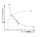
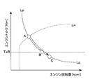
- the distribution of the engine torque Te and the motor torque Tm with respect to the required torque Tq changes with a change in the operating point of the internal combustion engine 3 defined by the engine speed and the engine torque.
- the operating point of the internal combustion engine 3 is controlled by the ECU 30 so as to move on the preset normal line La. This normal line La is determined in advance by a test using a simulation or an actual machine so that the fuel consumption of the internal combustion engine 3 is optimized and noise can be reduced.
- the ECU 30 In order to implement the lean combustion mode and the stoichiometric combustion mode, the ECU 30 measures the air-fuel ratio with reference to the output value of the A / F sensor 15, and the deviation between the measured air-fuel ratio and the target air-fuel ratio in the current operation mode is Feedback control is performed so as to decrease. Switching from the lean combustion mode to the stoichiometric combustion mode is performed in a short time by temporarily increasing the fuel injection amount in consideration of the response delay of the intake air amount. During a period in which the response of the intake air amount is delayed, the fuel increase is switched from the first target air-fuel ratio ⁇ 1 in the lean combustion mode to the target air-fuel ratio ⁇ 2 in the stoichiometric combustion mode.
- the fuel injection amount becomes ⁇ 1 / ⁇ 2 before and after switching of the air-fuel ratio, so the engine torque also becomes ⁇ 1 / ⁇ 2 times before and after switching of the air-fuel ratio.
- the engine torque is about 1.5 times before and after the air-fuel ratio is switched.
- This embodiment is characterized by the control performed by the ECU 30 when switching from the lean combustion mode to the stoichiometric combustion mode.
- a comparative example will be described for understanding the present control.
- the operation mode is switched from the lean combustion mode to the stoichiometric combustion mode at the operating point A shown in FIG. 2, the engine torque increases as described above.
- the distribution of the motor torque TmA and the engine torque TeA with respect to the required torque Tq is as illustrated.
- the second motor / generator 5 performs regenerative control in order to reduce the surplus torque.
- the regenerative torque TmA ′ of the second motor / generator 5 has a limit.
- the limit is the regenerative torque Tlim
- the regenerative torque Tlim is determined by various conditions such as the upper limit of the storage rate of the battery 26, the input limit of the battery 26, and the minimum torque of the second motor / generator 5. Varies depending on the conditions of the conditions. In the case of the comparative example of FIG.
- the following equation 1 may be satisfied before and after switching from the lean combustion mode to the stoichiometric combustion mode.
- Equation 2 is established for the engine torque before and after switching of the operation mode.
- TeB ' ⁇ 1 / ⁇ 2 * TeB 2
- the regenerative torque TmB ′ is equal to the regenerative torque Tlim, and Equation 3 is established.
- equation 4 is obtained.
- the engine torque TeB is calculated based on the equation (1), and the operating point of the internal combustion engine 3 is calculated up to the operating point of the engine torque TeB.
- the distribution of the engine torque with respect to the required torque is reduced by the movement, and then (2) air-fuel ratio switching control for reducing the air-fuel ratio is performed.
- the increase in engine torque can be completely absorbed by the regenerative control of the second motor / generator 5. That is, it is possible to avoid the generation of surplus torque accompanying the switching of the operation mode.
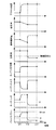
- the time change of each parameter of the vehicle 1 when this control is executed is as follows. As shown in FIG. 4, in a state where the internal combustion engine 3 is operated in the lean combustion mode, the accelerator pedal 28 is depressed by a driver at a time t11 exceeding a predetermined depression speed and exceeding a predetermined depression amount. In this case, it is determined that the operation mode of the internal combustion engine 3 should be switched from the lean combustion mode to the stoichiometric combustion mode because the output torque is insufficient. When such determination is made, an engine torque for reducing the distribution of the engine torque with respect to the required torque is calculated based on the above-described equation 4.
- the operating point of the internal combustion engine 3 is moved from the operating point at time t11 along the equal power line Lp (FIG. 2), that is, to the operating point of the engine torque calculated based on Expression 4 while maintaining the engine power. . Since the operating point of the internal combustion engine 3 is moved along the equal power line Lp, the engine speed changes to the high speed side and the engine torque changes to the low torque side from time t11. As the operating point changes, the intake air amount and the fuel injection amount decrease. On the other hand, the motor torque increases so as to balance with a decrease in the distribution of the engine torque with respect to the required torque. Since the power consumption increases due to the increase of the motor torque, the battery input / output (battery power) increases within the range of the output limit Wout.
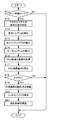
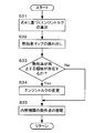
- control routine executed by the ECU 30 to realize the above-described control will be described with reference to FIG.
- the program of the control routine of FIG. 5 is held in the ECU 30, and is read out in a timely manner and repeatedly executed at predetermined intervals.
- step S1 the ECU 30 determines whether or not the operation mode is the lean combustion mode. If it is in the lean combustion mode, the process proceeds to step S2. If not, the subsequent process is skipped and the current routine is terminated.
- step S ⁇ b> 2 the ECU 30 refers to the signal of the accelerator opening sensor 31 and acquires the operation state of the accelerator pedal 28. The ECU 30 acquires the depression speed and the depression amount of the accelerator pedal 28 as the operation state of the accelerator pedal 28, respectively.
- step S3 the ECU 30 calculates the required torque Tq based on the depression amount (accelerator opening) of the accelerator pedal 28 acquired in step S2 and the vehicle speed obtained from the vehicle speed sensor 32.
- the required torque Tq is calculated based on a calculation map prepared in advance and held in the ECU 30.
- step S4 the ECU 30 calculates the engine torque Te.
- the engine torque Te is calculated based on the above-described normal line La (FIG. 2) and the engine speed.
- step S5 the ECU 30 calculates the motor torque Tm based on the required torque Tq and the engine torque Te. Thereby, the distribution of the engine torque Te and the motor torque Tm with respect to the required torque Tq is determined.
- step S6 the ECU 30 determines whether or not the operation mode of the internal combustion engine 3 should be switched from the lean combustion mode to the stoichiometric combustion mode based on the success or failure of the mode switching condition.
- the mode switching condition is set based on the operation state of the accelerator pedal 28 acquired in step S2. Specifically, the mode switching condition is satisfied when the depression speed of the accelerator pedal 28 exceeds a predetermined value and the depression amount exceeds a predetermined value. When the mode switching condition is satisfied, it is determined that the operation mode should be switched. If the mode switching condition is satisfied, the process proceeds to step S7. If the mode switching condition is not satisfied, the subsequent processing is skipped and the current routine is terminated.
- step S7 the ECU 30 moves the operating point of the internal combustion engine 3 to the low torque side. Since the internal combustion engine 3 is connected to the first motor / generator 4 via the power split mechanism 6 and can be differentially rotated, the ECU 30 controls the torque of the first motor / generator 4 to thereby control the internal combustion engine 3. Move the operating point.
- the ECU 30 calculates the regenerative torque Tlim from the above-described conditions such as the storage rate of the battery 26, and calculates the engine torque based on the above-described equation 4. Then, the ECU 30 moves the operating point of the internal combustion engine 3 along the equal power line Lp (see FIG. 2) until the calculated engine torque is reached. Thereby, the distribution of the engine torque with respect to the required torque decreases.
- the ECU 30 In parallel with the movement of the operating point of the internal combustion engine 3, the ECU 30 increases the motor torque of the second motor / generator 5 so as to balance with the decrease in the distribution of the engine torque with respect to the required torque.
- the ECU 30 functions as torque control means according to the present invention by executing this step S7.
- step S8 the ECU 30 performs air-fuel ratio switching control for increasing the fuel injection amount of the internal combustion engine 3 and lowering the air-fuel ratio.
- the ECU 30 functions as air-fuel ratio control means according to the present invention by executing step S8.
- step S9 the ECU 30 performs regenerative control of the second motor / generator 5 in order to absorb engine torque that has been increased by the air-fuel ratio switching control and exceeded the required torque. This regenerative control is performed with a regenerative torque that limits the regenerative torque Tlim.
- step S7 since the operating point of the internal combustion engine 3 is moved along the equal power line Lp, the engine power can be maintained during the movement of the operating point. Therefore, it is possible to avoid excess or deficiency of the power of the internal combustion engine 3 during movement of the operating point.
- FIG. 1 is referred to regarding the physical configuration of the vehicle 1.
- the ECU 30 distributes the engine torque to the required torque in the same manner as in the first embodiment in accordance with the rich spike for purifying the nitrogen oxides stored in the NOx catalyst 16 during the lean combustion mode. It is to reduce.
- the ECU 30 Decides that a rich spike should be implemented. Since the rich spike temporarily changes the air-fuel ratio to the rich-side air-fuel ratio during the lean combustion mode, the rich spike corresponds to the non-lean combustion mode. Therefore, when the NOx occlusion amount reaches the predetermined value St at which the rich spike should be performed, this corresponds to a case where the operation mode of the internal combustion engine 3 should be switched from the lean combustion mode to the non-lean combustion mode.
- the predetermined value St is set to a small value with a certain margin than the storage limit value Sm of the NOx catalyst 16.
- the ECU 30 calculates the engine torque for reducing the distribution of the engine torque with respect to the required torque based on the above-described equation 4.
- the target air-fuel ratio ⁇ 3 at the time of rich spike (where ⁇ 2> ⁇ 3 is used) is used in Equation 4 instead of the target air-fuel ratio ⁇ 2 in the stoichiometric combustion mode.
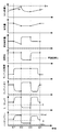
- the operating point of the internal combustion engine 3 is moved from the operating point at time t21 to the operating point of the engine torque calculated based on Expression 4 along the equal power line Lp (FIG. 2).
- the engine speed changes to the high speed side and the engine torque changes to the low torque side from time t21.
- the intake air amount and the fuel injection amount decrease.
- the motor torque increases so as to balance with a decrease in the distribution of the engine torque with respect to the required torque. Since the power consumption increases due to the increase of the motor torque, the battery input / output (battery power) increases within the range of the output limit Wout.
- Step S11 to S15 are the same as steps S1 to S5 of the control routine of the first embodiment (FIG. 5). That is, in step S11, the ECU 30 determines whether or not the operation mode is the lean combustion mode. If it is in the lean combustion mode, the process proceeds to step S12. If not, the subsequent process is skipped and the current routine is terminated.
- step S ⁇ b> 12 the ECU 30 refers to the signal from the accelerator opening sensor 31 and acquires the operation state of the accelerator pedal 28.
- step S13 the ECU 30 calculates the required torque Tq based on the accelerator opening and the vehicle speed.
- step S14 the ECU 30 calculates the engine torque Te.
- step S15 the ECU 30 calculates a motor torque Tm based on the required torque Tq and the engine torque Te. Thereby, the distribution of the engine torque Te and the motor torque Tm with respect to the required torque Tq is determined.
- step S16 the ECU 30 refers to the signal from the temperature sensor 18 and acquires the temperature of the NOx catalyst 16.
- the ECU 30 estimates the NOx occlusion amount S of the NOx catalyst 16.
- the estimation of the NOx occlusion amount S can be realized by a known or publicly known method. For example, the ECU 30 calculates the total exhaust flow rate during the period in which the lean combustion mode is performed after the rich spike is performed, and estimates the NOx occlusion amount based on the total flow rate and the temperature of the NOx catalyst 16 acquired in step S16. .
- step S18 the ECU 30 determines whether or not the NOx occlusion amount S has reached the predetermined value St at which the rich spike described above is to be performed, that is, whether or not the NOx occlusion amount S is equal to or greater than the predetermined value St. If the NOx occlusion amount S has reached the predetermined value St, the process proceeds to step S19. If not, the subsequent process is skipped and the current routine is terminated.
- step S 19 the ECU 30 moves the operating point of the internal combustion engine 3 by performing torque control of the first motor / generator 4.
- the ECU 30 calculates the regenerative torque Tlim from the above-described various conditions such as the storage rate of the battery 26, and calculates the engine torque based on the above-described equation 4. Then, the operating point of the internal combustion engine 3 is moved along the equal power line Lp (see FIG. 2) until the calculated engine torque is reached. Thereby, the distribution of the engine torque with respect to the required torque decreases.
- the ECU 30 increases the motor torque of the second motor / generator 5 so as to balance with the decrease in the distribution of the engine torque with respect to the required torque.
- the ECU 30 functions as torque control means according to the present invention by executing this step S19.
- step S20 the ECU 30 performs rich spike as air-fuel ratio switching control.
- the ECU 30 functions as air-fuel ratio control means according to the present invention by executing step S20.
- step S ⁇ b> 21 the ECU 30 performs regenerative control of the second motor / generator 5 in order to absorb engine torque that increases due to a rich spike and exceeds the required torque. This regenerative control is performed with a regenerative torque that limits the regenerative torque Tlim.
- step S19 since the operating point of the internal combustion engine 3 is moved along the equal power line Lp, the engine power can be maintained during the movement of the operating point. Therefore, it is possible to avoid excess or deficiency of the power of the internal combustion engine 3 during movement of the operating point.
- the control in the second form can be performed together with the control in the first form. In this case, the shock of the vehicle 1 can be suppressed at the time of switching from the lean combustion mode to the stoichiometric combustion mode and at the time of rich spike.
- step S7 of FIG. 5 or step S19 of FIG. 7 the engine torque is calculated based on the above equation 4, and the operating point of the internal combustion engine 3 is moved to the operating point of the engine torque.
- the thermal efficiency is improved to a lower torque side than the operating point B of the engine torque calculated based on the above equation 4.
- the operating point of the internal combustion engine 3 is moved to the operating point C having the same power and the highest thermal efficiency.
- the control routine of FIG. 9 is incorporated in step S7 of FIG. 5 or step S19 of FIG. 7, and is implemented as a subroutine of the control routine of FIG. 5 or FIG.
- the ECU 30 functions as a torque changing unit according to the present invention.
- step S31 the ECU 30 calculates the engine torque based on the above-described equation 4.
- step S32 the ECU 30 reads a thermal efficiency map in which the operating point of the internal combustion engine 3 is associated with the thermal efficiency.
- step S33 the ECU 30 refers to the thermal efficiency map read in step S32, and determines whether or not there is a region where the thermal efficiency of the internal combustion engine 3 is improved on the lower torque side than the operating point of the engine torque calculated in step S31. To do. If there is an area, the process proceeds to step S34; otherwise, the process skips step S34 and proceeds to step S35.
- step S34 the ECU 30 changes the engine torque to the low torque side.
- the engine torque is changed to the engine torque at the maximum thermal efficiency operating point among the operating points on the low torque side having the same power and high thermal efficiency as the operating point of the engine torque calculated in step S31. That is, when there is an operating point that gives such maximum thermal efficiency, the engine torque calculated in step S31 is changed to a small value.
- step S35 the ECU 30 controls the torque of the first motor / generator 4 to move the operating point of the internal combustion engine 3. That is, the operating point of the internal combustion engine 3 is moved along the equal power line Lp (see FIG. 2) until the engine torque calculated in step S31 or the changed engine torque changed in step S34 is reached. Thereby, the distribution of the engine torque with respect to the required torque decreases.
- the ECU 30 increases the motor torque of the second motor / generator 5 so as to balance with the decrease in the distribution of the engine torque with respect to the required torque.
- the present invention is not limited to the above embodiments, and can be implemented in various forms within the scope of the gist of the present invention.
- Each of the above modes maintains the engine torque at the same power when switching from the lean combustion mode to the stoichiometric combustion mode or when rich spike is to be performed, that is, when the operation mode is to be switched from the lean combustion mode to the non-lean combustion mode.
- it is not essential to maintain the same power when changing the engine torque to the low torque side.
- the present invention can be implemented in a form in which the engine speed is changed and the engine torque is changed to the low torque side. Even in this configuration, an increase in engine torque accompanying the execution of the air-fuel ratio switching control can be suppressed, so that a vehicle shock can be suppressed.
- the engine torque is calculated based on the above formula 4 and the distribution of the engine torque with respect to the required torque is reduced, so that the excess amount where the engine torque exceeds the required torque matches the regenerative torque. (See FIG. 3).
- production of the surplus torque can be avoided without waste.
- the rate of decrease in the distribution of the engine torque relative to the required torque may be set as appropriate.
- the present invention can be implemented in a form in which the distribution of the engine torque with respect to the required torque is reduced at a constant reduction rate. Even in this configuration, generation of surplus torque can be completely avoided if the excess amount of engine torque is smaller than the regenerative torque. Further, even when the excess amount is larger than the regenerative torque and the surplus torque is generated, the surplus torque can be reduced as compared with the case where the distribution of the engine torque is not lowered, so that the shock of the vehicle can be suppressed.
- Each of the above embodiments is a control device applied to a hybrid vehicle including a first motor / generator and a second motor / generator.
- a control device applied to a hybrid vehicle including a first motor / generator and a second motor / generator.
- an output gear such as an output gear to which engine torque is transmitted or an output member such as an output shaft is used.
- the control device of the present invention can be applied to a hybrid in which one motor / generator is connected.
Landscapes
- Engineering & Computer Science (AREA)
- Mechanical Engineering (AREA)
- Transportation (AREA)
- Chemical & Material Sciences (AREA)
- Combustion & Propulsion (AREA)
- Automation & Control Theory (AREA)
- Electric Propulsion And Braking For Vehicles (AREA)
- Hybrid Electric Vehicles (AREA)
- Control Of Vehicle Engines Or Engines For Specific Uses (AREA)
- Electrical Control Of Air Or Fuel Supplied To Internal-Combustion Engine (AREA)
- General Engineering & Computer Science (AREA)
Abstract
Description
図1に示すように、車両1は複数の動力源を組み合わせたハイブリッド車両として構成されている。車両1は、内燃機関3と、2つのモータ・ジェネレータ4、5とを走行用の動力源として備えている。内燃機関3は4つの気筒10を備えた直列4気筒型の内燃機関である。内燃機関3はいわゆるリーンバーンエンジンとして構成されていて、リーン燃焼モードとストイキ燃焼モードとの間で運転モードを切り替えることができる。リーン燃焼モードは、理論空燃比よりもリーン側に設定された空燃比を目標とするリーン燃焼を実施する運転モードである。ストイキ燃焼モードは、リーン燃焼モードの空燃比よりもリッチ側の理論空燃比又はその近辺の空燃比を目標とするストイキ燃焼を実施する運転モードである。ストイキ燃焼モードはリーン燃焼モードの空燃比よりもリッチ側の空燃比を目標空燃比とするものであるから本発明に係る非リーン燃焼モードに相当する。
次に、本発明の第2の形態を図6及び図7を参照しながら説明する。第2の形態はECU30が実施する制御を除き第1の形態と同一である。車両1の物理的構成については図1が参照される。本形態においては、リーン燃焼モードの実施中にNOx触媒16に吸蔵された窒素酸化物を浄化するためのリッチスパイクに合わせて、ECU30が第1の形態と同様に要求トルクに対するエンジントルクの配分を低下させるものである。
次に、図8及び図9を参照しながら本発明の第3の形態を説明する。第3の形態の制御は上述した第1又は第2の形態の制御と組み合わせて実施されるものである。第1又は第2の形態は、図5のステップS7又は図7のステップS19において、上記式4に基づいてエンジントルクを計算し、そのエンジントルクの動作点まで内燃機関3の動作点を移動させるものである。第3の形態は、リーン燃焼モードからストイキ燃焼モードへ切り替えるべき場合又はリッチスパイクを実施すべき場合に、上記式4に基づいて計算したエンジントルクの動作点Bよりも低トルク側に熱効率が向上する領域が存在する場合、等パワーでかつ熱効率が最大の動作点Cまで内燃機関3の動作点を移動させるものである。
Claims (6)
- リーン燃焼モードと、前記リーン燃焼モードよりもリッチ側の空燃比に設定された非リーン燃焼モードとの間で運転モードを切り替え可能な内燃機関と、少なくとも一つのモータ・ジェネレータとを走行用動力源として備えたハイブリッド車両に適用されるハイブリッド車両の制御装置において、
要求トルクに対する前記内燃機関のエンジントルクと前記モータ・ジェネレータのモータトルクとの配分を変更可能なトルク制御手段と、
前記運転モードを前記リーン燃焼モードから前記非リーン燃焼モードに切り替える場合に前記内燃機関の空燃比を低下させる空燃比切替制御を実施する空燃比制御手段と、を備え、
前記運転モードを前記リーン燃焼モードから前記非リーン燃焼モードに切り替えるべき場合、前記トルク制御手段が前記要求トルクに対する前記エンジントルクの配分を低下させてから前記空燃比制御手段が前記空燃比切替制御を実施するハイブリッド車両の制御装置。 - リーン燃焼モードを実施可能で、かつ前記リーン燃焼モードの実施中に空燃比を一時的にリッチ側の空燃比に変更するリッチスパイクを実施可能な内燃機関と、少なくとも一つのモータ・ジェネレータとを走行用動力源として備えたハイブリッド車両に適用されるハイブリッド車両の制御装置において、
要求トルクに対する前記内燃機関のエンジントルクと前記モータ・ジェネレータのモータトルクとの配分を変更可能なトルク制御手段と、
前記リッチスパイクを実施する場合に前記内燃機関の空燃比を低下させる空燃比切替制御を実施する空燃比制御手段と、を備え、
前記リッチスパイクを実施すべき場合、前記トルク制御手段が前記要求トルクに対する前記エンジントルクの配分を低下させてから前記空燃比制御手段が前記空燃比切替制御を実施するハイブリッド車両の制御装置。 - 前記トルク制御手段は、前記リーン燃焼モード時の第1目標空燃比、前記非リーン燃焼モード時の第2目標空燃比、前記要求トルク、及び前記モータ・ジェネレータにて回生可能な回生可能トルクに基づいて前記エンジントルクを算出することにより、前記要求トルクに対する前記エンジントルクの配分を低下させる請求項1の制御装置。
- 前記トルク制御手段は、前記リーン燃焼モード時の第1目標空燃比、前記リッチスパイク実施時の第2目標空燃比、前記要求トルク、及び前記モータ・ジェネレータにて回生可能な回生可能トルクに基づいて前記エンジントルクを算出することにより、前記要求トルクに対する前記エンジントルクの配分を低下させる請求項2の制御装置。
- 前記トルク制御手段が算出した前記エンジントルクよりも低トルク側に前記内燃機関の熱効率が向上する領域が存在する場合、当該エンジントルクを低い値に変更するトルク変更手段を更に備える請求項3又は4の制御装置。
- 前記トルク制御手段は、前記内燃機関が等パワーに維持された状態で前記要求トルクに対する前記エンジントルクの配分を低下させる請求項1~4のいずれか一項の制御装置。
Priority Applications (7)
| Application Number | Priority Date | Filing Date | Title |
|---|---|---|---|
| PCT/JP2013/065254 WO2014192151A1 (ja) | 2013-05-31 | 2013-05-31 | ハイブリッド車両の制御装置 |
| JP2015519589A JP5983873B2 (ja) | 2013-05-31 | 2013-05-31 | ハイブリッド車両の制御装置 |
| BR112015030085-5A BR112015030085B1 (pt) | 2013-05-31 | 2013-05-31 | Dispositivo de controle para veículo híbrido |
| US14/894,630 US9527497B2 (en) | 2013-05-31 | 2013-05-31 | Control device for hybrid vehicle |
| CN201380077028.9A CN105246748B (zh) | 2013-05-31 | 2013-05-31 | 混合动力车辆的控制装置 |
| KR1020157034089A KR101696766B1 (ko) | 2013-05-31 | 2013-05-31 | 하이브리드 차량의 제어 장치 |
| DE112013007119.3T DE112013007119B4 (de) | 2013-05-31 | 2013-05-31 | Steuervorrichtung für ein Hybridfahrzeug |
Applications Claiming Priority (1)
| Application Number | Priority Date | Filing Date | Title |
|---|---|---|---|
| PCT/JP2013/065254 WO2014192151A1 (ja) | 2013-05-31 | 2013-05-31 | ハイブリッド車両の制御装置 |
Publications (1)
| Publication Number | Publication Date |
|---|---|
| WO2014192151A1 true WO2014192151A1 (ja) | 2014-12-04 |
Family
ID=51988219
Family Applications (1)
| Application Number | Title | Priority Date | Filing Date |
|---|---|---|---|
| PCT/JP2013/065254 Ceased WO2014192151A1 (ja) | 2013-05-31 | 2013-05-31 | ハイブリッド車両の制御装置 |
Country Status (7)
| Country | Link |
|---|---|
| US (1) | US9527497B2 (ja) |
| JP (1) | JP5983873B2 (ja) |
| KR (1) | KR101696766B1 (ja) |
| CN (1) | CN105246748B (ja) |
| BR (1) | BR112015030085B1 (ja) |
| DE (1) | DE112013007119B4 (ja) |
| WO (1) | WO2014192151A1 (ja) |
Cited By (1)
| Publication number | Priority date | Publication date | Assignee | Title |
|---|---|---|---|---|
| CN107042820A (zh) * | 2015-12-28 | 2017-08-15 | 罗伯特·博世有限公司 | 混合动力系统中的扭矩储备 |
Families Citing this family (10)
| Publication number | Priority date | Publication date | Assignee | Title |
|---|---|---|---|---|
| JP6296228B2 (ja) * | 2013-12-13 | 2018-03-20 | 三菱自動車工業株式会社 | ハイブリッド車両の制御装置 |
| US10468759B2 (en) | 2015-05-22 | 2019-11-05 | Systems And Software Enterprises, Llc | Hybrid steerable avionic antenna |
| US10628492B2 (en) | 2017-07-20 | 2020-04-21 | Microsoft Technology Licensing, Llc | Distributed graph database writes |
| WO2019073561A1 (ja) * | 2017-10-12 | 2019-04-18 | 日産自動車株式会社 | ハイブリッド車両の制御方法および制御装置 |
| RU2748924C1 (ru) * | 2017-12-15 | 2021-06-01 | Ниссан Мотор Ко., Лтд. | Способ управления силовой установкой и силовая установка |
| CN108545075B (zh) * | 2018-04-02 | 2019-07-23 | 吉林大学 | 一种行星式混联混合动力系统分层优化控制方法 |
| DE102019213082A1 (de) * | 2019-08-30 | 2021-03-04 | Robert Bosch Gmbh | Verfahren zum Betreiben eines Hybridfahrzeugs |
| CN111169465B (zh) * | 2020-01-15 | 2021-06-11 | 上海电气集团股份有限公司 | 一种重度混合动力车辆运行的控制方法 |
| KR102250318B1 (ko) * | 2020-11-11 | 2021-05-11 | 비테스코 테크놀로지스 게엠베하 | 하이브리드 차량의 린번엔진 제어 장치 및 방법 |
| CN117751064A (zh) * | 2021-08-04 | 2024-03-22 | 日产自动车株式会社 | 混合动力车辆的控制方法以及混合动力车辆的控制装置 |
Citations (2)
| Publication number | Priority date | Publication date | Assignee | Title |
|---|---|---|---|---|
| JP2006248519A (ja) * | 1998-03-19 | 2006-09-21 | Hitachi Ltd | ハイブリッド自動車 |
| JP2008068802A (ja) * | 2006-09-15 | 2008-03-27 | Toyota Motor Corp | ハイブリッド車両 |
Family Cites Families (9)
| Publication number | Priority date | Publication date | Assignee | Title |
|---|---|---|---|---|
| JPH0629A (ja) | 1992-06-17 | 1994-01-11 | Yohei Yamashita | 植物の栽培方法 |
| DE19852600A1 (de) | 1998-11-14 | 2000-05-18 | Bosch Gmbh Robert | Verfahren zum Betreiben einer Brennkraftmaschine insbesondere eines Kraftfahrzeugs |
| JP2005069029A (ja) | 2003-08-27 | 2005-03-17 | Toyota Motor Corp | 内燃機関の制御装置 |
| JP3783712B2 (ja) | 2003-12-03 | 2006-06-07 | トヨタ自動車株式会社 | ハイブリッド車両における内燃機関の制御方法 |
| US7401462B2 (en) | 2004-03-30 | 2008-07-22 | General Motors Corporation | Control strategy for lean NOx trap regeneration |
| JP2006177306A (ja) * | 2004-12-24 | 2006-07-06 | Toyota Motor Corp | ハイブリッド車両の内燃機関制御装置 |
| DE102005003628A1 (de) | 2005-01-26 | 2006-08-03 | Robert Bosch Gmbh | Verfahren zum Betreiben eines Antriebsstrangs mit einer Elektromaschine und Vorrichtung zur Durchführung des Verfahrens |
| JP4301197B2 (ja) * | 2005-04-22 | 2009-07-22 | トヨタ自動車株式会社 | 車両の制御装置 |
| DE102011112343B4 (de) | 2011-09-03 | 2023-02-02 | Volkswagen Aktiengesellschaft | Verfahren und Vorrichtung zur Regeneration eines Filters eines Fahrzeugs |
-
2013
- 2013-05-31 DE DE112013007119.3T patent/DE112013007119B4/de active Active
- 2013-05-31 US US14/894,630 patent/US9527497B2/en active Active
- 2013-05-31 KR KR1020157034089A patent/KR101696766B1/ko active Active
- 2013-05-31 BR BR112015030085-5A patent/BR112015030085B1/pt active IP Right Grant
- 2013-05-31 WO PCT/JP2013/065254 patent/WO2014192151A1/ja not_active Ceased
- 2013-05-31 JP JP2015519589A patent/JP5983873B2/ja active Active
- 2013-05-31 CN CN201380077028.9A patent/CN105246748B/zh active Active
Patent Citations (2)
| Publication number | Priority date | Publication date | Assignee | Title |
|---|---|---|---|---|
| JP2006248519A (ja) * | 1998-03-19 | 2006-09-21 | Hitachi Ltd | ハイブリッド自動車 |
| JP2008068802A (ja) * | 2006-09-15 | 2008-03-27 | Toyota Motor Corp | ハイブリッド車両 |
Cited By (2)
| Publication number | Priority date | Publication date | Assignee | Title |
|---|---|---|---|---|
| CN107042820A (zh) * | 2015-12-28 | 2017-08-15 | 罗伯特·博世有限公司 | 混合动力系统中的扭矩储备 |
| CN107042820B (zh) * | 2015-12-28 | 2021-09-07 | 罗伯特·博世有限公司 | 混合动力系统中的扭矩储备 |
Also Published As
| Publication number | Publication date |
|---|---|
| KR20160008216A (ko) | 2016-01-21 |
| US9527497B2 (en) | 2016-12-27 |
| BR112015030085B1 (pt) | 2021-08-24 |
| BR112015030085A2 (pt) | 2017-07-25 |
| CN105246748B (zh) | 2017-07-28 |
| JP5983873B2 (ja) | 2016-09-06 |
| JPWO2014192151A1 (ja) | 2017-02-23 |
| CN105246748A (zh) | 2016-01-13 |
| KR101696766B1 (ko) | 2017-01-16 |
| DE112013007119B4 (de) | 2024-08-22 |
| DE112013007119T5 (de) | 2016-03-10 |
| US20160107636A1 (en) | 2016-04-21 |
Similar Documents
| Publication | Publication Date | Title |
|---|---|---|
| JP5983873B2 (ja) | ハイブリッド車両の制御装置 | |
| JP5861745B2 (ja) | 内燃機関の制御装置 | |
| JP5943097B2 (ja) | ハイブリッド車両の制御装置 | |
| JP5987918B2 (ja) | ハイブリッド車両の制御装置 | |
| US9180870B2 (en) | Diesel engine aftertreatment heating and cleaning hybrid operation | |
| KR101733078B1 (ko) | 하이브리드 차량의 제어 시스템 | |
| CN104968548B (zh) | 混合动力车辆的控制装置 | |
| US9764730B2 (en) | Vehicle control apparatus | |
| JP2012158303A (ja) | ハイブリッド自動車 | |
| JP5494398B2 (ja) | ハイブリッド自動車 | |
| JP2018134929A (ja) | ハイブリッド車両の制御装置 | |
| JP2015058786A (ja) | ハイブリッド車両の制御装置 | |
| JP4682906B2 (ja) | 内燃機関の制御装置 | |
| US9216725B2 (en) | Control apparatus for hybrid vehicle | |
| JP2017074911A (ja) | ハイブリッド車の制御装置 | |
| JP7718125B2 (ja) | ハイブリッド車両の制御装置 | |
| JP2017082619A (ja) | 車両 | |
| JP2016112975A (ja) | ハイブリッド車両の出力制御装置 | |
| JP2014151668A (ja) | ハイブリッド車両の制御装置 |
Legal Events
| Date | Code | Title | Description |
|---|---|---|---|
| 121 | Ep: the epo has been informed by wipo that ep was designated in this application |
Ref document number: 13885787 Country of ref document: EP Kind code of ref document: A1 |
|
| ENP | Entry into the national phase |
Ref document number: 2015519589 Country of ref document: JP Kind code of ref document: A |
|
| ENP | Entry into the national phase |
Ref document number: 20157034089 Country of ref document: KR Kind code of ref document: A |
|
| WWE | Wipo information: entry into national phase |
Ref document number: 14894630 Country of ref document: US Ref document number: 112013007119 Country of ref document: DE |
|
| REG | Reference to national code |
Ref country code: BR Ref legal event code: B01A Ref document number: 112015030085 Country of ref document: BR |
|
| 122 | Ep: pct application non-entry in european phase |
Ref document number: 13885787 Country of ref document: EP Kind code of ref document: A1 |
|
| ENP | Entry into the national phase |
Ref document number: 112015030085 Country of ref document: BR Kind code of ref document: A2 Effective date: 20151130 |