WO2014189031A1 - 貯蔵タンクの施工方法 - Google Patents
貯蔵タンクの施工方法 Download PDFInfo
- Publication number
- WO2014189031A1 WO2014189031A1 PCT/JP2014/063299 JP2014063299W WO2014189031A1 WO 2014189031 A1 WO2014189031 A1 WO 2014189031A1 JP 2014063299 W JP2014063299 W JP 2014063299W WO 2014189031 A1 WO2014189031 A1 WO 2014189031A1
- Authority
- WO
- WIPO (PCT)
- Prior art keywords
- precast concrete
- temporary opening
- opening
- wall surface
- storage tank
- Prior art date
- Legal status (The legal status is an assumption and is not a legal conclusion. Google has not performed a legal analysis and makes no representation as to the accuracy of the status listed.)
- Ceased
Links
Images





Classifications
-
- E—FIXED CONSTRUCTIONS
- E04—BUILDING
- E04H—BUILDINGS OR LIKE STRUCTURES FOR PARTICULAR PURPOSES; SWIMMING OR SPLASH BATHS OR POOLS; MASTS; FENCING; TENTS OR CANOPIES, IN GENERAL
- E04H7/00—Construction or assembling of bulk storage containers employing civil engineering techniques in situ or off the site
- E04H7/02—Containers for fluids or gases; Supports therefor
- E04H7/18—Containers for fluids or gases; Supports therefor mainly of concrete, e.g. reinforced concrete, or other stone-like material
- E04H7/20—Prestressed constructions
-
- E—FIXED CONSTRUCTIONS
- E04—BUILDING
- E04B—GENERAL BUILDING CONSTRUCTIONS; WALLS, e.g. PARTITIONS; ROOFS; FLOORS; CEILINGS; INSULATION OR OTHER PROTECTION OF BUILDINGS
- E04B1/00—Constructions in general; Structures which are not restricted either to walls, e.g. partitions, or floors or ceilings or roofs
- E04B1/16—Structures made from masses, e.g. of concrete, cast or similarly formed in situ with or without making use of additional elements, such as permanent forms, substructures to be coated with load-bearing material
- E04B1/167—Structures made from masses, e.g. of concrete, cast or similarly formed in situ with or without making use of additional elements, such as permanent forms, substructures to be coated with load-bearing material with permanent forms made of particular materials, e.g. layered products
-
- E—FIXED CONSTRUCTIONS
- E04—BUILDING
- E04B—GENERAL BUILDING CONSTRUCTIONS; WALLS, e.g. PARTITIONS; ROOFS; FLOORS; CEILINGS; INSULATION OR OTHER PROTECTION OF BUILDINGS
- E04B2/00—Walls, e.g. partitions, for buildings; Wall construction with regard to insulation; Connections specially adapted to walls
- E04B2/84—Walls made by casting, pouring, or tamping in situ
- E04B2/86—Walls made by casting, pouring, or tamping in situ made in permanent forms
- E04B2/8635—Walls made by casting, pouring, or tamping in situ made in permanent forms with ties attached to the inner faces of the forms
-
- E—FIXED CONSTRUCTIONS
- E04—BUILDING
- E04H—BUILDINGS OR LIKE STRUCTURES FOR PARTICULAR PURPOSES; SWIMMING OR SPLASH BATHS OR POOLS; MASTS; FENCING; TENTS OR CANOPIES, IN GENERAL
- E04H7/00—Construction or assembling of bulk storage containers employing civil engineering techniques in situ or off the site
- E04H7/02—Containers for fluids or gases; Supports therefor
- E04H7/18—Containers for fluids or gases; Supports therefor mainly of concrete, e.g. reinforced concrete, or other stone-like material
-
- E—FIXED CONSTRUCTIONS
- E04—BUILDING
- E04B—GENERAL BUILDING CONSTRUCTIONS; WALLS, e.g. PARTITIONS; ROOFS; FLOORS; CEILINGS; INSULATION OR OTHER PROTECTION OF BUILDINGS
- E04B2103/00—Material constitution of slabs, sheets or the like
- E04B2103/02—Material constitution of slabs, sheets or the like of ceramics, concrete or other stone-like material
-
- E—FIXED CONSTRUCTIONS
- E04—BUILDING
- E04H—BUILDINGS OR LIKE STRUCTURES FOR PARTICULAR PURPOSES; SWIMMING OR SPLASH BATHS OR POOLS; MASTS; FENCING; TENTS OR CANOPIES, IN GENERAL
- E04H7/00—Construction or assembling of bulk storage containers employing civil engineering techniques in situ or off the site
- E04H7/02—Containers for fluids or gases; Supports therefor
- E04H7/04—Containers for fluids or gases; Supports therefor mainly of metal
- E04H7/06—Containers for fluids or gases; Supports therefor mainly of metal with vertical axis
Definitions
- the present invention relates to a storage tank construction method.
- This application claims priority based on Japanese Patent Application No. 2013-106465 for which it applied to Japan on May 20, 2013, and uses the content here.
- a temporary opening for carrying construction materials and the like into the side wall is formed.
- Such a temporary opening is blocked by concrete cast in place when the construction of the above-ground storage tank is completed.
- the temporary openings are closed by assembling molds on the inner surface side and outer surface side of the side wall portion with respect to the temporary openings, and then placing concrete between the mold frames.
- the said temporary opening may be temporarily obstruct
- the closing plate is temporarily welded and fixed to a temporary member embedded in a frame shape around the temporary opening in advance, or the closing plate is attached using a reinforcing bar protruding into the temporary opening.
- the present invention has been made in view of the above circumstances, and the object of the present invention is to facilitate the process of closing the temporary opening to shorten the construction period, and to further improve accuracy by facilitating accuracy management.
- the object is to provide a storage tank construction method that has been made possible.
- the first aspect of the present invention is a storage tank construction method, in which a side wall portion is formed in a state in which a temporary opening is provided, and a precast concrete plate is provided on each of an inner wall surface side and an outer wall surface side of the temporary opening. And closing the inner wall surface side and the outer wall surface side of the temporary opening, using the precast concrete plate as a mold, placing concrete between these precast concrete plates, and closing the temporary opening And a step of performing.
- a metal plate is pasted in advance on a surface which is an inner side of the precast concrete plate.
- a third aspect of the present invention is the storage tank construction method according to the first or second aspect, wherein the precast concrete plate is fitted to the inner wall surface side and the outer wall surface side of the temporary opening, respectively. Then, a separator is attached between the precast concrete plates to maintain a constant interval between the precast concrete plates, and then the concrete is placed between the precast concrete plates.
- a precast concrete board is used as a formwork, concrete is placed between these precast concrete boards, and the temporary opening is closed. Therefore, the conventional work such as installation of the formwork and removal of the formwork becomes unnecessary, and the time required for these work can be eliminated. As a result, the construction period can be remarkably shortened as compared with the prior art.
- precast concrete plates are fitted on the inner wall surface side and outer wall surface side of the temporary opening to close the inner wall surface side and outer wall surface side of the temporary opening, respectively, and then concrete is placed between these precast concrete plates. Close the temporary opening. Therefore, as compared with the conventional case where the entire interior of the temporary opening is formed of on-site concrete, accuracy management becomes easier and the accuracy of the closed portion of the temporary opening can be improved.
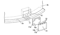
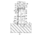
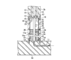
- FIG. 1 It is a figure which shows an example of the storage tank which concerns on this invention, and is a sectional side view of a storage tank. It is a perspective view of the side wall part of the outer tank of the storage tank which concerns on this invention. It is a perspective view which shows the periphery of temporary opening for demonstrating the process of the construction method of this invention. It is a sectional side view which shows the periphery of temporary opening for demonstrating the process of the construction method of this invention. It is a perspective view which shows schematic structure of a precast concrete board. It is a perspective view which shows the periphery of temporary opening for demonstrating the process of the construction method of this invention.
- FIG. 1A denotes a ground type low temperature tank (hereinafter referred to as a low temperature tank) as a storage tank according to the present invention.
- this low-temperature tank 1 is for storing a low-temperature liquefied gas such as LNG (Liquefied Natural Gas), and includes a metal inner tank 2 and a concrete outer tank 3. Yes.
- the inner tank 2 is a metal container that directly stores liquefied gas, and includes a bottom 2a, a side wall 2b, and a roof 2c.
- the outer tub 3 is a concrete container that surrounds and accommodates the inner tub 2. As shown in FIGS. 1A and 1B, the outer tub 3 includes a bottom 3a, a side wall 3b, and a roof 3c.
- a gap is formed between the inner tub 2 and the outer tub 3, and a cold insulation material, a liner, and the like are accommodated in the gap.
- the temporary opening 10 is formed in substantially the same manner as in the prior art.
- the temporary opening 10 is, for example, a rectangular opening having a width of about 5000 mm and a height of about 3000 mm, and is formed so as to be in contact with the upper surface of the bottom portion 3a at the lower end portion of the side wall portion 3b. That is, the temporary opening 10 is an opening formed in a rectangular shape between the side wall part 3b and the bottom part 3a by partially notching the lower end part of the side wall part 3b.
- a rectangular opening may be formed directly at the lower end of the side wall 3b and this may be used as the temporary opening 10.
- Two such temporary openings 10 are usually formed in one low-temperature tank 1, but may be one or three or more.
- the L-shaped pipe 11 when forming the bottom portion 3a, is embedded in a portion of the bottom portion 3a immediately below the temporary opening 10.
- the pipe 11 is arranged so that the opening on one end faces the outer peripheral surface of the bottom 3 a and the opening on the other end faces the upper surface of the bottom 3 a, that is, the temporary opening 10.
- the opening on the other end side of the pipe 11 is disposed at a substantially central portion in the thickness direction of the temporary opening 10 (direction passing through the temporary opening) as shown in FIG. 2B.
- the number of pipes 11 is not particularly limited, in the present embodiment, three pipes 11 are embedded at equal intervals in the circumferential direction of the side wall 3b as shown in FIG. 2A. However, it may be 2 or less or 4 or more.
- a connecting fitting 12 is embedded in a portion of the bottom portion 3a that is directly below the temporary opening 10.
- the connecting fitting 12 is embedded in the vicinity of the inner opening (opening on the inner wall surface of the side wall 3b) of the temporary opening 10 and in the vicinity of the outer opening (opening on the outer wall surface of the side wall 3b).
- the connection metal fitting 12 is each embed
- the connecting metal fitting 12 is made of, for example, an angle member in which a hole is formed and a bolt passed through the hole of the angle member.
- the bolt is attached to the angle member so as to be able to appear and move between the bottom 3a and the temporary opening 10.
- the bolt of the connecting metal 12 is connected to a connecting metal 19 (angle material) embedded in precast concrete plates 17a and 17b, which will be described later, and fastened with a nut or the like, whereby the angle material of the connecting metal 12 and the angle of the connecting metal 19 The material can be connected and fixed.
- the connecting metal fitting 12 is embedded at a position facing the temporary opening 10 in the side wall 3b, that is, at the lower end thereof. Similarly to the bottom 3a side, the connecting fitting 12 is embedded in the vicinity of the inner opening of the temporary opening 10 (opening on the inner wall surface of the side wall 3b) and the vicinity of the outer opening (opening on the outer wall surface of the side wall 3b). Is done. Moreover, the connection metal fitting 12 is each embed
- a rectangular precast concrete plate which will be described later, can be easily placed on the inner wall surface side opening portion and the outer wall surface side opening portion of the temporary opening 10, respectively. Can be fixed.
- a rebar 13 and a sheath 14 for introducing prestress are embedded as in the conventional case.
- a coupler 15 for connecting a new reinforcing bar to the reinforcing bar 13 is attached to the reinforcing bar 13 at a position facing the temporary opening 10, that is, a position exposed at the inner peripheral surface (upper surface and side surface) of the temporary opening 10. It is done.
- a coupler 16 for connecting a new sheath is attached to the sheath 14.
- the couplers 15 and 16 conventionally known ones such as a type that is tightened with screws are used.
- a coupler 15 and a coupler for connecting the reinforcing bar and the sheath to the position exposed on the inner peripheral surface of the temporary opening 10 also to the reinforcing bar and the sheath embedded in the bottom 3a. 16 may be provided.
- the precast concrete board 17a, 17b After forming the bottom part 3a and the side wall part 3b in the state which provided the temporary opening 10, the precast concrete board 17a, 17b about 80 mm in thickness to the inner wall surface side and outer wall surface side of the temporary opening 10, respectively. Fit. As shown in FIG. 3, the precast concrete plates 17a and 17b are manufactured in advance according to the shape and dimensions of the temporary opening 10 in a factory or the like, and are transported to a construction site by a vehicle or the like for use.
- the shape of the metal plate 18a is a shape that avoids the position where the connection fitting 19 and the nut 20 are embedded in the precast concrete plate 17a so that the connection fitting 19 and the nut 20 described later can be exposed.
- the metal plate 18a has a shape in which corners (four corners) of a rectangle are cut out and a through hole is formed in the center.
- FIG. 3 shows a structure in which the connection fitting 19 is embedded only in the four corners, the connection fitting 19 may be embedded in other locations. In that case, the shape of the metal plate 18a is also changed so as to expose all the connecting fittings 19.
- a through hole 21 for inserting a separator 25 described later is formed at the center of the precast concrete plate 17b arranged on the outer wall surface side of the temporary opening 10.
- a rectangular metal plate 18b made of iron or the like is pasted in advance at almost the entire inner surface of the precast concrete plate 17b, that is, the surface opposite to the outer peripheral surface of the side wall 3b.
- the notch groove 22 is formed in the upper end part of the precast concrete board 17b.
- the cutout groove 22 is formed by cutting out from the front surface to the back surface of the precast concrete plate 17b.
- the number and size of the notch grooves 22 are not particularly limited, and may be an appropriate number and size. In the present embodiment, three notch grooves 22 are formed corresponding to the number of pipes 11.
- the metal plate 18b is affixed to the surface opposite to the surface on which the connection fitting 19 is exposed. Therefore, the corners of the metal plate 18b are not cut out.
- the metal plate 18b it is necessary to cut out a portion corresponding to the through hole 21 and a portion corresponding to the cutout groove 22. Therefore, a through hole is formed at the center of the metal plate 18b, and a cutout portion communicating with the cutout groove 22 is formed at the upper end portion of the metal plate 18b.
- the connecting bracket 19 is embedded in advance in the corners of the precast concrete plates 17a and 17b.
- the connecting fittings 19 are disposed on both sides of the lower end portion and the upper end portion of the precast concrete plates 17a and 17b, which are positioned to face the connecting fitting 12 embedded in the bottom portion 3a and the side wall portion 3b in the vertical direction.
- the connection fitting 19 is formed of an angle member having a hole.
- the connecting bracket 19 is exposed and embedded on the inner surface of the precast concrete plate 17a, that is, the surface facing outward of the side wall portion 3b.
- the connection fitting 19 is exposed and embedded in the outer surface of the precast concrete plate 17b, that is, the surface facing outward of the side wall portion 3b.
- a nut 20 screwed to one end side of a separator 25 described later is exposed at the center of the inner surface of the precast concrete plate 17a, and one surface of the nut 20 is exposed to the inner surface of the precast concrete plate 17a. And it is embed
- the precast concrete plate 17a on the inner wall surface side is fitted into the inner wall surface side in the temporary opening 10 as shown in FIG. 4A.
- the connection fittings 19 embedded in the precast concrete plate 17a are connected to the connection fittings 12 facing each other in the vertical direction. That is, the connecting bracket 19 embedded in the upper end portion of the precast concrete plate 17a is connected to the connecting bracket 12 embedded in the side wall portion 3b, and the connecting bracket 19 embedded in the lower end portion of the precast concrete plate 17a is connected to the bottom portion 3a. 12 is connected.
- the connection between the connection fittings 12 and 19 is performed by fitting the front end side of the bolt provided in the connection fitting 12 into the hole of the connection fitting 19 and screwing the nut.
- the inner peripheral surface (upper surface and side surface) of the temporary opening 10 that is, the coupler 15 of the reinforcing bar 13 exposed on the surface of the side wall 3 b on the temporary opening 10 side.
- Reinforcing bar 23 is connected to it.
- the reinforcing bar 23 is for integrating and strengthening the side wall 3b and the concrete that closes the temporary opening 10.
- the rebar 23 integrates the side wall 3b and the concrete closing the temporary opening 10. Arranged as the main purpose.
- the reinforcing bars 23 it is not necessary to arrange the reinforcing bars 23 from the top to the bottom in the temporary opening 10 or from the right to the left, and the reinforcing bars 23 may be arranged to extend to the side peripheral portion of the temporary opening 10. Therefore, the length of the reinforcing bar 23 is about several tens of centimeters.
- the reinforcing bar 23 is connected to the coupler 15 and disposed.
- the reinforcing bar 23 extends from the lower end of the side wall 3b into the temporary opening 10, but the reinforcing bar 23 extends into the temporary opening 10 from the side facing the temporary opening 10 of the side wall 3b. I am letting it out. Further, when the coupler 15 is embedded in the bottom portion 3a, the reinforcing bar 23 is extended into the temporary opening 10 also from the bottom portion 3a.
- a new sheath 24 is connected to the sheath 14 separately from the rebar 23. That is, the sheath 24 is connected to and communicated with the sheath 14 of the side wall portion 3b by the coupler 16.
- tension is applied to the sheath 14 and the sheath 24 through the PC steel wire, and grout is injected into the remaining space in the sheaths 14 and 24 to be integrated, thereby prestressing. Concrete can be completed.
- a new sheath 24 may be connected to a sheath (not shown) embedded in the bottom 3a. The sheath 24 is arranged not only in the vertical direction (vertical direction) but also in the horizontal direction (horizontal direction).
- a separator 25 made of a steel bar is attached to the nut 20 embedded in the center of the precast concrete plate 17a.
- Male screw portions are formed at both ends of the separator 25.
- the length of the separator 25 is slightly shorter than the thickness of the side wall 3b. As described later, the separator 25 having such a configuration can maintain a constant distance between the precast concrete plate 17a and the precast concrete plate 17b.
- the separator 25 is in a state in which the outer surface of the precast concrete plate 17a is flush with the inner wall surface of the side wall portion 3b and the outer surface of the precast concrete plate 17b is flush with the outer wall surface of the side wall portion 3b.
- the space between the precast concrete plates 17a and 17b is maintained at a constant interval.
- the precast concrete plate 17b on the outer wall surface side is fitted into the outer wall surface side in the temporary opening 10 as shown in FIG. 5A.
- the other end side of the separator 25 is inserted into the through hole 21 of the precast concrete plate 17b.
- buried under the precast concrete board 17b is connected with the connection metal fitting 12 respectively opposed to the up-down direction similarly to the case of the precast concrete board 17a.
- the precast concrete plate 17a is fitted on the inner wall surface side of the temporary opening 10 and the precast concrete plate 17b is fitted on the outer wall surface side of the temporary opening 10, and the side wall portion 3b and the bottom portion 3a are connected to each other via the connecting fittings 12 and 19.
- the inner wall surface side and the outer wall surface side of the temporary opening 10 can each be closed.
- the ready-mixed concrete 26 is placed between the precast concrete plates 17a and 17b as shown in FIG. 5B. That is, the ready-mixed concrete 26 is pumped from the opening on one end side facing the outer peripheral surface of the bottom 3a of the pipe 11 embedded in the bottom 3a. Then, in the temporary opening 10, the opening on the inner wall surface side and the opening on the outer wall surface side are respectively closed by the precast concrete plates 17 a and 17 b, so that the ready-mixed concrete 26 moves upward from the lower side in the temporary opening 10. It fills up.
- ready-mixed concrete 26 When the inside of the temporary opening 10 is filled with ready-mixed concrete, ready-mixed concrete 26 overflows from the notch groove 22 formed in the upper end portion of the precast concrete plate 17b on the outer wall surface side shown in FIG. 5A. When the ready-mixed concrete 26 overflowing from the notch groove 22 is thus confirmed, the pumping of the ready-mixed concrete 26 is stopped and the opening on one end side of the pipe 11 is covered. Thereby, the placement of the ready-mixed concrete 26 between the precast concrete plates 17a and 17b in the temporary opening 10 is completed, and the temporary opening 10 can be filled with the ready-mixed concrete 26.
- a slight gap is formed between the precast concrete plates 17a and 17b and the bottom 3a and the side wall 3b, that is, at the joint. From such joints, the ready-mixed concrete 26 leaks slightly with the placement (pumping) of the ready-mixed concrete 26. However, unlike the liquid, the ready-mixed concrete 26 does not have high fluidity and hardens as time passes. Therefore, the leaked ready-mixed concrete 26 hardens in a state where the gaps in the joints are closed. Therefore, the gap between the joints is filled and closed without performing joint processing.
- the temporary opening 10 is closed by the precast concrete plates 17a and 17b and the concrete placed therebetween, and then the PC steel wire is inserted into the sheaths 14 and 24 in the same manner as in the past to give tension.
- closes the side wall part 3b and the temporary opening 10 is prestressed concrete by inject
- the roof 3c and the like are formed as in the conventional case, and the low temperature tank 1 shown in FIGS. 1A and 1B is completed.
- the precast concrete plates 17 a and 17 b are used as a mold, the ready-mixed concrete 26 is placed (pumped) between the precast concrete plates 17 a and 17 b, and the temporary opening 10 is closed. Therefore, the conventional work such as installation of the formwork and removal of the formwork becomes unnecessary. Therefore, by eliminating the time required for these operations, the construction period can be significantly shortened compared to the conventional method. In particular, since the work inside the low temperature tank 1 such as removal of the mold placed on the inner wall surface side of the side wall 3b is unnecessary, for example, the work of overcoming the side wall 3b and sending the mold out is unnecessary. Become. Therefore, the work can be performed safely and in a short time.
- the precast concrete plates 17a and 17b are fitted into the temporary opening 10 to close the temporary opening 10, and then the concrete is placed between the precast concrete plates 17a and 17b to close the temporary opening 10.
- the accuracy of the inner wall surface side and the outer wall surface side of the side wall portion 3b can be easily managed. Therefore, the accuracy of the closed portion of the temporary opening 10 can be improved.
- occludes the temporary opening 10 is reinforced by sticking the metal plates 18a and 18b in advance on the inner surfaces of the precast concrete plates 17a and 17b, respectively. Therefore, the reinforcement work in the temporary opening 10 is only required to extend the rebar 23 around the temporary opening 10 by connecting the rebar 23 to the coupler 15. Therefore, the work for arrangement
- the separator 25 is attached between the precast concrete plates 17a and 17b. Therefore, it is possible to place concrete between the precast concrete plates 17a and 17b in a state where the distance between the precast concrete plates 17a and 17b is kept constant. As a result, it is possible to prevent the space between the precast concrete plates 17a and 17b from expanding due to the pressure of the placed concrete, thereby further improving the accuracy of the closing portion of the temporary opening 10.
- a notch groove is also formed in the lower end portion of the precast concrete plate 17b, and the ready-mixed concrete is put into the temporary opening 10 from the notch groove in the lower end portion of the precast concrete plate 17b. May be pumped.
- the present invention can provide a method for constructing a storage tank that facilitates the process of closing the temporary opening to shorten the construction period, and further facilitates accuracy management and improves accuracy.
Landscapes
- Engineering & Computer Science (AREA)
- Architecture (AREA)
- Civil Engineering (AREA)
- Structural Engineering (AREA)
- General Engineering & Computer Science (AREA)
- Physics & Mathematics (AREA)
- Electromagnetism (AREA)
- Filling Or Discharging Of Gas Storage Vessels (AREA)
- On-Site Construction Work That Accompanies The Preparation And Application Of Concrete (AREA)
- Forms Removed On Construction Sites Or Auxiliary Members Thereof (AREA)
- Conveying And Assembling Of Building Elements In Situ (AREA)
Abstract
この貯蔵タンクの施工方法は、仮開口(10)を設けた状態で側壁部(3b)を形成する工程と、仮開口(10)の内壁面側と外壁面側とにそれぞれプレキャストコンクリート板(17a、17b)を嵌め込み、仮開口(10)の内壁面側と外壁面側とをそれぞれ閉じる工程と、プレキャストコンクリート板(17a、17b)を型枠として用い、これらプレキャストコンクリート板(17a、17b)間にコンクリート(26)を打設し、仮開口(10)を閉塞する工程と、を備える。上記構成により、仮開口を閉塞する工程を容易にして工期の短縮化を可能に、さらに精度の管理を容易にして精度の向上を可能にした、貯蔵タンクの施工方法を提供することができる。
Description
本発明は、貯蔵タンクの施工方法に関する。
本願は、2013年5月20日に日本に出願された特願2013-106465号に基づき優先権を主張し、その内容をここに援用する。
本願は、2013年5月20日に日本に出願された特願2013-106465号に基づき優先権を主張し、その内容をここに援用する。
従来、地上式の貯蔵タンクの施工にあたっては、側壁部を形成する際、工事用の資材等を側壁部内に搬入するための仮開口を形成する。このような仮開口は、地上式貯蔵タンクの施工が終了した際には、現場打ちによるコンクリートによって閉塞される。具体的には、仮開口に対して側壁部の内面側と外面側にそれぞれ型枠を組み、その後、型枠間にコンクリートを打設することにより、仮開口を閉塞する。
なお、側壁部を形成した後、例えば屋根をエアライジング工法によって側壁部上に上げる際に、前記の仮開口を仮閉塞する場合がある。この場合には、予め仮開口の周囲に額縁状に埋め込んだ仮部材に対して閉塞用板を仮溶接して固定したり、仮開口内に突出する鉄筋を利用して閉塞用板を取り付けたりしている(特許文献1参照。)。
しかしながら、タンクの施工を終了させる際の仮開口の閉塞では、前述したように型枠を組んだ後、コンクリートを現場打ちで打設している。したがって、仮開口の閉塞工程に手間がかかり、この工程が工期の短縮化を阻む一因になっている。すなわち、仮開口の閉塞用の型枠の設置や仮開口の閉塞終了後の型枠撤去といった作業が必要になるため、これら作業に多くの時間が必要になる。例えば、型枠を撤去する際に、側壁部の内側に配置した型枠は側壁部を越えて外側に搬出する必要がある。したがってクレーンが必要になるなど、作業に長時間を要している。
また、仮開口を閉塞するためのコンクリートを現場打ちで打設しているため、仮開口の閉塞部の精度の管理が難しいといった問題もある。
本発明は前記事情に鑑みてなされたもので、その目的とするところは、仮開口を閉塞する工程を容易にして工期の短縮化を可能に、さらに精度の管理を容易にして精度の向上を可能にした、貯蔵タンクの施工方法を提供することにある。
本発明は前記事情に鑑みてなされたもので、その目的とするところは、仮開口を閉塞する工程を容易にして工期の短縮化を可能に、さらに精度の管理を容易にして精度の向上を可能にした、貯蔵タンクの施工方法を提供することにある。
本発明の第一の態様は、貯蔵タンクの施工方法であって、仮開口を設けた状態で側壁部を形成する工程と、前記仮開口の内壁面側と外壁面側とにそれぞれプレキャストコンクリート板を嵌め込み、前記仮開口の前記内壁面側と前記外壁面側とをそれぞれ閉じる工程と、前記プレキャストコンクリート板を型枠として用い、これらプレキャストコンクリート板間にコンクリートを打設し、前記仮開口を閉塞する工程と、を備える。
また、本発明の第二の態様は、上記第一の態様に係る貯蔵タンクの施工方法において、前記プレキャストコンクリート板の内側となる面に予め金属板を貼設する。
また、本発明の第三の態様は、上記第一または第二の態様に係る貯蔵タンクの施工方法において、前記仮開口の前記内壁面側と前記外壁面側とにそれぞれ前記プレキャストコンクリート板を嵌め込んだ後、これらプレキャストコンクリート板間にセパレータを取り付けてこれらプレキャストコンクリート板間の間隔を一定に保持し、その後、前記プレキャストコンクリート板間に前記コンクリートを打設する。
本発明の貯蔵タンクの施工方法によれば、プレキャストコンクリート板を型枠として用い、これらプレキャストコンクリート板間にコンクリートを打設し、仮開口を閉塞する。したがって、従来のような型枠の設置や型枠の撤去といった作業が不要になり、これらの作業に要していた時間を無くすことができる。この結果、従来に比べ工期を格段に短縮することができる。
また、仮開口の内壁面側と外壁面側とにそれぞれプレキャストコンクリート板を嵌め込んで仮開口の内壁面側と外壁面側とをそれぞれ閉じ、その後、これらプレキャストコンクリート板間にコンクリートを打設して仮開口を閉塞する。したがって、従来のように仮開口内全体を現場打ちのコンクリートで形成する場合に比べ、精度の管理が容易になり、仮開口の閉塞部の精度を向上することができる。
また、仮開口の内壁面側と外壁面側とにそれぞれプレキャストコンクリート板を嵌め込んで仮開口の内壁面側と外壁面側とをそれぞれ閉じ、その後、これらプレキャストコンクリート板間にコンクリートを打設して仮開口を閉塞する。したがって、従来のように仮開口内全体を現場打ちのコンクリートで形成する場合に比べ、精度の管理が容易になり、仮開口の閉塞部の精度を向上することができる。
以下、図面を参照して本発明の貯蔵タンクの施工方法を詳しく説明する。なお、以下の図面においては、各部材を認識可能な大きさとするため、各部材の縮尺を適宜変更している。
まず、本発明の施工方法によって得られる貯蔵タンクの一例について、図1Aおよび1Bを参照して説明する。図1A中の符号1は、本発明に係る貯蔵タンクとしての、地上式低温タンク(以下、低温タンクと記す。)である。
まず、本発明の施工方法によって得られる貯蔵タンクの一例について、図1Aおよび1Bを参照して説明する。図1A中の符号1は、本発明に係る貯蔵タンクとしての、地上式低温タンク(以下、低温タンクと記す。)である。
図1Aに示すように、この低温タンク1は、LNG(Liquefied Natural Gas)等の低温の液化ガスを貯留するためのもので、金属製の内槽2とコンクリート製の外槽3とを備えている。
内槽2は、液化ガスを直接貯留する金属製の容器であり、底部2aと、側壁部2bと、屋根部2cとを備えている。
外槽3は、内槽2を囲って収容するコンクリート製の容器である。この外槽3は、図1Aおよび1Bに示すように、底部3aと、側壁部3bと、屋根部3cとを備えている。
なお、図示しないものの、内槽2と外槽3との間には隙間が形成されており、この隙間には保冷材やライナ等が収容されている。
内槽2は、液化ガスを直接貯留する金属製の容器であり、底部2aと、側壁部2bと、屋根部2cとを備えている。
外槽3は、内槽2を囲って収容するコンクリート製の容器である。この外槽3は、図1Aおよび1Bに示すように、底部3aと、側壁部3bと、屋根部3cとを備えている。
なお、図示しないものの、内槽2と外槽3との間には隙間が形成されており、この隙間には保冷材やライナ等が収容されている。
このような構成の低温タンク1を施工するに際し、特にコンクリート製の外槽3を施工する場合には、まず、図1Bに示すように外槽3の底部3aを形成し、さらにその上に側壁部3bを形成する。側壁部3bを形成する際、従来とほぼ同様にして仮開口10を形成する。仮開口10は、例えば幅が5000mm、高さが3000mm程度の大きさの矩形状の開口であり、側壁部3bの下端部において底部3aの上面に接するようにして形成される。すなわち、仮開口10は、側壁部3bの下端部を一部切り欠くことによって側壁部3bと底部3aとの間に矩形状に形成された開口である。
ただし、側壁部3bの下端部に直接矩形状の開口を形成してこれを仮開口10としてもよい。
このような仮開口10は、通常は一つの低温タンク1に二つ形成するが、一つであっても、三つ以上であってもよい。
このような仮開口10は、通常は一つの低温タンク1に二つ形成するが、一つであっても、三つ以上であってもよい。
本実施形態では、図2Aおよび2Bに示すように、底部3aを形成する際には、L字状のパイプ11を、底部3aにおける仮開口10の直下となる部位に埋設する。パイプ11は、その一端側の開口が底部3aの外周面に臨み、他端側の開口が底部3aの上面、すなわち仮開口10内に臨むように配置する。ここで、パイプ11の他端側の開口は、図2Bに示すように、仮開口10の厚さ方向(仮開口を貫通する方向)のほぼ中央部に配置する。パイプ11の数については、特に限定されないものの、本実施形態では、図2Aに示すように側壁部3bの周方向に等間隔で3本埋設する。ただし、2本以下であっても、4本以上あってもよい。
また、底部3aの、仮開口10の直下となる部位には、図2Bに示すように連結金具12を埋設する。連結金具12は、仮開口10の内側開口(側壁部3bの内壁面側開口)の近傍部、および外側開口(側壁部3bの外壁面側開口)の近傍部に埋設される。また、連結金具12は、仮開口10を正面視した場合の、少なくとも左右方向(水平方向)両側にそれぞれ埋設される。
連結金具12は、例えば、孔を形成したアングル材およびアングル材の孔内に通されるボルトからなる。ボルトは、底部3a内と仮開口10内との間に出没可能となるようにアングル材に取り付けておく。連結金具12のボルトが後述するプレキャストコンクリート板17a、17bに埋設された連結金具19(アングル材)に連結され、ナット等によって締結されることにより、連結金具12のアングル材と連結金具19のアングル材とを連結固定することができる。
また、側壁部3bにおける仮開口10内に臨む位置、すなわちその下端部にも、連結金具12を埋設する。連結金具12は、底部3a側と同様に、仮開口10の内側開口(側壁部3bの内壁面側開口)の近傍部、および外側開口(側壁部3bの外壁面側開口)の近傍部に埋設される。また、連結金具12は、仮開口10を正面視した場合の、少なくとも左右方向(水平方向)両側にそれぞれ埋設される。このように底部3a、側壁部3bにそれぞれ連結金具12を埋設することにより、後述する矩形状のプレキャストコンクリート板を、仮開口10の内壁面側開口部と外壁面側開口部とにそれぞれ容易に固定することができる。
また、側壁部3bには、従来と同様に、鉄筋13やプレストレス導入のためのシース14が埋設される。鉄筋13における仮開口10内に臨む位置、すなわち仮開口10の内周面(上面および側面)に露出する位置には、後述するように鉄筋13に新たな鉄筋を連結するためのカプラ15が取り付けられる。同様に、シース14にも新たなシースを連結するためのカプラ16が取り付けられる。カプラ15、カプラ16としては、例えばネジで巻き締める型式のものなど、従来公知のものが用いられる。
なお、図2B中に示していないものの、底部3a内に埋設した鉄筋やシースに対しても、仮開口10の内周面に露出する位置に、鉄筋やシースを連結するためのカプラ15、カプラ16を設けてもよい。
このようにして底部3aと側壁部3bとを、仮開口10を設けた状態で形成した後に、仮開口10の内壁面側と外壁面側とにそれぞれ厚さ80mm程度のプレキャストコンクリート板17a、17bを嵌め込む。プレキャストコンクリート板17a、17bは、図3に示すように予め工場等で仮開口10の形状・寸法に合わせて製造され、車両等によって施工現場に搬送されて使用される。
仮開口10の内壁面側に配置するプレキャストコンクリート板17aの内側の面、すなわち側壁部3bの内周面となる側の面とは反対側の面、のほぼ全体に、鉄等からなる厚さ10mm程度の矩形状の金属板18aを予め工場等で貼設する。ただし、金属板18aの形状は、後述する連結金具19とナット20とを露出できるように、連結金具19とナット20をプレキャストコンクリート板17aに埋設した位置を避けた形状とされる。例えば、金属板18aの形状は、矩形における角部(四隅部)を切り欠き、さらに中心部に貫通孔を形成した形状とされる。なお、図3では連結金具19を四隅にのみ埋設した構造を示したが、これ以外の箇所にも連結金具19を埋設してもよい。その場合には、全ての連結金具19を露出させるように金属板18aの形状も変更される。
また、仮開口10の外壁面側に配置するプレキャストコンクリート板17bの中心部に後述するセパレータ25を挿入するための貫通孔21を形成する。プレキャストコンクリート板17bの内側の面、すなわち側壁部3bの外周面となる側の面とは反対側の面、のほぼ全体に、鉄等からなる矩形状の金属板18bを予め工場等で貼設する。また、プレキャストコンクリート板17bの上端部に切欠溝22が形成される。切欠溝22は、プレキャストコンクリート板17bの表面から裏面にかけて切り欠かれて形成される。切欠溝22の数や大きさは特に限定されることなく、適宜な数、大きさとされる。本実施形態では、パイプ11の数に対応して切欠溝22も3つ形成されている。
ここで、プレキャストコンクリート板17bでは、プレキャストコンクリート板17aとは異なり、金属板18bは連結金具19が露出する側の面と反対の側の面に貼設される。したがって、金属板18bの角部は切り欠かれていない。ただし、金属板18bにおいて、貫通孔21に対応する箇所と切欠溝22に対応する箇所は切り欠いておく必要がある。したがって、金属板18bの中心部に貫通孔が形成され、金属板18bの上端部に切欠溝22に連通する切欠部が形成される。
上述のように、プレキャストコンクリート板17a、17bの角部に、連結金具19が予め埋設される。連結金具19は、底部3a、側壁部3bに埋設した連結金具12と上下方向で対向する位置となる、プレキャストコンクリート板17a、17bの下端部の両側および上端部の両側に配置される。連結金具19は、連結金具12と同様に、孔を有するアングル材によって形成される。
また、連結金具19は、内壁面側のプレキャストコンクリート板17aにおいては、プレキャストコンクリート板17aの内側の面、すなわち側壁部3bの外方に向く面、に露出して埋設されている。一方、外壁面側のプレキャストコンクリート板17bにおいては、連結金具19は、プレキャストコンクリート板17bの外側の面、すなわち側壁部3bの外方に向く面、に露出して埋設されている。このような構成により、プレキャストコンクリート板17a、17bの連結作業を、側壁部3bの外方から行うことができる。
また、プレキャストコンクリート板17aの内側の面の中心部には、後述するセパレータ25の一端側に螺着されるナット20が、ナット20の一方の面がプレキャストコンクリート板17aの内側の面に露出し、かつ貼設される金属板18aの貫通孔に連通するように埋設される。
プレキャストコンクリート板17a、17bのうち、まず、内壁面側のプレキャストコンクリート板17aを、図4Aに示すように仮開口10内の内壁面側に嵌め込む。そして、図4Bに示すように、プレキャストコンクリート板17aに埋設される連結金具19を、それぞれ上下方向に対向する連結金具12に対して連結する。すなわち、プレキャストコンクリート板17aの上端部に埋設した連結金具19は側壁部3bに埋設した連結金具12に連結し、プレキャストコンクリート板17aの下端部に埋設した連結金具19は底部3aに埋設した連結金具12に連結する。連結金具12、19間の連結は、連結金具12に設けておいたボルトの先端側を連結金具19の孔に嵌入し、ナットを螺着することで行う。
このようにして全ての連結金具12、19間を連結した後、仮開口10の内周面(上面および側面)、すなわち側壁部3bの仮開口10側の面に露出する鉄筋13のカプラ15に対して鉄筋23を連結する。鉄筋23は、側壁部3bと仮開口10を閉塞するコンクリートとを一体化してこれを強化するためのものである。本実施形態では、仮開口10を閉塞するコンクリート自体の強度については金属板18a、18bによって補強しているため、鉄筋23は側壁部3bと仮開口10を閉塞するコンクリートとを一体化するのを主目的として配置される。そのため、鉄筋23を仮開口10内の上から下まで、あるいは右から左まで連続して配置する必要はなく、仮開口10の側周部に延出するよう配置すればよい。したがって、鉄筋23の長さは数十cm程度である。鉄筋23は、カプラ15に連結されて配設される。
なお、図4Bでは鉄筋23を側壁部3bの下端部から仮開口10内に延出させているが、側壁部3bの仮開口10内に臨む側面からも、鉄筋23を仮開口10内に延出させている。
また、底部3aにカプラ15を埋設した場合には、底部3aからも、鉄筋23を仮開口10内に延出させる。
また、底部3aにカプラ15を埋設した場合には、底部3aからも、鉄筋23を仮開口10内に延出させる。
また、鉄筋23とは別に、シース14に対しても新たなシース24を連結する。すなわち、シース24を、カプラ16によって側壁部3bのシース14に連結し連通させる。これにより、仮開口10をコンクリートで閉塞した後、シース14、シース24にPC鋼線を通して張力を与え、さらにシース14、24内の残りの空間にグラウトを注入し一体化することにより、プレストレスコンクリートを完成することができる。なお、底部3aに埋設したシース(図示せず)にも、新たなシース24を連結してもよい。また、シース24は上下方向(鉛直方向)だけでなく、左右方向(水平方向)にも配設する。
このようにして鉄筋23の連結・配置、およびシース24の連結・配置を行った後、プレキャストコンクリート板17aの中心部に埋設したナット20に対して、鉄棒からなるセパレータ25の一端側を取り付ける。セパレータ25の両端部には、雄螺子部が形成される。セパレータ25の長さは側壁部3bの厚さより僅かに短い。このような構成のセパレータ25により、後述するようにプレキャストコンクリート板17aとプレキャストコンクリート板17bとの間の間隔を一定に保持することができる。すなわち、セパレータ25は、プレキャストコンクリート板17aの外側の面を側壁部3bの内壁面と面一にし、かつ、プレキャストコンクリート板17bの外側の面を側壁部3bの外壁面と面一にした状態で、プレキャストコンクリート板17a、17b間を一定間隔に保持する。
セパレータ25を取り付けた後、図5Aに示すように外壁面側のプレキャストコンクリート板17bを、仮開口10内の外壁面側に嵌め込む。その際、図5Bに示すようにプレキャストコンクリート板17bの貫通孔21に、セパレータ25の他端側を挿通させる。そして、プレキャストコンクリート板17bに埋設される連結金具19を、プレキャストコンクリート板17aの場合と同様に、それぞれ上下方向に対向する連結金具12に対して連結する。
続いて、貫通孔21内に挿通したセパレータ25の他端部にナットを螺着し、その状態で貫通孔21内にモルタルを充填し、硬化させる。
このように仮開口10の内壁面側にプレキャストコンクリート板17aを、また、仮開口10の外壁面側にプレキャストコンクリート板17bをそれぞれ嵌め込み、連結金具12、19を介して側壁部3bや底部3aに固定することにより、仮開口10の内壁面側と外壁面側とをそれぞれ閉じることができる。
このように仮開口10の内壁面側にプレキャストコンクリート板17aを、また、仮開口10の外壁面側にプレキャストコンクリート板17bをそれぞれ嵌め込み、連結金具12、19を介して側壁部3bや底部3aに固定することにより、仮開口10の内壁面側と外壁面側とをそれぞれ閉じることができる。
続いて、プレキャストコンクリート板17a、17bを型枠として用い、図5Bに示すようにプレキャストコンクリート板17a、17b間に生コンクリート26を打設する。すなわち、底部3aに埋設したパイプ11の、底部3aの外周面に臨む一端側の開口より、生コンクリート26を圧送する。すると、仮開口10内では、その内壁面側の開口と外壁面側の開口とがそれぞれプレキャストコンクリート板17aおよび17bによって閉じられているので、生コンクリート26が仮開口10内の下側から上側に向かって充填されていく。
仮開口10内が生コンクリートで満たされると、図5Aに示した外壁面側のプレキャストコンクリート板17bの上端部に形成した切欠溝22から、生コンクリート26が溢れ出てくる。このように切欠溝22から溢れ出てくる生コンクリート26を確認したら、生コンクリート26の圧送を停止し、パイプ11の一端側の開口に蓋をする。
これにより、仮開口10内のプレキャストコンクリート板17a、17b間への生コンクリート26の打設を終了し、仮開口10内を生コンクリート26で満たすことができる。
これにより、仮開口10内のプレキャストコンクリート板17a、17b間への生コンクリート26の打設を終了し、仮開口10内を生コンクリート26で満たすことができる。
また、プレキャストコンクリート板17a、17bと底部3aや側壁部3bとの間、すなわち目地部には、僅かながら隙間が形成されている。このような目地部からは、生コンクリート26の打設(圧送)に伴って僅かながら生コンクリート26が漏れ出てくる。しかし、生コンクリート26は液体とは異なってその流動性は高くなく、しかも時間の経過に伴って硬化するので、漏れ出てきた生コンクリート26は目地部の隙間を閉塞した状態で硬化する。したがって、特に目地処理を行うことなく、目地部の隙間が埋められ、閉塞される。
このようにして仮開口10を、プレキャストコンクリート板17a、17bとこれらの間に打設したコンクリートとによって閉塞した後、従来と同様にシース14、24内にPC鋼線を挿通し、張力を与える。そして、シース14、24内の残りの空間にグラウトを注入し一体化することにより、側壁部3b、および仮開口10を閉塞するコンクリートをプレストレスコンクリートとする。
その後、従来と同様に屋根部3c等を形成し、図1Aおよび1Bに示した低温タンク1を完成させる。
その後、従来と同様に屋根部3c等を形成し、図1Aおよび1Bに示した低温タンク1を完成させる。
このような低温タンク1の施工方法にあっては、プレキャストコンクリート板17a、17bを型枠として用い、プレキャストコンクリート板17a、17b間に生コンクリート26を打設(圧送)し、仮開口10を閉塞するので、従来のような型枠の設置や型枠の撤去といった作業が不要になる。したがって、これらの作業に要していた時間を無くすことにより、従来に比べ工期を格段に短縮することができる。特に、側壁部3bの内壁面側に配置した型枠の撤去といった、低温タンク1の内部での作業が不要になるため、例えば側壁部3bを乗り越えて型枠を外に送り出すといった作業が不要になる。したがって作業を安全かつ短時間で行うことができる。
また、仮開口10にプレキャストコンクリート板17a、17bを嵌め込んで仮開口10を閉じ、その後、プレキャストコンクリート板17a、17b間にコンクリートを打設して仮開口10を閉塞するので、従来のように仮開口10内全体を現場打ちのコンクリートで形成する場合に比べ、特に側壁部3bの内壁面側や外壁面側の精度の管理を容易に行うことができる。したがって、仮開口10の閉塞部の精度を向上することができる。
また、プレキャストコンクリート板17a、17bの内側となる面に予め金属板18a、18bをそれぞれ貼設することにより、仮開口10を閉塞するコンクリートを補強している。したがって、仮開口10内における補強作業は、鉄筋23をカプラ15に連結することにより、鉄筋23を仮開口10の周囲に延出させる作業だけでよくなる。したがって、仮開口10内での鉄筋の配置のための作業を最小限に抑えることができ、工期をより短縮化することができる。
また、仮開口10の内壁面側と外壁面側とにそれぞれプレキャストコンクリート板17a、17bを嵌め込んだ後、プレキャストコンクリート板17a、17b間にセパレータ25を取り付けている。したがって、プレキャストコンクリート板17a、17b間の間隔を一定に保持した状態で、プレキャストコンクリート板17a、17b間にコンクリートを打設することができる。この結果、打設したコンクリートの圧力でプレキャストコンクリート板17a、17b間が拡がってしまうことを防止することができ、これによって仮開口10の閉塞部の精度をより向上することができる。
なお、上述した実施形態において示した各構成部材の諸形状や組み合わせ等は一例であって、本発明の趣旨から逸脱しない範囲において、構成の付加、省略、置換、およびその他の変更が可能である。本発明は前述した説明によって限定されることはなく、添付のクレームの範囲によってのみ限定される。
例えば、前記実施形態ではプレキャストコンクリート板17a、17bに、予め金属板18a、18bを貼設したが、金属板を貼設しなくてもよい。その場合には、仮開口10内においても、鉄筋を縦横に連続して配置するのが好ましい。
例えば、前記実施形態ではプレキャストコンクリート板17a、17bに、予め金属板18a、18bを貼設したが、金属板を貼設しなくてもよい。その場合には、仮開口10内においても、鉄筋を縦横に連続して配置するのが好ましい。
また、底部3aにパイプ11を埋設するのに代えて、プレキャストコンクリート板17bの下端部にも切欠溝を形成しておき、プレキャストコンクリート板17bの下端部の切欠溝から仮開口10内に生コンクリートを圧送するようにしてもよい。
また、上述した実施形態では本発明の貯蔵タンクの施工方法を低温タンク1の施工方法に適用した場合について説明したが、本発明はこれに限定されることなく、例えば貯蔵タンクとしてのサイロの施工方法にも適用することができる。
本発明は、仮開口を閉塞する工程を容易にして工期の短縮化を可能に、さらに精度の管理を容易にして精度の向上を可能にした、貯蔵タンクの施工方法を提供することができる。
1 低温タンク(貯蔵タンク)
3 外槽
3a 底部
3b 側壁部
10 仮開口
17a、17b プレキャストコンクリート板
18a、18b 金属板
25 セパレータ
26 生コンクリート(コンクリート)
3 外槽
3a 底部
3b 側壁部
10 仮開口
17a、17b プレキャストコンクリート板
18a、18b 金属板
25 セパレータ
26 生コンクリート(コンクリート)
Claims (3)
- 貯蔵タンクの施工方法であって、
仮開口を設けた状態で側壁部を形成する工程と、
前記仮開口の内壁面側と外壁面側とにそれぞれプレキャストコンクリート板を嵌め込み、前記仮開口の前記内壁面側と前記外壁面側とをそれぞれ閉じる工程と、
前記プレキャストコンクリート板を型枠として用い、これらプレキャストコンクリート板間にコンクリートを打設し、前記仮開口を閉塞する工程と、を備える貯蔵タンクの施工方法。 - 前記プレキャストコンクリート板の内側となる面に予め金属板を貼設する請求項1記載の貯蔵タンクの施工方法。
- 前記仮開口の前記内壁面側と前記外壁面側とにそれぞれ前記プレキャストコンクリート板を嵌め込んだ後、これらプレキャストコンクリート板間にセパレータを取り付けてこれらプレキャストコンクリート板間の間隔を一定に保持し、その後、前記プレキャストコンクリート板間に前記コンクリートを打設する請求項1又は2に記載の貯蔵タンクの施工方法。
Priority Applications (3)
| Application Number | Priority Date | Filing Date | Title |
|---|---|---|---|
| CA2901096A CA2901096C (en) | 2013-05-20 | 2014-05-20 | Storage tank construction method |
| MYPI2015702546A MY176153A (en) | 2013-05-20 | 2014-05-20 | Storage tank construction method |
| US14/820,299 US9441390B2 (en) | 2013-05-20 | 2015-08-06 | Storage tank construction method |
Applications Claiming Priority (2)
| Application Number | Priority Date | Filing Date | Title |
|---|---|---|---|
| JP2013-106465 | 2013-05-20 | ||
| JP2013106465A JP6225479B2 (ja) | 2013-05-20 | 2013-05-20 | 貯蔵タンクの施工方法 |
Related Child Applications (1)
| Application Number | Title | Priority Date | Filing Date |
|---|---|---|---|
| US14/820,299 Continuation US9441390B2 (en) | 2013-05-20 | 2015-08-06 | Storage tank construction method |
Publications (1)
| Publication Number | Publication Date |
|---|---|
| WO2014189031A1 true WO2014189031A1 (ja) | 2014-11-27 |
Family
ID=51933584
Family Applications (1)
| Application Number | Title | Priority Date | Filing Date |
|---|---|---|---|
| PCT/JP2014/063299 Ceased WO2014189031A1 (ja) | 2013-05-20 | 2014-05-20 | 貯蔵タンクの施工方法 |
Country Status (5)
| Country | Link |
|---|---|
| US (1) | US9441390B2 (ja) |
| JP (1) | JP6225479B2 (ja) |
| CA (1) | CA2901096C (ja) |
| MY (1) | MY176153A (ja) |
| WO (1) | WO2014189031A1 (ja) |
Cited By (1)
| Publication number | Priority date | Publication date | Assignee | Title |
|---|---|---|---|---|
| JP2021506696A (ja) * | 2017-12-19 | 2021-02-22 | プリロード クライオジェニックス、エルエルシー | 仮設開口部を備えたプレキャストおよびプレストレストコンクリートタンク |
Families Citing this family (5)
| Publication number | Priority date | Publication date | Assignee | Title |
|---|---|---|---|---|
| JP6487727B2 (ja) * | 2015-03-10 | 2019-03-20 | 鹿島建設株式会社 | 壁体構築方法および壁体 |
| JP6802646B2 (ja) * | 2016-05-24 | 2020-12-16 | 大成建設株式会社 | 壁体、壁体の構築方法および型枠兼用壁部材 |
| JP6971165B2 (ja) * | 2018-02-14 | 2021-11-24 | 鹿島建設株式会社 | 壁体構築方法および壁体 |
| US20230091069A1 (en) * | 2021-09-21 | 2023-03-23 | Cst Industries, Inc. | Storage Tank with Annulus |
| KR102737288B1 (ko) * | 2023-08-02 | 2024-12-03 | 주식회사 한국가스기술공사 | 초저온 저장탱크 외조 벽체 1단 시공방법 |
Citations (4)
| Publication number | Priority date | Publication date | Assignee | Title |
|---|---|---|---|---|
| JPS59210164A (ja) * | 1983-05-16 | 1984-11-28 | 甲陽建設工業株式会社 | 二重殻タンクの構築方法 |
| JPH10104384A (ja) * | 1996-10-02 | 1998-04-24 | Ishikawajima Harima Heavy Ind Co Ltd | 原子炉格納容器の壁構造 |
| JPH10237993A (ja) * | 1997-02-28 | 1998-09-08 | Y M K Technol:Kk | プレキャストコンクリート型枠及びこれを用いた構造体 |
| JP2013032170A (ja) * | 2011-08-01 | 2013-02-14 | Taisei Corp | Pc地上タンクの施工方法 |
Family Cites Families (2)
| Publication number | Priority date | Publication date | Assignee | Title |
|---|---|---|---|---|
| US4865781A (en) * | 1988-07-11 | 1989-09-12 | Brick-Look, Inc. | Method of constructing a wall |
| JP3954894B2 (ja) | 2002-04-24 | 2007-08-08 | 石川島播磨重工業株式会社 | 貯槽の屋根エアレイジング時における工事口閉塞方法及び装置 |
-
2013
- 2013-05-20 JP JP2013106465A patent/JP6225479B2/ja not_active Expired - Fee Related
-
2014
- 2014-05-20 WO PCT/JP2014/063299 patent/WO2014189031A1/ja not_active Ceased
- 2014-05-20 CA CA2901096A patent/CA2901096C/en not_active Expired - Fee Related
- 2014-05-20 MY MYPI2015702546A patent/MY176153A/en unknown
-
2015
- 2015-08-06 US US14/820,299 patent/US9441390B2/en not_active Expired - Fee Related
Patent Citations (4)
| Publication number | Priority date | Publication date | Assignee | Title |
|---|---|---|---|---|
| JPS59210164A (ja) * | 1983-05-16 | 1984-11-28 | 甲陽建設工業株式会社 | 二重殻タンクの構築方法 |
| JPH10104384A (ja) * | 1996-10-02 | 1998-04-24 | Ishikawajima Harima Heavy Ind Co Ltd | 原子炉格納容器の壁構造 |
| JPH10237993A (ja) * | 1997-02-28 | 1998-09-08 | Y M K Technol:Kk | プレキャストコンクリート型枠及びこれを用いた構造体 |
| JP2013032170A (ja) * | 2011-08-01 | 2013-02-14 | Taisei Corp | Pc地上タンクの施工方法 |
Cited By (2)
| Publication number | Priority date | Publication date | Assignee | Title |
|---|---|---|---|---|
| JP2021506696A (ja) * | 2017-12-19 | 2021-02-22 | プリロード クライオジェニックス、エルエルシー | 仮設開口部を備えたプレキャストおよびプレストレストコンクリートタンク |
| JP2023063589A (ja) * | 2017-12-19 | 2023-05-09 | プリロード クライオジェニックス、エルエルシー | 仮設開口部を備えたプレキャストおよびプレストレストコンクリートタンク |
Also Published As
| Publication number | Publication date |
|---|---|
| US9441390B2 (en) | 2016-09-13 |
| JP6225479B2 (ja) | 2017-11-08 |
| MY176153A (en) | 2020-07-24 |
| CA2901096C (en) | 2017-08-29 |
| JP2014227680A (ja) | 2014-12-08 |
| US20150345167A1 (en) | 2015-12-03 |
| CA2901096A1 (en) | 2014-11-27 |
Similar Documents
| Publication | Publication Date | Title |
|---|---|---|
| JP6225479B2 (ja) | 貯蔵タンクの施工方法 | |
| KR101131679B1 (ko) | 매입형 베이스 플레이트와 철골기둥의 이음 방법 | |
| US9644369B2 (en) | Post-tension concrete leave out splicing system and method | |
| CN107165185A (zh) | 一种外包钢板的装配式混凝土柱脚节点及其施工方法 | |
| KR101457077B1 (ko) | 개량형 콘크리트 충전 기둥 | |
| RU2382143C2 (ru) | Блок опалубки для ограничения участка стены в грунте, элемент блока опалубки и способ возведения стены в грунте | |
| KR101938658B1 (ko) | 대형 더블월의 프리캐스트 판넬 접속 구조 | |
| KR102151174B1 (ko) | 프리캐스트 기둥과 기초의 연결구조 및 이를 이용한 프리캐스트 기둥의 시공방법 | |
| CN102535738A (zh) | 一种预制房屋墙板及应用该墙板的全预制房屋及安装方法 | |
| KR102712549B1 (ko) | 프리캐스트 콘크리트와 현장타설 콘크리트를 이용한 구조물 및 이의 시공방법 | |
| KR20020011706A (ko) | 조립식 교각 및 이에 대한 시공방법 | |
| JP2016089500A (ja) | 接合構造及び接合方法 | |
| KR20010091697A (ko) | 루프바를 이용한 피씨 벽체의 이음부위 연결방법 | |
| JP7713481B2 (ja) | コンクリート構造物の構築装置 | |
| KR20140058076A (ko) | 신구콘크리트 연결 시공방법 | |
| KR20190046336A (ko) | 샌드위치 피씨-월 및 그 제조방법 | |
| KR101642049B1 (ko) | 프리캐스트 콘크리트 구조물의 쉬스 연결용 부재 및 이를 이용한 프리캐스트 콘크리트 구조물의 시공 방법 | |
| KR200424776Y1 (ko) | 프리캐스트 콘크리트 중공관 거푸집을 이용한 콘크리트교각 | |
| US20150176276A1 (en) | Post-tension concrete leave out splicing system and method | |
| JP2017014713A (ja) | 既存コンクリート構造物補強構造 | |
| KR100860592B1 (ko) | Pc블럭 적층시공용 가설구조 | |
| KR20120091934A (ko) | 헤드 철근을 이용한 프리캐스트 콘크리트 기둥의 층간 중간이음 공법 | |
| CN211974016U (zh) | 一种预制构件连接节点结构 | |
| JP5290714B2 (ja) | ダムの導流壁の波返し部用プレキャストコンクリート部材及びその製造方法 | |
| CN222923932U (zh) | 一种凸形预制板的连接结构 |
Legal Events
| Date | Code | Title | Description |
|---|---|---|---|
| 121 | Ep: the epo has been informed by wipo that ep was designated in this application |
Ref document number: 14801464 Country of ref document: EP Kind code of ref document: A1 |
|
| ENP | Entry into the national phase |
Ref document number: 2901096 Country of ref document: CA |
|
| NENP | Non-entry into the national phase |
Ref country code: DE |
|
| 122 | Ep: pct application non-entry in european phase |
Ref document number: 14801464 Country of ref document: EP Kind code of ref document: A1 |