WO2014188766A1 - 回転電機 - Google Patents
回転電機 Download PDFInfo
- Publication number
- WO2014188766A1 WO2014188766A1 PCT/JP2014/056391 JP2014056391W WO2014188766A1 WO 2014188766 A1 WO2014188766 A1 WO 2014188766A1 JP 2014056391 W JP2014056391 W JP 2014056391W WO 2014188766 A1 WO2014188766 A1 WO 2014188766A1
- Authority
- WO
- WIPO (PCT)
- Prior art keywords
- yoke
- ferrite magnet
- protective cover
- rotating electrical
- electrical machine
- Prior art date
- Legal status (The legal status is an assumption and is not a legal conclusion. Google has not performed a legal analysis and makes no representation as to the accuracy of the status listed.)
- Ceased
Links
Images





Classifications
-
- H—ELECTRICITY
- H02—GENERATION; CONVERSION OR DISTRIBUTION OF ELECTRIC POWER
- H02K—DYNAMO-ELECTRIC MACHINES
- H02K5/00—Casings; Enclosures; Supports
- H02K5/04—Casings or enclosures characterised by the shape, form or construction thereof
- H02K5/12—Casings or enclosures characterised by the shape, form or construction thereof specially adapted for operating in liquid or gas
- H02K5/128—Casings or enclosures characterised by the shape, form or construction thereof specially adapted for operating in liquid or gas using air-gap sleeves or air-gap discs
-
- H—ELECTRICITY
- H02—GENERATION; CONVERSION OR DISTRIBUTION OF ELECTRIC POWER
- H02K—DYNAMO-ELECTRIC MACHINES
- H02K1/00—Details of the magnetic circuit
- H02K1/06—Details of the magnetic circuit characterised by the shape, form or construction
- H02K1/22—Rotating parts of the magnetic circuit
- H02K1/27—Rotor cores with permanent magnets
- H02K1/2706—Inner rotors
- H02K1/272—Inner rotors the magnetisation axis of the magnets being perpendicular to the rotor axis
- H02K1/2726—Inner rotors the magnetisation axis of the magnets being perpendicular to the rotor axis the rotor consisting of a single magnet or two or more axially juxtaposed single magnets
- H02K1/2733—Annular magnets
-
- H—ELECTRICITY
- H02—GENERATION; CONVERSION OR DISTRIBUTION OF ELECTRIC POWER
- H02K—DYNAMO-ELECTRIC MACHINES
- H02K1/00—Details of the magnetic circuit
- H02K1/06—Details of the magnetic circuit characterised by the shape, form or construction
- H02K1/22—Rotating parts of the magnetic circuit
- H02K1/27—Rotor cores with permanent magnets
- H02K1/2706—Inner rotors
- H02K1/272—Inner rotors the magnetisation axis of the magnets being perpendicular to the rotor axis
- H02K1/274—Inner rotors the magnetisation axis of the magnets being perpendicular to the rotor axis the rotor consisting of two or more circumferentially positioned magnets
- H02K1/2753—Inner rotors the magnetisation axis of the magnets being perpendicular to the rotor axis the rotor consisting of two or more circumferentially positioned magnets the rotor consisting of magnets or groups of magnets arranged with alternating polarity
- H02K1/278—Surface mounted magnets; Inset magnets
-
- H—ELECTRICITY
- H02—GENERATION; CONVERSION OR DISTRIBUTION OF ELECTRIC POWER
- H02K—DYNAMO-ELECTRIC MACHINES
- H02K1/00—Details of the magnetic circuit
- H02K1/06—Details of the magnetic circuit characterised by the shape, form or construction
- H02K1/22—Rotating parts of the magnetic circuit
- H02K1/28—Means for mounting or fastening rotating magnetic parts on to, or to, the rotor structures
- H02K1/30—Means for mounting or fastening rotating magnetic parts on to, or to, the rotor structures using intermediate parts, e.g. spiders
Definitions
- the present invention relates to a rotating electrical machine.
- Patent Document 1 JP-A-6-105505 (Patent Document 1). This publication describes that in a magnet rotor configured by fitting a cylindrical metal tube, which is a protective cover, around the outer periphery of the magnet, the magnet is well sealed to improve the quality of the rotor.
- the length of the magnet in the axial direction is the same length as the yoke iron core of the rotor.
- the dimensional tolerance when the axial length of the magnet is manufactured without machining is usually about ⁇ 2% of the axial length, and if the axial length of the magnet is manufactured without machining of 50 mm. The tolerance is about ⁇ 1 mm. If the metal tube is bent at an acute angle as in Patent Document 1 and the magnet is made to have a sealed structure, the dimensional tolerance is large, and therefore there is a possibility that the end surface of the magnet and the end of the metal tube come into contact with each other.
- neodymium magnets and ferrite magnets as magnets used in rotating electrical machines. Ferrite magnets have a lower magnetic force than neodymium magnets. When using a ferrite magnet, it is conceivable to make the ferrite magnet longer than the yoke core in order to secure the magnetic force as much as possible. In such a case, if the end portion of the metal tube serving as the protective cover is bent at an acute angle as in the cited document 1, there is a large possibility of contact between the end surface of the magnet and the end portion of the metal tube due to dimensional tolerance.
- the present application includes a plurality of means for solving the above-described problem.
- a cylindrical stator core, and a rotor including a shaft installed on the inner peripheral side of the stator core In a rotating electrical machine comprising a yoke fixed to the shaft, at least one ferrite magnet installed on the outer peripheral surface of the yoke, and a protective cover arranged on the outer periphery of the ferrite magnet, The end face of the ferrite magnet protrudes from the end face of the yoke, and has a stepped portion for creating a gap between the end face of the ferrite magnet and the bottom face of the protective cover.
- the magnet end face and the metal tube end portion are not in contact with each other, a small and inexpensive rotary electric machine can be provided.
- FIG. 1 is a cross-sectional view of the rotating electrical machine 100.
- a stator 101 is fixed to the inner periphery of a bottomed cylindrical housing 8 by press-fitting or the like, and a rotor 102 is formed on the inner diameter side of the stator 101 via a gap. ing.
- the rotor 102 includes a shaft 2 and a yoke 3 fixed to the shaft 2 by press fitting or the like. Further, on the outer peripheral surface of the yoke 3, the ferrite magnet 4, the end plate 6 for positioning the ferrite magnet 4 in the axial direction, and the ferrite magnet 4 are protected from an external impact and the like, and the ferrite magnet is subjected to centrifugal force by rotation. When the scattering of 4 itself and the crack and chipping of the ferrite magnet 4 occur, a cylindrical protective cover is provided to prevent the cracked and chipped fragments from scattering from the rotor 102.
- the stator 101 is formed of nylon or the like on a cylindrical stator core 1 in which a plurality of thin magnetic steel plates punched out by a press are stacked, and an insulated bobbin 13 and a winding wound around the bobbin 13. It consists of a wire coil 14.
- the terminal block 12 is formed by resin molding a plurality of bus bars 11 for connecting the winding coil 14 to an external power source, and is inserted into the housing 8.
- the plurality of bus bars 11 form a connection portion 16 for electrical connection with the coil end 15 of the winding coil 14, and the plurality of bus bars 11 and the winding coil 14 are electrically connected by fusing or the like.
- the connector housing 9 is also integrally formed on the terminal block 12, and has a disk shape excluding the protruding portion of the connector housing 9.
- the shaft 2 of the rotor 102 is fixed to the inner ring side of the two bearings 7 and is rotatably supported.
- the outer ring of the bearing 7 is housed in a bearing box 17 of the housing 8 and the cover 10, respectively, and the outer ring end of the bearing 7 on the cover 10 side is pressed and fixed by a plate 18 screwed to the cover 10 with bolts 19.
- a plate 18 screwed to the cover 10 with bolts 19.
- the rotor 102 includes a yoke 3 fixed to the shaft 2, a ferrite magnet 4 installed on the outer peripheral surface of the yoke 3, an end plate 6 for positioning the ferrite magnet 4 in the axial direction, and the ferrite magnet 4 from the outside.
- the protective cover 5 is provided for protection from impacts and the like, and for preventing the ferrite magnet 4 from scattering.
- the yoke 3 is formed by laminating a plurality of thin magnetic steel plates punched by a press, and can be punched simultaneously with the stator core 1 using a material on the inner diameter side of the stator core 1.
- the ferrite magnet 4 is fixed by pressing the protective cover 5 into the ferrite magnet 4 and pressing the ferrite magnet 4 against the yoke 3 by the pressure input. Further, an adhesive may be applied between the yoke 3 and the ferrite magnet 4 and between the ferrite magnet 4 and the protective cover 5 to be fixed.
- the axial length of the yoke 3 is shorter than the axial direction of the ferrite magnet 4, and the ferrite magnet is provided with projecting portions 4a projecting at both ends from the yoke end surface 3a.
- the axial length of the stator core 1 is also shorter than the ferrite magnet 4, and the protrusion part 4a is formed in the both ends rather than the stator core end surface 1a.
- the ferrite magnet 4 is provided with the protrusion 4a, and the magnetic force of the protrusion 4a is effectively used to improve the characteristics and reduce the size.
- the ratio of the unit price of the ferrite magnet 4 is low, which is lower than the unit price of the stator core 1 (including the yoke 3) and the winding coil 14.
- the ferrite magnet 4 is provided with a protrusion 4a, the axial lengths of the stator core 1 and the yoke 3 are made as short as possible, and the amount of the winding coil 14 is also reduced. There is an effect to suppress.
- FIG. 2 is a detailed cross-sectional view (part 1) of the rotor 102.
- the rotor 102 includes a yoke 3 fixed on the shaft 2 and laminated with a plurality of thin magnetic steel plates punched out by a press, a ferrite magnet 4 installed on the outer peripheral surface of the yoke 3, and an axial direction of the ferrite magnet 4.
- the protective cover 5 is provided with a recess 5a that allows the protrusion 4a of the ferrite magnet 4 to escape.
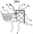
- the recess 5 a is formed by the outer peripheral wall of the protective cover 5, the bottom surface 23, and a stepped portion 24 that is a side wall on the yoke 3 side.
- FIG. 3 is an enlarged view of the recess 5a.
- a tip bending portion 5c is provided on the inner peripheral side of the recess 5a, and the tip bending portion 5c and the yoke end surface 3a are in contact with each other. Even if the ferrite magnet 4 is cracked or chipped, the fragments jump out to the rotor 102 so that the rotor 102 does not lock.
- the step plate 6 is provided with a step portion 6a that is in contact with the protruding portion 4a of the ferrite magnet 4 and defines the positions of the yoke end surface 3a and the protruding portion 4a.
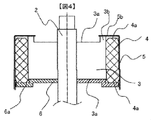
- FIG. 4 is a detailed cross-sectional view of the rotor 102 (No. 2).
- the rotor 102 includes a yoke 3 made of a solid iron core fixed to the shaft 2, a ferrite magnet 4 installed on the outer peripheral surface of the yoke 3, and an end plate 6 for positioning the ferrite magnet 4 in the axial direction.
- the ferrite magnet 4 is composed of a protective cover 5.
- a yoke step 3b that makes a business trip from the yoke end 3a.
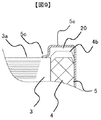
- the end surface of the protective cover 5 is provided with the L-shaped bending part 5b which is bent in the L-shape at the inner peripheral side.
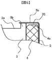
- FIG. 5 is an enlarged view of the L-shaped bent portion 5b.
- the L-shaped bent portion 5b is formed with a gap 20 so that the yoke step portion 3b is in contact with the protruding portion 4a and the protruding portion 4a and the L-shaped bent portion 5b are not in contact with each other. ing.
- the yoke step portion 3 b is a stepped portion that provides a gap between the protective cover 5 and the end face of the ferrite magnet 4.
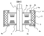
- FIG. 6 is a detailed cross-sectional view of the rotor 102 (No. 3).
- the rotor 102 is fixed to the shaft 2 and includes a yoke 3 in which a plurality of thin magnetic steel plates punched by pressing are laminated, a ferrite magnet 4 installed on the outer peripheral surface of the yoke 3, and an axial direction of the ferrite magnet 4.
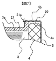
- a second step portion 21 a is provided on the outer peripheral side of the second end plate 21. Moreover, the end surface of the protective cover 5 is provided with the L-shaped bending part 5b which is bent in the L-shape at the inner peripheral side.
- FIG. 7 is an enlarged view of the L-shaped bent portion 5b.
- the L-shaped bent portion 5b When the protective cover 4 is press-fitted, the L-shaped bent portion 5b has a gap 20 so that the second stepped portion 21a contacts the protruding portion 4a and the protruding portion 4a and the L-shaped bent portion 5b do not contact each other. Is formed.
- FIG. 8 is a detailed sectional view (part 4) of the rotor 102.
- the rotor 102 includes a yoke 3 fixed to the shaft 2 and laminated with a plurality of thin magnetic steel plates, a ferrite magnet 4 installed on the outer peripheral surface of the yoke 3, an end plate 6 for axial positioning, a ferrite
- the magnet 4 includes a protective cover 5 for protecting the magnet 4 from external impacts and preventing the ferrite magnet 4 from scattering.
- the end plate 6 has a flat plate shape, and one end surface of the yoke end surface 3a and one end surface of the ferrite magnet 4 are configured to be flush with each other by the end plate 6.
- the protective cover 5 is provided with a recess 5a.
- FIG. 9 is an enlarged view of the recess 5a.
- the ferrite magnet 4 may be provided with a protruding portion 4b due to tolerance protruding from the yoke end surface 3a due to variations in axial length tolerance, and the protective cover 5 may be protruded due to the tolerance by providing the recess 5a.
- a gap 20 is formed so as not to contact the portion 4b.
- the axial length of the yoke 3 and the ferrite magnet 4 is set so that the protruding portion 4b due to tolerance does not protrude from the yoke end surface 3a due to tolerance, the axial length of the yoke 3 is useless. It becomes longer than the axial length of the ferrite magnet 4.
- the clearance 20 can be formed even if the protrusion 4b due to tolerance protrudes from the yoke end surface 3a, and the axial length of the yoke 3 is minimized. It is light and advantageous in terms of cost.
- FIG. 10 is an enlarged view of the bent end portion 5c of the protective cover 5 and a structural diagram of tolerance absorption of the protective cover 5.
- FIG. 10 is an enlarged view of the bent end portion 5c of the protective cover 5 and a structural diagram of tolerance absorption of the protective cover 5.
- the tip bending portion 5c is bent at an obtuse angle, and when the protective cover 5 is press-fitted, the tip bending portion 5c comes into contact with the yoke end portion 3a, thereby making it possible to form the obtuse angle in a right angle direction.
- This structure has the effect of absorbing the dimensional tolerance of each part when it is bent from an obtuse angle to a right angle.
- the ferrite magnet 4 is temporarily cracked or chipped. However, there is an effect of preventing the broken and chipped pieces from scattering from the rotor 102.
- FIG. 11 is a detailed cross section (No. 5) of the rotor, and is a cross section immediately before press-fitting the protective cover 5.
- FIG. 12 shows a protective cover press-fitting structure (part 1).
- the end face of the ferrite magnet 4 is provided with a taper portion 4c.
- the taper portion 4c serves to position the protective cover 5, and the protective cover 5 can be easily press-fitted. There is.
- FIG. 13 shows a protective cover press-fitting structure (part 2).
- a protective cover step 5d is provided at the tip of the protective cover 5.
- the protective cover step 5d serves to position the protective cover 5 so that the protective cover 5 can be easily used. There is an effect that can be press-fitted into.
Landscapes
- Engineering & Computer Science (AREA)
- Power Engineering (AREA)
- Permanent Field Magnets Of Synchronous Machinery (AREA)
Abstract
Description
前記フェライト磁石端面は、前記ヨーク端面に対し突出しており、前記フェライト磁石端面と前記保護カバー底面との間に空隙を作るための段付き部を有することを特徴とする。
Claims (7)
- 筒状の固定子コアと、前記固定子コアの内周側に設置されたシャフトを備えた回転子と、前記シャフトに固定されたヨークと、前記ヨークの外周面に設置された少なくとも一つのフェライト磁石と、前記フェライト磁石の外周に配置された保護カバーとを備えた回転電機において、
前記フェライト磁石端面は、前記ヨーク端面に対し突出しており、前記フェライト磁石端面と前記保護カバー底面との間に空隙を作るための段付き部を有することを特徴とする回転電機。 - 請求項1に記載の回転電機において、
前記固定子コアは、前記フェライト磁石より短く、前記フェライト磁石が、前記固定子コアの両端に突出していることを特徴とする回転電機。 - 請求項1に記載の回転電機において、
前記保護カバーは、前記フェライト磁石の突出部を逃がすように、前記段付き部を有する凹部を設けたことを特徴とする回転電機。 - 請求項1に記載の回転電機において、
前記ヨークは、前記段付き部として外周側にヨーク段部を設け、前記保護カバーのL字曲げ部と前記ヨーク段部とが接触し、前記フェライト磁石の突出部との間に隙間を設けたことを特徴とする回転電機。 - 請求項3に記載の回転電機において、
前記保護カバーの凹部は、前記凹部の始まりに鈍角の曲げ部を設け、前記ヨークと前記曲げ部が接触し、前記曲げ部を鈍角から直角に近づける方向に変形させることを特徴とする回転電機。 - 請求項1に記載の回転電機おいて、
前記フェライト磁石の位置決めを行う段部を備えた端板があることを特徴とする回転電機。 - 請求項1に記載の回転電機において、
前記ヨークの端面に、第2の端板を備え、前記第2端板の外周側には、前記保護カバーのL字曲げ部と接触する第2の段部を設けて、前記フェライト磁石の突出部との間に隙間を設けたことを特徴とする回転電機。
Priority Applications (3)
| Application Number | Priority Date | Filing Date | Title |
|---|---|---|---|
| US14/892,426 US10411549B2 (en) | 2013-05-20 | 2014-03-12 | Rotating electric machine having protective cover for improving rotor |
| JP2015518128A JP6100371B2 (ja) | 2013-05-20 | 2014-03-12 | 回転電機 |
| CN201480038525.2A CN105359382B (zh) | 2013-05-20 | 2014-03-12 | 旋转电机 |
Applications Claiming Priority (2)
| Application Number | Priority Date | Filing Date | Title |
|---|---|---|---|
| JP2013-105725 | 2013-05-20 | ||
| JP2013105725 | 2013-05-20 |
Publications (1)
| Publication Number | Publication Date |
|---|---|
| WO2014188766A1 true WO2014188766A1 (ja) | 2014-11-27 |
Family
ID=51933332
Family Applications (1)
| Application Number | Title | Priority Date | Filing Date |
|---|---|---|---|
| PCT/JP2014/056391 Ceased WO2014188766A1 (ja) | 2013-05-20 | 2014-03-12 | 回転電機 |
Country Status (4)
| Country | Link |
|---|---|
| US (1) | US10411549B2 (ja) |
| JP (1) | JP6100371B2 (ja) |
| CN (1) | CN105359382B (ja) |
| WO (1) | WO2014188766A1 (ja) |
Cited By (7)
| Publication number | Priority date | Publication date | Assignee | Title |
|---|---|---|---|---|
| KR20170045998A (ko) * | 2015-10-20 | 2017-04-28 | 엘지이노텍 주식회사 | 로터 조립체 및 이를 포함하는 모터 |
| JP2017158340A (ja) * | 2016-03-02 | 2017-09-07 | 株式会社ミツバ | 電動モータのロータ、およびロータの製造方法 |
| JP2018107975A (ja) * | 2016-12-28 | 2018-07-05 | 株式会社デンソー | 電動モータ |
| JP2020048268A (ja) * | 2018-09-14 | 2020-03-26 | 株式会社ミツバ | 電動モータおよび電動モータの製造方法 |
| JP2020089005A (ja) * | 2018-11-21 | 2020-06-04 | 株式会社ミツバ | ロータ、及び、モータ |
| JP2023046761A (ja) * | 2021-09-24 | 2023-04-05 | 株式会社ミツバ | ロータ、電動モータ、及びロータの組み立て方法 |
| WO2025169763A1 (ja) * | 2024-02-07 | 2025-08-14 | パナソニックIpマネジメント株式会社 | ロータ、モータ |
Families Citing this family (12)
| Publication number | Priority date | Publication date | Assignee | Title |
|---|---|---|---|---|
| DE102016222614B4 (de) | 2016-11-17 | 2024-06-06 | Robert Bosch Gmbh | Stator einer elektrischen Maschine, eine elektrische Maschine, sowie Verfahren zum Herstellen einer solchen |
| CN109546832B (zh) * | 2017-09-21 | 2021-08-10 | 德昌电机(深圳)有限公司 | 无刷直流电机及其双离合变速器 |
| JP7200240B2 (ja) * | 2017-12-27 | 2023-01-06 | 安徽美芝精密制造有限公司 | 永久磁石モーター及びコンプレッサー |
| US11764626B2 (en) * | 2018-08-03 | 2023-09-19 | Nidec Corporation | Rotor and motor |
| JP2020048267A (ja) * | 2018-09-14 | 2020-03-26 | 株式会社ミツバ | 電動モータおよび電動モータの製造方法 |
| WO2020105479A1 (ja) | 2018-11-21 | 2020-05-28 | 株式会社ミツバ | ロータ、モータ、及び、ロータの製造方法 |
| CN110867991B (zh) * | 2019-11-14 | 2021-09-24 | 中国船舶重工集团公司第七0七研究所 | 整装式直流无刷有限转角力矩电机转子磁钢封闭结构及方法 |
| CN111654171A (zh) * | 2020-06-24 | 2020-09-11 | 抚顺煤矿电机制造有限责任公司 | 一种永磁电机转子装配结构 |
| US11916447B2 (en) | 2021-06-07 | 2024-02-27 | Black & Decker Inc. | Overmolded rotor structure |
| US12068639B2 (en) | 2021-06-07 | 2024-08-20 | Black & Decker Inc. | Motor rotor with sleeve for retention of magnet ring |
| DE102021211307A1 (de) | 2021-10-07 | 2023-04-13 | Siemens Energy Global GmbH & Co. KG | Stabilisierte Endzonenbereiche eines Ständerblechpakets durch Segmente, elektrische Maschine und Verfahren zur Herstellung oder Reparatur |
| CN116032088A (zh) * | 2023-02-01 | 2023-04-28 | 广东威灵电机制造有限公司 | 电机及具有其的电器设备 |
Citations (5)
| Publication number | Priority date | Publication date | Assignee | Title |
|---|---|---|---|---|
| JPH06105505A (ja) * | 1992-09-17 | 1994-04-15 | Aichi Emerson Electric Co Ltd | 磁石回転子の製造方法 |
| JPH06153427A (ja) * | 1992-04-15 | 1994-05-31 | Aichi Emerson Electric Co Ltd | 永久磁石付回転子 |
| JP2004254394A (ja) * | 2003-02-19 | 2004-09-09 | Mitsubishi Electric Corp | 回転電機 |
| JP2012070585A (ja) * | 2010-09-27 | 2012-04-05 | Keihin Corp | 回転電機用ロータ |
| JP2013021780A (ja) * | 2011-07-08 | 2013-01-31 | Toshiba Industrial Products Manufacturing Corp | 回転電機 |
Family Cites Families (10)
| Publication number | Priority date | Publication date | Assignee | Title |
|---|---|---|---|---|
| US6153427A (en) * | 1994-10-12 | 2000-11-28 | Northeastern Ohio Universities College Of Medicine | Erythropoietin-inducible, erythroid-specific DNA construct |
| US6105505A (en) * | 1998-06-17 | 2000-08-22 | Lockheed Martin Corporation | Hard target incendiary projectile |
| JP4469080B2 (ja) * | 2000-12-13 | 2010-05-26 | 信越化学工業株式会社 | 脂環構造を有する新規第三級アルコール化合物 |
| US8137805B2 (en) * | 2007-06-21 | 2012-03-20 | Caterpillar Inc. | Manganese based coating for wear and corrosion resistance |
| US8138649B2 (en) * | 2007-08-02 | 2012-03-20 | Remy Technologies, L.L.C. | Magnet support and retention system for hybrid rotors |
| JP4671997B2 (ja) * | 2007-10-23 | 2011-04-20 | 三菱電機株式会社 | 回転電機の回転子、及びその製造方法 |
| JP2009112158A (ja) * | 2007-10-31 | 2009-05-21 | Aisan Ind Co Ltd | ロータ及びポンプ |
| JP5842365B2 (ja) * | 2011-04-02 | 2016-01-13 | 日本電産株式会社 | ロータユニット、回転電機、およびロータユニットの製造方法 |
| WO2014181576A1 (ja) * | 2013-05-07 | 2014-11-13 | 日立オートモティブシステムズ株式会社 | 回転電機の磁石飛散防止及び保持構造 |
| JP6349140B2 (ja) * | 2014-04-24 | 2018-06-27 | Kyb株式会社 | ロータ、ロータの製造方法及びロータを備える回転電機 |
-
2014
- 2014-03-12 JP JP2015518128A patent/JP6100371B2/ja active Active
- 2014-03-12 WO PCT/JP2014/056391 patent/WO2014188766A1/ja not_active Ceased
- 2014-03-12 US US14/892,426 patent/US10411549B2/en active Active
- 2014-03-12 CN CN201480038525.2A patent/CN105359382B/zh active Active
Patent Citations (5)
| Publication number | Priority date | Publication date | Assignee | Title |
|---|---|---|---|---|
| JPH06153427A (ja) * | 1992-04-15 | 1994-05-31 | Aichi Emerson Electric Co Ltd | 永久磁石付回転子 |
| JPH06105505A (ja) * | 1992-09-17 | 1994-04-15 | Aichi Emerson Electric Co Ltd | 磁石回転子の製造方法 |
| JP2004254394A (ja) * | 2003-02-19 | 2004-09-09 | Mitsubishi Electric Corp | 回転電機 |
| JP2012070585A (ja) * | 2010-09-27 | 2012-04-05 | Keihin Corp | 回転電機用ロータ |
| JP2013021780A (ja) * | 2011-07-08 | 2013-01-31 | Toshiba Industrial Products Manufacturing Corp | 回転電機 |
Cited By (10)
| Publication number | Priority date | Publication date | Assignee | Title |
|---|---|---|---|---|
| KR20170045998A (ko) * | 2015-10-20 | 2017-04-28 | 엘지이노텍 주식회사 | 로터 조립체 및 이를 포함하는 모터 |
| KR102523835B1 (ko) | 2015-10-20 | 2023-04-20 | 엘지이노텍 주식회사 | 로터 조립체 및 이를 포함하는 모터 |
| JP2017158340A (ja) * | 2016-03-02 | 2017-09-07 | 株式会社ミツバ | 電動モータのロータ、およびロータの製造方法 |
| JP2018107975A (ja) * | 2016-12-28 | 2018-07-05 | 株式会社デンソー | 電動モータ |
| JP2020048268A (ja) * | 2018-09-14 | 2020-03-26 | 株式会社ミツバ | 電動モータおよび電動モータの製造方法 |
| JP7149783B2 (ja) | 2018-09-14 | 2022-10-07 | 株式会社ミツバ | 電動モータおよび電動モータの製造方法 |
| JP2020089005A (ja) * | 2018-11-21 | 2020-06-04 | 株式会社ミツバ | ロータ、及び、モータ |
| JP7080805B2 (ja) | 2018-11-21 | 2022-06-06 | 株式会社ミツバ | ロータ、及び、モータ |
| JP2023046761A (ja) * | 2021-09-24 | 2023-04-05 | 株式会社ミツバ | ロータ、電動モータ、及びロータの組み立て方法 |
| WO2025169763A1 (ja) * | 2024-02-07 | 2025-08-14 | パナソニックIpマネジメント株式会社 | ロータ、モータ |
Also Published As
| Publication number | Publication date |
|---|---|
| JP6100371B2 (ja) | 2017-03-22 |
| US10411549B2 (en) | 2019-09-10 |
| US20160149461A1 (en) | 2016-05-26 |
| CN105359382B (zh) | 2018-01-16 |
| CN105359382A (zh) | 2016-02-24 |
| JPWO2014188766A1 (ja) | 2017-02-23 |
Similar Documents
| Publication | Publication Date | Title |
|---|---|---|
| JP6100371B2 (ja) | 回転電機 | |
| KR101854386B1 (ko) | 전자 모터용 고정자의 권선 절연 구조 | |
| CN101783534B (zh) | 电动机 | |
| US7622841B2 (en) | Motor | |
| JP5414903B2 (ja) | 回転電機 | |
| US10985623B2 (en) | Electric motor and rotor thereof | |
| JP6120991B2 (ja) | 永久磁石埋込型電動機 | |
| EP3754814B1 (en) | Stator core and compressor | |
| JP2012161226A (ja) | 回転電機用回転子 | |
| JP2015116022A (ja) | 回転電機ロータ | |
| CN104380577B (zh) | 旋转电机 | |
| JP6621058B2 (ja) | 回転電機及び回転電機の製造方法 | |
| KR20160076729A (ko) | 로터 조립체, 이의 제조방법 및 로터 조립체를 구비하는 모터 | |
| US20150091404A1 (en) | Rotor for rotating electric machine, rotating electric machine, and magnetizing apparatus for rotating electric machine | |
| WO2017158847A1 (ja) | 回転電機及び回転電機の製造方法 | |
| CN106816996B (zh) | 用于绕线转子同步电机的转子 | |
| JP6013989B2 (ja) | 回転電機及びその組立方法 | |
| WO2017122445A1 (ja) | 回転電機の固定子、回転電機、および回転電機の固定子の製造方法 | |
| JP5665362B2 (ja) | 回転電機 | |
| JP5987658B2 (ja) | モールドモータ | |
| JP2015220950A (ja) | 回転電機 | |
| JP6004901B2 (ja) | レゾルバ | |
| JP5132429B2 (ja) | ブラシ付モータ | |
| WO2019064747A1 (ja) | ロータ及びそのロータを備えたモータ | |
| JP6015394B2 (ja) | モールドモータ |
Legal Events
| Date | Code | Title | Description |
|---|---|---|---|
| WWE | Wipo information: entry into national phase |
Ref document number: 201480038525.2 Country of ref document: CN |
|
| 121 | Ep: the epo has been informed by wipo that ep was designated in this application |
Ref document number: 14801192 Country of ref document: EP Kind code of ref document: A1 |
|
| ENP | Entry into the national phase |
Ref document number: 2015518128 Country of ref document: JP Kind code of ref document: A |
|
| NENP | Non-entry into the national phase |
Ref country code: DE |
|
| WWE | Wipo information: entry into national phase |
Ref document number: 14892426 Country of ref document: US |
|
| 122 | Ep: pct application non-entry in european phase |
Ref document number: 14801192 Country of ref document: EP Kind code of ref document: A1 |