WO2014188759A1 - ヒートポンプシステム - Google Patents
ヒートポンプシステム Download PDFInfo
- Publication number
- WO2014188759A1 WO2014188759A1 PCT/JP2014/056139 JP2014056139W WO2014188759A1 WO 2014188759 A1 WO2014188759 A1 WO 2014188759A1 JP 2014056139 W JP2014056139 W JP 2014056139W WO 2014188759 A1 WO2014188759 A1 WO 2014188759A1
- Authority
- WO
- WIPO (PCT)
- Prior art keywords
- heat
- hot water
- path
- heat pump
- temperature
- Prior art date
- Legal status (The legal status is an assumption and is not a legal conclusion. Google has not performed a legal analysis and makes no representation as to the accuracy of the status listed.)
- Ceased
Links
Images
Classifications
-
- F—MECHANICAL ENGINEERING; LIGHTING; HEATING; WEAPONS; BLASTING
- F24—HEATING; RANGES; VENTILATING
- F24D—DOMESTIC- OR SPACE-HEATING SYSTEMS, e.g. CENTRAL HEATING SYSTEMS; DOMESTIC HOT-WATER SUPPLY SYSTEMS; ELEMENTS OR COMPONENTS THEREFOR
- F24D19/00—Details
- F24D19/10—Arrangement or mounting of control or safety devices
- F24D19/1006—Arrangement or mounting of control or safety devices for water heating systems
- F24D19/1051—Arrangement or mounting of control or safety devices for water heating systems for domestic hot water
- F24D19/1054—Arrangement or mounting of control or safety devices for water heating systems for domestic hot water the system uses a heat pump
-
- F—MECHANICAL ENGINEERING; LIGHTING; HEATING; WEAPONS; BLASTING
- F24—HEATING; RANGES; VENTILATING
- F24D—DOMESTIC- OR SPACE-HEATING SYSTEMS, e.g. CENTRAL HEATING SYSTEMS; DOMESTIC HOT-WATER SUPPLY SYSTEMS; ELEMENTS OR COMPONENTS THEREFOR
- F24D17/00—Domestic hot-water supply systems
- F24D17/0026—Domestic hot-water supply systems with conventional heating means
- F24D17/0031—Domestic hot-water supply systems with conventional heating means with accumulation of the heated water
-
- F—MECHANICAL ENGINEERING; LIGHTING; HEATING; WEAPONS; BLASTING
- F24—HEATING; RANGES; VENTILATING
- F24D—DOMESTIC- OR SPACE-HEATING SYSTEMS, e.g. CENTRAL HEATING SYSTEMS; DOMESTIC HOT-WATER SUPPLY SYSTEMS; ELEMENTS OR COMPONENTS THEREFOR
- F24D17/00—Domestic hot-water supply systems
- F24D17/02—Domestic hot-water supply systems using heat pumps
-
- F—MECHANICAL ENGINEERING; LIGHTING; HEATING; WEAPONS; BLASTING
- F24—HEATING; RANGES; VENTILATING
- F24H—FLUID HEATERS, e.g. WATER OR AIR HEATERS, HAVING HEAT-GENERATING MEANS, e.g. HEAT PUMPS, IN GENERAL
- F24H15/00—Control of fluid heaters
- F24H15/10—Control of fluid heaters characterised by the purpose of the control
- F24H15/136—Defrosting or de-icing; Preventing freezing
-
- F—MECHANICAL ENGINEERING; LIGHTING; HEATING; WEAPONS; BLASTING
- F24—HEATING; RANGES; VENTILATING
- F24H—FLUID HEATERS, e.g. WATER OR AIR HEATERS, HAVING HEAT-GENERATING MEANS, e.g. HEAT PUMPS, IN GENERAL
- F24H15/00—Control of fluid heaters
- F24H15/20—Control of fluid heaters characterised by control inputs
- F24H15/258—Outdoor temperature
-
- F—MECHANICAL ENGINEERING; LIGHTING; HEATING; WEAPONS; BLASTING
- F24—HEATING; RANGES; VENTILATING
- F24H—FLUID HEATERS, e.g. WATER OR AIR HEATERS, HAVING HEAT-GENERATING MEANS, e.g. HEAT PUMPS, IN GENERAL
- F24H15/00—Control of fluid heaters
- F24H15/30—Control of fluid heaters characterised by control outputs; characterised by the components to be controlled
- F24H15/355—Control of heat-generating means in heaters
- F24H15/37—Control of heat-generating means in heaters of electric heaters
-
- F—MECHANICAL ENGINEERING; LIGHTING; HEATING; WEAPONS; BLASTING
- F24—HEATING; RANGES; VENTILATING
- F24D—DOMESTIC- OR SPACE-HEATING SYSTEMS, e.g. CENTRAL HEATING SYSTEMS; DOMESTIC HOT-WATER SUPPLY SYSTEMS; ELEMENTS OR COMPONENTS THEREFOR
- F24D2200/00—Heat sources or energy sources
- F24D2200/04—Gas or oil fired boiler
-
- F—MECHANICAL ENGINEERING; LIGHTING; HEATING; WEAPONS; BLASTING
- F24—HEATING; RANGES; VENTILATING
- F24D—DOMESTIC- OR SPACE-HEATING SYSTEMS, e.g. CENTRAL HEATING SYSTEMS; DOMESTIC HOT-WATER SUPPLY SYSTEMS; ELEMENTS OR COMPONENTS THEREFOR
- F24D2200/00—Heat sources or energy sources
- F24D2200/12—Heat pump
- F24D2200/123—Compression type heat pumps
Definitions
- This specification relates to a heat pump system.
- JP 2009-156495 A discloses a heat pump system including a heat pump unit including a heat pump that absorbs heat from outside air and heats the heat medium, and a tank unit including a tank that stores the heat medium.
- a heat pump unit including a heat pump that absorbs heat from outside air and heats the heat medium
- a tank unit including a tank that stores the heat medium.
- the heat pump system in order to prevent the heat medium from freezing, it is possible to perform an antifreeze operation in which heating is performed while circulating the heat medium between the tank and the heat pump.
- the heat medium is heated by the heat pump in the freeze prevention operation.
- heating of the heat medium by the heat pump is high in energy efficiency, it is preferable to heat the heat medium to prevent freezing by driving the heat pump.
- the heat pump in a system having only a heat pump as a heat source, even when the outside air temperature is low, not only for anti-freezing operation but also when it is necessary to store heat in the tank, for example, when hot water for hot water supply needs to be stored It is necessary to drive the heat pump.
- the heat pump is driven in a situation where the outside air temperature is low, there is a possibility that the evaporator that performs heat exchange between the refrigerant of the heat pump and the outside air may be frosted.
- the evaporator is frosted, drainage is generated along with the defrosting operation, so that a separate measure for preventing the drain from freezing is required.
- a defrosting operation is always required, so that a drain freezing prevention measure is also necessarily required. For this reason, it is preferable that the evaporator of the heat pump is not frosted as much as possible.
- the present specification provides a technique for solving the above problems.
- the present specification provides a technology capable of preventing a situation in which a heat pump heated by a heat pump accumulates in a tank, and prevents a frost from forming on the evaporator of the heat pump due to the freeze prevention operation.
- the heat pump system disclosed in this specification includes a heat pump unit including a heat pump that absorbs heat from outside air and heats the heat medium, a tank unit including a tank that stores the heat medium, and an auxiliary heat source unit that heats the heat medium. .
- the heat pump system further includes an outside air temperature detecting means for detecting the outside air temperature, and a heater provided in a flow path through which the heat medium flows between the tank and the heat pump.
- the heat pump system can execute an anti-freezing operation in which the heat medium is heated while circulating the heat medium between the tank and the heat pump. In the anti-freezing operation, the heat pump system heats the heat medium with a heat pump when the outside air temperature is high, and heats the heat medium with a heater when the outside air temperature is low.
- the heating means used in the freeze prevention operation is switched according to the outside air temperature.
- the outside air temperature is high, energy efficiency can be increased by heating the heat medium with a heat pump.
- frosting on the evaporator of the heat pump can be prevented by heating the heat medium with a heater and not heating the heat medium with a heat pump.
- the heat pump system described above can heat the heat medium using the auxiliary heat source unit even when the heat pump unit is not driven when the outside air temperature is low, for example, to produce and supply hot water for hot water supply. As a result, convenience is not impaired.
- Any auxiliary heat source unit may be used as long as it is a heat source that does not form frost upon driving, such as a gas heat source unit, a gas engine cogeneration unit, a fuel cell, or a heater.
- the above heat pump system can be configured such that a heater is provided in the flow path inside the tank unit.
- the detection value of the thermistor (the thermistor for detecting the temperature of the heat medium or the thermistor for detecting the temperature of the refrigerant circulating in the heat pump) in the heat pump unit is affected by the heat radiation from the heater. Can be prevented.
- the above heat pump system can be configured such that a heater is provided in the flow path where the heat medium returns from the heat pump to the tank.
- the flow of the heat medium from the tank to the heat pump is more likely to freeze the heat medium than the flow path of the heat medium from the heat pump to the tank. For this reason, the necessity of the freeze prevention operation is often determined based on the temperature of the heat medium detected in the flow path for sending the heat medium from the tank to the heat pump.
- the detection value of the thermistor provided in the flow path for sending the heat medium from the tank to the heat pump is from the heater. It can be prevented from being affected by heat dissipation.
- FIG. 1 shows a configuration of a hot water supply system 10 of this embodiment.
- the hot water supply system 10 includes a hot water storage unit 20, an HP heat source unit 40, a gas heat source unit 50, and a controller 11.
- the HP heat source unit 40 includes a compressor 41, a first heat exchanger 43 that is a condenser, an expansion valve 44, and a heat pump 40a that includes a second heat exchanger 45 that is an evaporator.
- the discharge side of the compressor 41, the four-way valve 42, the refrigerant flow path 43a of the first heat exchanger 43, the expansion valve 44, the second heat exchanger 45, the four-way valve 42, and the suction side of the compressor 41 are refrigerant.
- the pipes 46 are connected in order, and the refrigerant circulates in this order.
- the refrigerant may be, for example, R744 (CO2 refrigerant) or R410A (HFC refrigerant).
- the first heat exchanger 43 includes a refrigerant channel 43a and a circulating water channel 43b.
- a fan 45 a is installed in the vicinity of the second heat exchanger 45.
- the second heat exchanger 45 performs heat exchange between the outside air sent by the fan 45a and the refrigerant.
- a defrosting path 47 is connected to the refrigerant pipe 46 between the discharge side of the compressor 41 and the four-way valve 42, and between the expansion valve 44 and the second heat exchanger 45. In the defrosting path 47, a defrosting valve 47a is provided.
- a circulation forward connection path 48 is connected to the inlet side of the circulating water flow path 43b of the first heat exchanger 43, and a circulation return path connection path 49 is connected to the outlet side.
- the circulation path connection path 48 is provided with an inlet side thermistor 48a
- the circulation path connection path 49 is provided with an outlet side thermistor 49a.
- the inlet side thermistor 48a detects the temperature of the circulating water flowing into the circulating water flow path 43b of the first heat exchanger 43
- the outlet side thermistor 49a is the circulating water flowing out of the circulating water flow path 43b of the first heat exchanger 43. Detect the temperature.
- each thermistor 48a, 49a outputs a detection signal corresponding to the water temperature, and this signal is input to the controller 11 to detect the water temperature.
- the expression that a thermistor or sensor detects actually means that the temperature or the flow rate of water is detected by inputting these detection signals to the controller 11.
- the hot water storage unit 20 includes a hot water storage tank 21 and a mixer 24.
- a water supply path 22 for supplying tap water to the hot water tank 21 is connected to the bottom of the hot water tank 21.
- a pressure reducing valve 23 is provided in the vicinity of the tap water inlet 22 a of the water supply path 22.
- the pressure reducing valve 23 adjusts the water supply pressure to the water supply path 22.
- a mixed water supply path 26 of the mixer 24 is connected to the downstream side of the pressure reducing valve 23 of the water supply path 22.
- a water supply control valve 26a, a water supply flow rate sensor 26b, and a water supply thermistor 26c are provided in the mixed water supply path 26.
- the water supply control valve 26 a adjusts the flow rate of tap water flowing through the mixed water supply path 26.
- the water supply flow rate sensor 26 b and the water supply thermistor 26 c detect the flow rate and temperature of tap water flowing through the mixed water supply path 26.
- the downstream pressure of the pressure reducing valve 23 decreases.
- the pressure reducing valve 23 opens when the downstream pressure decreases, and tries to maintain the pressure at a predetermined pressure regulation value. For this reason, when the hot water in the hot water storage tank 21 decreases or the water supply control valve 26a of the mixer 24 is opened, tap water is supplied thereto.
- a drainage path 31 is connected to the downstream side of the connection portion of the mixed water supply path 26.
- a drain valve 32 is provided in the middle of the drain path 31. The drain valve 32 can be manually opened and closed. When the drain valve 32 is opened, the water in the hot water tank 21 is drained to the outside through the drain path 31.
- a circulation outward path 33 is connected to the bottom of the hot water tank 21, and one end of a circulation return path 34 is connected to the upper part of the hot water tank 21.
- the other end of the circulation outward path 33 is connected to the circulation outward path connection path 48 of the HP heat source unit 40, and the other end of the circulation return path 34 is connected to the circulation return path connection path 49.
- a circulation thermistor 36 and a circulation pump 37 are provided in the circulation outward path 33. The outward thermistor 36 detects the temperature of the water that has flowed out of the hot water storage tank 21 into the circulation outward path 33.
- an electric freeze prevention heater 34a is provided in the circulation return path 34 inside the tank unit 20, an electric freeze prevention heater 34a is provided in the circulation return path 34 inside the tank unit 20, an electric freeze prevention heater 34a is provided.
- a pressure release path 38 is connected in the middle of the circulation return path 34, and a relief valve 38 a is provided in the pressure release path 38.
- the valve opening pressure of the relief valve 38 a is set slightly higher than the pressure regulation value of the pressure reducing valve 23.
- the relief valve 38a is opened to prevent the pressure in the hot water storage tank 21 from exceeding the pressure that can withstand pressure.
- an upper thermistor 39 is attached to a predetermined amount (for example, 30 liters) from the upper end.
- the upper thermistor 39 detects the water temperature at the upper part of the hot water tank 21.
- the hot water storage unit 20 is also provided with an outside air temperature thermistor 35 that detects the outside air temperature.
- the hot water path 25 of the mixer 24 is connected to the upper part of the hot water tank 21.
- the warm water path 25 is provided with a warm water control valve 25a, a warm water flow rate sensor 25b, and a warm water thermistor 25c.
- the hot water control valve 25 a adjusts the flow rate of water flowing from the hot water tank 21 to the hot water path 25.
- the hot water flow rate sensor 25 b detects the flow rate of water flowing from the hot water storage tank 21 to the hot water path 25.
- the hot water thermistor 25 c detects the temperature of the water flowing through the hot water path 25.
- the warm water path 25 and the mixed water supply path 26 merge and are connected to the first mixing path 27.
- the first mixing path 27 is provided with a mixing thermistor 27 a that detects the temperature of the mixed water flowing through the first mixing path 27.
- the hot water storage unit 20 includes a first hot water supply path 29.
- a hot water supply thermistor 29 a is provided in the first hot water supply path 29.
- a hot-water tap 60 is connected to the tip of the first hot water supply path 29.
- the hot-water tap 60 is arranged in a bathroom, a washroom, a kitchen, etc. (in FIG. 1, the plurality of hot-water taps 60 are represented by one).
- the middle of the first mixing path 27 and the middle of the first hot water supply path 29 are connected by a hot water supply bypass path 28.
- the hot water supply bypass path 28 is provided with a bypass control valve 28a.
- the gas heat source unit 50 includes a burner heat exchanger 52, a burner 53, and the like.
- the mixed water from the first mixing path 27 of the hot water storage unit 20 flows into the burner heat exchanger 52 through the second mixing path 51.
- the second mixing path 51 is provided with an incoming water thermistor 51a, a hot water supply flow rate sensor 51b, and a water amount servo 51c.
- the incoming water thermistor 51a and the hot water supply flow rate sensor 51b detect the temperature and flow rate of the water flowing through the second mixing path 51, respectively.
- the water amount servo 51 c adjusts the flow rate of water flowing through the second mixing path 51.
- the gas combustion type burner 53 heats the burner heat exchanger 52.
- the water heated by the burner heat exchanger 52 flows into the first hot water supply path 29 of the hot water storage unit 20 through the second hot water supply path 54.
- a can body thermistor 55 is provided near the outlet of the burner heat exchanger 52, and a hot water thermistor 56 is provided downstream thereof.
- a heat source bypass path 57 is connected between the downstream side of the water amount servo 51 c in the second mixing path 51 and the can body thermistor 55 and the hot water thermistor 56 in the second hot water supply path 54.
- a heat source unit bypass control valve 58 is provided at a connection portion between the second mixing path 51 and the heat source unit bypass path 57. By adjusting the opening degree of the heat source unit bypass control valve 58, a part of the water flowing through the second mixing path 51 flows into the heat source unit bypass path 57, and the flow rate of the water is adjusted.
- the controller 11 includes a CPU, a ROM, a RAM, and the like. Various operation programs are stored in the ROM.
- the RAM temporarily stores various signals input to the controller 11 and various data generated in the course of execution of processing by the CPU. Specifically, the detection signals of the various thermistors 25c, 26c, 27a, 29a, 35, 36, 39, 48a, 49a, 51a, 55, 56 and the flow sensors 25b, 26b, 51b are input to the RAM. These pieces of information are temporarily stored.
- the CPU outputs drive signals to various devices such as the hot water storage unit 20, the HP heat source unit 40, and the gas heat source unit 50 based on information stored in the ROM and RAM.
- a remote controller 13 is connected to the controller 11.
- the remote controller 13 is provided with a switch 16 for operating the hot water supply system 10, a liquid crystal display 17 for displaying an operation state of the hot water supply system 10, and the like, and information set by the remote controller 13 is input to the controller 11. .
- Heat storage operation In the hot water supply system 10, it is possible to execute a heat storage operation in which the water in the hot water storage tank 21 is heated by the heat pump 40 a to be hot hot water, and the hot water is stored in the hot water storage tank 21.
- the compressor 41 is driven in the HP heat source unit 40.
- the refrigerant compressed by the compressor 41 flows through the refrigerant channel 43a of the first heat exchanger 43, the circulating water flowing through the circulating water channel 43b is heated.
- the refrigerant that has flowed out of the refrigerant flow path 43a is expanded and cooled by the expansion valve 44, and when it flows through the second heat exchanger 45, it absorbs heat from the outside air and rises in temperature.
- the temperature of the refrigerant that has been raised flows into the compressor 41 and is compressed again, so that the temperature is further raised.
- the circulation pump 37 is operated, and the water in the hot water storage tank 21 is sucked out from the bottom of the hot water storage tank 21 to the circulation outward path 33.
- the water sucked into the circulation outward path 33 is heated and increases in temperature when passing through the circulation water flow path 43b of the first heat exchanger 43 of the HP heat source unit 40.
- the hot water whose temperature has risen flows through the circulation return path 34 and is returned to the upper part of the hot water tank 21.
- the hot water storage tank 21 forms a temperature stratification in which the high temperature layer is laminated on the upper side of the low temperature layer.
- the thickness (depth) of the high temperature layer gradually increases, and when hot water is stored to the maximum, hot water is stored in the entire hot water tank 21. Become.
- hot hot water can be sent out to the hot water path 25 connected to the upper part of the hot water storage tank 21. It becomes possible.
- Hot water operation In the hot water supply operation, the mixed water adjusted to the hot water supply set temperature by the mixer 24 was adjusted to a temperature lower than the hot water supply set temperature by the first hot water supply operation for supplying hot water from the hot water tap 60 through the hot water supply bypass path 28.
- One of the 2nd hot water supply operation which heats mixed water with gas heat source unit 50, and supplies hot water from hot-water tap 60 is performed.
- the first hot water operation is performed. Is called.
- the controller 11 opens the bypass control valve 28a and fully closes the water amount servo 51c.
- the controller 11 adjusts the opening degree of the hot water control valve 25a and the opening degree of the water supply control valve 26a so that the water temperature detected by the mixing thermistor 27a becomes the hot water supply set temperature.
- the mixed water adjusted to the hot water supply set temperature flows through the first mixing path 27, and then hot water is supplied from the hot water tap 60 through the hot water supply bypass path 28 and the first hot water supply path 29.
- the second hot water supply operation is performed.
- the controller 11 fully closes the bypass control valve 28a and sets the water amount servo 51c to a predetermined opening.
- the controller 11 determines the opening of the hot water control valve 25a and the water supply control valve 26a so that the water temperature detected by the mixing thermistor 27a becomes a second reference temperature (for example, the hot water supply set temperature -5 ° C.) lower than the hot water supply set temperature. Adjust the opening.
- the mixed water adjusted to the second reference temperature flows through the first mixing path 27, flows through the second mixing path 51 of the gas heat source unit 50, flows into the burner heat exchanger 52, and is heated by the burner 53.
- the heating capacity of the burner 53 is controlled so that the water temperature detected by the can body thermistor 55 provided at the outlet of the burner heat exchanger 52 is 60 ° C. or higher. Thereby, it can suppress that dew condensation water generate
- a part of the mixed water flowing through the second mixing path 51 flows into the second hot water supply path 54 through the heat source unit bypass path 57, and water of 60 ° C. or higher from the burner heat exchanger 52 and the second from the heat source unit bypass path 57.
- the water at the reference temperature is mixed, and the water at the hot water supply set temperature is sent to the first hot water supply path 29.
- the water adjusted to the hot water supply set temperature is supplied from the hot water tap 60 through the first hot water supply path 29.
- the second heat exchanger 45 may be frosted. If the second heat exchanger 45 is frosted, the efficiency of heat exchange with the outside air is lowered, and the heating capacity of the circulating water in the heat pump 40a is lowered. Therefore, in the hot water supply system 10 of the present embodiment, when the second heat exchanger 45 is frosted, a defrosting operation for defrosting from the second heat exchanger 45 can be performed. In the defrosting operation, in the HP heat source unit 40, the compressor 41 is driven with the defrosting valve 47a opened.
- the high-temperature refrigerant discharged from the compressor 41 flows to the second heat exchanger 45 through the defrosting path 47 and circulates back to the compressor 41 as indicated by broken line arrows in FIG.
- the high-temperature refrigerant flows through the second heat exchanger 45, it can be defrosted from the second heat exchanger 45.
- step S202 it is determined whether or not the temperature of the circulating water is lower than a predetermined temperature (for example, 10 ° C.).
- a predetermined temperature for example, 10 ° C.
- the temperature of the circulating water refers to the temperature of the circulating water in the circulating outbound path 33 detected by the outbound thermistor 36 and the circulating water in the circulating outbound connection path 48 detected by the inlet-side thermistor 48a. It means the lower one of the temperatures. If the temperature of the circulating water is equal to or higher than the predetermined temperature (NO in step S202), the process returns to step S202. When the temperature of the circulating water is lower than the predetermined temperature (YES in step S202), the process proceeds to step S204.
- step S204 it is determined whether or not the outside air temperature detected by the outside air temperature thermistor 35 is lower than a predetermined temperature (for example, 5 ° C.). If the outside air temperature is equal to or higher than the predetermined temperature (NO in step S204), the process returns to step S202. If the outside air temperature falls below the predetermined temperature (YES in step S204), the process proceeds to step S206.
- a predetermined temperature for example, 5 ° C.
- step S206 the circulation pump 37 is driven. Thereby, the circulating water is sucked out from the lower part of the hot water storage tank 21, and the circulation outward path 33, the circulation outbound path connection path 48, the circulation water path 43 b of the first heat exchanger 43, the circulation return path connection path 49, and the circulation return path 34 are sequentially arranged. Via, the circulating water is returned to the upper part of the hot water tank 21. The circulating water inside the circulation outward path 33, the circulation outbound path connection path 48, the circulation water flow path 43b of the first heat exchanger 43, the circulation return path connection path 49, and the circulation return path 34 is replaced by the flow of the circulating water.
- step S208 the temperature of the circulating water (the temperature of the circulating water in the circulating outbound path 33 detected by the outbound path thermistor 36 and the temperature of the circulating water in the circulating outbound path connection path 48 detected by the inlet-side thermistor 48a is low. It is determined whether or not the temperature is higher than a predetermined temperature (for example, 13 ° C.). If residual heat remains in the hot water storage tank 21 when the freeze prevention operation is started in step S206, the circulation pump 37 is driven to circulate the circulation outward path 33, the circulation outward path connection path 48, and the first heat exchanger 43.
- a predetermined temperature for example, 13 ° C.
- Circulating water inside the water flow path 43 b, the circulation return path connection path 49, and the circulation return path 34 is replaced with warm circulating water from the hot water storage tank 21. In this case, there is no need to continue the freeze prevention operation. Accordingly, when the temperature of the circulating water becomes equal to or higher than the predetermined temperature in step S208 (YES), the process proceeds to step S228, the circulation pump 37 is stopped, and the freeze prevention operation is ended. If the temperature of the circulating water is less than the predetermined temperature in step S208 (in the case of NO), the process proceeds to step S210.
- step S210 it is determined whether or not the outside air temperature is equal to or higher than a predetermined temperature (for example, 6 ° C.). If the outside air temperature rises to a temperature at which the circulating water is not likely to freeze after starting the freeze prevention operation in step S206, it is not necessary to continue the freeze prevention operation any further. Accordingly, when the outside air temperature becomes equal to or higher than the predetermined temperature in step S210 (YES), the process proceeds to step S228, the circulation pump 37 is stopped, and the freeze prevention operation is ended. If the outside air temperature is less than the predetermined temperature in step S210 (NO), the process proceeds to step S212.
- a predetermined temperature for example, 6 ° C.
- step S212 it is determined whether or not a predetermined time (for example, 30 minutes) has elapsed since the circulation pump 37 was driven in step S206. If the predetermined time has not elapsed (NO in step S212), the process returns to step S208. If the predetermined time has elapsed (YES in step S212), the process proceeds to step S214. The process proceeds from step S212 to step S214 when the temperature of the circulating water does not reach the predetermined temperature (that is, no residual heat remains in the hot water storage tank 21) until a predetermined time has elapsed after the circulation pump 37 is driven. And the outside air temperature does not rise. In such a case, in the hot water supply system 10 of the present embodiment, the circulating water is heated in the processing after step S214.
- a predetermined time for example, 30 minutes
- step S214 it is determined whether or not the outside air temperature is below a predetermined temperature (for example, ⁇ 10 ° C.).
- a predetermined temperature for example, ⁇ 10 ° C.
- the second heat exchanger 45 may be frosted. If the second heat exchanger 45 is frosted, drainage is generated along with the defrosting operation, and therefore a separate measure for preventing the drain from freezing is required. For this reason, it is preferable that the second heat exchanger 45 is not frosted as much as possible. Therefore, in the hot water supply system 10 of the present embodiment, when the circulating water is heated in the freeze prevention operation, the heating means is switched according to the outside air temperature.
- step S216 the compressor 41 is driven and heating of the circulating water by the heat pump 40a is started.
- a predetermined temperature for example, 30 ° C.
- step S218 If the temperature of circulating water becomes more than predetermined temperature by step S218 (it becomes YES), the compressor 41 will be stopped by step S220 and the heating of circulating water by the heat pump 40a will be complete
- step S222 the anti-freezing heater 34a is turned on, and heating of the circulating water by the anti-freezing heater 34a is started.
- step S224 the process waits until the outside air temperature reaches a predetermined temperature (for example, ⁇ 8 ° C.) or higher.
- a predetermined temperature for example, ⁇ 8 ° C.
- the freeze prevention heater 34a is turned off in step S226, and the heating of the circulating water by the freeze prevention heater 34a is finished. Thereafter, the process proceeds to step S228, the circulation pump 37 is stopped, and the freeze prevention operation is ended.
- the circulating water is heated by the heat pump 40a when the outside air temperature is high, and by the freeze prevention heater 34a when the outside air temperature is low. Heat the circulating water.
- the anti-freezing heater 34a is provided not in the HP heat source unit 40 but in the hot water storage unit 20.
- the detection values of the thermistors in the HP heat source unit 40 are prevented from freezing. It is possible to prevent the heat radiation from the heater 34a.
- the heat pump 40a does not heat the circulating water. And it is good also as a structure which prevents the frost formation to the 2nd heat exchanger 45.
- a predetermined temperature for example, ⁇ 10 ° C.
- water at the hot water supply set temperature can be supplied to the hot water tap 60 by the second hot water supply operation using the gas heat source unit 50.
- the frost formation on the second heat exchanger 45 of the heat pump 40a can be prevented without impairing the convenience for the user.
- the antifreezing heater 34a is provided not in the circulation outward path 33 but in the circulation return path 34. By adopting such a configuration, it is possible to prevent the detection value of the forward thermistor 36 from being affected by the heat radiation from the antifreezing heater 34a.
- the anti-freezing operation is performed by performing the anti-freezing operation as shown in FIG. Therefore, it is possible to prevent the second heat exchanger 45 of the heat pump 40a from frosting.
- tap water (water supply) supplied by hot water supply is used as the heat medium circulated between the heat pump 40a and the hot water tank 21 .
- an antifreeze liquid is used as a heat medium circulated between the heat pump 40a and the hot water storage tank 21, and heat is exchanged between tap water (water supply) supplied by hot water supply and the antifreeze liquid stored in the hot water storage tank 21. It is good also as a structure which utilizes the heat storage of the hot water storage tank 21 for hot water supply by providing a heat exchanger separately.
- the configuration in which the heat medium stored in the hot water tank 21 is used for hot water supply has been described.
- the heat medium stored in the hot water storage tank 21 may be used for heating such as floor heating or bathroom drying heater.
- the heat medium stored in the hot water storage tank 21 may be used for both hot water supply and heating.
Landscapes
- Engineering & Computer Science (AREA)
- Physics & Mathematics (AREA)
- Thermal Sciences (AREA)
- Chemical & Material Sciences (AREA)
- Combustion & Propulsion (AREA)
- Mechanical Engineering (AREA)
- General Engineering & Computer Science (AREA)
- Heat-Pump Type And Storage Water Heaters (AREA)
Abstract
本明細書が開示するヒートポンプシステムは、外気から吸熱して熱媒を加熱するヒートポンプを備えるヒートポンプユニットと、熱媒を蓄えるタンクを備えるタンクユニットと、熱媒を加熱する補助熱源ユニットと、外気温度を検出する外気温度検出手段と、タンクとヒートポンプの間で熱媒が流れる流路に設けられたヒータを備えている。そのヒートポンプシステムは、熱媒の凍結を防ぐために、タンクとヒートポンプの間で熱媒を循環させながら加熱する凍結防止運転を実行可能であり、凍結防止運転において、外気温度が高い場合に、ヒートポンプによって熱媒を加熱し、外気温度が低い場合に、ヒータによって熱媒を加熱する。
Description
本明細書は、ヒートポンプシステムに関する。
特開2009-156495号公報に、外気から吸熱して熱媒を加熱するヒートポンプを備えるヒートポンプユニットと、熱媒を蓄えるタンクを備えるタンクユニットを備えるヒートポンプシステムが開示されている。このヒートポンプシステムでは、熱媒の凍結を防ぐために、タンクとヒートポンプの間で熱媒を循環させながら加熱する凍結防止運転を実行可能である。このヒートポンプシステムでは、凍結防止運転において、ヒートポンプによって熱媒を加熱する。
一般的に、ヒートポンプによる熱媒の加熱はエネルギー効率が高いため、凍結防止のための熱媒の加熱もヒートポンプを駆動して行うことが好ましい。また、加熱源をヒートポンプしか持たないシステムにおいては、外気温度が低い状況でも、凍結防止運転のためだけではなく、タンクに蓄熱する必要がある場合、例えば給湯用のお湯を貯湯する必要がある場合には、ヒートポンプを駆動する必要がある。しかしながら、外気温度が低い状況でヒートポンプを駆動すると、ヒートポンプの冷媒と外気との間で熱交換を行う蒸発器に着霜してしまうおそれがある。蒸発器に着霜してしまうと、除霜運転に伴ってドレンが発生するため、ドレンの凍結を防止するための処置が別途必要となる。特に、加熱源をヒートポンプしか持たないシステムにおいては、除霜運転が必ず必要となるため、ドレンの凍結防止処置も必ず必要となる。このため、ヒートポンプの蒸発器には、可能な限り着霜させないことが好ましい。
本明細書は、上記の課題を解決する技術を提供する。本明細書は、ヒートポンプで加熱した熱媒をタンクに蓄熱するヒートポンプシステムにおいて、凍結防止運転に起因してヒートポンプの蒸発器に着霜してしまう事態を防ぐことが可能な技術を提供する。
本明細書が開示するヒートポンプシステムは、外気から吸熱して熱媒を加熱するヒートポンプを備えるヒートポンプユニットと、熱媒を蓄えるタンクを備えるタンクユニットと、熱媒を加熱する補助熱源ユニットを備えている。そのヒートポンプシステムは、外気温度を検出する外気温度検出手段と、タンクとヒートポンプの間で熱媒が流れる流路に設けられたヒータをさらに備えている。そのヒートポンプシステムは、熱媒の凍結を防ぐために、タンクとヒートポンプの間で熱媒を循環させながら加熱する凍結防止運転を実行可能である。そのヒートポンプシステムは、凍結防止運転において、外気温度が高い場合に、ヒートポンプによって熱媒を加熱し、外気温度が低い場合に、ヒータによって熱媒を加熱する。
上記のヒートポンプシステムでは、外気温度に応じて、凍結防止運転で用いる加熱手段を切り替える。外気温度が高い場合には、ヒートポンプによって熱媒を加熱することで、エネルギー効率を高めることができる。また、外気温度が低い場合には、ヒータによって熱媒を加熱し、ヒートポンプによる熱媒の加熱を行わないことで、ヒートポンプの蒸発器への着霜を防ぐことができる。上記のヒートポンプシステムによれば、凍結防止運転に起因してヒートポンプの蒸発器に着霜してしまう事態を防ぐことができる。なお、上記のヒートポンプシステムは、外気温度が低い場合にヒートポンプユニットの駆動を行わない構成とした場合でも、補助熱源ユニットを用いて熱媒を加熱し、例えば給湯用の湯をつくり供給することができるため、利便性を損なうことがない。補助熱源ユニットとしては、例えばガス熱源機や、ガスエンジンコージェネ、燃料電池、ヒータなど、駆動に伴って着霜しない加熱源であれば、どのようなものを用いてもよい。
上記のヒートポンプシステムは、タンクユニットの内部の流路にヒータが設けられているように構成することができる。
上記のヒートポンプシステムによれば、ヒートポンプユニット内のサーミスタ(熱媒の温度を検出するサーミスタや、ヒートポンプの内部で循環する冷媒の温度を検出するサーミスタ)の検出値がヒータからの放熱の影響を受けることを防ぐことができる。
上記のヒートポンプシステムは、ヒートポンプからタンクへ熱媒が戻る流路にヒータが設けられているように構成することができる。
一般に、ヒートポンプからタンクへ熱媒が戻る流路よりも、タンクからヒートポンプへ熱媒を送る流路の方が、熱媒が凍結する可能性が高い。そのため、凍結防止運転の要否の判断は、タンクからヒートポンプへ熱媒を送る流路において検出された熱媒の温度に基づいて行われることが多い。上記のヒートポンプシステムによれば、ヒータがヒートポンプからタンクへ熱媒が戻る流路に設けられているので、タンクからヒートポンプへ熱媒を送る流路に設けられているサーミスタの検出値がヒータからの放熱の影響を受けることを防ぐことができる。
本明細書が開示するヒートポンプシステムによれば、凍結防止運転に起因してヒートポンプの蒸発器に着霜してしまう事態を防ぐことができる。
(実施例)
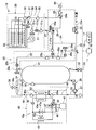
図1は本実施例の給湯システム10の構成を示している。図1に示すように、給湯システム10は、貯湯ユニット20と、HP熱源ユニット40と、ガス熱源ユニット50と、コントローラ11を備えている。
図1は本実施例の給湯システム10の構成を示している。図1に示すように、給湯システム10は、貯湯ユニット20と、HP熱源ユニット40と、ガス熱源ユニット50と、コントローラ11を備えている。
HP熱源ユニット40は、圧縮機41と、凝縮器である第1熱交換器43と、膨張弁44と、蒸発器である第2熱交換器45を備えるヒートポンプ40aを備えている。ヒートポンプ40aでは、圧縮機41の吐出側と四方弁42と第1熱交換器43の冷媒流路43aと膨張弁44と第2熱交換器45と四方弁42と圧縮機41の吸入側が、冷媒配管46によって順に接続されており、冷媒がこの順に循環する。冷媒は、例えばR744(CO2冷媒)であってもよいし、R410A(HFC冷媒)であってもよい。第1熱交換器43は、冷媒流路43aと循環水流路43bとを備えている。第2熱交換器45の近傍にはファン45aが設置されている。第2熱交換器45は、ファン45aによって送られる外気と冷媒との間で熱交換を行う。冷媒配管46には、圧縮機41の吐出側と四方弁42との間と、膨張弁44と第2熱交換器45との間に、除霜経路47が接続されている。除霜経路47には、除霜弁47aが設けられている。
第1熱交換器43の循環水流路43bの入口側には循環往路接続経路48が接続されており、出口側には循環復路接続経路49が接続されている。循環往路接続経路48には、入口側サーミスタ48aが設けられており、循環復路接続経路49には出口側サーミスタ49aが設けられている。入口側サーミスタ48aは、第1熱交換器43の循環水流路43bに流入する循環水の温度を検出し、出口側サーミスタ49aは、第1熱交換器43の循環水流路43bから流出する循環水の温度を検出する。なお実際には、各サーミスタ48a,49aは水温に応じた検出信号を出力し、この信号がコントローラ11に入力されることにより水温が検出される。以下においても、サーミスタやセンサが検出するという表現は、実際には、これらの検出信号がコントローラ11に入力されることにより温度や水の流量を検出することを意味する。
貯湯ユニット20は、貯湯槽21と混合器24とを備えている。貯湯槽21の底部には、貯湯槽21に水道水を給水する給水経路22が接続されている。給水経路22の水道水入口22aの近傍には、減圧弁23が設けられている。減圧弁23は、給水経路22への給水圧力を調整する。給水経路22の減圧弁23より下流側には、混合器24の混合給水経路26が接続されている。混合給水経路26には、給水制御弁26aと、給水流量センサ26bと、給水サーミスタ26cが設けられている。給水制御弁26aは、混合給水経路26を流れる水道水の流量を調整する。給水流量センサ26bと給水サーミスタ26cは、混合給水経路26を流れる水道水の流量及び温度を検出する。貯湯槽21内の温水が減少したり、給水制御弁26aが開いたりすると、減圧弁23の下流側圧力が低下する。減圧弁23は、下流側圧力が低下すると開き、その圧力を所定の調圧値に維持しようとする。このため、貯湯槽21内の温水が減少したり、混合器24の給水制御弁26aが開いたりすると、これらに水道水が給水される。
給水経路22において、混合給水経路26の接続部よりも下流側には、排水経路31が接続されている。排水経路31の途中には、排水弁32が設けられている。排水弁32は手動で開閉することができる。排水弁32を開くと、貯湯槽21内の水が排水経路31を通じて外部に排水される。
貯湯槽21の底部には、循環往路33の一端が接続されており、貯湯槽21の上部には、循環復路34の一端が接続されている。循環往路33の他端は、HP熱源ユニット40の循環往路接続経路48に接続されており、循環復路34の他端は、循環復路接続経路49に接続されている。循環往路33には、往路サーミスタ36と循環ポンプ37とが設けられている。往路サーミスタ36は、貯湯槽21から循環往路33に流出した水の温度を検出する。循環ポンプ37が駆動すると、貯湯槽21の下部から循環往路33に水が吸出され、この水が第1熱交換器43の循環水流路43bを流れて、循環復路34を通じて貯湯槽21の上部に戻される。このようにして、貯湯槽21とヒートポンプ40aとの間の循環経路が構成されている。
タンクユニット20の内部の循環復路34には、電気式の凍結防止ヒータ34aが設けられている。循環復路34の途中には、圧力開放経路38が接続されており、圧力開放経路38には、リリーフ弁38aが設けられている。リリーフ弁38aの開弁圧力は、減圧弁23の調圧値よりも僅かに大きく設定されている。減圧弁23の調圧が不能になった場合には、リリーフ弁38aが開き、貯湯槽21内の圧力が耐圧可能な圧力を超えるのを防止する。貯湯槽21では、その上端から所定量(例えば30リットル)の箇所に上部サーミスタ39が取り付けられている。上部サーミスタ39は、貯湯槽21上部の水温を検出する。なお、貯湯ユニット20には、外気温度を検出する外気温サーミスタ35も設けられている。
貯湯槽21の上部には、混合器24の温水経路25が接続されている。温水経路25には、温水制御弁25aと、温水流量センサ25bと、温水サーミスタ25cが設けられている。温水制御弁25aは、貯湯槽21から温水経路25へ流れる水の流量を調整する。温水流量センサ25bは、貯湯槽21から温水経路25へ流れる水の流量を検出する。温水サーミスタ25cは、温水経路25を流れる水の温度を検出する。温水経路25と混合給水経路26とは合流して第1混合経路27に接続されている。第1混合経路27には、第1混合経路27を流れる混合水の温度を検出する混合サーミスタ27aが設けられている。
貯湯ユニット20は、第1給湯経路29を備えている。第1給湯経路29には、給湯サーミスタ29aが設けられている。第1給湯経路29の先端には、給湯栓60が接続されている。給湯栓60は、浴室、洗面所、台所等に配置されている(図1では、これら複数の給湯栓60を1つで代表している)。第1混合経路27の途中と第1給湯経路29の途中は、給湯バイパス経路28によって接続されている。給湯バイパス経路28には、バイパス制御弁28aが設けられている。バイパス制御弁28aを開いた状態では、第1混合経路27を流れた混合水が給湯バイパス経路28へ流れ、バイパス制御弁28aを閉じた状態では、第1混合経路27を流れた混合水が、後記するガス熱源ユニット50の第2混合経路51へ流れる。
ガス熱源ユニット50は、バーナ熱交換器52とバーナ53等を備えている。バーナ熱交換器52には、第2混合経路51を介して、貯湯ユニット20の第1混合経路27からの混合水が流入する。第2混合経路51には、入水サーミスタ51aと給湯流量センサ51bと水量サーボ51cとが設けられている。入水サーミスタ51aと給湯流量センサ51bは、それぞれ第2混合経路51を流れる水の温度及び流量を検出する。水量サーボ51cは、第2混合経路51を流れる水の流量を調整する。ガス燃焼式のバーナ53は、バーナ熱交換器52を加熱する。バーナ熱交換器52で加熱された水は、第2給湯経路54を介して、貯湯ユニット20の第1給湯経路29に流れ込む。第2給湯経路54には、バーナ熱交換器52の出口近傍に、缶体サーミスタ55が設けられており、その下流側に出湯サーミスタ56が設けられている。第2混合経路51における水量サーボ51cの下流側と、第2給湯経路54の缶体サーミスタ55と出湯サーミスタ56との間には、熱源機バイパス経路57が接続されている。第2混合経路51と熱源機バイパス経路57との接続部には、熱源機バイパス制御弁58が設けられている。熱源機バイパス制御弁58の開度を調整することによって、第2混合経路51を流れる水の一部が熱源機バイパス経路57に流れ、その水の流量が調整される。
コントローラ11は、CPU、ROM、RAM等を備えている。ROMには各種の運転プログラムが格納されている。RAMには、コントローラ11に入力される各種信号や、CPUが処理を実行する過程で生成される種々のデータが一時的に記憶される。詳細には、RAMには、上記した各種のサーミスタ25c,26c,27a,29a,35,36,39,48a,49a,51a,55,56及び流量センサ25b,26b,51bの検出信号が入力され、これらの情報が一時的に記憶される。コントローラ11では、CPUがROMやRAMに記憶された情報に基づいて、貯湯ユニット20、HP熱源ユニット40およびガス熱源ユニット50の各種機器に対して駆動信号を出力する。また、コントローラ11には、リモコン13が接続されている。リモコン13には、給湯システム10を操作するためのスイッチ16、給湯システム10の動作状態を表示する液晶表示器17等が設けられており、リモコン13で設定された情報がコントローラ11に入力される。
(蓄熱運転)
給湯システム10では、ヒートポンプ40aによって貯湯槽21の水を加熱して高温の温水とし、この温水を貯湯槽21に貯湯する蓄熱運転を実行可能である。
給湯システム10では、ヒートポンプ40aによって貯湯槽21の水を加熱して高温の温水とし、この温水を貯湯槽21に貯湯する蓄熱運転を実行可能である。
蓄熱運転では、HP熱源ユニット40において、圧縮機41を駆動する。圧縮機41で圧縮された冷媒が、第1熱交換器43の冷媒流路43aを流れる際に循環水流路43bを流れる循環水を加熱する。冷媒流路43aから流出した冷媒は、膨張弁44で膨張して冷却され、第2熱交換器45を流れる際に外気から吸熱して昇温する。昇温した冷媒が圧縮機41に流入して再び圧縮されることによってさらに昇温する。
貯湯ユニット20では、循環ポンプ37が作動し、貯湯槽21内の水が貯湯槽21の底部から循環往路33に吸出される。循環往路33に吸出された水は、HP熱源ユニット40の第1熱交換器43の循環水流路43bを通過する際に加熱されて温度上昇する。温度上昇した温水は、循環復路34を流れて貯湯槽21の上部に戻される。この循環が行われることによって、貯湯槽21では、低温層の上部に高温層が積層した温度成層が形成される。貯湯槽21に高温の温水が戻され続けると、高温層の厚さ(深さ)は次第に大きくなり、最大限に蓄熱された状態では、貯湯槽21の全体に高温の温水が貯まった状態になる。貯湯槽21に温度成層が形成されていると、貯湯槽21に最大限に蓄熱が行われていなくても、貯湯槽21の上部に接続されている温水経路25に高温の温水を送り出すことが可能となる。
(給湯運転)
給湯運転では、混合器24で給湯設定温度に調整された混合水を給湯バイパス経路28を通じて給湯栓60から給湯する第1給湯運転と、混合器24で給湯設定温度よりも低い温度に調整された混合水をガス熱源ユニット50で加熱して給湯栓60から給湯する第2給湯運転のいずれかを実行する。
給湯運転では、混合器24で給湯設定温度に調整された混合水を給湯バイパス経路28を通じて給湯栓60から給湯する第1給湯運転と、混合器24で給湯設定温度よりも低い温度に調整された混合水をガス熱源ユニット50で加熱して給湯栓60から給湯する第2給湯運転のいずれかを実行する。
貯湯槽21の上部サーミスタ39の検出水温が、リモコン13で設定されている給湯設定温度よりも高い第1基準温度(例えば給湯設定温度+5℃)以上である場合には、第1給湯運転が行われる。第1給湯運転では、コントローラ11がバイパス制御弁28aを開状態とし、水量サーボ51cを全閉状態とする。コントローラ11は、混合サーミスタ27aで検出される水温が給湯設定温度となるように、温水制御弁25aの開度と給水制御弁26aの開度を調整する。給湯設定温度に調整された混合水は、第1混合経路27を流れた後に、給湯バイパス経路28及び第1給湯経路29を通じて給湯栓60から給湯される。
一方、上部サーミスタ39の検出水温が第1基準温度未満である場合には、第2給湯運転が行われる。第2給湯運転では、コントローラ11が、バイパス制御弁28aを全閉状態とし、水量サーボ51cを所定開度に設定する。コントローラ11は、混合サーミスタ27aで検出される水温が給湯設定温度よりも低い第2基準温度(例えば給湯設定温度-5℃)となるように、温水制御弁25aの開度と給水制御弁26aの開度を調整する。第2基準温度に調整された混合水は、第1混合経路27を流れ、ガス熱源ユニット50の第2混合経路51を流れてバーナ熱交換器52に流入し、バーナ53により加熱される。バーナ53の加熱能力は、バーナ熱交換器52の出口に設けられている缶体サーミスタ55で検出される水温が60℃以上となるように制御される。これにより、配管に結露水が発生することを抑制することができる。第2混合経路51を流れる混合水の一部が熱源機バイパス経路57を通じて第2給湯経路54に流入し、バーナ熱交換器52からの60℃以上の水と熱源機バイパス経路57からの第2基準温度の水とが混合されて、給湯設定温度の水が第1給湯経路29に送られる。このようにして、給湯設定温度に調温された水が、第1給湯経路29を通じて給湯栓60から給湯される。これにより、第1給湯運転中に貯湯槽21に貯湯しておいた温水を消費しつくした場合にも、給湯設定温度に調温された温水を給湯し続けることができる。
(除霜運転)
冬季などの外気温が低い状態でヒートポンプ40aを駆動すると、第2熱交換器45に着霜してしまうことがある。第2熱交換器45に着霜してしまうと、外気との間の熱交換効率が低下して、ヒートポンプ40aでの循環水の加熱能力が低下してしまう。そこで、本実施例の給湯システム10では、第2熱交換器45に着霜した場合に、第2熱交換器45から除霜する除霜運転を実行可能である。除霜運転では、HP熱源ユニット40において、除霜弁47aを開いた状態で圧縮機41を駆動する。これによって、図1の破線矢印に示すように、圧縮機41から吐出した高温の冷媒は、除霜経路47を通じて第2熱交換器45に流れて、圧縮機41に戻るように循環する。高温の冷媒が第2熱交換器45を流れることで、第2熱交換器45から除霜することができる。
冬季などの外気温が低い状態でヒートポンプ40aを駆動すると、第2熱交換器45に着霜してしまうことがある。第2熱交換器45に着霜してしまうと、外気との間の熱交換効率が低下して、ヒートポンプ40aでの循環水の加熱能力が低下してしまう。そこで、本実施例の給湯システム10では、第2熱交換器45に着霜した場合に、第2熱交換器45から除霜する除霜運転を実行可能である。除霜運転では、HP熱源ユニット40において、除霜弁47aを開いた状態で圧縮機41を駆動する。これによって、図1の破線矢印に示すように、圧縮機41から吐出した高温の冷媒は、除霜経路47を通じて第2熱交換器45に流れて、圧縮機41に戻るように循環する。高温の冷媒が第2熱交換器45を流れることで、第2熱交換器45から除霜することができる。
(凍結防止運転)
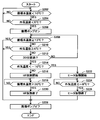
冬季などの外気温が低い状態で、蓄熱運転を行わないまま長時間が経過すると、第1熱交換器43の循環水流路43bや、循環往路33、循環往路接続経路48、循環復路接続経路49、循環復路34の内部に循環水が滞留し、これらの配管の内部で循環水が凍結してしまうことがある。循環水が凍結してしまうと、凍結した循環水が溶融するまで、蓄熱運転を実行できなくなってしまう。そこで、本実施例の給湯システム10では、外気温度が低く、循環水の温度が低下した場合に、循環水の凍結を防止する凍結防止運転を実行可能である。以下では図2を参照しながら、給湯システム10が行う凍結防止運転について説明する。
冬季などの外気温が低い状態で、蓄熱運転を行わないまま長時間が経過すると、第1熱交換器43の循環水流路43bや、循環往路33、循環往路接続経路48、循環復路接続経路49、循環復路34の内部に循環水が滞留し、これらの配管の内部で循環水が凍結してしまうことがある。循環水が凍結してしまうと、凍結した循環水が溶融するまで、蓄熱運転を実行できなくなってしまう。そこで、本実施例の給湯システム10では、外気温度が低く、循環水の温度が低下した場合に、循環水の凍結を防止する凍結防止運転を実行可能である。以下では図2を参照しながら、給湯システム10が行う凍結防止運転について説明する。
ステップS202では、循環水の温度が所定温度(例えば10℃)を下回るか否かを判断する。なお、以下の説明において、循環水の温度とは、往路サーミスタ36で検出される循環往路33内の循環水の温度と、入口側サーミスタ48aで検出される循環往路接続経路48内の循環水の温度のうち、低い方の温度を意味する。循環水の温度が所定温度以上の場合(ステップS202でNOの場合)、処理はステップS202へ戻る。循環水の温度が所定温度を下回ると(ステップS202でYESとなると)、処理はステップS204へ進む。
ステップS204では、外気温サーミスタ35で検出される外気温度が所定温度(例えば5℃)を下回るか否かを判断する。外気温度が所定温度以上の場合(ステップS204でNOの場合)、処理はステップS202へ戻る。外気温度が所定温度を下回ると(ステップS204でYESとなると)、処理はステップS206へ進む。
ステップS206では、循環ポンプ37を駆動する。これによって、貯湯槽21の下部から循環水が吸い出されて、循環往路33、循環往路接続経路48、第1熱交換器43の循環水流路43b、循環復路接続経路49、循環復路34を順に経由して、貯湯槽21の上部に循環水が戻される。このような循環水の流動により、循環往路33、循環往路接続経路48、第1熱交換器43の循環水流路43b、循環復路接続経路49、循環復路34の内部の循環水が置換される。
ステップS208では、循環水の温度(往路サーミスタ36で検出される循環往路33内の循環水の温度と、入口側サーミスタ48aで検出される循環往路接続経路48内の循環水の温度のうち、低い方の温度)が所定温度(例えば13℃)以上であるか否かを判断する。ステップS206で凍結防止運転を開始した時点で、貯湯槽21に余熱が残っている場合には、循環ポンプ37の駆動によって、循環往路33、循環往路接続経路48、第1熱交換器43の循環水流路43b、循環復路接続経路49、循環復路34の内部の循環水が、貯湯槽21からの暖かい循環水で置換される。この場合には、それ以上凍結防止運転を継続する必要がない。従って、ステップS208で循環水の温度が所定温度以上となると(YESとなると)、処理はステップS228へ進んで、循環ポンプ37を停止して、凍結防止運転を終了する。ステップS208で循環水の温度が所定温度に満たない場合(NOの場合)、処理はステップS210へ進む。
ステップS210では、外気温度が所定温度(例えば6℃)以上であるか否かを判断する。ステップS206で凍結防止運転を開始した後に、循環水が凍結するおそれのない温度まで外気温度が上昇した場合には、それ以上凍結防止運転を継続する必要がない。従って、ステップS210で外気温度が所定温度以上となると(YESとなると)、処理はステップS228へ進んで、循環ポンプ37を停止して、凍結防止運転を終了する。ステップS210で外気温度が所定温度に満たない場合(NOの場合)、処理はステップS212へ進む。
ステップS212では、ステップS206で循環ポンプ37を駆動してから所定時間(例えば30分)が経過したか否かを判断する。所定時間が経過していない場合(ステップS212でNOの場合)、処理はステップS208へ戻る。所定時間が経過した場合(ステップS212でYESの場合)、処理はステップS214へ進む。ステップS212からステップS214へ進むのは、循環ポンプ37を駆動してから所定時間が経過するまで、循環水の温度が所定温度に満たない(すなわち、貯湯槽21に余熱が残っていない)場合で、かつ外気温度が上昇もしない場合である。このような場合に、本実施例の給湯システム10では、ステップS214以降の処理で、循環水を加熱する。
ステップS214では、外気温度が所定温度(例えば-10℃)を下回るか否かを判断する。一般的に、ヒートポンプ40aによる循環水の加熱はエネルギー効率が高いため、凍結防止のための循環水の加熱もヒートポンプ40aを駆動して行うことが好ましい。しかしながら、外気温度が低い状況でヒートポンプ40aによる加熱を行うと、第2熱交換器45に着霜してしまうおそれがある。第2熱交換器45に着霜してしまうと、除霜運転に伴ってドレンが発生するため、ドレンの凍結を防止するための処置が別途必要となる。このため、第2熱交換器45には、可能な限り着霜させないことが好ましい。そこで、本実施例の給湯システム10では、凍結防止運転において循環水を加熱する際に、外気温度に応じて加熱手段を切り替える。
ステップS214で外気温度が所定温度以上の場合(NOの場合)、処理はステップS216へ進む。ステップS216では、圧縮機41を駆動してヒートポンプ40aによる循環水の加熱を開始する。ステップS218では、循環水の温度(往路サーミスタ36で検出される循環往路33内の循環水の温度と、入口側サーミスタ48aで検出される循環往路接続経路48内の循環水の温度のうち、低い方の温度)が所定温度(例えば30℃)以上となるまで待機する。ステップS218で循環水の温度が所定温度以上となると(YESとなると)、ステップS220で圧縮機41を停止してヒートポンプ40aによる循環水の加熱を終了する。その後、処理はステップS228へ移行し、循環ポンプ37を停止して、凍結防止運転を終了する。
ステップS214で外気温度が所定温度を超えている場合(NOの場合)、処理はステップS222へ進む。ステップS222では、凍結防止ヒータ34aをオンして、凍結防止ヒータ34aによる循環水の加熱を開始する。ステップS224では、外気温度が所定温度(例えば-8℃)以上となるまで待機する。ステップS224で外気温度が所定温度以上となると(YESとなると)、ステップS226で凍結防止ヒータ34aをオフして、凍結防止ヒータ34aによる循環水の加熱を終了する。その後、処理はステップS228へ移行し、循環ポンプ37を停止して、凍結防止運転を終了する。
以上のように、本実施例の給湯システム10では、凍結防止運転を行う際に、外気温度が高い場合にはヒートポンプ40aによって循環水を加熱し、外気温度が低い場合には凍結防止ヒータ34aによって循環水を加熱する。このような構成とすることによって、凍結防止運転に起因してヒートポンプ40aの第2熱交換器45に着霜してしまう事態を防ぐことができる。
上記の給湯システム10では、凍結防止ヒータ34aを、HP熱源ユニット40の内部ではなく、貯湯ユニット20の内部に設けている。このような構成とすることで、HP熱源ユニット40内のサーミスタ(循環水の温度を検出する入口側サーミスタ48a、出口側サーミスタ49aおよび冷媒の温度を検出する図示しないサーミスタ)の検出値が凍結防止ヒータ34aからの放熱の影響を受けることを防ぐことができる。
なお、上記の給湯システム10では、凍結防止運転に限らず、蓄熱運転においても、外気温度が所定温度(例えば-10℃)を下回る場合には、ヒートポンプ40aによる循環水の加熱を行わないようにして、第2熱交換器45への着霜を防ぐ構成としてもよい。このような構成とした場合でも、上記の給湯システム10によれば、ガス熱源ユニット50を用いる第2給湯運転によって、給湯栓60に給湯設定温度の水を供給することができる。使用者の利便性を損なうことなく、ヒートポンプ40aの第2熱交換器45への着霜を防ぐことができる。
上記の給湯システム10では、凍結防止ヒータ34aを、循環往路33ではなく、循環復路34に設けている。このような構成とすることで、往路サーミスタ36の検出値が凍結防止ヒータ34aからの放熱の影響を受けることを防ぐことができる。
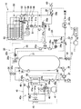
なお、図3に示すように、凍結防止ヒータ34aをHP熱源ユニット40の内部の循環往路接続経路48に設ける構成とした場合でも、図2のような凍結防止運転を行うことによって、凍結防止運転に起因してヒートポンプ40aの第2熱交換器45に着霜してしまう事態を防ぐことができる。
上記の実施例では、ヒートポンプ40aと貯湯槽21の間で循環させる熱媒として、給湯で供給する水道水(上水)を使用する構成について説明した。これとは異なり、例えばヒートポンプ40aと貯湯槽21の間で循環させる熱媒として不凍液を使用し、給湯で供給する水道水(上水)と貯湯槽21に貯められた不凍液の間で熱交換する熱交換器を別途設けることで、貯湯槽21の蓄熱を給湯に利用する構成としてもよい。
上記の実施例では、貯湯槽21に貯めた熱媒を給湯に利用する構成について説明した。これとは異なり、例えば貯湯槽21に貯めた熱媒を床暖房や浴室乾燥暖房機などの暖房に利用する構成としてもよい。あるいは、貯湯槽21に貯めた熱媒を給湯と暖房の両方に利用する構成としてもよい。
以上、本発明の具体例を詳細に説明したが、これらは例示にすぎず、特許請求の範囲を限定するものではない。特許請求の範囲に記載の技術には、以上に例示した具体例を様々に変形、変更したものが含まれる。また、本明細書または図面に説明した技術要素は、単独であるいは各種の組合せによって技術的有用性を発揮するものであり、出願時の請求項記載の組合せに限定されるものではない。また、本明細書または図面に例示した技術は、複数目的を同時に達成するものであり、そのうちの一つの目的を達成すること自体で技術的有用性を持つものである。
Claims (3)
- 外気から吸熱して熱媒を加熱するヒートポンプを備えるヒートポンプユニットと、
熱媒を蓄えるタンクを備えるタンクユニットと、
熱媒を加熱する補助熱源ユニットを備えるヒートポンプシステムであって、
外気温度を検出する外気温度検出手段と、
タンクとヒートポンプの間で熱媒が流れる流路に設けられたヒータをさらに備えており、
熱媒の凍結を防ぐために、タンクとヒートポンプの間で熱媒を循環させながら加熱する凍結防止運転を実行可能であり、
凍結防止運転において、外気温度が高い場合に、ヒートポンプによって熱媒を加熱し、外気温度が低い場合に、ヒータによって熱媒を加熱する、ヒートポンプシステム。 - タンクユニットの内部の流路にヒータが設けられている、請求項1のヒートポンプシステム。
- ヒートポンプからタンクへ熱媒が戻る流路にヒータが設けられている、請求項2のヒートポンプシステム。
Priority Applications (2)
| Application Number | Priority Date | Filing Date | Title |
|---|---|---|---|
| KR1020157033035A KR101723419B1 (ko) | 2013-05-22 | 2014-03-10 | 히트펌프 시스템 |
| CN201480029131.0A CN105247293B (zh) | 2013-05-22 | 2014-03-10 | 热泵系统 |
Applications Claiming Priority (2)
| Application Number | Priority Date | Filing Date | Title |
|---|---|---|---|
| JP2013108067A JP5981880B2 (ja) | 2013-05-22 | 2013-05-22 | ヒートポンプシステム |
| JP2013-108067 | 2013-05-22 |
Publications (1)
| Publication Number | Publication Date |
|---|---|
| WO2014188759A1 true WO2014188759A1 (ja) | 2014-11-27 |
Family
ID=51933325
Family Applications (1)
| Application Number | Title | Priority Date | Filing Date |
|---|---|---|---|
| PCT/JP2014/056139 Ceased WO2014188759A1 (ja) | 2013-05-22 | 2014-03-10 | ヒートポンプシステム |
Country Status (4)
| Country | Link |
|---|---|
| JP (1) | JP5981880B2 (ja) |
| KR (1) | KR101723419B1 (ja) |
| CN (1) | CN105247293B (ja) |
| WO (1) | WO2014188759A1 (ja) |
Cited By (3)
| Publication number | Priority date | Publication date | Assignee | Title |
|---|---|---|---|---|
| EP3370012A4 (en) * | 2015-10-30 | 2019-07-10 | GD Midea Heating & Ventilating Equipment Co., Ltd. | FREEZER PROCESS AND SYSTEM FOR FAILURE OF THE FOUR-WAY VALVE OF A HEAT PUMP WATER HEATER |
| EP3521727A4 (en) * | 2016-10-03 | 2019-10-16 | Mitsubishi Electric Corporation | HOT WATER TREATMENT DEVICE FROM THE STORAGE TYPE |
| WO2025012597A1 (en) * | 2023-07-13 | 2025-01-16 | Octopus Energy Heating Limited | Methods and systems and apparatus to support reduced energy and water usage |
Families Citing this family (5)
| Publication number | Priority date | Publication date | Assignee | Title |
|---|---|---|---|---|
| JP6438765B2 (ja) * | 2014-12-26 | 2018-12-19 | リンナイ株式会社 | 熱機器 |
| JP6502722B2 (ja) | 2015-03-30 | 2019-04-17 | リンナイ株式会社 | 給湯システム |
| JP7013854B2 (ja) * | 2017-12-26 | 2022-02-01 | 株式会社ノーリツ | 貯湯給湯装置 |
| JP7482764B2 (ja) | 2020-12-02 | 2024-05-14 | リンナイ株式会社 | ヒートポンプシステム |
| JP7769953B2 (ja) * | 2021-10-05 | 2025-11-14 | パナソニックIpマネジメント株式会社 | 冷凍装置 |
Citations (7)
| Publication number | Priority date | Publication date | Assignee | Title |
|---|---|---|---|---|
| JPS57182071U (ja) * | 1981-05-14 | 1982-11-18 | ||
| JP2002147858A (ja) * | 2000-11-08 | 2002-05-22 | Denso Corp | 凍結防止ヒータ付き給湯装置 |
| JP2006003077A (ja) * | 2005-08-01 | 2006-01-05 | Daikin Ind Ltd | ヒートポンプ式給湯装置 |
| JP2009156495A (ja) * | 2007-12-26 | 2009-07-16 | Corona Corp | ヒートポンプ式給湯機 |
| JP2010133610A (ja) * | 2008-12-03 | 2010-06-17 | Sharp Corp | ヒートポンプ式給湯システム |
| JP2013170788A (ja) * | 2012-02-22 | 2013-09-02 | Toshiba Carrier Corp | 給湯装置 |
| JP2014016105A (ja) * | 2012-07-09 | 2014-01-30 | Rinnai Corp | 給湯暖房システム |
Family Cites Families (7)
| Publication number | Priority date | Publication date | Assignee | Title |
|---|---|---|---|---|
| JP3908668B2 (ja) * | 2003-01-16 | 2007-04-25 | 株式会社コロナ | ヒートポンプ式給湯機 |
| JP2008267790A (ja) * | 2007-03-27 | 2008-11-06 | Daikin Ind Ltd | ヒートポンプ式給湯装置および暖房給湯装置 |
| CN201251284Y (zh) * | 2008-07-28 | 2009-06-03 | 山东桑乐太阳能有限公司 | 一种太阳能热泵热水器 |
| CN201561565U (zh) * | 2009-09-28 | 2010-08-25 | 浙江家得乐太阳能有限公司 | 具有防结霜功能的空气源热泵热水器 |
| JP5461318B2 (ja) * | 2010-06-17 | 2014-04-02 | リンナイ株式会社 | 太陽熱利用給湯システム |
| CN202149598U (zh) * | 2011-06-17 | 2012-02-22 | 博浪热能科技有限公司 | 一种自动防冻结的热泵热水器 |
| CN202177213U (zh) * | 2011-08-01 | 2012-03-28 | 佛山市高明万和电气有限公司 | 辅助加热型热泵热水器 |
-
2013
- 2013-05-22 JP JP2013108067A patent/JP5981880B2/ja active Active
-
2014
- 2014-03-10 CN CN201480029131.0A patent/CN105247293B/zh active Active
- 2014-03-10 KR KR1020157033035A patent/KR101723419B1/ko active Active
- 2014-03-10 WO PCT/JP2014/056139 patent/WO2014188759A1/ja not_active Ceased
Patent Citations (7)
| Publication number | Priority date | Publication date | Assignee | Title |
|---|---|---|---|---|
| JPS57182071U (ja) * | 1981-05-14 | 1982-11-18 | ||
| JP2002147858A (ja) * | 2000-11-08 | 2002-05-22 | Denso Corp | 凍結防止ヒータ付き給湯装置 |
| JP2006003077A (ja) * | 2005-08-01 | 2006-01-05 | Daikin Ind Ltd | ヒートポンプ式給湯装置 |
| JP2009156495A (ja) * | 2007-12-26 | 2009-07-16 | Corona Corp | ヒートポンプ式給湯機 |
| JP2010133610A (ja) * | 2008-12-03 | 2010-06-17 | Sharp Corp | ヒートポンプ式給湯システム |
| JP2013170788A (ja) * | 2012-02-22 | 2013-09-02 | Toshiba Carrier Corp | 給湯装置 |
| JP2014016105A (ja) * | 2012-07-09 | 2014-01-30 | Rinnai Corp | 給湯暖房システム |
Cited By (4)
| Publication number | Priority date | Publication date | Assignee | Title |
|---|---|---|---|---|
| EP3370012A4 (en) * | 2015-10-30 | 2019-07-10 | GD Midea Heating & Ventilating Equipment Co., Ltd. | FREEZER PROCESS AND SYSTEM FOR FAILURE OF THE FOUR-WAY VALVE OF A HEAT PUMP WATER HEATER |
| US10557645B2 (en) | 2015-10-30 | 2020-02-11 | Gd Midea Heating & Ventilating Equipment Co., Ltd. | Method and system for preventing freezing when four-way valve in heat pump water heater is failed, and heat pump water heater |
| EP3521727A4 (en) * | 2016-10-03 | 2019-10-16 | Mitsubishi Electric Corporation | HOT WATER TREATMENT DEVICE FROM THE STORAGE TYPE |
| WO2025012597A1 (en) * | 2023-07-13 | 2025-01-16 | Octopus Energy Heating Limited | Methods and systems and apparatus to support reduced energy and water usage |
Also Published As
| Publication number | Publication date |
|---|---|
| KR20150143845A (ko) | 2015-12-23 |
| CN105247293B (zh) | 2019-04-05 |
| CN105247293A (zh) | 2016-01-13 |
| JP2014228193A (ja) | 2014-12-08 |
| JP5981880B2 (ja) | 2016-08-31 |
| KR101723419B1 (ko) | 2017-04-05 |
Similar Documents
| Publication | Publication Date | Title |
|---|---|---|
| JP5981880B2 (ja) | ヒートポンプシステム | |
| JP2008232576A (ja) | 給湯装置 | |
| CN102620459B (zh) | 制冷循环装置和使用该制冷循环装置的热水供暖装置 | |
| JP2003214700A (ja) | ヒートポンプ式給湯装置 | |
| JP5592427B2 (ja) | 暖房システム | |
| WO2016059837A1 (ja) | ヒートポンプ式暖房装置 | |
| JP5597669B2 (ja) | 熱機器 | |
| JP2002048399A (ja) | ヒートポンプ式給湯装置 | |
| JP5764533B2 (ja) | 給湯暖房システム | |
| EP2933579B1 (en) | Heat pump water heater | |
| JP5866226B2 (ja) | 給湯装置 | |
| JP5176474B2 (ja) | ヒートポンプ給湯装置 | |
| JP5899344B2 (ja) | ヒートポンプシステム | |
| JP2010054145A (ja) | ヒートポンプ給湯機 | |
| JP6327499B2 (ja) | ヒートポンプ給湯装置 | |
| KR101343445B1 (ko) | 하이브리드식 급탕 장치 | |
| JP7482764B2 (ja) | ヒートポンプシステム | |
| JP6094363B2 (ja) | 給湯装置 | |
| JP2006003077A (ja) | ヒートポンプ式給湯装置 | |
| JP5986455B2 (ja) | 貯湯式給湯機 | |
| JP6152689B2 (ja) | ヒートポンプ給湯装置 | |
| JP6138285B2 (ja) | ヒートポンプ給湯器システム | |
| JP5887192B2 (ja) | 給湯器 | |
| KR20150081947A (ko) | 급탕 난방장치 | |
| JP2007285571A (ja) | ヒートポンプ装置 |
Legal Events
| Date | Code | Title | Description |
|---|---|---|---|
| 121 | Ep: the epo has been informed by wipo that ep was designated in this application |
Ref document number: 14800580 Country of ref document: EP Kind code of ref document: A1 |
|
| ENP | Entry into the national phase |
Ref document number: 20157033035 Country of ref document: KR Kind code of ref document: A |
|
| NENP | Non-entry into the national phase |
Ref country code: DE |
|
| 122 | Ep: pct application non-entry in european phase |
Ref document number: 14800580 Country of ref document: EP Kind code of ref document: A1 |