WO2014185514A1 - 成形機における射出装置 - Google Patents
成形機における射出装置 Download PDFInfo
- Publication number
- WO2014185514A1 WO2014185514A1 PCT/JP2014/063050 JP2014063050W WO2014185514A1 WO 2014185514 A1 WO2014185514 A1 WO 2014185514A1 JP 2014063050 W JP2014063050 W JP 2014063050W WO 2014185514 A1 WO2014185514 A1 WO 2014185514A1
- Authority
- WO
- WIPO (PCT)
- Prior art keywords
- melter
- melting
- cylinder
- opening
- injection
- Prior art date
Links
Images


Classifications
-
- B—PERFORMING OPERATIONS; TRANSPORTING
- B29—WORKING OF PLASTICS; WORKING OF SUBSTANCES IN A PLASTIC STATE IN GENERAL
- B29C—SHAPING OR JOINING OF PLASTICS; SHAPING OF MATERIAL IN A PLASTIC STATE, NOT OTHERWISE PROVIDED FOR; AFTER-TREATMENT OF THE SHAPED PRODUCTS, e.g. REPAIRING
- B29C45/00—Injection moulding, i.e. forcing the required volume of moulding material through a nozzle into a closed mould; Apparatus therefor
- B29C45/17—Component parts, details or accessories; Auxiliary operations
- B29C45/46—Means for plasticising or homogenising the moulding material or forcing it into the mould
- B29C45/58—Details
- B29C45/586—Injection or transfer plungers
-
- B—PERFORMING OPERATIONS; TRANSPORTING
- B29—WORKING OF PLASTICS; WORKING OF SUBSTANCES IN A PLASTIC STATE IN GENERAL
- B29C—SHAPING OR JOINING OF PLASTICS; SHAPING OF MATERIAL IN A PLASTIC STATE, NOT OTHERWISE PROVIDED FOR; AFTER-TREATMENT OF THE SHAPED PRODUCTS, e.g. REPAIRING
- B29C45/00—Injection moulding, i.e. forcing the required volume of moulding material through a nozzle into a closed mould; Apparatus therefor
- B29C45/17—Component parts, details or accessories; Auxiliary operations
- B29C45/46—Means for plasticising or homogenising the moulding material or forcing it into the mould
- B29C45/53—Means for plasticising or homogenising the moulding material or forcing it into the mould using injection ram or piston
-
- B—PERFORMING OPERATIONS; TRANSPORTING
- B29—WORKING OF PLASTICS; WORKING OF SUBSTANCES IN A PLASTIC STATE IN GENERAL
- B29C—SHAPING OR JOINING OF PLASTICS; SHAPING OF MATERIAL IN A PLASTIC STATE, NOT OTHERWISE PROVIDED FOR; AFTER-TREATMENT OF THE SHAPED PRODUCTS, e.g. REPAIRING
- B29C45/00—Injection moulding, i.e. forcing the required volume of moulding material through a nozzle into a closed mould; Apparatus therefor
- B29C45/17—Component parts, details or accessories; Auxiliary operations
- B29C45/72—Heating or cooling
- B29C45/74—Heating or cooling of the injection unit
Definitions
- the present invention by reciprocating a heated melter, it is separated into a resin melting process and a resin injection process for a large number of plastic pellets, and a sufficient time for melting the resin is secured.
- the present invention relates to an injection apparatus in a molding machine that can perform the injection process of the molten resin very quickly and efficiently in a short time.
- screw type and plunger type injection devices there are screw type and plunger type injection devices.
- each is mainly composed of a cylinder and a screw.
- the pellets introduced from the hopper provided in the cylinder are transferred to the injection nozzle side by the rotation of the screw inside the cylinder, and are heated and melted in the transfer process. Then, the molten resin is collected at the tip of the nozzle, injected, and the molten resin is sent to the mold.
- pellets are made of plastic (synthetic resin) and have a thermal conductivity of about 0.07 to 0.20 kcal / m ⁇ hr ⁇ ° C. This is one-hundredth to several-thousandth of the thermal conductivity of the metal, and thus, the pellet can be said to be a substantially heat insulating material. Therefore, even when sufficient heat of fusion is applied to melt the pellet, it is difficult for the heat to be transferred to the inside (center) of the pellet, and it takes a considerable time to be sufficiently heated.
- the pellets have to be melted for a relatively long time in the cylinder, and the working efficiency is not good.
- the solids of the many pellets charged in the cylinder are heated and moved to the injection side by rotating the screw, and at this time, a part of the many pellets is moved to the inner wall of the cylinder. It will be in a state of being pressed.
- the amount of resin stored in the cylinder is one time. This amount is more than several tens of times the amount required for the injection, and a wasteful amount of pellets remains in the cylinder.
- Patent Document 2 is of the plunger type having the most basic structure, and is mainly composed of a frustoconical heating cylinder having a large number of through holes, an injection plunger, a supply cylinder, and the like. . The synthetic resin raw material is sent out to the heating cylinder by the injection plunger, and injection is performed.
- Patent Document 2 also has various problems.
- the injection plunger and the frustoconical heating cylinder have different diameters, and the diameter of the injection plunger is slightly smaller than the diameter of the facing portion of the heating cylinder. .
- a gap chamber having a volume larger than the area of the tip of the injection plunger exists between the tip of the injection plunger, the heating cylinder, the tip of the injection plunger, and the supply cylinder.
- the molten synthetic resin raw material is once extruded into the gap chamber by the injection plunger, but even if the injection plunger further moves to the heating cylinder side, the synthetic resin raw material efficiently flows into the through hole of the heating cylinder. There is a possibility that it will not flow into the heating cylinder and remain in the gap chamber. And the synthetic resin raw material remaining in the space may be a hindrance to the synthetic resin raw material to be newly sent out to the through hole of the heating cylinder. Moreover, there is a sufficient possibility that the synthetic resin raw material to be newly sent out and the resin that has deteriorated due to remaining for a long time are mixed.
- the present applicant has improved an inconvenient point of such a frustoconical heating cylinder and an injection plunger, and an injection device in a molding machine capable of efficiently performing a pellet resin melting process and a molten resin injection process.
- Patent Document 3 it is possible to provide an epoch-making invention in which pellets can be melted by resin and injection of molten resin can be performed at the same time by simply pressing a pellet aggregate with a plunger.
- the melting step for melting the pellet passes through a large number of conical holes of the heated melter at a predetermined pressure, so that it becomes a molten resin when it exits from the pellet solid. That is, the melting speed and the injection speed are the same in relation to the material of the pellet, the viscosity of the molten resin, the melting temperature, the pressure, the melting speed, the extrusion speed, the flow rate, and the like. Then, although it can be melted fairly quickly in consideration of the melting speed, this time, considering only the injection speed, it was the same time as the melting speed, and it seemed that the injection time was slow.
- JP-A-6-246802 Japanese Patent Publication No. 36-9884 Japanese Patent No. 4880085
- the problem to be solved by the invention is a melting step of melting a resin by passing a plurality of conical holes of a heated melter or holes approximating a conical shape at a predetermined pressure. It is to realize speeding up of the injection process after separating the subsequent injection process of the molten resin. That is, by repeating the melting process and the injection process, the injection process is set regardless of the time of the melting process, thereby dramatically speeding up the injection process.
- an outlet member is provided on the front end injection side in the longitudinal direction, and a closing portion is provided on the rear side.
- the cylinder is provided with a pellet supply port for supplying plastic pellets at an intermediate position between the closing portion and the outlet member, and communicates from the inflow side large opening to the outflow side small opening in the longitudinal direction of the main body.
- Each of the paths is configured as a molten resin injection process, and an open / close valve is interposed in the cylinder between the outlet member and the melter, and the open / close valve is melted in the melter return path process.
- An injection device in a molding machine configured to release the outflow side small opening side of the melter and configured to close the outflow side small opening side of the melter in the forward process of the melter
- the on-off valve is a disc type, and the disc diameter is formed smaller than the melter diameter, and the melter side In the molding machine, wherein when the melter is in the process of injecting the molten resin in the forward path, the melter outlet side small opening hole is blocked by the on-off valve.
- the on-off valve is a disc type, and a plurality of holes are located at an outlet side small opening hole in which the plurality of through holes are formed. And is configured to be constantly elastically pressed toward the melter side, and when the melter is in the process of injecting molten resin in the forward path, the melter is operated by the on-off valve.
- the said subject was solved by having set it as the injection device in the molding machine characterized by closing an outflow side small opening hole.
- the melting hole of the melting device is formed in a conical shape so as to change from the inflow side large opening to the outflow side small opening.
- the above-described problems have been solved by using an injection device in a molding machine.
- the melting hole of the melting device has a large-diameter cylindrical portion as the inflow-side large opening formed close to the end, and the outflow The problem is solved by providing an injection apparatus in a molding machine, wherein the outflow side small opening is formed only on the side.
- the inflow side large opening of the adjacent melt hole is formed in a circular cross section, and the inlet portion of the large inflow side opening is dish-shaped.
- the pellet supply port is provided with a shutter mechanism for opening or closing the pellet supply port.
- a shutter mechanism for opening or closing the pellet supply port.
- the ninth embodiment of the present invention is the injection device in the molding machine according to the eighth embodiment, wherein the set of the melter and the reciprocating rod is arranged in parallel as two sets.
- the problem has been solved.
- a tenth embodiment of the present invention is an injection device in a molding machine according to the eighth embodiment, wherein the set consisting of the melter and the reciprocating rod is arranged in parallel as three or more sets. This solves the problem.
- the heated melter by reciprocating the heated melter, it is separated into a melting step for melting a large number of charged pellets and an injection step for the molten resin, and sufficient time for melting the pellets is ensured.
- the molten resin injection process is extremely quick and efficient in a short time.
- the melter body since the melter body operates like a plunger, the melting process and the injection process can be realized by the reciprocating motion without the plunger of another member that the applicant has conventionally required. Is obtained.
- the outflow side small opening side surface of the melter serves as a pressing surface of the plunger, and the molten resin accumulated in the cylinder on the outflow side small opening side surface of the melter is once With this pressing, there is an advantage that it can be ejected to the outside through the nozzle part quickly and quickly.
- the resin pellets into a large number of plastic pellets and a molten resin injection process, it is possible to secure a sufficient time for good resin melting. It can handle even speed, and can be injected efficiently in a short time.
- the melting device itself is heated to the melting temperature of the pellets by heating means, and the pellets melt.
- the entire periphery of the pellet is in a state surrounded by the inner peripheral wall surface of the melting hole, and the pellet can be melted from the outer periphery to the center part in a substantially even balance.
- the container body since the pellet body moves in the melting hole from the inflow side large opening toward the outflow side small opening, the container body has a large heat capacity. Can be maintained at a sufficient melting temperature while heating the pellets without being affected by the temperature of the molten pellets.
- the pellets are melted substantially uniformly from the outer periphery toward the center, they are pressed by a large number of pellets that enter one after the other from the inflow side large opening, and can move to the outflow side small opening of the melt hole. Melting of the pellets progresses, and most of the melted part is passed through approximately the middle in the axial direction (longitudinal direction) of the melt hole. Melting of the surrounding pellets progresses at an accelerated rate with the melting heat of the melter. . In the vicinity of the small opening on the outflow side, the pellets are completely melted at the maximum temperature and can be stored in the cylinder as a molten resin.
- the melting machine has a plurality of constricted melting holes in the main body, and a cylinder is formed in the constricting melting holes heated to the melting temperature by the heating means.
- the pellet group extruded in the pellet storage area of the intrusion from the large opening side inflow side large opening, the pellets melt in a well-balanced manner, and the heat capacity of the melter is large, so that a high temperature state can be maintained, Melting is promoted to increase the melting rate, and the molten resin is stored on the outlet member side.
- the temperature of the resin reaches the maximum at the outflow side small opening by the heating means.
- the optimum temperature required immediately before injection and the maximum temperature can be set, and the resin is not deteriorated by setting the high temperature state to the minimum time, so that high-quality molding is possible. That is, the melter has a structure that can raise the resin to the optimum temperature immediately before injection in the last process in which the resin melts.
- the melter has melting holes in which a large number of conical passages or passages approximating a conical shape are formed in the main body, and these many melting holes extend from the inflow side surface portion to the outflow side surface portion. Can be arranged in a substantially parallel state without converging toward. As a result, the large number of small openings on the outflow side can be evenly arranged without being crowded. Accordingly, the heat capacity of the melter itself can be made sufficiently large, and the volume of the thick portion (solid portion) between the melt holes near the outflow side surface can be secured sufficiently large. The heat capacity can also be increased.
- the melting device when the pellet is moved from the large inflow side opening to the small outflow side opening through the melting hole, once the melting device is heated to a high temperature by the heating means, the high temperature is maintained by the large heat capacity and the melting is performed.
- the obtained pellets can maintain a sufficient melting temperature without lowering the temperature, and a molten resin can be formed from a good quality group of pellets.
- the presence of the on-off valve enables the molten resin to be produced satisfactorily even in the melting process, and in particular, the injection of the molten resin is smooth without any reversal of the molten resin in the melter during the injection process. There is an advantage that can be.
- the second embodiment and the third embodiment have the same effects as the present invention.
- the melting hole of the melting device is such that the large-diameter cylindrical portion as the large inflow side opening is formed close to the end, and the small outflow side opening is formed only on the outflow side.
- To the tip end can be formed and processed with the diameter (diameter) of the cylindrical portion, and the melter can be manufactured at a much lower cost than the conical processing. Even if it is the fusion hole formed in this way, there exists an effect similar to a cone-shaped fusion hole by fusion by heating power, while a pellet is pressed in the back side.
- the inflow side large opening of the adjacent melt hole is formed in a circular shape in cross section, and the inlet portion of the inflow side large opening is formed with a dish-like chamfer, and the adjacent inflow side large opening is Because the part that becomes the boundary between the dish-shaped chamfers is formed as a blade, it is crushed and separated finely at the edge-shaped part of the border between the dish-like chamfers on the adjacent inflow side large opening, so the pellets flow in It becomes easier to enter by the large side opening, and the melting of the pellet can be promoted.
- the pellets supplied from the hopper can be controlled to an appropriate amount, and there is an advantage that these can be worked orderly by melting and injecting the desired melting amount of the pellets.
- a plurality of the melting machines and the reciprocating rods are provided as a set, and therefore, it is suitable for a large mold requiring a large amount of pellets. This is also very suitable when a long workpiece (product) is directly formed by using a die from the injection device to the outlet member.
- the pair of the melting machine and the reciprocating rod is arranged in parallel as two sets, so that it can correspond to a large mold while being relatively small. Can be.
- the combination of the melting machine and the reciprocating rod is arranged in parallel as three or more sets, so that it can correspond to a larger mold. Can be.
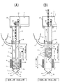
- (A) is a longitudinal side view showing the return path process of the present invention
- (B) is a longitudinal side view showing the forward path process of the present invention
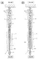
- (A) is a longitudinal side view of the initial position of the melting process of the present invention
- (B) is a longitudinal side view of the intermediate position of the melting process of the present invention
- (C) is a longitudinal side view of the end position of the melting process of the present invention. It is.
- (A) is a main part longitudinal enlarged side view of the initial position of the melting step of the present invention
- (B) and (C) are main part vertical enlarged side views of the intermediate position of the melting process of the present invention
- (D) is the present invention.
- (A) is an enlarged longitudinal side view of a cone-shaped melting hole showing a state in which the pellet moves while melting from the inflow side large opening toward the outflow side small opening
- (B) is the pellet from the inflow side large opening to the outflow side. It is an expansion vertical side view of the fusion hole in which the tip which shows the state moved while melting toward a small opening is narrowed.
- (A) is a vertical side view immediately after the initial position of the injection process of the present invention
- (B) is a vertical side view of an intermediate position of the injection process of the present invention
- (C) is a vertical side view of the end position of the injection process of the present invention.
- FIG. 6A is a cross-sectional view taken along the line X1-X1 in FIG. 5A
- FIG. 5E is a perspective view of another embodiment of the on-off valve.
- (A) is the perspective view which partially cut away the melter in which the cone-shaped fusion hole was formed in square shape
- (B) is the state figure of the site
- (A) is an enlarged vertical side view of the melter and on-off valve location of the second embodiment
- (B) is an enlarged vertical side view of the melter and on-off valve location of the third embodiment.
- (A) is an enlarged longitudinal sectional side view of the melting device and on-off valve location of the fourth embodiment
- (B) is a modification of (A), a partial perspective view of the upper part of the melting device
- (C) ( B) is an enlarged cross-sectional view taken along arrow X2-X2
- (D) is an enlarged cross-sectional view taken along arrow Y1-Y1 of (C).
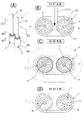
- (A) is a perspective view of a die for producing an H-shaped long product at the outlet member of the injection device of the present invention
- (B) is an enlarged cross-sectional view taken along the line X3-X3 in (A)
- (C) is ( (A) is an enlarged cross-sectional view taken along arrow X4-X4, (D) is an enlarged cross-sectional view taken along arrow X5-X5 in (A), and (E) is an enlarged cross-sectional view taken along arrow X6-X6 in (A).
- FIG. 4C is a longitudinal side view of the present invention
- FIG. 5C is a longitudinal side view of the present invention in a state where the shutter plate of the shutter mechanism in FIG. is there.
- A) is a perspective view schematically showing a state in which two sets of melters and reciprocating rods are arranged in parallel in the injection apparatus of the present invention
- B) is an enlarged cross-sectional view taken along arrow X7-X7 in (A), and (C).
- (A) X8-X8 arrow expanded sectional view of (A)
- (D) is X9-X9 arrow expanded sectional view of (A).
- (A) is a schematic perspective view of a state in which three sets of melters and reciprocating rods are arranged in parallel in the injection apparatus of the present invention
- (B) is an enlarged cross-sectional view taken along arrow X10-X10 in (A)
- (C) is an enlarged cross-sectional view taken along arrow X11-X11
- (D) is an enlarged cross-sectional view taken along arrow X12-X12 in (A).
- the present invention mainly includes a cylinder 1, a melter 2 that melts pellets p, p,..., And drive means 3 that reciprocates the melter 2. And heating means 4.
- An outlet member 5 is provided at the end of the cylinder 1, and the melter 2 and the closing portion 6 that reciprocate are provided therein.
- the closing portion 6 is formed in a plate shape.
- the driving means 3 is provided with a reciprocating rod 34.
- the outlet member 5 is mounted on one end side (lower end in FIG. 1) of the cylinder 1 in the axial direction (or also referred to as the longitudinal direction, and in the vertical direction in FIGS. 1A and 1B).
- the driving means 3 is mounted on the other end side (upper end in FIGS. 1A and 1B) in the axial direction (upper end in the longitudinal direction) via a cylindrical case 13, and the melting means is used by the driving means 3.
- the device 2 is configured to reciprocate (see FIGS. 1 and 2).
- the material of the cylinder 1 needs to be heated quickly, and iron or stainless steel with a high iron content is suitable.
- the cylinder 1 is composed of an elongated cylinder body 11 and a tubular supply pipe 12 connected from a pellet supply port 11a formed near the closing portion 6.
- the supply pipe 12 is configured to communicate with a hopper 8 for storing pellets p, p,.
- the supply pipe 12 is connected by a portion integrated with the cylinder 1 and a pipe formed in an appropriate arc shape.
- the cylinder main body 11 is a cylindrical member, and an inner side of the cylinder main body 11 has a substantially columnar space surrounded by an inner peripheral side surface 11b.
- the thickness of the cylinder body 11 is preferably about 2 mm.
- a large number of pellets p, p,... Can be charged into the hopper 8, and the charged pellets p, p,... Are fed into the cylinder body 11 from the pellet supply port 11a through the supply pipe 12. See FIG. 2A].
- the supply pipe 12 may be provided with a screw conveyance or pneumatic device to forcibly introduce the pellets p, p,.
- the cylinder 1 has a circular cross section, the circle may be slightly deformed to be elliptical. In this case, accurate reciprocation is possible without the melter 2 having the same shape rotating.
- An outlet member 5 such as a nozzle portion 51 or a die 52 is attached to one end side (lower end) of the cylinder body portion 11 in the axial direction (longitudinal direction). As described above, the outlet member 5 includes the nozzle portion 51 and the die 52 (see FIG. 11).
- the nozzle portion 51 is configured to be replaceable so as to change the diameter of the injection portion according to the mold used with the injection device of the present invention.
- the nozzle part 51 includes an injection port 51a and a connection part 51b [see FIG. 1 (A)].
- the injection port 51a is formed to be narrower than the inner diameter of the cylinder body 11, and is a part that is inserted into a gate of a mold (not shown).
- the connection part 51b of the nozzle part 51 and the cylinder body part 11 are detachable with a structure having a screw structure (an outer screw, an inner screw).
- the material of the nozzle part 51 is preferably a material having good thermal conductivity, and specifically, beryllium copper or copper is desirable.
- the die 52 is for manufacturing a long resin product (material).
- the die 52 is attached directly to the cylinder 1 so as to be close to the vicinity of the melter 2 of the cylinder 1 after removing the nozzle portion 51.
- FIG. 52a is formed.
- the specific shape of the forming hole 52a is an “H” shape or the like, but other shapes include an “L” shape, a square, a triangle, a circle, or other polygonal shapes.
- the molding hole 52a is formed as a circular opening on the side where the die 52 is attached to the cylinder 1, and is in a state in which the molten resin q easily flows.
- the forming hole 52a is formed so as to be closer to a desired shape as it goes toward the discharge opening side of the die 52.
- the molding hole 52 a in which the “H” -shaped long resin material is formed, the molding hole 52 a gradually increases from the circular shape toward the outward side from the mounting side to the cylinder 1. It is formed so as to have a shape [see FIGS. 11B to 11E]
- the dice 52 plays a role of manufacturing a long resin shape. That is, long objects having the same cross-sectional shape can be manufactured.
- the melter 2 is formed by forming a large number of melt holes 22, 22,... In a container body portion 21 formed in a substantially cylindrical shape (see FIGS. 1, 5 and 7, etc.).
- the material of the vessel body 21 is preferably a material having a large heat capacity and good heat conduction. Specifically, copper or beryllium copper is used.
- the vessel main body 21 is configured to be reciprocable inside the cylinder main body 11 of the cylinder 1, and is always disposed near the outlet member 5 (see FIG. 1A). .
- the vessel main body 21 of the melter 2 is formed in a cylindrical shape as described above, and a large number of pellets p, p,... Are formed on the side of the vessel main body 21 facing the closing portion 6.
- the surface on the inflow side is referred to as an inflow side surface portion 21a.
- the surface opposite to the inflow side surface portion 21a faces the outlet member 5, and the surface on the side from which the molten resin q flows out is referred to as an outflow side surface portion 21b.
- the outer peripheral side surface of the vessel main body 21 is referred to as a circumferential side surface 21c.
- the vessel body 21 has a cylindrical shape as described above.
- the diameter D2a of the inflow side surface portion 21a and the diameter D2b of the outflow side surface portion 21b are the same as those of the circumferential side surface 21c along the axial direction. It is an exact cylindrical shape having the same diameter (see FIG. 7A). Also, the melting device 2 in FIGS. 1 to 6 has the above exact cylindrical shape.
- the melt hole 22 is formed along the axial direction (longitudinal direction) of the vessel main body 21 (see FIGS. 1 to 6). More specifically, the melt hole 22 is a tunnel-shaped or pipe-shaped conical through-hole [see FIGS. 7B and 7C]. In the melt hole 22, the aforementioned conical through-hole is formed so that the cross-sectional shape at a plurality of arbitrary positions orthogonal to the hole forming direction is changed from a wide shape to a narrow shape. A hole having a gap such as a cone or a pyramid (see FIGS. 7B and 7C and FIGS. 8A and 8B).
- a conical shape is particularly preferable as the conical shape of the melting hole 22, and the diameter is formed so as to gradually decrease from large to small (see FIGS. 7B and 7C).
- the large opening side of the melting hole 22 is referred to as an inflow side large opening 22a into which the pellets p, p,... Flow in (see FIGS. 4A, 4B, 7B, and 7C).
- the small opening side of the melting hole 22 is referred to as an outflow side small opening 22b (see FIGS. 4A, 7B and 7C). That is, the melt hole 22 is a passage that communicates from the inflow side large opening 22a to the outflow side small opening 22b, and the cross section gradually becomes narrower from the inflow side large opening 22a toward the outflow side small opening 22b.
- the inflow side large opening 22a is located in the inflow side part 21a side of the container main body part 21, and faces (or opposes) the said blocking part 6 (refer FIG. 1 (A) and (B)).
- the outflow side small opening 22b is located in the outflow side part 21b, and faces (or opposes) the outlet member 5 (refer FIG. 1 (A) and (B)).
- the inflow side surface portion 21a of the melter 2 is provided with inflow side large openings 22a, 22a,... Of a large number of melting holes 22, 22,. Since the pellets p, p,... Flow into the inflow side large opening 22a facing the plugging portion 6, they are referred to as the inflow side of the melter 2.
- the outflow side surface 21b of the melter 2 is provided with outflow side small openings 22b, 22b,... Of a large number of melting holes 22, 22,.
- the molten resin q in which the pellets p, p,... Are melted out from the outflow side small opening 22b facing the 5 side is referred to as the outflow side of the melter 2.
- the melted state toward the inflow side and the outflow side of the melter 2 is shown in FIGS. 4 (A) and 4 (B).
- the cross-sectional shape of each orthogonal portion is circular along the axial direction (longitudinal direction) [see FIGS. 7B and 7C].
- the inflow side large opening 22a of the melting hole 22 is sized so that one whole pellet p can enter and at least a part (part) of the pellet p can enter.
- the specific size of the inflow side large opening 22a is about 3 to 4 mm in diameter so that the pellets p, p,.
- the outflow side small opening 22b has a diameter of about 1 to 1.5 mm so that the pellets p, p,...
- the melting hole 22 has a substantially tapered cross-sectional shape along the axial direction (longitudinal direction). That is, when the shape is a pyramid along the axial direction (longitudinal direction) and the shape is a pyramid, the shape may be a quadrangular pyramid or a triangular pyramid. There is also a type in which a quadrangular pyramid shape and a conical shape are combined (see FIG. 8). In this type of melting hole 22, the inflow side large opening 22a of the conical melting hole 22 has a polygonal shape of a triangle or more, and the outflow side small opening 22b has a circular shape.
- the inflow side large opening 22a of the conical melting hole 22 is formed in a substantially square shape and the interval between adjacent inflow side large openings 22a and 22a is minimized.
- a portion serving as a boundary between adjacent inflow side large openings 22a, 22a is formed as a blade shape (see FIG. 8A), and the inflow side large openings 22a, 22a,. It is configured in a lattice shape (see FIG. 8A).
- the inflow side large opening 22a having a substantially polygonal shape has a shape such as a triangle or a hexagon in addition to a square such as a square as described above, and the edges of adjacent inflow side large openings 22a and 22a are adjacent to each other. Those that are parallel and linear are preferred.
- the inflow side large openings 22a are formed in a substantially square shape, and a large number of inflow side large openings 22a, 22a,... Constitute a substantially lattice shape (see FIG. 8A). Furthermore, as shown in FIG. 8B, the boundary between the adjacent inflow side large openings 22a, 22a is configured to be a blade shape, so that the periphery of each inflow side large opening 22a has a sharp shape.
- the pellets p, p,... That try to enter the inflow side large opening 22a are caught by the blade-shaped part, they are broken finely by the pressing force by the pellets p, p,.
- the large opening 22a makes it easier to enter.
- FIG. 9A and 9 (B) show another embodiment of the melting hole 22 of the melting device 2, which is formed as a melting hole with a narrowed tip.
- FIG. 9A shows a second embodiment of the melting hole 22 of the melting device 2, and gradually increases from the large diameter to the small diameter so that the inflow side large opening 22 a becomes the outflow side small opening 22 b.
- it is formed as a plurality of cylindrical portions 22c, 22c, and the end portion of the cylindrical portion 22c corresponds to the outflow side small opening 22b, or only the end portion is formed as the outflow side small opening 22b [FIG. (See (A)).
- FIG. 9B is also formed as a melting hole 22 whose tip is narrowed. 3.
- FIG. 10A is also formed as a melting hole 22 whose tip is narrowed.
- the large-diameter cylindrical portion 22d as the inflow side large opening 22a is end so that the inflow side large opening 22a becomes the outflow side small opening 22b.
- the outflow side small opening 22b is formed only at the end portion.
- the inflow side large opening 22a of the melting hole 22 is formed in a circular shape in cross section, and the inlet portion of the inflow side large opening 22a is adjacent to each other with a dish-like chamfer 22a1 formed.
- a portion serving as a boundary between the dish-shaped chamfers 22a1 and 22a1 of the inflow side large opening 22a may be formed as a blade shape 22s. Due to the presence of the blade shape 22s, the pellet p is often crushed and finely separated at the position of the blade shape 22s, and the pellet p becomes easier to enter through the inflow side large opening 22a, thereby promoting the melting of the pellet p. It also has an effect.
- the driving means 3 includes a motor drive unit 31 with a reduction gear, a pinion gear 32, and a rack shaft 33.
- a drive means 3 in which the rod reciprocates by driving a motor drive unit 31 with a speed reducer and a ball screw and a ball screw nut drive.
- a reciprocating rod 34 is connected to the tip of the rack shaft 33 or the rod end.
- the reciprocating rod 34 is passed through substantially the center of the closing portion 6, and its tip is connected to the melter 2.
- the rack shaft 33 is covered with the cylindrical case 13 connected to the rear portion of the cylinder 1 by a screw ring 14, and is fixed to the motor case 38 of the motor drive unit 31.
- the reciprocating rod 34 is made of iron or stainless steel.
- the motor drive unit 31 is configured by a brushless motor, a stepping motor, or the like, and is capable of high-precision drive control.
- the time of the melting process and the injection process of the molten resin q Time can be separated and controlled. As a result, a sufficient time for melting the resin can be ensured, and the injection process of the molten resin q can be performed very quickly and efficiently in a short time.
- the brushless motor is suitable for arbitrarily and accurately controlling different time zones such as when the melting process time is lengthened and the injection process time is shortened.
- the heating means 4 is a structural member that heats the melter 2 from the outer peripheral surface of the cylinder body 11, and is configured in a cylindrical shape so that the thermal conductivity to the melter 2 is good. Specifically, a sufficient amount of heat can be obtained with an IH heater or the like configured in a winding shape.
- the heating means 4 serves to heat the melter 2 that reciprocates in the cylinder body 11 of the cylinder 1.
- the heating means 4 is preferably an electromagnetic induction device, that is, an IH (Induction Heating) coil, and an IH coil is wound around a heat insulating material coil bobbin made of resin or ceramic.
- the bobbin shape is set so that the distance between the IH coil and the outer peripheral side surface of the cylinder body 11 is optimal.
- the input power is preferably variable from 0 to 1 Kw by the control device.
- a thermocouple is attached to the cylinder 1 so that the temperature of the cylinder 1 can be set to a set value.
- a band heater may be used as another type of the heating means 4.
- the heating means 4 is not limited to the one described above, and any other heating device that can be used in the present invention may be used.
- the heating means 4 is fixed to the cylinder body 11, the heat capacity of the melter 2 can maintain a sufficient heat source even if the driving means 3 reciprocates. . This is because it is normally set as the fixed position approaching the position of FIG. 1A, that is, the five outlet members. Even if the melter 2 moves in the return path (melting process) in the pellet storage region W, it immediately moves from the state to the forward path (injection process), and the melter 2 is easily cooled in the heating state. Therefore, a sufficient heating amount can be obtained and a predetermined temperature can be maintained.
- melter 2 is provided with a heat insulating treatment as necessary. This point will be specifically described.
- a reciprocating rod 34 of the driving means 3 is loosely inserted in a central through hole 21d passing through the centers of the inflow side surface portion 21a and the outflow side surface portion 21b of the melter 2. That is, the inner diameter of the center through hole 21d is formed slightly larger than the diameter of the reciprocating rod 34 and is configured not to contact. Further, concave portions 21a1 and 21b1 are formed at the center positions of the inflow side surface portion 21a and the outflow side surface portion 21b of the melter 2, respectively.
- heat insulating materials made of ceramic or polyimide, or stainless steel disk-like support pieces 25, 25 are disposed and fixed to the reciprocating rod 34. Specifically, after one support piece 25 is inserted into the reciprocating rod 34, the tip end side of the reciprocating rod 34 is passed through the central through hole 21 d of the melter 2. The one support piece 25 is disposed in the concave portion 21a1 of the inflow side surface portion 21a of the melter 2.
- the collar member 72 in which the other support piece 25 and the disc 71 are inserted is inserted into the distal end side small diameter portion 34a formed in the reciprocating rod 34.
- the collar member 72 is made of iron or stainless steel.
- a nut 34 c is screwed into the threaded portion 34 b of the tip side narrow diameter portion 34 a of the reciprocating rod 34, and the fuser 2 is fixed to the reciprocating rod 34. That is, the melter 2 is fixed to the reciprocating rod 34 via the support pieces 25, 25 without directly contacting the reciprocating rod 34.
- the reciprocating rod 34 can be in a state where there is almost no heat conduction of the melting device 2. That is, it can be in a heat cutoff state.
- the heat source generated in the melter 2 is configured not to conduct heat to the metal reciprocating rod 34 (mainly stainless steel or the like) inside the cylinder 1.
- the purpose of the heat insulation of the melter 2 is to use the heat quantity of the melter 2 only for melting the pellets p, p,. Therefore, a heat insulating material (support piece 25 or cylindrical collar 35) is interposed between the melting device 2 and the reciprocating rod 34.
- the hole diameter of the outflow side small opening 22b of the melter 2 is much smaller than the inflow side large opening 22a [see FIGS. 6 (A) to (C)], for example, about 1 mm inside and outside
- the surface area of the outflow side surface portion 21b of the melter 2 is much larger than the area of the entire outflow side small opening 22b
- the ratio of the molten resin q that flows backward from the holes of all the outflow side small openings 22b is extremely reduced, and the molten resin q can be injected well from the outlet member 5 by being pressed.
- the injection process of the molten resin q may be performed without providing the opening / closing valve 7 in the melter 2.
- an on-off valve 7 is provided as necessary (see FIG. 1, FIG. 2, FIG. 5, etc.). That is, the on-off valve that opens the inflow side large opening 22a or the outflow side small opening 22b of the melter 2 in the return path process and closes the inflow side large opening 22a or the outflow side small opening 22b of the melter 2 in the outbound path process. 7 is provided.
- the on-off valve 7 is configured to close the front end side of the melter 2 during the forward pass process or to release during the return pass process.
- the on-off valve 7 includes a disc 71 and a collar member 72 with a collar 73.
- the collar member 72 with the flange 73 is located on the front surface of the outflow side surface portion 21b of the melter 2 and is disposed at the tip of the reciprocating rod 34 penetrating through the center of the melter 2 via the collar member 72.
- it is provided so as to be slightly movable back and forth between the flange 73 and the outflow side surface portion 21b.
- the diameter D7 of the disc 71 is smaller than the diameter D2b of the outflow side surface portion 21b [see FIG. 7 (A)]. That means It is. This is to make the molten resin q flow more easily than the outer edge of the on-off valve 7 during the return path process.
- the on-off valve 7 is provided between the outlet member 5 and the melter 2 and is a disk that contacts and separates from the outflow side small opening 22b of the melter 2. 71, and the disk 71 is formed to have a diameter smaller than the diameter of the melter 2.
- the guide pins 71b projecting from the disc 71 are formed so as to be inconsistent with the positions, and can be loosely inserted between the holes 21p formed in the melter 2.
- the circular plate 71 is formed without any number of through holes 71a. That is, only the disk 71 without holes is formed, and the disk 71 is formed with a diameter smaller than the diameter of the melter 2. In the case of this embodiment, all the molten resin q flows from the outer edge of the on-off valve 7 during the return path process.
- the on-off valve 7 is configured to be constantly elastically pressed by an elastic body 75 as a compression spring.
- the disk 71 of the on-off valve 7 is formed to be equivalent to the diameter D2b of the outflow side surface portion 21b of the melter 2, and a plurality of locations (for example, the circumferential edge of the disk 71 (for example, A notch through which the molten resin q flows out may be formed at the four locations).
- the notch is formed in a U shape, a U shape, or the like.
- the disc 71 is configured to be able to contact and separate a little between the collar 73 of the collar member 72 and the surface of the melter 2. Specifically, when the thickness of the circular plate 71 is t, the thickness between the ridge and the surface of the melter is the thickness t + ⁇ , and the contact / separation movement is exhibited within the range of ⁇ [FIG. (See (A)). This is the same movement even when an elastic body 75 as a compression spring is provided.
- pellets p, p,... It is stored on the front side of the inflow side surface portion 21a.
- the pellet storage area W is provided between the rear part of the melter 2 and the closing part 6 when the injection process in the cylinder 1 is finished, and the pellet supply port 11a is located at the rear part position of the pellet storage area W. Is provided.
- FIGS. 2 (B) and 3 (B) When the melting process is turned ON, a large number of pellets p, p,... Contained in the pellet storage area W by the return path process by the driving means 3 are shown in FIGS. 2 (B) and 3 (B). As described above, it is compressed between the inflow side surface portion 21a of the melter 2 and the plugging portion 6 so as to return to the hopper 8 side. Are pushed out and flow into the melt holes 22, 22,... Through the large inflow side large openings 22a, 22a,... [FIG. FIG. 3 (B), FIG. 4 (A)]. As described above, the inflow side large opening 22a has such a size that at least a part (part) of each pellet p enters.
- the inflow side large opening 22a has a size that allows the entire pellet p of average size to enter from the inflow side large opening 22a (see FIG. 4A).
- the pellets p, p,... That have entered the melting holes 22, 22,... are pressed by the pellets p, p,. 4 to maintain the temperature at which the pellet p is melted.
- the pellet p entering from the inflow side large opening 22a melts toward the center of the pellet p as it moves from the inflow side large opening 22a toward the outflow side small opening 22b [see FIG. 4 (A)].
- the pellet p is set so that the periphery of the pellet p is substantially uniformly surrounded by the inner peripheral wall surface of the melting hole 22 in an initial state where the pellet p starts to enter the large opening 22a.
- the pellets p are gradually reduced in size while being melted as they move through the melting hole 22 toward the outflow side small opening 22b [see FIG. 4A]. Even if the pellet p moves while melting toward the outflow side small opening 22b side, the melting hole 22 is gradually narrowed, so that the periphery of the pellet p that has been melted and reduced is uniformly surrounded. is doing. Therefore, the pellet p is melted quickly.
- each pellet p is substantially evenly surrounded by the inner wall surface of the melt hole 22 and always maintains a state of being close to or in contact with the inner wall surface (see FIG. 4A). Then, as the melting of the pellet p proceeds, it further proceeds to a narrow portion of the melting hole 22 to promote the melting of the pellet p. Moreover, since the pellet p is melted and liquefied inside the melting hole 22, the melting of the pellet p fed later is further promoted by the heat of the already liquefied pellet pa [see FIG. 4 (A)]. ].
- the large-diameter cylindrical portion 22d as the inflow-side large opening 22a is formed close to the end, and the outflow-side small opening 22b is formed only on the outflow side.
- the pellet can be pressed on the back side and melted by a heating force to exhibit the same effect as a conical melting hole [see FIG. 4 (B)]. Even such hole drilling can be cheaper.
- the injection apparatus according to the present invention has high melting efficiency and does not require the addition of more materials than necessary, so that the entire apparatus is miniaturized, saving power and resources.
- the fact that the high temperature state of the resin can be shortened to the minimum time by achieving the injection proper temperature and the maximum temperature in the final melting process immediately before injection can also achieve high quality resin molding.
- the shutter mechanism 9 includes a shutter plate 91 and a drive source 92 such as a solenoid that drives the shutter plate 91 up and down.
- the lower end portion of the shutter plate 91 is inserted into a groove portion 12 a formed at the base portion of the supply pipe 12 to close the pellet supply port 11 a, and a flow of a large number of pellets p flowing into the supply pipe 12. Is configured to shut off.
- the pellet p supplied from the hopper 8 is controlled by controlling the time for opening and closing the shutter plate 91 in consideration of the flow speed and flow time of a large number of pellets p. It can be controlled to an appropriate amount.
- the cylinder 1 may be integrally formed up to the position of the case 38 of the motor drive unit 31.
- a plurality of sets of the reciprocating rod 34 of the melting device 2 and the driving means 3 of the present invention may be provided. That is, in the present invention, normally, one melter 2 and the reciprocating rod 34 of one drive means 3 make a pair, and the cylinder 1 has one set of the fuser 2 and A reciprocating rod 34 is mounted [see FIG. 1 (A)]. On the other hand, there is an embodiment in which a plurality of sets of the melter 2 and the reciprocating rod 34 are attached to one cylinder 1 (see FIGS. 13 and 14). These plural sets are arranged in parallel in the cylinder 1 [see FIG. 13 (A), FIG. 14 (A)].
- FIG. 13 An embodiment in which two sets of the fuser 2 and the reciprocating rod 34 are provided in the cylinder 1 will be described (see FIG. 13).
- two gaps 11c and 11c are formed in parallel in the cylinder 1.
- a set of the melter 2 and the reciprocating rod 34 is mounted in parallel in both the gaps 11c and 11c [see FIGS. 13A to 13C].
- the hopper 8 is connected to both the gaps 11c and 11c [see FIG. 13 (B)]. And in the vicinity of the outlet member 5 mounting side of the cylinder 1, the outflow side surfaces 21b, 21b of both the melters 2, 2 are exposed in the cylinder 1, and the molten pellets p, p,. Are mixed, and the molten resin q can be sent out from the outlet member 5 [see FIG. 13D].
- the cylinder 1 is formed in parallel so that the three gaps 11c, 11c,... Have a triangular shape (or rice ball shape). Then, three sets of the melter 2 and the reciprocating rod 34 are mounted in parallel in all the gaps 11c, 11c,... (See FIGS. 14A to 14C).
- the hopper 8 is connected to all the gaps 11c, 11c,... [See FIG. 14 (B)].
- the pellets p, p,... are mixed with each other so that the molten resin q can be sent out from the outlet member 5 (see FIG. 14D).
- the axial direction (longitudinal direction) of the cylinder 1 is installed vertically, but may be installed horizontally or inclined. In particular, when injection molding is performed on a large mold, it may be arranged horizontally.
- SYMBOLS 1 Cylinder, 11a ... Pellet supply port, 2 ... Melting device, 21a ... Inflow side part, 21b ... Outflow side part, 22 ... Melting hole, 22a ... Inflow side large opening, 22b ... Outlet side small opening, 22s ... Blade shape DESCRIPTION OF SYMBOLS 3 ... Drive means, 4 ... Heating means, 5 ... Outlet member, 6 ... Blocking part, 7 ... Open / close valve, 9 ... Shutter mechanism, p ... Pellet, q ... Molten resin.
Landscapes
- Engineering & Computer Science (AREA)
- Manufacturing & Machinery (AREA)
- Mechanical Engineering (AREA)
- Injection Moulding Of Plastics Or The Like (AREA)
- Processing And Handling Of Plastics And Other Materials For Molding In General (AREA)
Priority Applications (2)
| Application Number | Priority Date | Filing Date | Title |
|---|---|---|---|
| EP14797492.7A EP2998095B1 (en) | 2013-05-17 | 2014-05-16 | Injection device in molding machine |
| US14/891,720 US9662819B2 (en) | 2013-05-17 | 2014-05-16 | Injection device in molding machine |
Applications Claiming Priority (2)
| Application Number | Priority Date | Filing Date | Title |
|---|---|---|---|
| JP2013-105120 | 2013-05-17 | ||
| JP2013105120A JP5350554B1 (ja) | 2013-05-17 | 2013-05-17 | 成形機における射出装置 |
Publications (1)
| Publication Number | Publication Date |
|---|---|
| WO2014185514A1 true WO2014185514A1 (ja) | 2014-11-20 |
Family
ID=49764951
Family Applications (1)
| Application Number | Title | Priority Date | Filing Date |
|---|---|---|---|
| PCT/JP2014/063050 WO2014185514A1 (ja) | 2013-05-17 | 2014-05-16 | 成形機における射出装置 |
Country Status (6)
| Country | Link |
|---|---|
| US (1) | US9662819B2 (zh) |
| EP (1) | EP2998095B1 (zh) |
| JP (1) | JP5350554B1 (zh) |
| KR (1) | KR102269656B1 (zh) |
| CN (1) | CN104162965B (zh) |
| WO (1) | WO2014185514A1 (zh) |
Cited By (1)
| Publication number | Priority date | Publication date | Assignee | Title |
|---|---|---|---|---|
| WO2016088874A1 (ja) * | 2014-12-05 | 2016-06-09 | センチュリーイノヴェーション株式会社 | 樹脂成形体 |
Families Citing this family (9)
| Publication number | Priority date | Publication date | Assignee | Title |
|---|---|---|---|---|
| JP5350554B1 (ja) * | 2013-05-17 | 2013-11-27 | センチュリーイノヴェーション株式会社 | 成形機における射出装置 |
| JP5527704B1 (ja) * | 2013-11-18 | 2014-06-25 | センチュリーイノヴェーション株式会社 | 樹脂接合装置 |
| JP5527705B1 (ja) * | 2013-11-26 | 2014-06-25 | センチュリーイノヴェーション株式会社 | 溶融樹脂の製造法 |
| JP5527706B1 (ja) * | 2013-11-26 | 2014-06-25 | センチュリーイノヴェーション株式会社 | 溶融樹脂の製造法 |
| US20190152110A1 (en) * | 2014-09-25 | 2019-05-23 | Century Innovation Corporation | Melter and injection apparatus using the same, injection molded product and manufacturing method therefor, and manufacturing method for an inter-member joining body |
| JP6872885B2 (ja) * | 2016-11-11 | 2021-05-19 | キヤノン電子株式会社 | 射出成形機およびその制御方法 |
| JP7375730B2 (ja) * | 2020-11-16 | 2023-11-08 | トヨタ自動車株式会社 | 射出成形機、射出成形装置及び射出成形方法 |
| JP2022154934A (ja) * | 2021-03-30 | 2022-10-13 | トヨタ自動車株式会社 | 射出成形機、積層造形装置及び圧力制御方法 |
| JP2022154938A (ja) * | 2021-03-30 | 2022-10-13 | トヨタ自動車株式会社 | 3次元積層物造形装置及び3次元積層物造形方法 |
Citations (6)
| Publication number | Priority date | Publication date | Assignee | Title |
|---|---|---|---|---|
| JPH06246802A (ja) | 1993-02-26 | 1994-09-06 | Polyplastics Co | インラインスクリュー式可塑化射出装置 |
| JP2000061977A (ja) * | 1998-08-24 | 2000-02-29 | Tsukuba Seiko Kk | 封止射出成形装置 |
| JP2008284759A (ja) * | 2007-05-17 | 2008-11-27 | Panasonic Corp | プランジャ式射出成形機 |
| JP2009113360A (ja) * | 2007-11-07 | 2009-05-28 | Yamatake Corp | 射出成型機用プランジャ式射出シリンダ |
| JP4880085B1 (ja) | 2011-09-21 | 2012-02-22 | センチュリーイノヴェーション株式会社 | 成形機における射出装置 |
| JP5209142B1 (ja) * | 2012-10-13 | 2013-06-12 | センチュリーイノヴェーション株式会社 | 成形機における射出装置 |
Family Cites Families (5)
| Publication number | Priority date | Publication date | Assignee | Title |
|---|---|---|---|---|
| JPH0538905Y2 (zh) * | 1989-04-07 | 1993-10-01 | ||
| JP3546154B2 (ja) * | 1999-07-29 | 2004-07-21 | 株式会社日本製鋼所 | 金属成形品の射出成形方法および射出成形装置 |
| JP5350554B1 (ja) * | 2013-05-17 | 2013-11-27 | センチュリーイノヴェーション株式会社 | 成形機における射出装置 |
| JP5417549B1 (ja) * | 2013-06-11 | 2014-02-19 | センチュリーイノヴェーション株式会社 | 樹脂接合装置 |
| BR112017011755B1 (pt) * | 2014-12-04 | 2022-08-09 | Extrude To Fill, LLC | Sistema de moldagem por injeção, e, método para fabricação de um componente |
-
2013
- 2013-05-17 JP JP2013105120A patent/JP5350554B1/ja active Active
-
2014
- 2014-05-09 KR KR1020140055633A patent/KR102269656B1/ko active IP Right Grant
- 2014-05-16 US US14/891,720 patent/US9662819B2/en active Active
- 2014-05-16 EP EP14797492.7A patent/EP2998095B1/en active Active
- 2014-05-16 WO PCT/JP2014/063050 patent/WO2014185514A1/ja active Application Filing
- 2014-05-16 CN CN201410207370.2A patent/CN104162965B/zh active Active
Patent Citations (6)
| Publication number | Priority date | Publication date | Assignee | Title |
|---|---|---|---|---|
| JPH06246802A (ja) | 1993-02-26 | 1994-09-06 | Polyplastics Co | インラインスクリュー式可塑化射出装置 |
| JP2000061977A (ja) * | 1998-08-24 | 2000-02-29 | Tsukuba Seiko Kk | 封止射出成形装置 |
| JP2008284759A (ja) * | 2007-05-17 | 2008-11-27 | Panasonic Corp | プランジャ式射出成形機 |
| JP2009113360A (ja) * | 2007-11-07 | 2009-05-28 | Yamatake Corp | 射出成型機用プランジャ式射出シリンダ |
| JP4880085B1 (ja) | 2011-09-21 | 2012-02-22 | センチュリーイノヴェーション株式会社 | 成形機における射出装置 |
| JP5209142B1 (ja) * | 2012-10-13 | 2013-06-12 | センチュリーイノヴェーション株式会社 | 成形機における射出装置 |
Non-Patent Citations (1)
| Title |
|---|
| See also references of EP2998095A4 |
Cited By (2)
| Publication number | Priority date | Publication date | Assignee | Title |
|---|---|---|---|---|
| WO2016088874A1 (ja) * | 2014-12-05 | 2016-06-09 | センチュリーイノヴェーション株式会社 | 樹脂成形体 |
| JPWO2016088874A1 (ja) * | 2014-12-05 | 2017-09-14 | センチュリーイノヴェーション株式会社 | 樹脂成形体 |
Also Published As
| Publication number | Publication date |
|---|---|
| JP5350554B1 (ja) | 2013-11-27 |
| CN104162965A (zh) | 2014-11-26 |
| EP2998095B1 (en) | 2019-07-17 |
| JP2014223776A (ja) | 2014-12-04 |
| EP2998095A1 (en) | 2016-03-23 |
| EP2998095A4 (en) | 2017-01-25 |
| US9662819B2 (en) | 2017-05-30 |
| CN104162965B (zh) | 2018-01-12 |
| US20160114509A1 (en) | 2016-04-28 |
| KR20140135625A (ko) | 2014-11-26 |
| KR102269656B1 (ko) | 2021-06-24 |
Similar Documents
| Publication | Publication Date | Title |
|---|---|---|
| JP5350554B1 (ja) | 成形機における射出装置 | |
| JP5209142B1 (ja) | 成形機における射出装置 | |
| JP4880085B1 (ja) | 成形機における射出装置 | |
| JP5417549B1 (ja) | 樹脂接合装置 | |
| WO2016047732A1 (ja) | 溶融器、及びそれを用いた射出装置、並びに、射出成形品及びその製造方法、部材間の接合体の製造方法 | |
| JP2013014101A (ja) | 成形機における射出装置 | |
| JP4906974B1 (ja) | 成形機における射出装置 | |
| JP5527705B1 (ja) | 溶融樹脂の製造法 | |
| JP5453566B1 (ja) | 樹脂溶融射出装置における溶融器 | |
| JP5572257B1 (ja) | 樹脂接合された第1部材及び第2部材 | |
| JP5527706B1 (ja) | 溶融樹脂の製造法 | |
| JP5527704B1 (ja) | 樹脂接合装置 | |
| JP2015101101A (ja) | 溶融樹脂の製造法 | |
| JP2015101088A (ja) | 溶融樹脂の製造法 | |
| JP2015098163A (ja) | 樹脂接合装置 | |
| CN112020401B (zh) | 制造螺旋形的铸模的方法 | |
| JP2015098164A (ja) | 樹脂接合装置 | |
| JP2015101093A (ja) | 溶融樹脂の製造方法 | |
| JP2015101100A (ja) | 溶融樹脂の製造法 | |
| JP2015101095A (ja) | 樹脂接合方法 | |
| JP2015101094A (ja) | 樹脂接合方法 | |
| JP2015101091A (ja) | 成形機における射出装置 | |
| JP2015101089A (ja) | 溶融樹脂の製造法 | |
| JP2023169815A (ja) | 3dプリンターシステム |
Legal Events
| Date | Code | Title | Description |
|---|---|---|---|
| 121 | Ep: the epo has been informed by wipo that ep was designated in this application |
Ref document number: 14797492 Country of ref document: EP Kind code of ref document: A1 |
|
| NENP | Non-entry into the national phase |
Ref country code: DE |
|
| WWE | Wipo information: entry into national phase |
Ref document number: 14891720 Country of ref document: US |
|
| WWE | Wipo information: entry into national phase |
Ref document number: 2014797492 Country of ref document: EP |