WO2014185514A1 - 成形機における射出装置 - Google Patents
成形機における射出装置 Download PDFInfo
- Publication number
- WO2014185514A1 WO2014185514A1 PCT/JP2014/063050 JP2014063050W WO2014185514A1 WO 2014185514 A1 WO2014185514 A1 WO 2014185514A1 JP 2014063050 W JP2014063050 W JP 2014063050W WO 2014185514 A1 WO2014185514 A1 WO 2014185514A1
- Authority
- WO
- WIPO (PCT)
- Prior art keywords
- melter
- melting
- cylinder
- opening
- injection
- Prior art date
Links
Images


Classifications
-
- B—PERFORMING OPERATIONS; TRANSPORTING
- B29—WORKING OF PLASTICS; WORKING OF SUBSTANCES IN A PLASTIC STATE IN GENERAL
- B29C—SHAPING OR JOINING OF PLASTICS; SHAPING OF MATERIAL IN A PLASTIC STATE, NOT OTHERWISE PROVIDED FOR; AFTER-TREATMENT OF THE SHAPED PRODUCTS, e.g. REPAIRING
- B29C45/00—Injection moulding, i.e. forcing the required volume of moulding material through a nozzle into a closed mould; Apparatus therefor
- B29C45/17—Component parts, details or accessories; Auxiliary operations
- B29C45/46—Means for plasticising or homogenising the moulding material or forcing it into the mould
- B29C45/58—Details
- B29C45/586—Injection or transfer plungers
-
- B—PERFORMING OPERATIONS; TRANSPORTING
- B29—WORKING OF PLASTICS; WORKING OF SUBSTANCES IN A PLASTIC STATE IN GENERAL
- B29C—SHAPING OR JOINING OF PLASTICS; SHAPING OF MATERIAL IN A PLASTIC STATE, NOT OTHERWISE PROVIDED FOR; AFTER-TREATMENT OF THE SHAPED PRODUCTS, e.g. REPAIRING
- B29C45/00—Injection moulding, i.e. forcing the required volume of moulding material through a nozzle into a closed mould; Apparatus therefor
- B29C45/17—Component parts, details or accessories; Auxiliary operations
- B29C45/46—Means for plasticising or homogenising the moulding material or forcing it into the mould
- B29C45/53—Means for plasticising or homogenising the moulding material or forcing it into the mould using injection ram or piston
-
- B—PERFORMING OPERATIONS; TRANSPORTING
- B29—WORKING OF PLASTICS; WORKING OF SUBSTANCES IN A PLASTIC STATE IN GENERAL
- B29C—SHAPING OR JOINING OF PLASTICS; SHAPING OF MATERIAL IN A PLASTIC STATE, NOT OTHERWISE PROVIDED FOR; AFTER-TREATMENT OF THE SHAPED PRODUCTS, e.g. REPAIRING
- B29C45/00—Injection moulding, i.e. forcing the required volume of moulding material through a nozzle into a closed mould; Apparatus therefor
- B29C45/17—Component parts, details or accessories; Auxiliary operations
- B29C45/72—Heating or cooling
- B29C45/74—Heating or cooling of the injection unit
Definitions
- the present invention by reciprocating a heated melter, it is separated into a resin melting process and a resin injection process for a large number of plastic pellets, and a sufficient time for melting the resin is secured.
- the present invention relates to an injection apparatus in a molding machine that can perform the injection process of the molten resin very quickly and efficiently in a short time.
- screw type and plunger type injection devices there are screw type and plunger type injection devices.
- each is mainly composed of a cylinder and a screw.
- the pellets introduced from the hopper provided in the cylinder are transferred to the injection nozzle side by the rotation of the screw inside the cylinder, and are heated and melted in the transfer process. Then, the molten resin is collected at the tip of the nozzle, injected, and the molten resin is sent to the mold.
- pellets are made of plastic (synthetic resin) and have a thermal conductivity of about 0.07 to 0.20 kcal / m ⁇ hr ⁇ ° C. This is one-hundredth to several-thousandth of the thermal conductivity of the metal, and thus, the pellet can be said to be a substantially heat insulating material. Therefore, even when sufficient heat of fusion is applied to melt the pellet, it is difficult for the heat to be transferred to the inside (center) of the pellet, and it takes a considerable time to be sufficiently heated.
- the pellets have to be melted for a relatively long time in the cylinder, and the working efficiency is not good.
- the solids of the many pellets charged in the cylinder are heated and moved to the injection side by rotating the screw, and at this time, a part of the many pellets is moved to the inner wall of the cylinder. It will be in a state of being pressed.
- the amount of resin stored in the cylinder is one time. This amount is more than several tens of times the amount required for the injection, and a wasteful amount of pellets remains in the cylinder.
- Patent Document 2 is of the plunger type having the most basic structure, and is mainly composed of a frustoconical heating cylinder having a large number of through holes, an injection plunger, a supply cylinder, and the like. . The synthetic resin raw material is sent out to the heating cylinder by the injection plunger, and injection is performed.
- Patent Document 2 also has various problems.
- the injection plunger and the frustoconical heating cylinder have different diameters, and the diameter of the injection plunger is slightly smaller than the diameter of the facing portion of the heating cylinder. .
- a gap chamber having a volume larger than the area of the tip of the injection plunger exists between the tip of the injection plunger, the heating cylinder, the tip of the injection plunger, and the supply cylinder.
- the molten synthetic resin raw material is once extruded into the gap chamber by the injection plunger, but even if the injection plunger further moves to the heating cylinder side, the synthetic resin raw material efficiently flows into the through hole of the heating cylinder. There is a possibility that it will not flow into the heating cylinder and remain in the gap chamber. And the synthetic resin raw material remaining in the space may be a hindrance to the synthetic resin raw material to be newly sent out to the through hole of the heating cylinder. Moreover, there is a sufficient possibility that the synthetic resin raw material to be newly sent out and the resin that has deteriorated due to remaining for a long time are mixed.
- the present applicant has improved an inconvenient point of such a frustoconical heating cylinder and an injection plunger, and an injection device in a molding machine capable of efficiently performing a pellet resin melting process and a molten resin injection process.
- Patent Document 3 it is possible to provide an epoch-making invention in which pellets can be melted by resin and injection of molten resin can be performed at the same time by simply pressing a pellet aggregate with a plunger.
- the melting step for melting the pellet passes through a large number of conical holes of the heated melter at a predetermined pressure, so that it becomes a molten resin when it exits from the pellet solid. That is, the melting speed and the injection speed are the same in relation to the material of the pellet, the viscosity of the molten resin, the melting temperature, the pressure, the melting speed, the extrusion speed, the flow rate, and the like. Then, although it can be melted fairly quickly in consideration of the melting speed, this time, considering only the injection speed, it was the same time as the melting speed, and it seemed that the injection time was slow.
- JP-A-6-246802 Japanese Patent Publication No. 36-9884 Japanese Patent No. 4880085
- the problem to be solved by the invention is a melting step of melting a resin by passing a plurality of conical holes of a heated melter or holes approximating a conical shape at a predetermined pressure. It is to realize speeding up of the injection process after separating the subsequent injection process of the molten resin. That is, by repeating the melting process and the injection process, the injection process is set regardless of the time of the melting process, thereby dramatically speeding up the injection process.
- an outlet member is provided on the front end injection side in the longitudinal direction, and a closing portion is provided on the rear side.
- the cylinder is provided with a pellet supply port for supplying plastic pellets at an intermediate position between the closing portion and the outlet member, and communicates from the inflow side large opening to the outflow side small opening in the longitudinal direction of the main body.
- Each of the paths is configured as a molten resin injection process, and an open / close valve is interposed in the cylinder between the outlet member and the melter, and the open / close valve is melted in the melter return path process.
- An injection device in a molding machine configured to release the outflow side small opening side of the melter and configured to close the outflow side small opening side of the melter in the forward process of the melter
- the on-off valve is a disc type, and the disc diameter is formed smaller than the melter diameter, and the melter side In the molding machine, wherein when the melter is in the process of injecting the molten resin in the forward path, the melter outlet side small opening hole is blocked by the on-off valve.
- the on-off valve is a disc type, and a plurality of holes are located at an outlet side small opening hole in which the plurality of through holes are formed. And is configured to be constantly elastically pressed toward the melter side, and when the melter is in the process of injecting molten resin in the forward path, the melter is operated by the on-off valve.
- the said subject was solved by having set it as the injection device in the molding machine characterized by closing an outflow side small opening hole.
- the melting hole of the melting device is formed in a conical shape so as to change from the inflow side large opening to the outflow side small opening.
- the above-described problems have been solved by using an injection device in a molding machine.
- the melting hole of the melting device has a large-diameter cylindrical portion as the inflow-side large opening formed close to the end, and the outflow The problem is solved by providing an injection apparatus in a molding machine, wherein the outflow side small opening is formed only on the side.
- the inflow side large opening of the adjacent melt hole is formed in a circular cross section, and the inlet portion of the large inflow side opening is dish-shaped.
- the pellet supply port is provided with a shutter mechanism for opening or closing the pellet supply port.
- a shutter mechanism for opening or closing the pellet supply port.
- the ninth embodiment of the present invention is the injection device in the molding machine according to the eighth embodiment, wherein the set of the melter and the reciprocating rod is arranged in parallel as two sets.
- the problem has been solved.
- a tenth embodiment of the present invention is an injection device in a molding machine according to the eighth embodiment, wherein the set consisting of the melter and the reciprocating rod is arranged in parallel as three or more sets. This solves the problem.
- the heated melter by reciprocating the heated melter, it is separated into a melting step for melting a large number of charged pellets and an injection step for the molten resin, and sufficient time for melting the pellets is ensured.
- the molten resin injection process is extremely quick and efficient in a short time.
- the melter body since the melter body operates like a plunger, the melting process and the injection process can be realized by the reciprocating motion without the plunger of another member that the applicant has conventionally required. Is obtained.
- the outflow side small opening side surface of the melter serves as a pressing surface of the plunger, and the molten resin accumulated in the cylinder on the outflow side small opening side surface of the melter is once With this pressing, there is an advantage that it can be ejected to the outside through the nozzle part quickly and quickly.
- the resin pellets into a large number of plastic pellets and a molten resin injection process, it is possible to secure a sufficient time for good resin melting. It can handle even speed, and can be injected efficiently in a short time.
- the melting device itself is heated to the melting temperature of the pellets by heating means, and the pellets melt.
- the entire periphery of the pellet is in a state surrounded by the inner peripheral wall surface of the melting hole, and the pellet can be melted from the outer periphery to the center part in a substantially even balance.
- the container body since the pellet body moves in the melting hole from the inflow side large opening toward the outflow side small opening, the container body has a large heat capacity. Can be maintained at a sufficient melting temperature while heating the pellets without being affected by the temperature of the molten pellets.
- the pellets are melted substantially uniformly from the outer periphery toward the center, they are pressed by a large number of pellets that enter one after the other from the inflow side large opening, and can move to the outflow side small opening of the melt hole. Melting of the pellets progresses, and most of the melted part is passed through approximately the middle in the axial direction (longitudinal direction) of the melt hole. Melting of the surrounding pellets progresses at an accelerated rate with the melting heat of the melter. . In the vicinity of the small opening on the outflow side, the pellets are completely melted at the maximum temperature and can be stored in the cylinder as a molten resin.
- the melting machine has a plurality of constricted melting holes in the main body, and a cylinder is formed in the constricting melting holes heated to the melting temperature by the heating means.
- the pellet group extruded in the pellet storage area of the intrusion from the large opening side inflow side large opening, the pellets melt in a well-balanced manner, and the heat capacity of the melter is large, so that a high temperature state can be maintained, Melting is promoted to increase the melting rate, and the molten resin is stored on the outlet member side.
- the temperature of the resin reaches the maximum at the outflow side small opening by the heating means.
- the optimum temperature required immediately before injection and the maximum temperature can be set, and the resin is not deteriorated by setting the high temperature state to the minimum time, so that high-quality molding is possible. That is, the melter has a structure that can raise the resin to the optimum temperature immediately before injection in the last process in which the resin melts.
- the melter has melting holes in which a large number of conical passages or passages approximating a conical shape are formed in the main body, and these many melting holes extend from the inflow side surface portion to the outflow side surface portion. Can be arranged in a substantially parallel state without converging toward. As a result, the large number of small openings on the outflow side can be evenly arranged without being crowded. Accordingly, the heat capacity of the melter itself can be made sufficiently large, and the volume of the thick portion (solid portion) between the melt holes near the outflow side surface can be secured sufficiently large. The heat capacity can also be increased.
- the melting device when the pellet is moved from the large inflow side opening to the small outflow side opening through the melting hole, once the melting device is heated to a high temperature by the heating means, the high temperature is maintained by the large heat capacity and the melting is performed.
- the obtained pellets can maintain a sufficient melting temperature without lowering the temperature, and a molten resin can be formed from a good quality group of pellets.
- the presence of the on-off valve enables the molten resin to be produced satisfactorily even in the melting process, and in particular, the injection of the molten resin is smooth without any reversal of the molten resin in the melter during the injection process. There is an advantage that can be.
- the second embodiment and the third embodiment have the same effects as the present invention.
- the melting hole of the melting device is such that the large-diameter cylindrical portion as the large inflow side opening is formed close to the end, and the small outflow side opening is formed only on the outflow side.
- To the tip end can be formed and processed with the diameter (diameter) of the cylindrical portion, and the melter can be manufactured at a much lower cost than the conical processing. Even if it is the fusion hole formed in this way, there exists an effect similar to a cone-shaped fusion hole by fusion by heating power, while a pellet is pressed in the back side.
- the inflow side large opening of the adjacent melt hole is formed in a circular shape in cross section, and the inlet portion of the inflow side large opening is formed with a dish-like chamfer, and the adjacent inflow side large opening is Because the part that becomes the boundary between the dish-shaped chamfers is formed as a blade, it is crushed and separated finely at the edge-shaped part of the border between the dish-like chamfers on the adjacent inflow side large opening, so the pellets flow in It becomes easier to enter by the large side opening, and the melting of the pellet can be promoted.
- the pellets supplied from the hopper can be controlled to an appropriate amount, and there is an advantage that these can be worked orderly by melting and injecting the desired melting amount of the pellets.
- a plurality of the melting machines and the reciprocating rods are provided as a set, and therefore, it is suitable for a large mold requiring a large amount of pellets. This is also very suitable when a long workpiece (product) is directly formed by using a die from the injection device to the outlet member.
- the pair of the melting machine and the reciprocating rod is arranged in parallel as two sets, so that it can correspond to a large mold while being relatively small. Can be.
- the combination of the melting machine and the reciprocating rod is arranged in parallel as three or more sets, so that it can correspond to a larger mold. Can be.
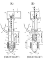
- (A) is a longitudinal side view showing the return path process of the present invention
- (B) is a longitudinal side view showing the forward path process of the present invention
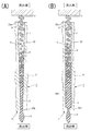
- (A) is a longitudinal side view of the initial position of the melting process of the present invention
- (B) is a longitudinal side view of the intermediate position of the melting process of the present invention
- (C) is a longitudinal side view of the end position of the melting process of the present invention. It is.
- (A) is a main part longitudinal enlarged side view of the initial position of the melting step of the present invention
- (B) and (C) are main part vertical enlarged side views of the intermediate position of the melting process of the present invention
- (D) is the present invention.
- (A) is an enlarged longitudinal side view of a cone-shaped melting hole showing a state in which the pellet moves while melting from the inflow side large opening toward the outflow side small opening
- (B) is the pellet from the inflow side large opening to the outflow side. It is an expansion vertical side view of the fusion hole in which the tip which shows the state moved while melting toward a small opening is narrowed.
- (A) is a vertical side view immediately after the initial position of the injection process of the present invention
- (B) is a vertical side view of an intermediate position of the injection process of the present invention
- (C) is a vertical side view of the end position of the injection process of the present invention.
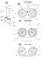
- FIG. 6A is a cross-sectional view taken along the line X1-X1 in FIG. 5A
- FIG. 5E is a perspective view of another embodiment of the on-off valve.
- (A) is the perspective view which partially cut away the melter in which the cone-shaped fusion hole was formed in square shape
- (B) is the state figure of the site
- (A) is an enlarged vertical side view of the melter and on-off valve location of the second embodiment
- (B) is an enlarged vertical side view of the melter and on-off valve location of the third embodiment.
- (A) is an enlarged longitudinal sectional side view of the melting device and on-off valve location of the fourth embodiment
- (B) is a modification of (A), a partial perspective view of the upper part of the melting device
- (C) ( B) is an enlarged cross-sectional view taken along arrow X2-X2
- (D) is an enlarged cross-sectional view taken along arrow Y1-Y1 of (C).
- (A) is a perspective view of a die for producing an H-shaped long product at the outlet member of the injection device of the present invention
- (B) is an enlarged cross-sectional view taken along the line X3-X3 in (A)
- (C) is ( (A) is an enlarged cross-sectional view taken along arrow X4-X4, (D) is an enlarged cross-sectional view taken along arrow X5-X5 in (A), and (E) is an enlarged cross-sectional view taken along arrow X6-X6 in (A).
- FIG. 4C is a longitudinal side view of the present invention
- FIG. 5C is a longitudinal side view of the present invention in a state where the shutter plate of the shutter mechanism in FIG. is there.
- A) is a perspective view schematically showing a state in which two sets of melters and reciprocating rods are arranged in parallel in the injection apparatus of the present invention
- B) is an enlarged cross-sectional view taken along arrow X7-X7 in (A), and (C).
- (A) X8-X8 arrow expanded sectional view of (A)
- (D) is X9-X9 arrow expanded sectional view of (A).
- (A) is a schematic perspective view of a state in which three sets of melters and reciprocating rods are arranged in parallel in the injection apparatus of the present invention
- (B) is an enlarged cross-sectional view taken along arrow X10-X10 in (A)
- (C) is an enlarged cross-sectional view taken along arrow X11-X11
- (D) is an enlarged cross-sectional view taken along arrow X12-X12 in (A).
- the present invention mainly includes a cylinder 1, a melter 2 that melts pellets p, p,..., And drive means 3 that reciprocates the melter 2. And heating means 4.
- An outlet member 5 is provided at the end of the cylinder 1, and the melter 2 and the closing portion 6 that reciprocate are provided therein.
- the closing portion 6 is formed in a plate shape.
- the driving means 3 is provided with a reciprocating rod 34.
- the outlet member 5 is mounted on one end side (lower end in FIG. 1) of the cylinder 1 in the axial direction (or also referred to as the longitudinal direction, and in the vertical direction in FIGS. 1A and 1B).
- the driving means 3 is mounted on the other end side (upper end in FIGS. 1A and 1B) in the axial direction (upper end in the longitudinal direction) via a cylindrical case 13, and the melting means is used by the driving means 3.
- the device 2 is configured to reciprocate (see FIGS. 1 and 2).
- the material of the cylinder 1 needs to be heated quickly, and iron or stainless steel with a high iron content is suitable.
- the cylinder 1 is composed of an elongated cylinder body 11 and a tubular supply pipe 12 connected from a pellet supply port 11a formed near the closing portion 6.
- the supply pipe 12 is configured to communicate with a hopper 8 for storing pellets p, p,.
- the supply pipe 12 is connected by a portion integrated with the cylinder 1 and a pipe formed in an appropriate arc shape.
- the cylinder main body 11 is a cylindrical member, and an inner side of the cylinder main body 11 has a substantially columnar space surrounded by an inner peripheral side surface 11b.
- the thickness of the cylinder body 11 is preferably about 2 mm.
- a large number of pellets p, p,... Can be charged into the hopper 8, and the charged pellets p, p,... Are fed into the cylinder body 11 from the pellet supply port 11a through the supply pipe 12. See FIG. 2A].
- the supply pipe 12 may be provided with a screw conveyance or pneumatic device to forcibly introduce the pellets p, p,.
- the cylinder 1 has a circular cross section, the circle may be slightly deformed to be elliptical. In this case, accurate reciprocation is possible without the melter 2 having the same shape rotating.
- An outlet member 5 such as a nozzle portion 51 or a die 52 is attached to one end side (lower end) of the cylinder body portion 11 in the axial direction (longitudinal direction). As described above, the outlet member 5 includes the nozzle portion 51 and the die 52 (see FIG. 11).
- the nozzle portion 51 is configured to be replaceable so as to change the diameter of the injection portion according to the mold used with the injection device of the present invention.
- the nozzle part 51 includes an injection port 51a and a connection part 51b [see FIG. 1 (A)].
- the injection port 51a is formed to be narrower than the inner diameter of the cylinder body 11, and is a part that is inserted into a gate of a mold (not shown).
- the connection part 51b of the nozzle part 51 and the cylinder body part 11 are detachable with a structure having a screw structure (an outer screw, an inner screw).
- the material of the nozzle part 51 is preferably a material having good thermal conductivity, and specifically, beryllium copper or copper is desirable.
- the die 52 is for manufacturing a long resin product (material).
- the die 52 is attached directly to the cylinder 1 so as to be close to the vicinity of the melter 2 of the cylinder 1 after removing the nozzle portion 51.
- FIG. 52a is formed.
- the specific shape of the forming hole 52a is an “H” shape or the like, but other shapes include an “L” shape, a square, a triangle, a circle, or other polygonal shapes.
- the molding hole 52a is formed as a circular opening on the side where the die 52 is attached to the cylinder 1, and is in a state in which the molten resin q easily flows.
- the forming hole 52a is formed so as to be closer to a desired shape as it goes toward the discharge opening side of the die 52.
- the molding hole 52 a in which the “H” -shaped long resin material is formed, the molding hole 52 a gradually increases from the circular shape toward the outward side from the mounting side to the cylinder 1. It is formed so as to have a shape [see FIGS. 11B to 11E]
- the dice 52 plays a role of manufacturing a long resin shape. That is, long objects having the same cross-sectional shape can be manufactured.
- the melter 2 is formed by forming a large number of melt holes 22, 22,... In a container body portion 21 formed in a substantially cylindrical shape (see FIGS. 1, 5 and 7, etc.).
- the material of the vessel body 21 is preferably a material having a large heat capacity and good heat conduction. Specifically, copper or beryllium copper is used.
- the vessel main body 21 is configured to be reciprocable inside the cylinder main body 11 of the cylinder 1, and is always disposed near the outlet member 5 (see FIG. 1A). .
- the vessel main body 21 of the melter 2 is formed in a cylindrical shape as described above, and a large number of pellets p, p,... Are formed on the side of the vessel main body 21 facing the closing portion 6.
- the surface on the inflow side is referred to as an inflow side surface portion 21a.
- the surface opposite to the inflow side surface portion 21a faces the outlet member 5, and the surface on the side from which the molten resin q flows out is referred to as an outflow side surface portion 21b.
- the outer peripheral side surface of the vessel main body 21 is referred to as a circumferential side surface 21c.
- the vessel body 21 has a cylindrical shape as described above.
- the diameter D2a of the inflow side surface portion 21a and the diameter D2b of the outflow side surface portion 21b are the same as those of the circumferential side surface 21c along the axial direction. It is an exact cylindrical shape having the same diameter (see FIG. 7A). Also, the melting device 2 in FIGS. 1 to 6 has the above exact cylindrical shape.
- the melt hole 22 is formed along the axial direction (longitudinal direction) of the vessel main body 21 (see FIGS. 1 to 6). More specifically, the melt hole 22 is a tunnel-shaped or pipe-shaped conical through-hole [see FIGS. 7B and 7C]. In the melt hole 22, the aforementioned conical through-hole is formed so that the cross-sectional shape at a plurality of arbitrary positions orthogonal to the hole forming direction is changed from a wide shape to a narrow shape. A hole having a gap such as a cone or a pyramid (see FIGS. 7B and 7C and FIGS. 8A and 8B).
- a conical shape is particularly preferable as the conical shape of the melting hole 22, and the diameter is formed so as to gradually decrease from large to small (see FIGS. 7B and 7C).
- the large opening side of the melting hole 22 is referred to as an inflow side large opening 22a into which the pellets p, p,... Flow in (see FIGS. 4A, 4B, 7B, and 7C).
- the small opening side of the melting hole 22 is referred to as an outflow side small opening 22b (see FIGS. 4A, 7B and 7C). That is, the melt hole 22 is a passage that communicates from the inflow side large opening 22a to the outflow side small opening 22b, and the cross section gradually becomes narrower from the inflow side large opening 22a toward the outflow side small opening 22b.
- the inflow side large opening 22a is located in the inflow side part 21a side of the container main body part 21, and faces (or opposes) the said blocking part 6 (refer FIG. 1 (A) and (B)).
- the outflow side small opening 22b is located in the outflow side part 21b, and faces (or opposes) the outlet member 5 (refer FIG. 1 (A) and (B)).
- the inflow side surface portion 21a of the melter 2 is provided with inflow side large openings 22a, 22a,... Of a large number of melting holes 22, 22,. Since the pellets p, p,... Flow into the inflow side large opening 22a facing the plugging portion 6, they are referred to as the inflow side of the melter 2.
- the outflow side surface 21b of the melter 2 is provided with outflow side small openings 22b, 22b,... Of a large number of melting holes 22, 22,.
- the molten resin q in which the pellets p, p,... Are melted out from the outflow side small opening 22b facing the 5 side is referred to as the outflow side of the melter 2.
- the melted state toward the inflow side and the outflow side of the melter 2 is shown in FIGS. 4 (A) and 4 (B).
- the cross-sectional shape of each orthogonal portion is circular along the axial direction (longitudinal direction) [see FIGS. 7B and 7C].
- the inflow side large opening 22a of the melting hole 22 is sized so that one whole pellet p can enter and at least a part (part) of the pellet p can enter.
- the specific size of the inflow side large opening 22a is about 3 to 4 mm in diameter so that the pellets p, p,.
- the outflow side small opening 22b has a diameter of about 1 to 1.5 mm so that the pellets p, p,...
- the melting hole 22 has a substantially tapered cross-sectional shape along the axial direction (longitudinal direction). That is, when the shape is a pyramid along the axial direction (longitudinal direction) and the shape is a pyramid, the shape may be a quadrangular pyramid or a triangular pyramid. There is also a type in which a quadrangular pyramid shape and a conical shape are combined (see FIG. 8). In this type of melting hole 22, the inflow side large opening 22a of the conical melting hole 22 has a polygonal shape of a triangle or more, and the outflow side small opening 22b has a circular shape.
- the inflow side large opening 22a of the conical melting hole 22 is formed in a substantially square shape and the interval between adjacent inflow side large openings 22a and 22a is minimized.
- a portion serving as a boundary between adjacent inflow side large openings 22a, 22a is formed as a blade shape (see FIG. 8A), and the inflow side large openings 22a, 22a,. It is configured in a lattice shape (see FIG. 8A).
- the inflow side large opening 22a having a substantially polygonal shape has a shape such as a triangle or a hexagon in addition to a square such as a square as described above, and the edges of adjacent inflow side large openings 22a and 22a are adjacent to each other. Those that are parallel and linear are preferred.
- the inflow side large openings 22a are formed in a substantially square shape, and a large number of inflow side large openings 22a, 22a,... Constitute a substantially lattice shape (see FIG. 8A). Furthermore, as shown in FIG. 8B, the boundary between the adjacent inflow side large openings 22a, 22a is configured to be a blade shape, so that the periphery of each inflow side large opening 22a has a sharp shape.
- the pellets p, p,... That try to enter the inflow side large opening 22a are caught by the blade-shaped part, they are broken finely by the pressing force by the pellets p, p,.
- the large opening 22a makes it easier to enter.
- FIG. 9A and 9 (B) show another embodiment of the melting hole 22 of the melting device 2, which is formed as a melting hole with a narrowed tip.
- FIG. 9A shows a second embodiment of the melting hole 22 of the melting device 2, and gradually increases from the large diameter to the small diameter so that the inflow side large opening 22 a becomes the outflow side small opening 22 b.
- it is formed as a plurality of cylindrical portions 22c, 22c, and the end portion of the cylindrical portion 22c corresponds to the outflow side small opening 22b, or only the end portion is formed as the outflow side small opening 22b [FIG. (See (A)).
- FIG. 9B is also formed as a melting hole 22 whose tip is narrowed. 3.
- FIG. 10A is also formed as a melting hole 22 whose tip is narrowed.
- the large-diameter cylindrical portion 22d as the inflow side large opening 22a is end so that the inflow side large opening 22a becomes the outflow side small opening 22b.
- the outflow side small opening 22b is formed only at the end portion.
- the inflow side large opening 22a of the melting hole 22 is formed in a circular shape in cross section, and the inlet portion of the inflow side large opening 22a is adjacent to each other with a dish-like chamfer 22a1 formed.
- a portion serving as a boundary between the dish-shaped chamfers 22a1 and 22a1 of the inflow side large opening 22a may be formed as a blade shape 22s. Due to the presence of the blade shape 22s, the pellet p is often crushed and finely separated at the position of the blade shape 22s, and the pellet p becomes easier to enter through the inflow side large opening 22a, thereby promoting the melting of the pellet p. It also has an effect.
- the driving means 3 includes a motor drive unit 31 with a reduction gear, a pinion gear 32, and a rack shaft 33.
- a drive means 3 in which the rod reciprocates by driving a motor drive unit 31 with a speed reducer and a ball screw and a ball screw nut drive.
- a reciprocating rod 34 is connected to the tip of the rack shaft 33 or the rod end.
- the reciprocating rod 34 is passed through substantially the center of the closing portion 6, and its tip is connected to the melter 2.
- the rack shaft 33 is covered with the cylindrical case 13 connected to the rear portion of the cylinder 1 by a screw ring 14, and is fixed to the motor case 38 of the motor drive unit 31.
- the reciprocating rod 34 is made of iron or stainless steel.
- the motor drive unit 31 is configured by a brushless motor, a stepping motor, or the like, and is capable of high-precision drive control.
- the time of the melting process and the injection process of the molten resin q Time can be separated and controlled. As a result, a sufficient time for melting the resin can be ensured, and the injection process of the molten resin q can be performed very quickly and efficiently in a short time.
- the brushless motor is suitable for arbitrarily and accurately controlling different time zones such as when the melting process time is lengthened and the injection process time is shortened.
- the heating means 4 is a structural member that heats the melter 2 from the outer peripheral surface of the cylinder body 11, and is configured in a cylindrical shape so that the thermal conductivity to the melter 2 is good. Specifically, a sufficient amount of heat can be obtained with an IH heater or the like configured in a winding shape.
- the heating means 4 serves to heat the melter 2 that reciprocates in the cylinder body 11 of the cylinder 1.
- the heating means 4 is preferably an electromagnetic induction device, that is, an IH (Induction Heating) coil, and an IH coil is wound around a heat insulating material coil bobbin made of resin or ceramic.
- the bobbin shape is set so that the distance between the IH coil and the outer peripheral side surface of the cylinder body 11 is optimal.
- the input power is preferably variable from 0 to 1 Kw by the control device.
- a thermocouple is attached to the cylinder 1 so that the temperature of the cylinder 1 can be set to a set value.
- a band heater may be used as another type of the heating means 4.
- the heating means 4 is not limited to the one described above, and any other heating device that can be used in the present invention may be used.
- the heating means 4 is fixed to the cylinder body 11, the heat capacity of the melter 2 can maintain a sufficient heat source even if the driving means 3 reciprocates. . This is because it is normally set as the fixed position approaching the position of FIG. 1A, that is, the five outlet members. Even if the melter 2 moves in the return path (melting process) in the pellet storage region W, it immediately moves from the state to the forward path (injection process), and the melter 2 is easily cooled in the heating state. Therefore, a sufficient heating amount can be obtained and a predetermined temperature can be maintained.
- melter 2 is provided with a heat insulating treatment as necessary. This point will be specifically described.
- a reciprocating rod 34 of the driving means 3 is loosely inserted in a central through hole 21d passing through the centers of the inflow side surface portion 21a and the outflow side surface portion 21b of the melter 2. That is, the inner diameter of the center through hole 21d is formed slightly larger than the diameter of the reciprocating rod 34 and is configured not to contact. Further, concave portions 21a1 and 21b1 are formed at the center positions of the inflow side surface portion 21a and the outflow side surface portion 21b of the melter 2, respectively.
- heat insulating materials made of ceramic or polyimide, or stainless steel disk-like support pieces 25, 25 are disposed and fixed to the reciprocating rod 34. Specifically, after one support piece 25 is inserted into the reciprocating rod 34, the tip end side of the reciprocating rod 34 is passed through the central through hole 21 d of the melter 2. The one support piece 25 is disposed in the concave portion 21a1 of the inflow side surface portion 21a of the melter 2.
- the collar member 72 in which the other support piece 25 and the disc 71 are inserted is inserted into the distal end side small diameter portion 34a formed in the reciprocating rod 34.
- the collar member 72 is made of iron or stainless steel.
- a nut 34 c is screwed into the threaded portion 34 b of the tip side narrow diameter portion 34 a of the reciprocating rod 34, and the fuser 2 is fixed to the reciprocating rod 34. That is, the melter 2 is fixed to the reciprocating rod 34 via the support pieces 25, 25 without directly contacting the reciprocating rod 34.
- the reciprocating rod 34 can be in a state where there is almost no heat conduction of the melting device 2. That is, it can be in a heat cutoff state.
- the heat source generated in the melter 2 is configured not to conduct heat to the metal reciprocating rod 34 (mainly stainless steel or the like) inside the cylinder 1.
- the purpose of the heat insulation of the melter 2 is to use the heat quantity of the melter 2 only for melting the pellets p, p,. Therefore, a heat insulating material (support piece 25 or cylindrical collar 35) is interposed between the melting device 2 and the reciprocating rod 34.
- the hole diameter of the outflow side small opening 22b of the melter 2 is much smaller than the inflow side large opening 22a [see FIGS. 6 (A) to (C)], for example, about 1 mm inside and outside
- the surface area of the outflow side surface portion 21b of the melter 2 is much larger than the area of the entire outflow side small opening 22b
- the ratio of the molten resin q that flows backward from the holes of all the outflow side small openings 22b is extremely reduced, and the molten resin q can be injected well from the outlet member 5 by being pressed.
- the injection process of the molten resin q may be performed without providing the opening / closing valve 7 in the melter 2.
- an on-off valve 7 is provided as necessary (see FIG. 1, FIG. 2, FIG. 5, etc.). That is, the on-off valve that opens the inflow side large opening 22a or the outflow side small opening 22b of the melter 2 in the return path process and closes the inflow side large opening 22a or the outflow side small opening 22b of the melter 2 in the outbound path process. 7 is provided.
- the on-off valve 7 is configured to close the front end side of the melter 2 during the forward pass process or to release during the return pass process.
- the on-off valve 7 includes a disc 71 and a collar member 72 with a collar 73.
- the collar member 72 with the flange 73 is located on the front surface of the outflow side surface portion 21b of the melter 2 and is disposed at the tip of the reciprocating rod 34 penetrating through the center of the melter 2 via the collar member 72.
- it is provided so as to be slightly movable back and forth between the flange 73 and the outflow side surface portion 21b.
- the diameter D7 of the disc 71 is smaller than the diameter D2b of the outflow side surface portion 21b [see FIG. 7 (A)]. That means It is. This is to make the molten resin q flow more easily than the outer edge of the on-off valve 7 during the return path process.
- the on-off valve 7 is provided between the outlet member 5 and the melter 2 and is a disk that contacts and separates from the outflow side small opening 22b of the melter 2. 71, and the disk 71 is formed to have a diameter smaller than the diameter of the melter 2.
- the guide pins 71b projecting from the disc 71 are formed so as to be inconsistent with the positions, and can be loosely inserted between the holes 21p formed in the melter 2.
- the circular plate 71 is formed without any number of through holes 71a. That is, only the disk 71 without holes is formed, and the disk 71 is formed with a diameter smaller than the diameter of the melter 2. In the case of this embodiment, all the molten resin q flows from the outer edge of the on-off valve 7 during the return path process.
- the on-off valve 7 is configured to be constantly elastically pressed by an elastic body 75 as a compression spring.
- the disk 71 of the on-off valve 7 is formed to be equivalent to the diameter D2b of the outflow side surface portion 21b of the melter 2, and a plurality of locations (for example, the circumferential edge of the disk 71 (for example, A notch through which the molten resin q flows out may be formed at the four locations).
- the notch is formed in a U shape, a U shape, or the like.
- the disc 71 is configured to be able to contact and separate a little between the collar 73 of the collar member 72 and the surface of the melter 2. Specifically, when the thickness of the circular plate 71 is t, the thickness between the ridge and the surface of the melter is the thickness t + ⁇ , and the contact / separation movement is exhibited within the range of ⁇ [FIG. (See (A)). This is the same movement even when an elastic body 75 as a compression spring is provided.
- pellets p, p,... It is stored on the front side of the inflow side surface portion 21a.
- the pellet storage area W is provided between the rear part of the melter 2 and the closing part 6 when the injection process in the cylinder 1 is finished, and the pellet supply port 11a is located at the rear part position of the pellet storage area W. Is provided.
- FIGS. 2 (B) and 3 (B) When the melting process is turned ON, a large number of pellets p, p,... Contained in the pellet storage area W by the return path process by the driving means 3 are shown in FIGS. 2 (B) and 3 (B). As described above, it is compressed between the inflow side surface portion 21a of the melter 2 and the plugging portion 6 so as to return to the hopper 8 side. Are pushed out and flow into the melt holes 22, 22,... Through the large inflow side large openings 22a, 22a,... [FIG. FIG. 3 (B), FIG. 4 (A)]. As described above, the inflow side large opening 22a has such a size that at least a part (part) of each pellet p enters.
- the inflow side large opening 22a has a size that allows the entire pellet p of average size to enter from the inflow side large opening 22a (see FIG. 4A).
- the pellets p, p,... That have entered the melting holes 22, 22,... are pressed by the pellets p, p,. 4 to maintain the temperature at which the pellet p is melted.
- the pellet p entering from the inflow side large opening 22a melts toward the center of the pellet p as it moves from the inflow side large opening 22a toward the outflow side small opening 22b [see FIG. 4 (A)].
- the pellet p is set so that the periphery of the pellet p is substantially uniformly surrounded by the inner peripheral wall surface of the melting hole 22 in an initial state where the pellet p starts to enter the large opening 22a.
- the pellets p are gradually reduced in size while being melted as they move through the melting hole 22 toward the outflow side small opening 22b [see FIG. 4A]. Even if the pellet p moves while melting toward the outflow side small opening 22b side, the melting hole 22 is gradually narrowed, so that the periphery of the pellet p that has been melted and reduced is uniformly surrounded. is doing. Therefore, the pellet p is melted quickly.
- each pellet p is substantially evenly surrounded by the inner wall surface of the melt hole 22 and always maintains a state of being close to or in contact with the inner wall surface (see FIG. 4A). Then, as the melting of the pellet p proceeds, it further proceeds to a narrow portion of the melting hole 22 to promote the melting of the pellet p. Moreover, since the pellet p is melted and liquefied inside the melting hole 22, the melting of the pellet p fed later is further promoted by the heat of the already liquefied pellet pa [see FIG. 4 (A)]. ].
- the large-diameter cylindrical portion 22d as the inflow-side large opening 22a is formed close to the end, and the outflow-side small opening 22b is formed only on the outflow side.
- the pellet can be pressed on the back side and melted by a heating force to exhibit the same effect as a conical melting hole [see FIG. 4 (B)]. Even such hole drilling can be cheaper.
- the injection apparatus according to the present invention has high melting efficiency and does not require the addition of more materials than necessary, so that the entire apparatus is miniaturized, saving power and resources.
- the fact that the high temperature state of the resin can be shortened to the minimum time by achieving the injection proper temperature and the maximum temperature in the final melting process immediately before injection can also achieve high quality resin molding.
- the shutter mechanism 9 includes a shutter plate 91 and a drive source 92 such as a solenoid that drives the shutter plate 91 up and down.
- the lower end portion of the shutter plate 91 is inserted into a groove portion 12 a formed at the base portion of the supply pipe 12 to close the pellet supply port 11 a, and a flow of a large number of pellets p flowing into the supply pipe 12. Is configured to shut off.
- the pellet p supplied from the hopper 8 is controlled by controlling the time for opening and closing the shutter plate 91 in consideration of the flow speed and flow time of a large number of pellets p. It can be controlled to an appropriate amount.
- the cylinder 1 may be integrally formed up to the position of the case 38 of the motor drive unit 31.
- a plurality of sets of the reciprocating rod 34 of the melting device 2 and the driving means 3 of the present invention may be provided. That is, in the present invention, normally, one melter 2 and the reciprocating rod 34 of one drive means 3 make a pair, and the cylinder 1 has one set of the fuser 2 and A reciprocating rod 34 is mounted [see FIG. 1 (A)]. On the other hand, there is an embodiment in which a plurality of sets of the melter 2 and the reciprocating rod 34 are attached to one cylinder 1 (see FIGS. 13 and 14). These plural sets are arranged in parallel in the cylinder 1 [see FIG. 13 (A), FIG. 14 (A)].
- FIG. 13 An embodiment in which two sets of the fuser 2 and the reciprocating rod 34 are provided in the cylinder 1 will be described (see FIG. 13).
- two gaps 11c and 11c are formed in parallel in the cylinder 1.
- a set of the melter 2 and the reciprocating rod 34 is mounted in parallel in both the gaps 11c and 11c [see FIGS. 13A to 13C].
- the hopper 8 is connected to both the gaps 11c and 11c [see FIG. 13 (B)]. And in the vicinity of the outlet member 5 mounting side of the cylinder 1, the outflow side surfaces 21b, 21b of both the melters 2, 2 are exposed in the cylinder 1, and the molten pellets p, p,. Are mixed, and the molten resin q can be sent out from the outlet member 5 [see FIG. 13D].
- the cylinder 1 is formed in parallel so that the three gaps 11c, 11c,... Have a triangular shape (or rice ball shape). Then, three sets of the melter 2 and the reciprocating rod 34 are mounted in parallel in all the gaps 11c, 11c,... (See FIGS. 14A to 14C).
- the hopper 8 is connected to all the gaps 11c, 11c,... [See FIG. 14 (B)].
- the pellets p, p,... are mixed with each other so that the molten resin q can be sent out from the outlet member 5 (see FIG. 14D).
- the axial direction (longitudinal direction) of the cylinder 1 is installed vertically, but may be installed horizontally or inclined. In particular, when injection molding is performed on a large mold, it may be arranged horizontally.
- SYMBOLS 1 Cylinder, 11a ... Pellet supply port, 2 ... Melting device, 21a ... Inflow side part, 21b ... Outflow side part, 22 ... Melting hole, 22a ... Inflow side large opening, 22b ... Outlet side small opening, 22s ... Blade shape DESCRIPTION OF SYMBOLS 3 ... Drive means, 4 ... Heating means, 5 ... Outlet member, 6 ... Blocking part, 7 ... Open / close valve, 9 ... Shutter mechanism, p ... Pellet, q ... Molten resin.
Abstract
先端射出側には出口部材5が、後部側には塞ぎ部6が、プラスチックペレットpを供給するペレット供給口11aが設けられたシリンダー1と、器本体部21の長手方向に対して流入側大開口22aから流出側小開口22bに連通する多数の溶融孔22が形成され、シリンダー1内径と同径とした溶融器2と、これを加熱する加熱手段4と、溶融器2を往復動させる駆動手段3とからなり、溶融器2の流出側小開口22bが出口部材5と対面させ、溶融器2がシリンダー1内においてプランジャー的な動作をして、駆動手段3の復路がプラスチックペレットを溶融する溶融工程と、往路が溶融樹脂qの射出工程として構成される。
Description
本発明は、加熱状態の溶融器を往復動させることで、投入した多数のプラスチックペレットの樹脂の溶融工程と、溶融樹脂の射出工程とに分離させて、樹脂溶融できる十分な時間を確保すると共に、その溶融樹脂の射出工程を極めて迅速で且つ短時間に効率良くできる成形機における射出装置に関する。
一般に、射出装置は、スクリュータイプ,プランジャタイプのものが存在する。その代表的なものとして、スクリュータイプでは、特許文献1が、プランジャタイプでは、特許文献2にそれぞれ開示されているように、主にシリンダとスクリューとから構成される。シリンダに設けられたホッパから投入されたペレットは、シリンダの内部でスクリューが回転することによって射出ノズル側に移送させられると共に、その移送過程で加熱されて溶融してゆく。そして、溶融した樹脂をノズルの先端に集め、それを射出し、金型に溶融樹脂を送る。
一般のプラスチックペレット(以下、単に『ペレット』という。)は、プラスチック(合成樹脂)製であり、その熱伝導率は約0.07~0.20kcal/m・hr・℃である。これは、金属の熱伝導率の数百分の1から数千分の1であり、このようなことからペレットは、略断熱材と言える。したがって、ペレットを溶融するために、十分な溶融熱を与えても、熱がペレット内部(中心部)まで伝達しにくく、十分に加熱されるのに、かなりの時間がかかってしまう。
したがって、個々のペレットが十分に溶融されて、樹脂成形ができる状態となるまでは短時間ではできないものであった。そのためにシリンダ内で比較的長い時間をかけて、ペレットを溶融させなければならず、作業効率も良好とはいえないものであった。また、前記射出装置において、シリンダ投入した多数のペレットのそれぞれの固体が、加熱されてスクリューが回転することによって、噴射側に移動させるものであり、このとき多数のペレットの一部がシリンダ内壁に押し付けられる状態となる。
つまり、シリンダ内壁に押圧されることになる。そして、押圧される個々のペレットについても、その固体の表面の一部のみがシリンダ内壁に接触するものであり、個々のペレットの溶融は、ペレット固体が部分的に溶融するのみである。シリンダ内でスクリューによってこねられるペレットは、短時間でシリンダ内壁から離れてしまい、十分な加熱が行われず、ペレット固体は全体が溶融されず、大半のペレットは溶融部分と非溶融部分とが混ざり合った状態となる。
ペレットがスクリューによってシリンダ内壁に繰り返して押圧されることで、ペレットの完全な溶融が行われ、溶融したペレットがノズル付近に移送された場合でも、シリンダに貯留している樹脂の量は、1回の射出に必要な量の数十倍以上であり、無駄な量のペレットがシリンダ内に残留することになる。
また、溶融された樹脂がスクリューとシリンダの隙間を通過するときに、樹脂に機械的損傷を与える。特に、ガラス繊維入りのペレットを溶融する場合には問題が多く、スクリューが磨耗してしまう。また、それぞれのペレットがランダムに一部のみの溶融となるため、シリンダ内にいつまでも同じペレットが残留してしまうことは避けられない。そのために、シリンダ内のペレットにおける材料替えを行う際は、特に、作業が大変である。
このようなスクリュータイプに対してプランジャタイプのものが存在する。この種のものでは、構造が簡単で、且つ小型化にし易いものである。また、スクリューが磨耗するという欠点もプランジャタイプには存在しない。特許文献2は、最も基本的な構造を有するプランジャタイプのものであり、主に多数の貫通孔を有する裁頭円錐状の加熱筒と、射出プランジャと、供給筒等から構成されたものである。そして、射出プランジャにより、合成樹脂原料が加熱筒に送り出され、射出が行われる。しかし、特許文献2においても、種々の問題点を有している。
特許文献2では、射出プランジャと、裁頭円錐状の加熱筒は、その対面する両者の直径が異なるもので、射出プランジャの直径が加熱筒の対面箇所の直径よりも一回り小さく形成されている。また、射出プランジャの先端と加熱筒と射出プランジャの先端部分と供給筒との間には、射出プランジャの先端の面積よりも広い容積の空隙室が存在する。
したがって、溶融した合成樹脂原料は、射出プランジャによって、一旦、前記空隙室に押出されるが、射出プランジャがさらに加熱筒側に移動しても、合成樹脂原料が加熱筒の貫通孔に効率良く流入することができないものであり、加熱筒に流入しないで空隙室に残留してしまうおそれが十分にある。そして、前記空隙部に残留した合成樹脂原料は、加熱筒の貫通孔に新たに送り出そうとする合成樹脂原料の障害となるおそれがある。また、新たに送り出そうとする合成樹脂原料と、長期間残留して劣化した樹脂とが混合されてしまうおそれも十分にある。
そのような裁頭円錐状の加熱筒及び射出プランジャの不都合な点を改良し、極めて良好にペレットの樹脂溶融工程と、溶融樹脂の射出工程が効率良くできる成形機における射出装置を、本願出願人は、特許文献3にて開発した。この特許文献3では、ペレットの集合体を、プランジャにて押圧するのみで、ペレットが樹脂溶融できると同時に、溶融樹脂の射出ができるという画期的な発明を提供できたものである。
この発明では、ペレットを溶融させる溶融工程としては、加熱された溶融器の多数の錐状孔を所定の圧力にて通過することで、ペレットなる固体から出口から出たときに溶融樹脂となる。つまり、ペレットの材質、溶融樹脂の粘性、溶融温度、圧力、溶融速度、押出速度、流量等が関連して、溶融速度と射出速度とが同一となっている。すると、溶融速度で考慮するとかなり早く溶融できるものであるが、今度は、射出速度だけを考察すると、溶融速度と同じ時間となり、射出時間が遅いように感じられるものであった。
そこで、発明が解決しようとする課題(発明の目的)は、加熱された溶融器の多数の錐状孔又は錐状に近似する孔を所定の圧力にて通過させて樹脂を溶融する溶融工程と、その後の溶融樹脂の射出工程とを分離した上で、射出工程の迅速化を図ることを実現することである。つまり、溶融工程と射出工程を繰り返し行うことで、該射出工程を溶融工程の時間に関係なく設定させることで、射出工程の飛躍的な迅速化を図ることである。
そこで、発明者は、上記課題を解決すべく、鋭意,研究を重ねた結果、本発明の第1の実施態様を、長手方向の先端射出側には出口部材が、その後部側には塞ぎ部が、該塞ぎ部と前記出口部材との中間位置にプラスチックペレットを供給するペレット供給口がそれぞれ設けられたシリンダと、器本体部の長手方向に対して流入側大開口から流出側小開口に連通する多数の溶融孔が形成され且つ前記シリンダ内径と同径とした溶融器と、前記溶融器を加熱する加熱手段と、前記溶融器を往復動させる駆動手段と、からなり、前記溶融器の前記流出側小開口が前記出口部材と対面してなると共に、前記溶融器が前記シリンダ内においてプランジャ的な動作をなして、前記駆動手段の復路が前記プラスチックペレットを溶融する溶融工程と、その往路が溶融樹脂の射出工程としてそれぞれ構成されてなり、前記シリンダ内で、前記出口部材と前記溶融器との間に開閉弁が介在され、該開閉弁は、前記溶融器の復路工程では該溶融器の流出側小開口側を解放するように構成され、且つ前記溶融器の往路工程では該溶融器の流出側小開口側を閉じるように構成されてなることを特徴とする成形機における射出装置としたことにより、前記課題を解決した。
本発明の第2の実施態様を、第1実施態様において、前記開閉弁は、円板型であって、該円板直径は前記溶融器直径よりも小径に形成されると共に、前記溶融器側に常時弾力圧するように構成されて、前記溶融器が往路での溶融樹脂の射出工程の場合には、前記開閉弁にて前記溶融器流出側小開口孔を塞ぐことを特徴とする成形機における射出装置としたことにより、前記課題を解決した。
本発明の第3の実施態様を、第1実施態様において、前記開閉弁は、円板型であって、多数穿孔された孔の位置は、前記多数貫孔が穿孔された流出側小開口孔とは位置ずれして形成されると共に、前記溶融器側に常時弾力圧するように構成されて、前記溶融器が往路での溶融樹脂の射出工程の場合には、前記開閉弁にて前記溶融器流出側小開口孔を塞ぐことを特徴とする成形機における射出装置としたことにより、前記課題を解決した。
本発明の第4の実施態様を、第1実施態様又は第2実施態様において、前記溶融器の溶融孔は、前記流入側大開口から前記流出側小開口になるように錐状に形成されてなることを特徴とする成形機における射出装置としたことにより、前記課題を解決した。本発明の第5の実施態様を、第1実施態様又は第2実施態様において、前記溶融器の溶融孔は、前記流入側大開口としての大径円筒部が端部寄りまで形成され、且つ流出側にのみに前記流出側小開口が形成されてなることを特徴とする成形機における射出装置としたことにより、前記課題を解決した。
本発明の第6の実施態様を、第1実施態様又は第2実施態様において、隣接する前記溶融孔の流入側大開口は断面円形に形成され、且つ該流入側大開口の入口箇所は皿状面取りがそれぞれ形成されると共に、隣接する流入側大開口の皿状面取り同士の境目となる部位が刃状として形成されてなることを特徴とする成形機における射出装置としたことにより、前記課題を解決した。
本発明の第7の実施態様を、第1実施態様又は第2実施態様において、前記ペレット供給口に、該ペレット供給口を開口又は閉鎖するためのシャッタ機構が設けられてなることを特徴とする成形機における射出装置としたことにより、前記課題を解決した。本発明の第8の実施態様を、第1実施態様又は第2実施態様において、前記溶融器及び駆動手段の往復動杆は、それぞれ組をなして複数具備されると共に、複数の組は並列に配置されてなることを特徴とする成形機における射出装置としたことにより、前記課題を解決した。
本発明の第9の実施態様を、第8実施態様において、前記溶融器及び往復動杆からなる組は、2組として並列配置されてなることを特徴とする成形機における射出装置としたことにより、前記課題を解決した。本発明の第10の実施態様を、第8の実施態様において、前記溶融器及び往復動杆からなる組は、3組以上として並列配置されてなることを特徴とする成形機における射出装置としたことにより、前記課題を解決したものである。
本発明では、加熱状態の溶融器を往復動させることで、投入した多数のペレットを溶融する溶融工程と、溶融樹脂の射出工程とに分離させて、ペレットを溶融できる十分な時間を確保すると共に、その溶融樹脂の射出工程を極めて迅速で且つ短時間に効率良くできる最大の効果を奏する。特に、本発明では、溶融器本体がプランジャ的な動作をなすことで、出願人が従来必要としていた別部材のプランジャが無くとも、その往復動で溶融工程と射出工程とを実現できることで大きな効果が得られる。
特に、実験例では、多数のペレットがシリンダ内に詰まっている状態で、溶融器を復路工程で可動させたときに、シリンダ内に充満された多数のペレット群が逆流しないで、ペレット相互が押圧され、この動作にて、流入側大開口から流出側小開口に連通する多数の溶融孔を通過することでペレットが溶融して、樹脂溶融ができるものである。これにより、溶融樹脂が良好にできるものである。
具体的には、前記溶融器の前記流出側小開口側面が、プランジャの押圧面としての役割をなし、前記溶融器の前記流出側小開口側面の前記シリンダ内に、溜まった溶融樹脂が、一度の押圧で、迅速且つ早期に前記ノズル部を介して外側に射出することができる利点がある。つまり、多数のプラスチックペレットの樹脂溶融工程と、溶融樹脂の射出工程とに分離させることで、良好な樹脂溶融ができる十分な時間を確保できるし、且つ、溶融樹脂は、溶液状のため、最大速度であっても対応でき、短時間に効率良く射出できるものである。
押圧された多数のペレットは、無駄が一切なく、直接、溶融器の溶融孔の多数の流入側大開口に送り込むことができる。したがって、塞ぎ部と前記溶融器の流入側面部との間の多数のペレットが順次送り込むことができる。塞ぎ部と前記溶融器の流入側面部との間に押圧されて、前記溶融孔の流入側大開口から入り込んだペレットは、溶融孔の内周壁面に囲まれる状態となり、溶融孔が錐状又は錐状に近似する孔の通路であるから流出側小開口側への移動に伴い次第に押圧力が大きくなると共に加熱にて溶融されて小さくなる。
溶融器自体は、加熱手段によりペレットの溶融温度に加熱されており、ペレットが溶融してゆく。このとき、ペレットの全周囲は溶融孔の内周壁面により囲まれた状態であり、ペレットは外周から中心部に略均等にバランス良く溶融してゆくことができる。しかも、ペレットが、溶融孔を流入側大開口から流出側小開口に向かって移動する過程で、器本体部は、熱容量が大きいので、加熱手段にて一旦、高温に加熱されると、溶融器は、溶融したペレットの温度に影響されることなく、ペレットを加熱しつつ、十分な溶融温度に維持してゆくことができる。
そして、ペレットが外周から中心に向かって略均等に溶融しつつ、次々に流入側大開口から入り込む多数のペレットに押圧されて、溶融孔の流出側小開口に移動することができ、その間にもペレットは溶融が進行し、溶融孔の軸方向(長手方向)の略中間を通過した当たりでは溶融された部分が殆どであり、溶融器の溶融熱と共に周囲のペレットも溶融が加速度的に進行する。流出側小開口付近では、ペレットは最高温度で完全に溶融しており、溶融樹脂として、前記シリンダ内に溜めることができる。
このように、本発明において、溶融器は、器本体部に多数の先が窄まる溶融孔を有するものであり、加熱手段により溶融温度に加熱された多数の先が窄まる溶融孔に、シリンダのペレット貯留領域内において押出されたペレット群が大開口側である流入側大開口より入り込むことで、ペレットがバランス良く溶融し、且つ溶融器の熱容量が大きいので高温状態を維持することができ、溶融が促進されて溶融速度も速くなり、出口部材側に溶融樹脂が溜められる。
特に溶融器は、加熱手段によって、流出側小開口部分で樹脂の温度が最高に達することである。射出直前に必要な最適温度で且つ最高温度にすることができ、高温状態を最短時間にすることで樹脂を劣化させないので、高品質の成形が可能となる。つまり、溶融器は、樹脂が溶融する一番最後の過程で、射出直前に樹脂を最適温度に上げることができる構造である。
さらに、溶融器は、器本体部に、多数の錐状の通路又は錐状に近似する通路が形成された溶融孔を有しており、これら多数の溶融孔は、流入側面部から流出側面部に向って集束することなく、略平行状態に配置されることができる。これによって、多数の流出側小開口は、密集することなく、それぞれ均等に配置されることができる。したがって、溶融器自体の熱容量は、十分に大きいものにできると共に、流出側面部寄りにおける溶融孔間の肉厚部(中実部)の体積を十分に大きく確保することができ、溶融孔間の熱容量も大きくすることができる。
そのため、ペレットが、溶融孔を流入側大開口から流出側小開口に向かって移動する過程で、溶融器が加熱手段にて一旦、高温に加熱されると、大きな熱容量によって高温が維持され、溶融したペレットは温度が低下することなく、十分な溶融温度を維持して、良質なペレット群による溶融樹脂ができる。
さらに、本発明においては、開閉弁の存在により、溶融工程においても、溶融樹脂が良好に生産できるし、特に、射出工程時において、前記溶融器内での溶融樹脂の逆戻りを無くしてスムーズな射出ができる利点がある。
第2実施態様及び第3実施態様では、本発明と同等の効果を奏する。第4実施態様では、前記流入側大開口から前記流出側小開口になるように錐状に形成されていることで、良好なる溶融ができる利点がある。
第5実施態様では、前記溶融器の溶融孔は、前記流入側大開口としての大径円筒部が端部寄りまで形成され、且つ流出側にのみに前記流出側小開口が形成されていることから、先端寄りまでが円筒部の径(直径)で形成加工でき、円錐形の加工に比較して格段と安価に溶融器の製造ができる。このように形成した溶融孔であっても、ペレットが奥側では押圧されつつ加熱力による溶融にて、円錐状の溶融孔と同様な効果を奏する。
第6実施態様では、隣接する前記溶融孔の流入側大開口は断面円形に形成され、且つ該流入側大開口の入口箇所は皿状面取りがそれぞれ形成されると共に、隣接する流入側大開口の皿状面取り同士の境目となる部位が刃状として形成されていることにより、隣接する流入側大開口の皿状面取り同士の境目の刃状箇所で破砕され、細かく分離されるので、ペレットは流入側大開口により一層入り易くなり、ペレットの溶融を促進させることができる。
第7実施態様では、ホッパから供給されたペレットを適宜の量に制御でき、このようにペレットの所望の溶融量を溶融及び射出させることで、これらを整然と作業できる利点がある。
第8実施態様では、前記溶融機及び前記往復動杆は、それぞれ組をなして複数具備されているため、大量のペレットを必要とする大型の金型に対して好適であり、また、本発明における射出装置から出口部材にダイスを使用して、直接、長尺となるワーク(製品)を形成するとき等においても極めて好適である。
第9実施態様では、第8実施態様において、前記溶融機及び前記往復動杆からなる組は、2組として並列配置されていることにより、比較的小型ながら、大型の金型に対応しうるものにできる。
また、第10実施態様では、第8実施態様において、前記溶融機及び前記往復動杆からなる組は、3組以上として並列配置されたことにより、より一層、大型の金型に対応しうるものにできる。
以下、本発明を図面に基づいて説明する。本発明は、図1(A)及び(B)に示すように、主にシリンダ1と、ペレットp,p,…を溶融する溶融器2と、該溶融器2を往復動させる駆動手段3と、加熱手段4とから構成されている。前記シリンダ1の端には出口部材5が、この内部には、往復動する前記溶融器2と塞ぎ部6がそれぞれ設けられている。該塞ぎ部6は、実施形態では、板状に形成されているが、前記シリンダ1の内面を塞ぐことができれば、球面状をなしても、実施形態に制限されない。前記駆動手段3には往復動杆34が設けられている。
また、前記シリンダ1の軸方向(又は長手方向ともいい、図1(A) 及び(B)において、上下方向)の一端側(図1において下端)に前記出口部材5が装着され、軸方向(長手方向の上端)他端側[図1(A)において上端]には前記塞ぎ部6が内臓されている。さらに、軸方向(長手方向の上端)他端側[図1(A)及び(B)において上端]には筒状ケース13を介して前記駆動手段3が装着され、該駆動手段3によって前記溶融器2が往復動するように構成されている(図1及び図2参照)。
前記シリンダ1の材質は、加熱が迅速に行われることが必要であり、鉄又は鉄の含有量の多いステンレスなどが好適である。該シリンダ1は、細長く形成されたシリンダ本体部11と、前記塞ぎ部6寄りに形成されたペレット供給口11aから接続された管状の供給管12とで構成されている。該供給管12には、ペレットp,p,…を溜めておくホッパ8に連通するように構成されている。前記供給管12は、前記シリンダ1に一体化された部分と適宜弧状に形成されたパイプとで結合されている。前記シリンダ本体部11は円筒状の部材であり、その内方側は内周側面部11bによって包囲された略円柱状の空隙を有する。
前記シリンダ本体部11の肉厚寸法は、約2mm程度のものが好ましい。前記ホッパ8には、多数のペレットp,p,…が投入可能であり、投入されたペレットp,p,…は、供給管12を通して前記ペレット供給口11aからシリンダ本体部11内に送り込まれる〔図2(A)参照〕。また、特に図示しないが、供給管12にスクリュー搬送又は空気圧装置を具備して、ペレットp,p,…を強制的に投入することもある。前記シリンダ1の断面は、円形をなしているが、僅かに円が変形して楕円状となる場合もある。この場合には、これと同一形状の溶融器2が回転等することなく、正確な往復動が可能となる。
前記シリンダ本体部11の軸方向(長手方向)の一端側(下端)には、ノズル部51又はダイス52等の出口部材5が装着されている。該出口部材5は、前述したようにノズル部51及びダイス52(図11参照)が存在する。前記ノズル部51は、本発明の射出装置と共に使用する金型に合わせて射出部分の口径を変更させるように交換可能に構成されている。前記ノズル部51は、射出口51aと接続部51bとから構成される〔図1(A)参照〕。
前記射出口51aは、シリンダ本体部11の内径よりも狭く形成されたもので、図示されない金型のゲートに挿入する部位である。前記ノズル部51の接続部51bと、シリンダ本体部11とは、図示しないが、螺子構造(外螺子,内螺子)による構成で着脱自在となっている。前記ノズル部51の材質は、熱伝導の良いものが好適で、具体的には、ベリリウム銅又は銅が望ましい。
前記ダイス52は、樹脂製長尺物(材)を製造するものである。該ダイス52は、前記ノズル部51を外してシリンダ1の溶融器2付近に近接するようにシリンダ1に直接、装着するものであり、図11に示すように、例えば、適宜の形状の成形孔52aが形成されたものである。該成形孔52aの具体的な形状としては、「H」字形状等であるが、その他の形状として、「L」字形状,四角,三角,円又はその他の多角形状等が存在する。
前記成形孔52aは、ダイス52のシリンダ1への装着側では、円形状の開口として形成され、溶融樹脂qが流入し易い状態となっている。そして、成形孔52aは、ダイス52の吐出開口側に向かうに従い所望の形状に近くなるように形成されている。具体的に、「H」字形状の樹脂製長尺材が形成される成形孔52aでは、該成形孔52aはシリンダ1への装着側から外方側に向かうに従い、円形から次第に「H」字形状となるように形成される〔図11(B)乃至(E)参照〕このように、ダイス52は、長尺な樹脂製の形材を製造する役目をなすものである。つまり、断面形状が同一な長尺物を製造することができる。
前記溶融器2は、略円筒形状形成された器本体部21に多数の溶融孔22,22,…が形成されたものである(図1,図5及び図7等参照)。前記器本体部21の材質は、熱容量が大きく、且つ熱伝導の良いものが好適である。具体的には、銅又はベリリウム銅が使用される。前記器本体部21は、前記シリンダ1のシリンダ本体部11内部で、往復動可能に構成され、常時には、前記出口部材5寄りに位置するように配置されている〔図1(A)参照〕。
前記溶融器2の器本体部21は、前述したように円筒形状に形成されたものであり、該器本体部21において前記塞ぎ部6と対面する側で且つ多数のペレットp,p,…が流入してくる側の面を流入側面部21aと称する。該流入側面部21aと反対側の面で前記出口部材5と対面し、溶融樹脂qが流出する側の面を流出側面部21bと称する。
また、前記器本体部21の外周側面を円周側面21cと称する。前記器本体部21は、前述したように円筒形状であり、流入側面部21aの直径D2aと、流出側面部21bの直径D2bとは、円周側面21cは、軸方向に沿っていずれの位置も同一直径となる正確な円筒形状である〔図7(A)参照〕。また、図1~図6における溶融器2についても、上記の正確な円筒形状としたものである。
すなわち、
 である〔図7(A)参照〕。
次に、溶融孔22は、器本体部21の軸方向(長手方向)に沿って形成されたものである(図1~図6参照)。さらに詳しくは、溶融孔22は、トンネル状或いは管路状とした錐状の貫通孔である〔図7(B),(C)参照〕。溶融孔22において、前述した錐状の貫通孔とは、孔形成方向に直交する複数の任意の位置の断面形状が広い形状から狭い形状となるように形成されたものであり、具体的には円錐或いは角錐等の空隙を有する孔である〔図7(B),(C)及び図8(A),(B)参照〕。
本発明では、特に、溶融孔22の錐状として円錐形状が好ましく、直径が大から小に向かって次第に小さくなるように形成されている〔図7(B),(C)参照〕。前述したように、溶融孔22は、錐体状の空隙を有する孔であるために、該溶融孔22の両端の開口の大きさは異なる。そこで、前記溶融孔22の大開口側は、ペレットp,p,…が流入する流入側大開口22aと称する〔図4(A),(B),図7(B)及び(C)参照〕。
また、前記溶融孔22の小開口側を流出側小開口22bと称する〔図4(A),図7(B)及び(C)参照〕。つまり、溶融孔22は、流入側大開口22aから流出側小開口22bに連通する通路であり、流入側大開口22aから流出側小開口22bに向かって次第に断面が狭くなる。そして、流入側大開口22aは、器本体部21の流入側面部21a側に位置し、前記塞ぎ部6に対面(又は対向)する〔図1(A)及び(B)参照〕。また、流出側小開口22bは流出側面部21bに位置し、出口部材5に対面(又は対向)する〔図1(A)及び(B)参照〕。
以上述べたように、溶融器2の流入側面部21aには、多数の溶融孔22,22,…の流入側大開口22a,22a,…が配置されたものであり、前記流入側面部21aは、前記塞ぎ部6に対面して流入側大開口22aにペレットp,p,…が流れ込むので、溶融器2の流入側と称する。
また、前記溶融器2の流出側面部21bには、多数の溶融孔22,22,…の流出側小開口22b,22b,…が配置されたものであり、前記流出側面部21bは、出口部材5側に対面して流出側小開口22bからペレットp,p,…が溶融した溶融樹脂qを流出させるので、溶融器2の流出側と称する。そして溶融器2の流入側及び流出側に向かっての溶融状態については図4(A)及び(B)に示されている。
溶融孔22を円錐形状の孔とした場合では、軸方向(長手方向)に沿って、それぞれの直交する箇所の断面形状は円形状である〔図7(B)及び(C)参照〕。そして、溶融孔22の流入側大開口22aは、1個のペレットp全体が入り込む大きさであり、少なくとも該ペレットpの一部(一部分)が入り込むような大きさとしている。流入側大開口22aの具体的な大きさは、ペレットp,p,…が容易に入り易いような直径で、約3~4mm程度である。
流出側小開口22bは、ペレットp,p,…が溶融して液化した溶融樹脂qとなるような直径は約1~1.5mm程度である。溶融孔22は、その軸方向(長手方向)に沿った断面形状が略テーパー形状である。つまり、軸方向(長手方向)に沿って錐状であり、角錐状とした場合には、四角錐形状としたり、或いは三角錐形状とすることもある。また、四角錐形状と円錐形状を組合わせたタイプも存在する(図8参照)。このタイプの溶融孔22では、円錐形状の溶融孔22の流入側大開口22aを三角形以上の多角形状とし、流出側小開口22bを円形状としたものである。
さらに具体的には、錐状の溶融孔22の流入側大開口22aが略正方形に形成され、隣接する流入側大開口22a,22a同士の間隔が最小限となるように形成された実施形態も存在する〔図8(A)及び(B)参照〕。この実施形態では、隣接する流入側大開口22a,22aの境目となる部位が刃状として形成されることになり〔図8(A)参照〕、集合する流入側大開口22a,22a,…が格子形状に構成される〔図8(A)参照〕。また、略多角形状とした流入側大開口22aは、前述したように正方形等の四角形の他に、三角形,六角形等の形状も存在し、隣接する流入側大開口22a,22a同士の縁が平行且つ直線状となるものが好ましい。
このように、流入側大開口22aを略正方形状とし、多数の流入側大開口22a,22a,…によって略格子状を構成されている〔図8(A)参照〕。さらに、隣接する流入側大開口22a,22aの境目が、図8(B)に示すように、刃状となるように構成されることで、各流入側大開口22aの周縁は鋭利な形状となり、流入側大開口22aに入り込もうとするペレットp,p,…が刃状部位に引っ掛かると、前記塞ぎ部6に押圧されるペレットp,p,…群による押圧力によって、細かく破断され、流入側大開口22aにより一層入り易い状態となる。
図9(A)及び(B)は、前記溶融器2の溶融孔22の別の実施形態であって、先が窄まる溶融孔として形成されている。図9(A)は、前記溶融器2の溶融孔22の第2実施形態であって、前記流入側大開口22aから前記流出側小開口22bになるように、大径から小径に徐々になりつつ複数の円筒部22c,22cとして形成され、端部が円筒部22cが前記流出側小開口22bに該当したり、或いは、端部のみが前記流出側小開口22bとして形成されている〔図9(A)参照〕。
図9(B)も、先が窄まる溶融孔22として形成されている。前記溶融器2の溶融孔22の第3実施形態であって、前記流入側大開口22aから前記流出側小開口22bになるように、大径から中間径程度の直径となるような円錐形孔が形成され、端部のみが前記流出側小開口22bとして形成されている。
図10(A)も、先が窄まる溶融孔22として形成されている。前記溶融器2の溶融孔22の第3実施形態であって、前記流入側大開口22aから前記流出側小開口22bになるように、前記流入側大開口22aとしての大径円筒部22dが端部寄りまで形成され、且つ端部のみに前記流出側小開口22bが形成されている。
図10(B)においては、前記溶融孔22の流入側大開口22aは、断面円形に形成され、且つ該流入側大開口22aの入口箇所は皿状面取り22a1がそれぞれ形成されると共に、隣接する流入側大開口22aの皿状面取り22a1,22a1同士の境目となる部位が刃状22sとして形成されることもある。該刃状22sの存在により、該刃状22s箇所で、ペレットpが破砕され、細かく分離されることが多くなり、ペレットpが流入側大開口22aにより一層入り易くなり、ペレットpの溶融を促進作用も呈する。
前記駆動手段3は、減速機付きのモータ駆動部31,ピニオンギア32及びラック軸33とから構成されている。或いは、図示しないが、減速機付きのモータ駆動部31と、ボールねじとボールねじナット駆動との駆動によりロッドが往復動する駆動手段3も存在する。前記ラック軸33の先端又は前記ロッド端には、往復動杆34が連結されている。
該往復動杆34が、前記塞ぎ部6の略中央に貫通され、その先端が前記溶融器2に接続されている。前記ラック軸33は、前記シリンダ1の後部に、ねじ環14によって接続された前記筒状ケース13にて覆われており、前記モータ駆動部31のモータケース38に固定されている。前記往復動杆34は、鉄又はステンレス製等で構成されている。
前記モータ駆動部31は、ブラシレスモータ又はステッピングモータ等で構成され、高精度の駆動制御が可能であり、且つペレットの材質等を考慮して、溶融工程の時間と、溶融樹脂qの射出工程の時間とを分離させて制御できる。その結果、樹脂を溶融できる十分な時間を確保すると共に、その溶融樹脂qの射出工程を極めて迅速で且つ短時間に効率良くできる。
例えば、溶融工程時間を約30乃至約60秒とし、溶融樹脂の射出工程時間を約1秒程度とすることによって、射出工程時間を極めて迅速で且つ短時間に効率良くできる最大の利点がある。特に、前記ブラシレスモータは、溶融工程時間を長くし、射出工程間を短くするとき等のように異なる時間帯を、任意に且つ正確に制御するのに好適である。
加熱手段4は、前記シリンダ本体部11の外周面から前記溶融器2を加熱する構成部材であり、該溶融器2への熱伝導性が良好となるように筒状に構成されている。具体的には、IHヒータ等が巻き線状に構成されたもので十分な熱量が得られる。
前記加熱手段4は、シリンダ1のシリンダ本体部11内において往復動する溶融器2を加熱する役目をなす。加熱手段4は、具体的には、電磁誘導装置つまりIH(インダクションヒーティング)コイルが好適であり、樹脂又はセラミック製の断熱材コイルボビンにIHコイルを巻いたものである。
IHコイルとシリンダ本体部11の外周側面との間隔が最適になるようにボビンの形状が設定されている。入力電力は、制御装置により0乃至1Kwまで可変可能としたものが好適である。前記シリンダ1には、熱電対が取り付けられており、シリンダ1の温度を設定値にすることができるようになっている。また加熱手段4の別のタイプとして、バンドヒーターが使用されることもある。さらに、加熱手段4は、前述したものに限定されるものではなく、その他の本発明に使用可能な加熱装置であれば何れのものが使用されても構わない。
前記加熱手段4は、前記シリンダ本体部11に固定状態にセットされているが、前記溶融器2の熱容量的には、駆動手段3にて往復動しても、十分に熱源を保つようにできる。これは、常時は、図1(A)位置、即ち、出口部材5箇所に近づいた定位置としてセットされていることによる。ペレット貯留領域W内において、前記溶融器2が復路に動いて(溶融工程)も、その状態から直ぐに、往路に動く(射出工程)ことになり、溶融器2は、加熱状態が簡単には冷えず、十分な加熱量を得ることができ、所定の温度を保持することができる。
また、前記溶融器2については、断熱処理が必要に応じて設けられている。この点について具体的に説明する。前記溶融器2の流入側面部21a及び流出側面部21bの中心を通る中心貫通孔21d内に、前記駆動手段3の往復動杆34が遊挿されている。つまり、前記中心貫通孔21dの内径が、前記往復動杆34の直径よりも僅かに大きく形成され、接触しないように構成されている。さらに、前記溶融器2の流入側面部21a及び流出側面部21bの中心位置に、それぞれ凹部21a1及び21b1が形成されている。
該凹部21a1及び21b1には、セラミック製又はポリイミド製等の断熱材或いはステンレス製で円板状の支持片25,25が配置されつつ、前記往復動杆34に固定されている。具体的には、一方の支持片25が前記往復動杆34に挿入された後に、該往復動杆34の先端側が前記溶融器2の中心貫通孔21dに貫通される。そして、前記一方の支持片25が前記溶融器2の流入側面部21aの凹部21a1に配置される。
この状態にて、他方の支持片25及び円板71が挿入されたカラー部材72が前記往復動杆34に形成された先端側細径部34aに挿入される。前記カラー部材72は、鉄又はステンレス製等で構成されている。さらに、前記往復動杆34の先端側細径部34aのねじ部34bにナット34cが螺合されて該往復動杆34に前記溶融器2が固定される。つまり、前記溶融器2は、直接には前記往復動杆34に接触しないで、前記支持片25,25を介して前記往復動杆34に固定されるものである。このため、該往復動杆34には、前記溶融器2の熱伝導は、殆ど無い状態にできる。つまり、熱遮断状態にできる。
これらの構造によって、溶融器2に発生する熱源は、前記シリンダ1の内部の金属製(主に、ステンレス製等)の往復動杆34に熱伝導しないように構成されている。以上のように、前記溶融器2の断熱の目的としては、溶融の際に溶融器2の熱量がペレットp,p,…の溶融にのみに使われるようにすることである。そのために、前記溶融器2と前記往復動杆34との間に断熱材(支持片25又は筒状カラー35)が介在されている。
特に、前記溶融器2の流出側小開口22bの孔径が流入側大開口22aに対して格段と小さい場合[図6(A)~(C)参照]、例えば、約1mm内外の場合には、駆動手段3による往路工程によって、溶融樹脂qを出口部材5を介して押圧しても、前記溶融器2の流出側面部21bの表面積が全流出側小開口22bの面積よりも格段と大きく、該全流出側小開口22bの孔部から逆流する溶融樹脂qの割合は極端に少なくなって、押圧されて出口部材5から溶融樹脂qを良好に射出できる。このように、前記溶融器2に開閉弁7を設けなくとも、溶融樹脂qの射出工程を行うこともある。
前記溶融器2の内部構造としては、開閉弁7が必要に応じて設けられている(図1,図2及び図5等参照)。つまり、前記溶融器2の流入側大開口22a又は流出側小開口22bを復路工程では開き、前記溶融器2の流入側大開口22a又は流出側小開口22bを往路工程では閉じるようにした開閉弁7が設けられている。
具体的には、該開閉弁7は、往路工程の時に、前記溶融器2の先端側を閉鎖したり、或いは、復路工程の時に、解放するように構成されている。具体的には、前記開閉弁7は、円板71と、鍔73付きカラー部材72とから構成されている。該鍔73付きカラー部材72が、前記溶融器2の流出側面部21bの前面に位置し、前記溶融器2の中心を貫通された前記往復動杆34の先端部に、前記カラー部材72を介して、前記鍔73と前記流出側面部21bとの間で、僅かに前後動可能に設けられている。
前記円板71の直径D7は、前記流出側面部21bの直径D2bよりも小径に形成されている〔図7(A)参照〕。
つまり、
 である。これは、復路工程の時に、溶融樹脂qが前記開閉弁7の外縁より流れやすくするためである。
つまり、
前述の構成を簡単に説明すると、前記開閉弁7は、前記出口部材5と前記溶融器2との間に設けられると共に、前記溶融器2の流出側小開口22bに対して接離する円板71としてなり、該円板71は前記溶融器2の直径よりも小径に形成されて構成されている。
前記開閉弁7における円板71には、図7(B)及び(D)に示すように、多数の貫孔71aが形成され、該貫孔71aは前記溶融器2の流出側小開口22bの位置とは不一致するように形成されてなると共に、前記円板71に突設された案内ピン71bが前記溶融器2に形成された穴部21p間に遊挿可能に構成されている。
前記開閉弁7の別の実施形態では、図7(E)に示すように、円板71において、多数の貫孔71aを全く無くして形成されている。すなわち、孔無しの円板71のみであって、該円板71は前記溶融器2の直径よりも小径に形成されている。この実施形態の場合には、復路工程の時に、溶融樹脂q全てが前記開閉弁7の外縁より流れる。
前記開閉弁7付き前記溶融器2が射出工程時において、金型内に、溶融樹脂qを注入する際には、特に、出口部材5内の溶融樹脂qも高圧になることもあって、逆流することもあるため、前記開閉弁7が、圧縮バネとしての弾性体75にて常時弾力圧するように構成されている。
前記開閉弁7の円板71の別の実施形態は、図示しないが、前記溶融器2の前記流出側面部21bの直径D2bと同等に形成され、前記円板71の円周縁の複数個所(例えば4箇所当分)に、溶融樹脂qが流出する切欠きが形成されることがある。該切欠きはU字状、コ字型状等に形成されている。
図10(A)に示す前記カラー部材72は、内筒側には、前記先端側細径部34aのねじ部34bに螺合する内螺子が形成されている。このため、前記カラー部材72が前記先端側細径部34aに螺合されることで、図7(A)に示すように、ねじ部34bにナット34cが螺合されないで、前記往復動杆34に前記溶融器2が固定される。
このようなカラー部材72と開閉弁7との構成によって前記円板71がカラー部材72の鍔73と溶融器2の面との間で僅かではあるが接離可能に構成されている。具体的には、円板71の板厚tとすると、鍔と溶融器の面との間は、板厚t+αとなっており、該αの範囲内において、接離する動きを呈する〔図7(A)参照〕。これは、圧縮バネとしての弾性体75を設けた場合でも同様な動きをなすものである。
以下、ペレットの溶融工程及び理論について説明する。まず、溶融工程前段階では、図2(A)及び図3(A)に示すように、シリンダ1内のペレット貯留領域Wに、ペレット供給口11aからペレットp,p,…が溶融器2の流入側面部21a手前側に貯留されている。前記シリンダ1内における射出工程が終了したときの前記溶融器2の後部と前記塞ぎ部6との間に前記ペレット貯留領域Wが設けられ、該ペレット貯留領域Wの後部位置に前記ペレット供給口11aが設けられている。
そして、溶融工程がONされると、駆動手段3による復路工程によって、ペレット貯留領域W内に入っている多数のペレットp,p,…は、図2(B)及び図3(B)に示すように、前記溶融器2の流入側面部21aと前記塞ぎ部6との間で圧縮されて、前記ホッパ8側に戻ろうとする作用もなすが、実際には、多数のペレットp,p相互間には押圧力f,f,…が発生して押出状態となり、多数の流入側大開口22a,22a,…から溶融孔22,22,…内に入り込むようにして流入する〔図2(B),図3(B),図4(A)参照〕。流入側大開口22aは、前述したように、各ペレットpの少なくとも一部(一部分)が入り込む大きさである。
通常は、流入側大開口22aは、平均的なサイズのペレットp全体が流入側大開口22aから入り込む程度の大きさとしている〔図4(A)参照〕。溶融孔22,22,…内に入り込んだそれぞれのペレットp,p,…は、あとから流入するペレットp,p,…によって、流出側小開口22b側に押圧され、溶融器2は、加熱手段4を介してペレットpを溶融する温度に維持されている。
したがって、流入側大開口22aから入り込んだペレットpは、流入側大開口22aから流出側小開口22bに向かって移動するに従いペレットp中心部に向かって溶融する〔図4(A)参照〕。ペレットpは、流入側大開口22aに入り始めた初期の状態でペレットpの周囲が溶融孔22の内周壁面に略均等に囲まれた状態となるように設定されている。
そして、ペレットpは、溶融孔22を流出側小開口22b側に向かって移動するに従い、溶融されつつ、サイズが次第に縮小されてゆく〔図4(A)参照〕。ペレットpが流出側小開口22b側に向かって溶融しながら移動しても、溶融孔22も次第に狭くなっているので、溶融して縮小されたペレットpの周囲は均等に囲まれた状態を維持している。それゆえに、ペレットpの溶融は、迅速に行われてゆく。
つまり、個々のペレットpの周囲は、溶融孔22の内壁面に略均等に囲まれ、常に内壁面に近接又は当接された状態を維持する〔図4(A)参照〕。そして、ペレットpの溶融が進むに従い、さらに溶融孔22の狭い部分に進行し、ペレットpの溶融を促進させる。しかも、溶融孔22の内部でペレットpは溶融して液化しているので、後から送り込まれたペレットpは、既に液化したペレットpaの熱によって溶融がさらに促進される〔図4(A)参照〕。
また、図9(A)及び(B)のように、円筒部22c,22cなどの存在にて先が窄まる溶融孔22として形成した場合には、該溶融孔22の出口側では、前記ペレットが押圧されつつ加熱力による溶融にて、円錐状の溶融孔22と同様な作用を呈することができる。このような段階的な形成では、円錐状加工に比較して割安な加工を提供できる。
さらに、図10(A)のように、前記流入側大開口22aとしての大径円筒部22dが端部寄りまで形成され、且つ流出側にのみに前記流出側小開口22bが形成されていることにより、ペレットが奥側では押圧されつつ加熱力による溶融にて、円錐状の溶融孔と同様な作用を発揮させることができる〔図4(B)参照〕。このような孔加工でも、割安なる加工ができる。
このようにして、ペレットpは、溶融孔22の流入側大開口22aから流出側小開口22bに向かうにしたがい、溶融が進み、流出側小開口22b付近又これより手前位置では溶融を完了して、完全に液状化する〔図3(C),図4(A)及び(B)参照〕。ペレットpは、この完全に液状化された溶融樹脂qとなって、流出側小開口22bから図2(C)に示すように、前記シリンダ1内に貯留される。
以上述べたように、駆動手段3による復路工程によって、ペレット貯留領域W内に入っている多数のペレットp,p,…相互間に押圧力f,f,…が発生して圧縮されて、溶融孔22の流入側大開口22aより入り込んだペレットpは、流出側小開口22bに向かう過程において、常に溶融孔22の内周壁面に包囲された状態である。それゆえに、加熱手段4を介して、ペレットpの溶融が行われ、図2(C)に示すように、ストローク量Lで押圧が終了するとともに、前記溶融器2の下側のシリンダ1内に溶融樹脂qが貯留される。また、前記ストローク量Lは、前記ペレット貯留領域Wと同等になることもある。
多数のペレットp,p,…は、殆ど必要な量のみを溶融できるので材料がシリンダ本体部11内で長時間熱的、機械的ストレスに晒されることがない。よって、品質の良い樹脂成形品ができる。また、本発明おける射出装置は、溶融効率が高く、必要以上の材料を投入する必要がないので装置全体が小型になり、省電力、省資源である。また、射出直前の溶融最終過程で射出適正温度かつ最高温度となることで樹脂の高温状態を最低時間に短縮できるということも品質の良い樹脂成形ができるものである。
以上の説明では、多数のペレットpが前記ペレット供給口11aから連続して供給される構造としていたが、図12に示すように、所定量のペレットpが供給される構成とすることもある。具体的には、シャッタ機構9が設けられている。該シャッタ機構9は、シャッタ板91と、該シャッタ板91を上下駆動させるソレノイド等の駆動源92とから構成されている。
前記シャッタ板91の下端部が、前記供給管12の根元部に形成された溝部12aに挿入されて前記ペレット供給口11aが塞がれ、前記供給管12内に流下する多数のペレットpの流れを遮断するように構成されている。このようなシャッタ機構9の場合には、多数のペレットpの流れ速度と流れ時間とを考慮して前記シャッタ板91を開閉する時間とを制御することにより前記ホッパ8から供給されたペレットpを適宜の量に制御できる。
このようにペレットpの所望の溶融量を溶融及び射出させることで、これらを整然と作業できる効果がある。図12に示した構成の塞ぎ部6は、前記シリンダ1の内径に合致する、金属製の内部固定シリンダ6aの下端に固着された肉厚のテフロン(登録商標)等の硬質合成樹脂製を成しており、組付性及び構成の簡易性等を良好にできる。また、前記シリンダ1も、前記モータ駆動部31のケース38の位置まで一体形成されることもある。
本発明の溶融器2及び駆動手段3の往復動杆34は、複数組が具備されることもある。すなわち、本発明において、通常では、1個の溶融器2と、1個の駆動手段3の往復動杆34とが対をなして、1組とし、シリンダ1には1組の溶融器2と往復動杆34とが装着されている〔図1(A)参照〕。これに対して、一つのシリンダ1に溶融器2と往復動杆34の組が複数組の装着される実施形態が存在する(図13,図14参照)。これら複数組はシリンダ1内に並列配置される〔図13(A),図14(A)参照〕。
まず、シリンダ1内に、溶融器2と往復動杆34の組を2組とした実施形態について説明する(図13参照)。この実施形態では、シリンダ1に2つの空隙部11c,11cが並列状態に形成される。そして、両空隙部11c,11cに溶融器2と往復動杆34とからなる組が並列してそれぞれ装着される〔図13(A)乃至(C)参照〕。
前記ホッパ8は両空隙部11c,11cに連結している〔図13(B)参照〕。そして、シリンダ1の出口部材5装着側付近では、両溶融器2,2の流出側面部21b,21bがシリンダ1内で露出し、両溶融器2,2からの溶融したペレットp,p,…が混じり合い、出口部材5から溶融樹脂qを外部に送り出すことができるようになっている〔図13(D)参照〕。
次に、シリンダ1内に、溶融器2と往復動杆34の組を3組とした実施形態について説明する(図14参照)。この実施形態では、シリンダ1に3つの空隙部11c,11c,…が三角形状(又はおむすび形状)となるように並列状態に形成される。そして、全空隙部11c,11c,…に溶融器2と往復動杆34とからなる組が3個並列してそれぞれ装着される〔図14(A)乃至(C)参照〕。
前記ホッパ8は全空隙部11c,11c,…に連結している〔図14(B)参照〕。そして、シリンダ1の出口部材5装着側付近では、全溶融器2,2,…の流出側面部21b,21b,…がシリンダ1内で露出し、全溶融器2,2,…からの溶融したペレットp,p,…が混じり合い、出口部材5から外部に溶融樹脂qを送り出すことができるようになっている〔図14(D)参照〕。
本発明における射出装置は、シリンダ1の軸方向(長手方向)が垂直状に設置されるが、水平状或いは傾斜状に設置されることもある。特に大形の金型に対して、射出成形する場合には、水平状に配置することもある。
1…シリンダ、11a…ペレット供給口、2…溶融器、21a…流入側面部、21b…流出側面部、22…溶融孔、22a…流入側大開口、22b…流出側小開口、22s…刃状、3…駆動手段、4…加熱手段、5…出口部材、6…塞ぎ部、7…開閉弁、9…シャッタ機構、p…ペレット、q…溶融樹脂。
Claims (10)
- 長手方向の先端射出側には出口部材が、その後部側には塞ぎ部が、該塞ぎ部と前記出口部材との中間位置にプラスチックペレットを供給するペレット供給口がそれぞれ設けられたシリンダと、器本体部の長手方向に対して流入側大開口から流出側小開口に連通する多数の溶融孔が形成され且つ前記シリンダ内径と同径とした溶融器と、前記溶融器を加熱する加熱手段と、前記溶融器を往復動させる駆動手段と、を備え、前記溶融器の前記流出側小開口が前記出口部材と対面してなると共に、前記溶融器が前記シリンダ内においてプランジャ的な動作をなして、前記駆動手段の復路が前記プラスチックペレットを溶融する溶融工程と、その往路が溶融樹脂の射出工程としてそれぞれ構成されてなり、前記シリンダ内で、前記出口部材と前記溶融器との間に開閉弁が介在され、該開閉弁は、前記溶融器の復路工程では該溶融器の流出側小開口側を解放するように構成され、且つ前記溶融器の往路工程では該溶融器の流出側小開口側を閉じるように構成されてなることを特徴とする成形機における射出装置。
- 請求項1において、前記開閉弁は、円板型であって、該円板直径は前記溶融器直径よりも小径に形成されると共に、前記溶融器側に常時弾力圧するように構成されて、前記溶融器が往路での溶融樹脂の射出工程の場合には、前記開閉弁にて前記溶融器流出側小開口孔を塞ぐことを特徴とする成形機における射出装置。
- 請求項1において、前記開閉弁は、円板型であって、多数穿孔された孔の位置は、前記多数貫孔が穿孔された流出側小開口孔とは位置ずれして形成されると共に、前記溶融器側に常時弾力圧するように構成されて、前記溶融器が往路での溶融樹脂の射出工程の場合には、前記開閉弁にて前記溶融器流出側小開口孔を塞ぐことを特徴とする成形機における射出装置。
- 請求項1又は2において、前記溶融器の溶融孔は、前記流入側大開口から前記流出側小開口になるように錐状に形成されてなることを特徴とする成形機における射出装置。
- 請求項1又は2において、前記溶融器の溶融孔は、前記流入側大開口としての大径円筒部が端部寄りまで形成され、且つ流出側にのみに前記流出側小開口が形成されてなることを特徴とする成形機における射出装置。
- 請求項1又は2において、隣接する前記溶融孔の流入側大開口は断面円形に形成され、且つ該流入側大開口の入口箇所は皿状面取りがそれぞれ形成されると共に、隣接する流入側大開口の皿状面取り同士の境目となる部位が刃状として形成されてなることを特徴とする成形機における射出装置。
- 請求項1又は2において、前記ペレット供給口に、該ペレット供給口を開口又は閉鎖するためのシャッタ機構が設けられてなることを特徴とする成形機における射出装置。
- 請求項1又は2において、前記溶融器及び駆動手段の往復動杆は、それぞれ組をなして複数具備されると共に、複数の組は並列に配置されてなることを特徴とする成形機における射出装置。
- 請求項8において、前記溶融器及び往復動杆からなる組は、2組として並列配置されてなることを特徴とする成形機における射出装置。
- 請求項8において、前記溶融器及び往復動杆からなる組は、3組以上として並列配置されてなることを特徴とする成形機における射出装置。
Priority Applications (2)
| Application Number | Priority Date | Filing Date | Title |
|---|---|---|---|
| EP14797492.7A EP2998095B1 (en) | 2013-05-17 | 2014-05-16 | Injection device in molding machine |
| US14/891,720 US9662819B2 (en) | 2013-05-17 | 2014-05-16 | Injection device in molding machine |
Applications Claiming Priority (2)
| Application Number | Priority Date | Filing Date | Title |
|---|---|---|---|
| JP2013105120A JP5350554B1 (ja) | 2013-05-17 | 2013-05-17 | 成形機における射出装置 |
| JP2013-105120 | 2013-05-17 |
Publications (1)
| Publication Number | Publication Date |
|---|---|
| WO2014185514A1 true WO2014185514A1 (ja) | 2014-11-20 |
Family
ID=49764951
Family Applications (1)
| Application Number | Title | Priority Date | Filing Date |
|---|---|---|---|
| PCT/JP2014/063050 WO2014185514A1 (ja) | 2013-05-17 | 2014-05-16 | 成形機における射出装置 |
Country Status (6)
| Country | Link |
|---|---|
| US (1) | US9662819B2 (ja) |
| EP (1) | EP2998095B1 (ja) |
| JP (1) | JP5350554B1 (ja) |
| KR (1) | KR102269656B1 (ja) |
| CN (1) | CN104162965B (ja) |
| WO (1) | WO2014185514A1 (ja) |
Cited By (1)
| Publication number | Priority date | Publication date | Assignee | Title |
|---|---|---|---|---|
| WO2016088874A1 (ja) * | 2014-12-05 | 2016-06-09 | センチュリーイノヴェーション株式会社 | 樹脂成形体 |
Families Citing this family (9)
| Publication number | Priority date | Publication date | Assignee | Title |
|---|---|---|---|---|
| JP5350554B1 (ja) * | 2013-05-17 | 2013-11-27 | センチュリーイノヴェーション株式会社 | 成形機における射出装置 |
| JP5527704B1 (ja) * | 2013-11-18 | 2014-06-25 | センチュリーイノヴェーション株式会社 | 樹脂接合装置 |
| JP5527705B1 (ja) * | 2013-11-26 | 2014-06-25 | センチュリーイノヴェーション株式会社 | 溶融樹脂の製造法 |
| JP5527706B1 (ja) * | 2013-11-26 | 2014-06-25 | センチュリーイノヴェーション株式会社 | 溶融樹脂の製造法 |
| WO2016047732A1 (ja) * | 2014-09-25 | 2016-03-31 | センチュリーイノヴェーション株式会社 | 溶融器、及びそれを用いた射出装置、並びに、射出成形品及びその製造方法、部材間の接合体の製造方法 |
| JP6872885B2 (ja) * | 2016-11-11 | 2021-05-19 | キヤノン電子株式会社 | 射出成形機およびその制御方法 |
| JP7375730B2 (ja) | 2020-11-16 | 2023-11-08 | トヨタ自動車株式会社 | 射出成形機、射出成形装置及び射出成形方法 |
| JP2022154938A (ja) * | 2021-03-30 | 2022-10-13 | トヨタ自動車株式会社 | 3次元積層物造形装置及び3次元積層物造形方法 |
| JP2022154934A (ja) * | 2021-03-30 | 2022-10-13 | トヨタ自動車株式会社 | 射出成形機、積層造形装置及び圧力制御方法 |
Citations (6)
| Publication number | Priority date | Publication date | Assignee | Title |
|---|---|---|---|---|
| JPH06246802A (ja) | 1993-02-26 | 1994-09-06 | Polyplastics Co | インラインスクリュー式可塑化射出装置 |
| JP2000061977A (ja) * | 1998-08-24 | 2000-02-29 | Tsukuba Seiko Kk | 封止射出成形装置 |
| JP2008284759A (ja) * | 2007-05-17 | 2008-11-27 | Panasonic Corp | プランジャ式射出成形機 |
| JP2009113360A (ja) * | 2007-11-07 | 2009-05-28 | Yamatake Corp | 射出成型機用プランジャ式射出シリンダ |
| JP4880085B1 (ja) | 2011-09-21 | 2012-02-22 | センチュリーイノヴェーション株式会社 | 成形機における射出装置 |
| JP5209142B1 (ja) * | 2012-10-13 | 2013-06-12 | センチュリーイノヴェーション株式会社 | 成形機における射出装置 |
Family Cites Families (5)
| Publication number | Priority date | Publication date | Assignee | Title |
|---|---|---|---|---|
| JPH0538905Y2 (ja) * | 1989-04-07 | 1993-10-01 | ||
| JP3546154B2 (ja) * | 1999-07-29 | 2004-07-21 | 株式会社日本製鋼所 | 金属成形品の射出成形方法および射出成形装置 |
| JP5350554B1 (ja) * | 2013-05-17 | 2013-11-27 | センチュリーイノヴェーション株式会社 | 成形機における射出装置 |
| JP5417549B1 (ja) * | 2013-06-11 | 2014-02-19 | センチュリーイノヴェーション株式会社 | 樹脂接合装置 |
| MX2017007307A (es) * | 2014-12-04 | 2018-06-06 | Extrude To Fill Llc | Cierre de boquilla para sistema de moldeo por inyeccion. |
-
2013
- 2013-05-17 JP JP2013105120A patent/JP5350554B1/ja active Active
-
2014
- 2014-05-09 KR KR1020140055633A patent/KR102269656B1/ko active IP Right Grant
- 2014-05-16 WO PCT/JP2014/063050 patent/WO2014185514A1/ja active Application Filing
- 2014-05-16 EP EP14797492.7A patent/EP2998095B1/en active Active
- 2014-05-16 CN CN201410207370.2A patent/CN104162965B/zh active Active
- 2014-05-16 US US14/891,720 patent/US9662819B2/en active Active
Patent Citations (6)
| Publication number | Priority date | Publication date | Assignee | Title |
|---|---|---|---|---|
| JPH06246802A (ja) | 1993-02-26 | 1994-09-06 | Polyplastics Co | インラインスクリュー式可塑化射出装置 |
| JP2000061977A (ja) * | 1998-08-24 | 2000-02-29 | Tsukuba Seiko Kk | 封止射出成形装置 |
| JP2008284759A (ja) * | 2007-05-17 | 2008-11-27 | Panasonic Corp | プランジャ式射出成形機 |
| JP2009113360A (ja) * | 2007-11-07 | 2009-05-28 | Yamatake Corp | 射出成型機用プランジャ式射出シリンダ |
| JP4880085B1 (ja) | 2011-09-21 | 2012-02-22 | センチュリーイノヴェーション株式会社 | 成形機における射出装置 |
| JP5209142B1 (ja) * | 2012-10-13 | 2013-06-12 | センチュリーイノヴェーション株式会社 | 成形機における射出装置 |
Non-Patent Citations (1)
| Title |
|---|
| See also references of EP2998095A4 |
Cited By (2)
| Publication number | Priority date | Publication date | Assignee | Title |
|---|---|---|---|---|
| WO2016088874A1 (ja) * | 2014-12-05 | 2016-06-09 | センチュリーイノヴェーション株式会社 | 樹脂成形体 |
| JPWO2016088874A1 (ja) * | 2014-12-05 | 2017-09-14 | センチュリーイノヴェーション株式会社 | 樹脂成形体 |
Also Published As
| Publication number | Publication date |
|---|---|
| CN104162965A (zh) | 2014-11-26 |
| CN104162965B (zh) | 2018-01-12 |
| JP2014223776A (ja) | 2014-12-04 |
| JP5350554B1 (ja) | 2013-11-27 |
| US9662819B2 (en) | 2017-05-30 |
| EP2998095A1 (en) | 2016-03-23 |
| KR102269656B1 (ko) | 2021-06-24 |
| EP2998095A4 (en) | 2017-01-25 |
| KR20140135625A (ko) | 2014-11-26 |
| EP2998095B1 (en) | 2019-07-17 |
| US20160114509A1 (en) | 2016-04-28 |
Similar Documents
| Publication | Publication Date | Title |
|---|---|---|
| JP5350554B1 (ja) | 成形機における射出装置 | |
| JP5209142B1 (ja) | 成形機における射出装置 | |
| JP4880085B1 (ja) | 成形機における射出装置 | |
| JP5417549B1 (ja) | 樹脂接合装置 | |
| WO2016047732A1 (ja) | 溶融器、及びそれを用いた射出装置、並びに、射出成形品及びその製造方法、部材間の接合体の製造方法 | |
| JP2013014101A (ja) | 成形機における射出装置 | |
| JP4906974B1 (ja) | 成形機における射出装置 | |
| JP5527705B1 (ja) | 溶融樹脂の製造法 | |
| JP5453566B1 (ja) | 樹脂溶融射出装置における溶融器 | |
| JP5572257B1 (ja) | 樹脂接合された第1部材及び第2部材 | |
| JP5527704B1 (ja) | 樹脂接合装置 | |
| JP2015101101A (ja) | 溶融樹脂の製造法 | |
| JP2015101088A (ja) | 溶融樹脂の製造法 | |
| JP2015098163A (ja) | 樹脂接合装置 | |
| CN112020401B (zh) | 制造螺旋形的铸模的方法 | |
| JP2015098164A (ja) | 樹脂接合装置 | |
| JP2015101093A (ja) | 溶融樹脂の製造方法 | |
| JP2015101100A (ja) | 溶融樹脂の製造法 | |
| JP2015101095A (ja) | 樹脂接合方法 | |
| JP2015101094A (ja) | 樹脂接合方法 | |
| JP2015101091A (ja) | 成形機における射出装置 | |
| JP2015101089A (ja) | 溶融樹脂の製造法 | |
| JP2023169815A (ja) | 3dプリンターシステム | |
| JP2013060636A (ja) | 成形方法 |
Legal Events
| Date | Code | Title | Description |
|---|---|---|---|
| 121 | Ep: the epo has been informed by wipo that ep was designated in this application |
Ref document number: 14797492 Country of ref document: EP Kind code of ref document: A1 |
|
| NENP | Non-entry into the national phase |
Ref country code: DE |
|
| WWE | Wipo information: entry into national phase |
Ref document number: 14891720 Country of ref document: US |
|
| WWE | Wipo information: entry into national phase |
Ref document number: 2014797492 Country of ref document: EP |