WO2014185492A1 - Aéronef décollant et atterrissant verticalement - Google Patents
Aéronef décollant et atterrissant verticalement Download PDFInfo
- Publication number
- WO2014185492A1 WO2014185492A1 PCT/JP2014/062955 JP2014062955W WO2014185492A1 WO 2014185492 A1 WO2014185492 A1 WO 2014185492A1 JP 2014062955 W JP2014062955 W JP 2014062955W WO 2014185492 A1 WO2014185492 A1 WO 2014185492A1
- Authority
- WO
- WIPO (PCT)
- Prior art keywords
- main wing
- vertical take
- landing aircraft
- main
- ducted fan
- Prior art date
Links
Images


Classifications
-
- B—PERFORMING OPERATIONS; TRANSPORTING
- B64—AIRCRAFT; AVIATION; COSMONAUTICS
- B64C—AEROPLANES; HELICOPTERS
- B64C29/00—Aircraft capable of landing or taking-off vertically, e.g. vertical take-off and landing [VTOL] aircraft
- B64C29/0008—Aircraft capable of landing or taking-off vertically, e.g. vertical take-off and landing [VTOL] aircraft having its flight directional axis horizontal when grounded
- B64C29/0016—Aircraft capable of landing or taking-off vertically, e.g. vertical take-off and landing [VTOL] aircraft having its flight directional axis horizontal when grounded the lift during taking-off being created by free or ducted propellers or by blowers
- B64C29/0033—Aircraft capable of landing or taking-off vertically, e.g. vertical take-off and landing [VTOL] aircraft having its flight directional axis horizontal when grounded the lift during taking-off being created by free or ducted propellers or by blowers the propellers being tiltable relative to the fuselage
-
- B—PERFORMING OPERATIONS; TRANSPORTING
- B64—AIRCRAFT; AVIATION; COSMONAUTICS
- B64C—AEROPLANES; HELICOPTERS
- B64C11/00—Propellers, e.g. of ducted type; Features common to propellers and rotors for rotorcraft
- B64C11/001—Shrouded propellers
-
- B—PERFORMING OPERATIONS; TRANSPORTING
- B64—AIRCRAFT; AVIATION; COSMONAUTICS
- B64C—AEROPLANES; HELICOPTERS
- B64C27/00—Rotorcraft; Rotors peculiar thereto
- B64C27/006—Safety devices
-
- B—PERFORMING OPERATIONS; TRANSPORTING
- B64—AIRCRAFT; AVIATION; COSMONAUTICS
- B64C—AEROPLANES; HELICOPTERS
- B64C3/00—Wings
- B64C3/38—Adjustment of complete wings or parts thereof
- B64C3/385—Variable incidence wings
-
- B—PERFORMING OPERATIONS; TRANSPORTING
- B64—AIRCRAFT; AVIATION; COSMONAUTICS
- B64C—AEROPLANES; HELICOPTERS
- B64C9/00—Adjustable control surfaces or members, e.g. rudders
- B64C9/14—Adjustable control surfaces or members, e.g. rudders forming slots
- B64C9/22—Adjustable control surfaces or members, e.g. rudders forming slots at the front of the wing
- B64C9/24—Adjustable control surfaces or members, e.g. rudders forming slots at the front of the wing by single flap
Definitions
- the present invention relates to a vertical take-off and landing aircraft, and more particularly to a vertical take-off and landing aircraft that can safely and temporarily land when thrust is lost.
- helicopters are a typical vertical take-off and landing aircraft that can generate lift without sliding.
- the helicopter has a rotor larger than the airframe, and generates lift and thrust by rotating the rotor.
- the helicopter is relatively large in size, and has a main rotor larger than the aircraft and a tail rotor at the rear of the aircraft. Therefore, helicopters take off and land in narrow spaces where obstacles such as buildings and trees exist. And attitude control, the main rotor and tail rotor come into contact with obstacles, so a large space is required for takeoff and landing.
- VTOL Vertical Take-off and Landing
- the vertical take-off and landing aircraft described in Patent Document 1 and Patent Document 2 includes a ducted fan in which a propeller-shaped fan is disposed in a cylindrical duct or nacelle.
- JP 2006-56364 A Japanese Patent Laid-Open No. 05-077789
- the vertical take-off and landing aircraft described in Patent Document 2 has a ducted fan arranged on the aircraft body, and has a main wing similar to an aircraft, so that the fan stops and loses thrust. Even if there is, you can glide with the main wing, so you can try to land on time.
- a vertical take-off and landing aircraft is based on the aircraft body, the entire aircraft becomes larger, requiring a certain wide space for take-off and landing, and reducing the advantages of the vertical take-off and landing aircraft. there were.
- the present invention was devised in view of the above-described problems, and an object thereof is to provide a vertical take-off and landing aircraft that can glide even when thrust is lost while suppressing an increase in size of the aircraft. .
- the present invention is a vertical take-off and landing aircraft, a propulsion device that generates lift and thrust, a main frame that supports a seat and a ground leg, and supports the propulsion device and rotates in the front-rear direction with respect to the main frame A subframe arranged in a possible manner, a power supply means which is supported by the main frame or the subframe and supplies power to the propeller, a control stick connected to the subframe, the propeller or the A main wing disposed in a sub-frame, and the main wing is normally retracted to a position where it does not interfere with the air flow of the thruster, and is configured to be movable to a position where lift is generated when thrust is lost. .
- the main wing is arranged in the propeller or subframe, so that it can be rotated in conjunction with the propeller, and during normal times (for example, during cruise flight or hovering) It can be retreated to a position where it does not interfere with the airflow of the propelling device, and can be moved to a position where lift is generated when thrust is lost.
- the main wing can use the airflow to generate lift and glide the aircraft.
- Vertical drop can be suppressed.
- it is only necessary to arrange the main wings on the propulsion unit or the subframe it is possible to suppress an increase in size of the airframe.
- FIG. 1 is a side view showing a vertical take-off and landing aircraft according to a first embodiment of the present invention. It is a block diagram from the front side of the power transmission mechanism in the vertical take-off and landing aircraft according to the first embodiment of the present invention. It is a partial rear view showing the main wing in the vertical take-off and landing aircraft according to the first embodiment of the present invention. It is a figure which shows the effect
- FIGS. 1A to 4B are views showing the vertical take-off and landing aircraft according to the first embodiment of the present invention.
- FIG. 1A is a side view
- FIG. 1B is a configuration diagram showing a power transmission mechanism
- FIG. 1C is a main wing.
- FIG. 1A is a side view
- FIG. 1B is a configuration diagram showing a power transmission mechanism
- FIG. 1C is a main wing.
- a vertical take-off and landing aircraft 1 includes a propulsion unit 2 that generates lift and thrust, a main frame 4 that supports a seat 41 and a grounding leg 42.
- the subframe 5 that supports the propelling device 2 and is pivotable in the front-rear direction with respect to the main frame 4, and the power that is supported by the main frame 4 or the subframe 5 and that supplies power to the propelling device 2 It has a supply means 3, a control stick 6 connected to the subframe 5, and a main wing 7 arranged in the propulsion device 2.
- the main wing 7 is retracted to a position where it does not interfere with the airflow of the propulsion device 2 at normal times. When the thrust is lost, it is configured to be movable to a position where lift is generated.
- the propulsion device 2 includes, for example, a ducted fan 21L disposed on the left side of the main shaft 4 (right side in FIG. 1B) and a ducted fan 21R disposed on the right side of the main frame 4 (left side in FIG. 1B).
- the ducted fans 21L and 21R are integrally connected by the subframe 5.
- Ducted fans 21L and 21R are generally configured by a substantially cylindrical duct 21a and a propeller 21b rotatably disposed in duct 21a, and a nose is located in front (upstream side) of the center of propeller 21b.
- a cone 21c is disposed, and a tail cone 21d is disposed behind (downstream) the center of the propeller 21b.
- the nose cone 21c has a function of smoothly guiding the gas sucked by the propeller 21b into the duct 21a, and the tail cone 21d has a function of rectifying the gas discharged from the duct 21a.
- the propeller 21b may have a pitch variable mechanism. By providing the pitch variable mechanism, the pitch of the left and right propellers 21b can be changed, and the maneuverability can be improved. Also, the propeller can be feathered to reduce air resistance during gliding.
- the power supply means 3 is, for example, a prime mover that supplies power to the ducted fans 21L and 21R by the power transmission mechanism shown in FIG. 1B.
- a prime mover that supplies power to the ducted fans 21L and 21R by the power transmission mechanism shown in FIG. 1B.
- an electric motor or a reciprocating engine may be used instead of the prime mover, or a supercharger may be installed.
- the power supply means 3 is fixed to the back surface of the main frame 4 and is supplied with fuel from an oil tank 31 disposed at the upper part of the fuselage, burns the fuel and outputs power, and an exhaust nozzle 32 disposed rearward. Exhaust gas from an oil tank 31 disposed at the upper part of the fuselage, burns the fuel and outputs power, and an exhaust nozzle 32 disposed rearward. Exhaust gas from
- the power transmission mechanism of the vertical take-off and landing aircraft 1 has power supply means 3, a sprocket 33 connected to the tip of the output shaft of the power supply means 3, and bevel gears 34a at both ends.
- a power transmission shaft 34 having a sprocket 34b in the middle, a roller chain spanned between the sprockets 33 and 34b, and a bearing 35 that rotatably supports the power transmission shaft 34;
- the output power is transmitted to the power transmission shaft 34 via the chain drive mechanism, and the rotation of the power transmission shaft 34 is transmitted to the drive shafts of the ducted fans 21L and 21R via the bevel gear 34a.
- the power transmission between the power supply means 3 and the power transmission shaft 34 is not limited to the chain drive mechanism, but may be a belt drive mechanism, a gear drive mechanism, a speed reducer or an increaser. A speed machine may be interposed. Further, when it is desired to individually control the rotational speed of each ducted fan 21L, 21R, the power supply means 3 may be individually connected to each ducted fan 21L, 21R.
- the bearing 35 that supports the power transmission shaft 34 is disposed on the main frame 4 to which the power supply means 3 is fixed, and is configured so that the positional relationship between the output shaft of the power supply means 3 and the power transmission shaft 34 does not fluctuate. Has been.
- the main frame 4 is a member that forms the skeleton of the fuselage and is a component that supports the propulsion device 2, the power supply means 3, the seat 41, the grounding leg 42, and the like.
- the main frame 4 preferably has a frame structure in order to reduce the weight of the airframe.
- a seat 41 for example, a front seat and a rear seat
- a plurality of ground legs 42 that constitute legs that contact the ground when landing, and the moment and balance of the fuselage are stabilized.
- the tail wing 43 to be moved, the footrest 44 for supporting the occupant's feet, and the like are arranged.
- a seat belt may be disposed on the seat 41, and a damper may be disposed on the grounding leg 42.
- a cowl 45 that is a rectifying means is connected in front of the seat 41.
- a part of the cowl 45 is made of a transparent member in order to secure a field of view, and a rearview mirror may be arranged on the side surface.
- the connecting portion 46 between the seat 41 and the cowl 45 may be used as a console box, or may be used as a control portion in which an operation switch and an operation lever of the power supply means 3 are arranged.
- the main body of the power supply means 3 is fixed to the back surface of the main frame 4, and an oil tank 31 is fixed to the upper part (ceiling part) of the main frame 4. Further, a plate member constituting a roof portion for avoiding rain may be disposed on the ceiling portion of the main frame 4.
- the subframe 5 is a component that connects the left and right ducted fans 21L and 21R.
- a control stick 6 extending in front of the seat 41 is connected to the subframe 5.
- the control stick 6 extends from the subframe 5 to the front of the seat 41 so that the subframe 5 is rotated in the front-rear direction with respect to the main frame 4 by rotating the control stick 6 in the front-rear direction. It is configured. Since the control stick 6 rotates the subframe 5 and the propulsion device 2, the control stick 6 may be connected to the outer peripheral surface of the propulsion device 2.
- the sub-frame 5 is rotatably connected to the main frame 4 by the frame connection part 51, as shown to FIG. 1B.
- the seat 41 and the power supply means 3 are fixed to the main frame 4 by such a frame structure, the seat 41 and the power supply means 3 have an integral structure and are configured not to move relative to each other.
- the propulsion device 2 ducted fans 21L and 21R
- the propulsion device 2 ducted fans 21L and 21R
- the propulsion device 2 is connected by rotatably connecting the subframe 5 to the main frame 4. Relative movement (rotation) with respect to the seat 41 and the power supply means 3 can be performed.
- the frame connecting portion 51 is configured such that the rotation axis of the power transmission shaft 34 and the rotation axis of the subframe 5 are arranged coaxially.
- the frame connecting portion 51 is connected to the lower surface of the main frame 4 and has a first cylindrical portion that can be inserted through the power transmission shaft 34 and the lower surface of the subframe 5 and is connected to the lower surface of the subframe 5.
- It has the rotation part 51b which has the 2nd cylinder part inserted by the inner side of one cylinder part, and the bearing (not shown) arrange
- the ducted fans 21L and 21R are rotated along the rotation axis of the power transmission shaft 34 while maintaining the connection state at the connecting portion (bevel gear 34a) between the power transmission shaft 34 and the ducted fans 21L and 21R. And the direction of the propulsion device 2 can be changed.
- the frame connecting portion 51 is not limited to the illustrated configuration as long as the main frame 4 and the sub frame 5 can be relatively moved (rotated).
- the sub-frame 5 having the propelling device 2 is configured to be rotatable with respect to the main frame 4 forming the skeleton of the airframe, and operates around the axis of the power transmission shaft 34 by operating the control stick 6.
- the propulsion device 2 ducted fans 21L, 21R
- the power supply means 3 described above may be arranged in the subframe 5 instead of the mainframe 4 although not shown. In this case, it is not necessary to arrange the rotating shaft of the power transmission shaft 34 and the rotation shaft of the subframe 5 on the same axis, and the power transmission mechanism can be simplified.
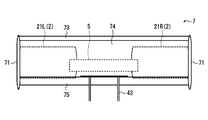
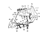
- the main wing 7 includes, for example, a pair of support panels 71 and 71 fixed to both side portions of the propelling device 2, and a main wing body 72 disposed between the support panels 71 and 71.
- the slat wing 73 is disposed in front of the main wing body 72
- the flap wing 74 is disposed in the rear of the main wing body 72.
- the slat wings 73 and the flap wings 74 are not essential components for the main wing body 72, and both may be omitted or only one of them may be arranged.
- the support panel 71 is made of, for example, a thin plate member having a streamline shape, and is fixed to the outer surface of the duct 21a of the ducted fans 21L and 21R. Note that the shape of the support panel 71 is not limited to the illustrated shape, and may be any other shape as long as aerodynamic resistance is taken into consideration. Although not shown, the support panel 71 may be fixed to the subframe 5.
- the main wing body 72 has, for example, a wing-shaped cross section as shown in FIG. 1A, and is arranged and fixed so as to be spanned between the support panels 71 and 71 as shown in FIG. 1C.
- the main wing body 72 has a surface area capable of generating lift necessary to glide the vertical take-off and landing aircraft 1 against gravity relative to the weight of the vertical take-off and landing aircraft 1 and the loaded weight (total weight of passengers and luggage). ing.
- the surface area of the main wing body 72 is appropriately changed according to conditions such as the weight of the vertical take-off and landing aircraft 1 and the maximum load weight. In order to increase the surface area of the main wing body 72, the lateral width of the main wing body 72 may be increased and the support panel 71 may be penetrated.
- the slat wing 73 is a kind of high lift device for increasing the lift of the aircraft.
- the slat wings 73 are arranged so as to form a certain gap with the front edge of the main wing body 72, for example. By disposing such slat wings 73, a part of the airflow passing through the lower surface side of the slat wings 73 can flow to the upper surface side of the main wing main body 72, and the separation of the airflow can be delayed.
- the slat wings 73 are not limited to fixed wings, and may be configured to be stored in the main wing body 72 during cruise flight.
- the flap wing 74 is also a kind of high lift device for increasing the lift of the aircraft.
- the flap blade 74 is disposed so as to form a certain gap with the rear edge of the main wing body 72.
- the flap wing 74 having such a configuration is called a slotted flap, and can make the camber of the main wing main body 72 longer, and a part of the airflow passing through the lower surface side of the main wing main body 72 flows to the upper surface side of the flap wing 74. Airflow separation can be delayed.
- the flap wings 74 are not limited to fixed wings, and may be configured such that the angle can be changed according to the flight state, or configured to be stored in the main wing body 72 during cruise flight. It may be.
- the main wing body 72 is disposed behind the propulsion device 2 (ducted fans 21L and 21R) with the propulsion device 2 (ducted fans 21L and 21R) facing vertically upward. It is configured as follows. That is, the main wing body 72 is disposed such that the chord direction is substantially parallel to the rotation axis of the ducted fans 21L and 21R. With this configuration, the main wing 7 does not interfere with the airflow passing through the ducted fans 21L and 21R.
- the main wing body 72 is disposed so as to have a certain gap between the main wing body 72 and the propulsion device 2 (ducted fans 21L and 21R). Specifically, the main wing body 72 has a certain clearance from the duct 21a of the ducted fans 21L and 21R and the power supply means 3 (exhaust nozzle 32, etc.). By forming such a gap, air current can flow between the propulsion device 2 (ducted fans 21L and 21R) and the main wing body 72 during gliding, and lift can be generated. This gap is appropriately set according to conditions such as the weight of the fuselage and the size of the main wing body 72.
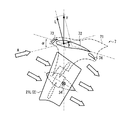
- FIG. 2A shows the action during cruise flight
- FIG. 2B shows the action in the thrust loss state during cruise flight
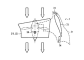
- FIG. 3A shows the action during hovering
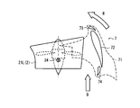
- FIG. 3B shows the action in the thrust loss state during hovering.
- the configuration other than the ducted fan 21L and the main wing 7 is omitted, and the support panel 71 is indicated by a one-dot chain line.
- the ducted fan 21L is steered forward with the power transmission shaft 34 as the center of rotation, and sucks air from the front and moves backward. Thrust is generated by blowing out.
- the main wing 7 is disposed above the ducted fan 21L, and the main wing main body 72 has an angle of attack of ⁇ with respect to the airflow A generated by the thrust of the ducted fan 21L.
- the airflow A passes through the gap between the main wing body 72 and the ducted fan 21L, and the main wing body 72 generates lift L (lift) and drag D (drag). Therefore, the aircraft body is lifted upward by the resultant force F, and the main wing 7 assists the flight of the vertical take-off and landing aircraft 1.
- the thruster 2 loses thrust.
- the main wing 7 that receives the airflow A and generates the lift L is provided, the main wing main body while the vertical take-off and landing aircraft 1 is flying by inertial force.
- the upward resultant force F that opposes the gravity of the vertical take-off and landing aircraft 1 can be generated by the airflow A that passes through the gap between the duct 72 and the ducted fan 21L.
- the vertical take-off and landing aircraft 1 can be safely and temporarily landed at a desired location.
- the vertical take-off and landing aircraft 1 can be turned by changing the weight of the occupant, and the traveling direction can be arbitrarily changed.
- the ducted fan 21L is driven in a state of being directed vertically upward with the power transmission shaft 34 as a rotation center, and sucks air from above to move downward. Thrust is generated by blowing out.
- the main wing 7 is arranged behind (in the back of) the ducted fan 21L, and is retracted to a position where it does not interfere with the airflow of the ducted fan 21L.
- the vertical take-off and landing aircraft 1 can be slid while avoiding the vertical take-off and landing aircraft 1 from falling vertically, as in the case of cruise flight.
- the vertical take-off and landing aircraft 1 can be safely landed at the place.
- the main wing 7 is arranged in the propulsion device 2 so that the propulsion device 2 can be rotated in conjunction with the propulsion device 2 at normal times (for example, during cruise flight or When hovering or the like) can be retracted to a position where it does not interfere with the airflow of the propulsion device 2, and when thrust is lost, it can be moved to a position where lift L is generated. Therefore, even if the propulsion device 2 loses thrust due to an engine trouble or the like, the main wing 7 can use the airflow A to generate the lift L and glide the airframe, thereby suppressing the vertical drop. be able to. Moreover, since it is only necessary to arrange the main wings 7 on the propulsion device 2, it is possible to suppress an increase in the size of the airframe.
- FIG. 4A is a side view showing the vertical take-off and landing aircraft according to the second embodiment of the present invention
- FIG. 4B is a side view showing the vertical take-off and landing aircraft according to the third embodiment.
- symbol is attached
- the propulsion device 2 may include control blades 8 that are configured by the ducted fans 21L and 21R and that control the flow direction of the airflow passing through the ducted fans 21L and 21R.
- the control wings 8 are arranged along the left and right directions of the ducted fans 21L and 21R. Specifically, a rotating shaft 81 is stretched between the duct 21a and the tail cone 21d of the ducted fans 21L and 21R, and the control blade 8 is fixed to the rotating shaft 81. Although not shown, one end of the rotation shaft 81 is rotatably supported by a bearing portion formed in the duct 21a, and the other end is connected to an actuator disposed in the tail cone 21d. Therefore, the control blade 8 can be rotated back and forth by rotating the rotation shaft 81.
- control wings 8 may be arranged on both the left and right sides of the tail cone 21d, or may be arranged only on either the inner side or the outer side. Further, the control blade 8 may be disposed so as to be exposed to the outside of the duct 21a, may be disposed so as to be accommodated in the duct 21a, or upstream of the propeller 21b of the ducted fans 21L and 21R. May be arranged.
- the control wings 8 are arranged in the front-rear direction of the ducted fans 21L and 21R. Specifically, a rotating shaft 81 is stretched along the left-right direction in the duct 21 a of the ducted fans 21 ⁇ / b> L and 21 ⁇ / b> R, and the control blade 8 is fixed to the rotating shaft 81.
- the rotating shaft 81 is rotatably supported at one end by a bearing portion formed in the duct 21a, and the other end is connected to an actuator disposed in the duct 21a. Therefore, the control blade 8 can be rotated back and forth by rotating the rotation shaft 81.
- control blades 8 may be disposed on both the front and rear sides of the tail cone 21d, or may be disposed only on either the front side or the rear side. Further, the control blade 8 may be disposed so as to be accommodated inside the duct 21a, may be disposed so as to be exposed to the outside of the duct 21a, or upstream of the propeller 21b of the ducted fans 21L and 21R. May be arranged.
- the flow of the airflow passing through the ducted fans 21L and 21R can be controlled by manipulating the rotation of the control blade 8, and thrust can be applied in a desired direction.
- the traveling direction of the vertical take-off and landing aircraft 1 is controlled by controlling the flow direction of the air flow.
- the vertical take-off and landing aircraft 1 can be steered toward a place suitable for emergency landing.
- a first aspect of the vertical take-off and landing aircraft includes a propulsion unit that generates lift and thrust, a main frame that supports a seat and a grounding leg, a propulsion unit that supports the propulsion unit and a longitudinal direction with respect to the main frame.
- a subframe that is pivotally disposed on the main frame, a power supply means that is supported by the main frame or the subframe and supplies power to the propulsion device, a control stick connected to the subframe, and the propulsion
- a main wing arranged on the sub-frame or the sub-frame, and the main wing is normally retracted to a position where it does not interfere with the air flow of the propellant and is movable to a position where lift is generated when thrust is lost It is supposed to be.
- the main wings are arranged in the propeller or subframe, so that the propeller can be rotated in conjunction with the propeller, for example, during cruise flight or hovering, the airflow of the propeller Can be retreated to a position where it does not interfere with, and when thrust is lost, it can be moved to a position where lift is generated.
- the main wing can use the airflow to generate lift and glide the aircraft, so that vertical fall can be suppressed. Become. Moreover, since it is only necessary to arrange the main wings on the propulsion unit or the subframe, the increase in size of the airframe can be suppressed.
- the main wing is configured by a pair of support panels fixed to both side portions of the propulsion device and a main wing body disposed between the support panels.
- the main wing body since both sides of the main wing body are respectively fixed to the pair of support panels, the main wing body has a high structural strength.
- the main wing is configured such that the main wing main body is arranged behind the propulsion unit with the propulsion unit facing vertically upward.
- the main wing can be prevented from interfering with the airflow passing through the propeller.
- the main wing body is disposed so as to have a certain gap between the main wing body and the propeller.
- the main wing includes at least one of a slat wing disposed in front of the main wing body and a flap wing disposed in the rear of the main wing body. It has a configuration.
- the separation of the airflow from the main wing body can be delayed.
- the propulsion unit is constituted by a ducted fan, and has control blades for controlling the direction of airflow passing through the ducted fan.
- the flow of the airflow passing through the propeller can be controlled, and the thrust can be generated in a desired direction.
Landscapes
- Engineering & Computer Science (AREA)
- Aviation & Aerospace Engineering (AREA)
- Mechanical Engineering (AREA)
- Toys (AREA)
- Transmission Devices (AREA)
Abstract
L'invention concerne un aéronef décollant et atterrissant verticalement comprenant : une hélice (2) qui génère de la portance et de la poussée ; un châssis principal (4) qui supporte un siège (41) et des patins de contact avec le sol (42) ; un faux-châssis (5) qui supporte l'hélice (2) et est disposé avec faculté de rotation dans une direction avant-arrière par rapport au châssis principal (4) ; un moyen d'alimentation en énergie (3) qui est supporté par le châssis principal (4) et alimente l'hélice (2) en énergie ; un manche à balai (6) qui est raccordé au faux-châssis (5) ; et une aile principale (7) qui est disposée dans l'hélice (2), l'aile principale (7) étant configurée pour se replier habituellement vers une position qui n'interfère pas avec un courant d'air généré par l'hélice (2), et lorsque la poussée est perdue, pour être capable de se déplacer vers une position dans laquelle la portance est générée. Par conséquent, le vol plané devient possible même lorsque la poussée est perdue pendant qu'une augmentation de la taille de son corps est supprimée.
Priority Applications (4)
| Application Number | Priority Date | Filing Date | Title |
|---|---|---|---|
| EP14798021.3A EP2998221B1 (fr) | 2013-05-16 | 2014-05-15 | Aéronef décollant et atterrissant verticalement |
| AU2014266242A AU2014266242B2 (en) | 2013-05-16 | 2014-05-15 | Vertical take-off and landing aircraft |
| NZ712963A NZ712963A (en) | 2013-05-16 | 2014-05-15 | Vertical take-off and landing aircraft |
| US14/886,481 US9994312B2 (en) | 2013-05-16 | 2015-10-19 | Vertical take-off and landing aircraft |
Applications Claiming Priority (2)
| Application Number | Priority Date | Filing Date | Title |
|---|---|---|---|
| JP2013-103898 | 2013-05-16 | ||
| JP2013103898A JP6213713B2 (ja) | 2013-05-16 | 2013-05-16 | 垂直離着陸機 |
Related Child Applications (1)
| Application Number | Title | Priority Date | Filing Date |
|---|---|---|---|
| US14/886,481 Continuation US9994312B2 (en) | 2013-05-16 | 2015-10-19 | Vertical take-off and landing aircraft |
Publications (1)
| Publication Number | Publication Date |
|---|---|
| WO2014185492A1 true WO2014185492A1 (fr) | 2014-11-20 |
Family
ID=51898467
Family Applications (1)
| Application Number | Title | Priority Date | Filing Date |
|---|---|---|---|
| PCT/JP2014/062955 WO2014185492A1 (fr) | 2013-05-16 | 2014-05-15 | Aéronef décollant et atterrissant verticalement |
Country Status (6)
| Country | Link |
|---|---|
| US (1) | US9994312B2 (fr) |
| EP (1) | EP2998221B1 (fr) |
| JP (1) | JP6213713B2 (fr) |
| AU (1) | AU2014266242B2 (fr) |
| NZ (1) | NZ712963A (fr) |
| WO (1) | WO2014185492A1 (fr) |
Families Citing this family (7)
| Publication number | Priority date | Publication date | Assignee | Title |
|---|---|---|---|---|
| US10822099B2 (en) | 2017-05-25 | 2020-11-03 | General Electric Company | Propulsion system for an aircraft |
| KR102186780B1 (ko) * | 2019-02-18 | 2020-12-04 | 박주현 | 비행부와 탑승부를 분리하여 축으로 결합한 유인드론 |
| PL3702277T3 (pl) * | 2019-02-27 | 2021-07-19 | Airbus Helicopters Deutschland GmbH | Wielowirnikowy statek powietrzny przystosowany do pionowego startu i lądowania (vtol) |
| CN109760830B (zh) * | 2019-03-20 | 2020-10-20 | 山东天衢精密工业有限公司 | 一种环境勘测用三撑腿模块组合式旋翼无人机 |
| CN109835463A (zh) * | 2019-04-16 | 2019-06-04 | 李则熙 | 一种涵道式自平衡隐形无人机 |
| JP6739779B1 (ja) * | 2020-03-25 | 2020-08-12 | 株式会社One Air | 個人用もしくは貨物用飛行デバイス |
| WO2024035714A1 (fr) * | 2022-08-09 | 2024-02-15 | Pete Bitar | Dispositif de livraison par drone compact et léger appelé système de drone à réacteur électrique arcspear ayant un système de propulsion à air canalisé électrique et étant relativement difficile à suivre en vol |
Citations (9)
| Publication number | Priority date | Publication date | Assignee | Title |
|---|---|---|---|---|
| JPH0577789A (ja) | 1991-09-20 | 1993-03-30 | Kawasaki Heavy Ind Ltd | 垂直離着陸航空機 |
| US5758844A (en) * | 1996-05-28 | 1998-06-02 | Boeing North American, Inc. | Vertical/short take-off and landing (V/STOL) air vehicle capable of providing high speed horizontal flight |
| JP2003509276A (ja) * | 1999-09-14 | 2003-03-11 | ユーロコプター | ロータ傾斜型転換式航空機における改良 |
| JP2006056364A (ja) | 2004-08-19 | 2006-03-02 | Toyota Motor Corp | 垂直離着陸機 |
| US20070158494A1 (en) * | 2004-01-08 | 2007-07-12 | Burrage Robert G | Tilt-rotor aircraft |
| JP2008531395A (ja) * | 2005-03-04 | 2008-08-14 | ジーエヌエム リミテッド | 推進装置 |
| US20080272226A1 (en) * | 2007-05-02 | 2008-11-06 | Honeywell International Inc. | Ducted Fan Air Vehicle with Deployable Wings |
| JP2013010466A (ja) * | 2011-06-30 | 2013-01-17 | Ihi Corp | 垂直離着陸機 |
| JP2013189104A (ja) * | 2012-03-14 | 2013-09-26 | Ihi Corp | 垂直離着陸機 |
Family Cites Families (18)
| Publication number | Priority date | Publication date | Assignee | Title |
|---|---|---|---|---|
| US3049320A (en) * | 1958-07-11 | 1962-08-14 | Charles J Fletcher | Annular wing aircraft |
| US3329376A (en) * | 1965-09-07 | 1967-07-04 | Paul D Sullivan | Short takeoff and landing aircraft |
| US3488018A (en) * | 1968-03-13 | 1970-01-06 | Us Navy | Ducted propulsion units for vtol aircraft |
| US3666209A (en) * | 1970-02-24 | 1972-05-30 | Boeing Co | V/stol aircraft with variable tilt wing |
| US3966142A (en) * | 1975-03-06 | 1976-06-29 | Grumman Aerospace Corporation | Vertical takeoff and landing aircraft |
| US4085911A (en) * | 1976-06-24 | 1978-04-25 | Grumman Aerospace Corporation | Vertical takeoff and landing aircraft |
| US5295643A (en) * | 1992-12-28 | 1994-03-22 | Hughes Missile Systems Company | Unmanned vertical take-off and landing, horizontal cruise, air vehicle |
| US6783096B2 (en) * | 2001-01-31 | 2004-08-31 | G. Douglas Baldwin | Vertical lift flying craft |
| WO2003004353A2 (fr) * | 2001-07-06 | 2003-01-16 | The Charles Stark Draper Laboratory, Inc. | Vehicule aerien a decollage et a atterrissage vertical |
| AU2002240223A1 (en) * | 2001-10-12 | 2003-04-28 | Gilbert Baldwin | Vertical lift flying craft with suspended payload |
| CA2489591A1 (fr) * | 2002-06-12 | 2003-12-24 | Thomas Sash | Commande d'un aeronef en tant que pendule oriente par la poussee en mode vertical, en mode horizontal et dans tous les modes de vol de transition entre ces derniers |
| US7472863B2 (en) * | 2004-07-09 | 2009-01-06 | Steve Pak | Sky hopper |
| CA2599342C (fr) | 2005-03-04 | 2014-05-27 | Gnm Limited | Dispositif de propulsion |
| US7753309B2 (en) * | 2007-03-22 | 2010-07-13 | Oliver Garreau | VTOL/STOL tilt-prop flying wing |
| US8256704B2 (en) * | 2007-08-14 | 2012-09-04 | Lapcad Engineering, Inc. | Vertical/short take-off and landing aircraft |
| US8162253B2 (en) * | 2009-08-19 | 2012-04-24 | Seiford Sr Donald S | Convertible vehicle for road, air, and water usage |
| WO2011146349A2 (fr) * | 2010-05-17 | 2011-11-24 | Piasecki Aircraft Corp. | Véhicule aérien modulaire et façonnable |
| US9637230B2 (en) * | 2013-03-15 | 2017-05-02 | Bertelsen Design LLC | Aircraft and convertible wing assembly |
-
2013
- 2013-05-16 JP JP2013103898A patent/JP6213713B2/ja not_active Expired - Fee Related
-
2014
- 2014-05-15 WO PCT/JP2014/062955 patent/WO2014185492A1/fr active Application Filing
- 2014-05-15 NZ NZ712963A patent/NZ712963A/en not_active IP Right Cessation
- 2014-05-15 AU AU2014266242A patent/AU2014266242B2/en not_active Ceased
- 2014-05-15 EP EP14798021.3A patent/EP2998221B1/fr not_active Not-in-force
-
2015
- 2015-10-19 US US14/886,481 patent/US9994312B2/en not_active Expired - Fee Related
Patent Citations (9)
| Publication number | Priority date | Publication date | Assignee | Title |
|---|---|---|---|---|
| JPH0577789A (ja) | 1991-09-20 | 1993-03-30 | Kawasaki Heavy Ind Ltd | 垂直離着陸航空機 |
| US5758844A (en) * | 1996-05-28 | 1998-06-02 | Boeing North American, Inc. | Vertical/short take-off and landing (V/STOL) air vehicle capable of providing high speed horizontal flight |
| JP2003509276A (ja) * | 1999-09-14 | 2003-03-11 | ユーロコプター | ロータ傾斜型転換式航空機における改良 |
| US20070158494A1 (en) * | 2004-01-08 | 2007-07-12 | Burrage Robert G | Tilt-rotor aircraft |
| JP2006056364A (ja) | 2004-08-19 | 2006-03-02 | Toyota Motor Corp | 垂直離着陸機 |
| JP2008531395A (ja) * | 2005-03-04 | 2008-08-14 | ジーエヌエム リミテッド | 推進装置 |
| US20080272226A1 (en) * | 2007-05-02 | 2008-11-06 | Honeywell International Inc. | Ducted Fan Air Vehicle with Deployable Wings |
| JP2013010466A (ja) * | 2011-06-30 | 2013-01-17 | Ihi Corp | 垂直離着陸機 |
| JP2013189104A (ja) * | 2012-03-14 | 2013-09-26 | Ihi Corp | 垂直離着陸機 |
Also Published As
| Publication number | Publication date |
|---|---|
| JP2014223846A (ja) | 2014-12-04 |
| EP2998221B1 (fr) | 2018-03-14 |
| AU2014266242A1 (en) | 2015-10-29 |
| US9994312B2 (en) | 2018-06-12 |
| EP2998221A1 (fr) | 2016-03-23 |
| NZ712963A (en) | 2016-08-26 |
| AU2014266242B2 (en) | 2016-04-07 |
| JP6213713B2 (ja) | 2017-10-18 |
| US20160114885A1 (en) | 2016-04-28 |
| EP2998221A4 (fr) | 2017-01-04 |
Similar Documents
| Publication | Publication Date | Title |
|---|---|---|
| EP2899122B1 (fr) | Avion à décollage et atterrissage vertical | |
| EP3684687B1 (fr) | Système d'actionnement d'inclinaison pour aéronef à décollage et atterrissage verticaux (adav) | |
| WO2014185492A1 (fr) | Aéronef décollant et atterrissant verticalement | |
| US9254916B2 (en) | Vertical take-off and landing aircraft with tiltrotor power for use on land and in air | |
| CN106573678B (zh) | 适于垂直起飞和水平飞行的飞行器 | |
| US6896221B1 (en) | Vertical takeoff and landing aircraft | |
| EP2738091B1 (fr) | Véhicule aérien pour décollage et atterrissage vertical (VTOL) et procédé de fonctionnement d'un tel véhicule aérien VTOL | |
| EP2727833B1 (fr) | Aéronef à décollage et atterrissage vertical | |
| US11472545B2 (en) | Propulsion system and aircraft with vertical take-off and landing-VTOL | |
| WO2013137261A1 (fr) | Dispositif de décollage et d'atterrissage vertical | |
| JP2009045986A (ja) | ヘリコプタ | |
| JP7478667B2 (ja) | 個人用垂直離着陸飛行装置 | |
| US20040232279A1 (en) | VTOL/STOL ducted propeller aircraft | |
| JP2009541124A (ja) | 切り替え可能な飛行システムを有する航空機 | |
| JP2011162173A (ja) | 垂直離着陸飛行機 | |
| EP3181445B1 (fr) | Élément de plaque destiné à réduire la traînée sur un carénage d'avion | |
| KR20090054027A (ko) | 가변형 회전익을 이용한 수직이착륙기 | |
| GB2504369A (en) | Aircraft wing with reciprocating outer aerofoil sections | |
| EP3805100B1 (fr) | Aéronef adav | |
| US8944366B2 (en) | Rotorcraft empennage mounting system | |
| JP2010042792A (ja) | 多機能飛行機 | |
| NZ619528B2 (en) | Vertical take-off and landing aircraft |
Legal Events
| Date | Code | Title | Description |
|---|---|---|---|
| 121 | Ep: the epo has been informed by wipo that ep was designated in this application |
Ref document number: 14798021 Country of ref document: EP Kind code of ref document: A1 |
|
| ENP | Entry into the national phase |
Ref document number: 2014266242 Country of ref document: AU Date of ref document: 20140515 Kind code of ref document: A |
|
| WWE | Wipo information: entry into national phase |
Ref document number: 2014798021 Country of ref document: EP |
|
| NENP | Non-entry into the national phase |
Ref country code: DE |