WO2014185448A1 - 金型、及び金型の製造方法 - Google Patents
金型、及び金型の製造方法 Download PDFInfo
- Publication number
- WO2014185448A1 WO2014185448A1 PCT/JP2014/062816 JP2014062816W WO2014185448A1 WO 2014185448 A1 WO2014185448 A1 WO 2014185448A1 JP 2014062816 W JP2014062816 W JP 2014062816W WO 2014185448 A1 WO2014185448 A1 WO 2014185448A1
- Authority
- WO
- WIPO (PCT)
- Prior art keywords
- mold
- insulating layer
- heat insulating
- runner
- heat
- Prior art date
- Legal status (The legal status is an assumption and is not a legal conclusion. Google has not performed a legal analysis and makes no representation as to the accuracy of the status listed.)
- Ceased
Links
Images

Classifications
-
- B—PERFORMING OPERATIONS; TRANSPORTING
- B29—WORKING OF PLASTICS; WORKING OF SUBSTANCES IN A PLASTIC STATE IN GENERAL
- B29C—SHAPING OR JOINING OF PLASTICS; SHAPING OF MATERIAL IN A PLASTIC STATE, NOT OTHERWISE PROVIDED FOR; AFTER-TREATMENT OF THE SHAPED PRODUCTS, e.g. REPAIRING
- B29C45/00—Injection moulding, i.e. forcing the required volume of moulding material through a nozzle into a closed mould; Apparatus therefor
- B29C45/17—Component parts, details or accessories; Auxiliary operations
- B29C45/26—Moulds
- B29C45/27—Sprue channels ; Runner channels or runner nozzles
- B29C45/2756—Cold runner channels
-
- B—PERFORMING OPERATIONS; TRANSPORTING
- B22—CASTING; POWDER METALLURGY
- B22C—FOUNDRY MOULDING
- B22C9/00—Moulds or cores; Moulding processes
- B22C9/08—Features with respect to supply of molten metal, e.g. ingates, circular gates, skim gates
-
- B—PERFORMING OPERATIONS; TRANSPORTING
- B22—CASTING; POWDER METALLURGY
- B22D—CASTING OF METALS; CASTING OF OTHER SUBSTANCES BY THE SAME PROCESSES OR DEVICES
- B22D17/00—Pressure die casting or injection die casting, i.e. casting in which the metal is forced into a mould under high pressure
- B22D17/20—Accessories: Details
- B22D17/22—Dies; Die plates; Die supports; Cooling equipment for dies; Accessories for loosening and ejecting castings from dies
-
- B—PERFORMING OPERATIONS; TRANSPORTING
- B29—WORKING OF PLASTICS; WORKING OF SUBSTANCES IN A PLASTIC STATE IN GENERAL
- B29C—SHAPING OR JOINING OF PLASTICS; SHAPING OF MATERIAL IN A PLASTIC STATE, NOT OTHERWISE PROVIDED FOR; AFTER-TREATMENT OF THE SHAPED PRODUCTS, e.g. REPAIRING
- B29C45/00—Injection moulding, i.e. forcing the required volume of moulding material through a nozzle into a closed mould; Apparatus therefor
- B29C45/17—Component parts, details or accessories; Auxiliary operations
- B29C45/26—Moulds
- B29C45/27—Sprue channels ; Runner channels or runner nozzles
- B29C2045/2795—Insulated runners
Definitions
- the present invention relates to a mold and a method for manufacturing the mold.
- Thermoplastic resins are used in a wide range of fields such as interior parts and housings of home appliances, exterior and interior parts of automobiles, etc. because of their excellent moldability and relatively high physical properties such as mechanical strength.
- a molded product made of a thermoplastic resin is manufactured by injection-molding a thermoplastic resin with an injection mold.
- a sprue connected to the injection molding machine and a runner portion having one end connected to the sprue and the other end connected to the cavity via a gate are formed.
- the sprue refers to the molten resin inflow passage from the portion in contact with the nozzle of the injection molding machine to the runner
- the runner refers to the intermediate passage of the molten resin from the sprue to the gate.
- An inlet through which molten resin flows from the runner into the cavity That is, the resin injected from the injection molding machine flows into the runner portion from the sprue and is filled into the cavity from the gate via the runner portion.
- Patent Document 1 An injection mold apparatus in which a heat insulation layer is formed on a cold runner is known (Patent Document 1).
- the cold runner has a substantially semicircular cross section formed on a split surface of one mold element among a pair of mold elements that are opened when a molded product is taken out.
- the groove portion is formed with a dividing surface of the other mold element, and a heat insulating layer is formed in the groove portion, and the thickness of the heat insulating layer gradually increases toward the dividing surface of the other mold element. It is gradually changed to become smaller. That is, the thickness of the heat insulating layer is the thickest at the deepest portion of the cold runner, and is thinner as it is closer to the dividing surface, and is not constant.
- the thickness of the injection molded product is the same, if the thickness of the heat insulating layer formed on the inner surface of the mold is different, the flow length of the molten thermoplastic resin, that is, the flow Gender was found to be different.
- a molded product having a thickness of 0.3 mm or 0.5 mm is formed using a mold having a heat insulation layer thickness of 0.5 mm, a mold having a heat insulation layer thickness of 0.7 mm is used.
- the flow length of the molten thermoplastic resin is about 10% shorter compared to the case where the molded product having the same thickness is molded, and the thinner the heat insulating layer formed on the inner surface of the mold, It has been found that the fluidity of the plastic resin deteriorates. Thus, if there is a thin part in the heat insulation layer, the fluidity of the thermoplastic resin will deteriorate in that part. That is, in order to improve the fluidity, the thickness of the heat insulating layer may be increased. However, if the thick and thin portions coexist in the heat insulating layer, the fluidity is influenced by the thin portion. The improvement effect will be impaired.
- the present invention has been made in order to solve the above problems, and its purpose is to sufficiently secure the fluidity of the thermoplastic resin in the runner portion during injection molding, and to provide heat insulation formed in the runner portion.
- the object is to provide a technique for solving inconveniences such as lack of layers.
- the inventors of the present invention have made extensive studies to solve the above problems.
- a heat insulating layer is provided on the inner surface of the mold forming the runner portion, and the heat insulating layer within a certain range has a thickness within a predetermined range.
- the heat insulation layer formed on the first mold and the heat insulation layer formed on the second mold are arranged so as not to contact each other, and the above problem is solved.
- the present invention has been completed. More specifically, the present invention provides the following.
- a mold having a cavity for forming and a runner part for forming a runner, wherein the inner surface of the mold forming the runner part in the first mold and the second mold is insulated.
- the ratio of the thickness of the heat insulating layer and the maximum thickness of the heat insulating layer on the outer periphery is calculated along the outer periphery of the runner part on a cross section perpendicular to the longitudinal direction of the runner,
- the length of the portion on the outer periphery where the ratio is 0.56 to 1.00 is not less than 80% and less than 100% with respect to the length of the outer periphery, and the length formed on the first mold
- the heat insulating layer and the heat insulating layer formed on the second mold are arranged so as not to contact each other. Mold.
- At least a part of the runner part is provided in the first mold or the second mold, and has a groove part having an opening on a mold mating surface between the first mold and the second mold.
- the heat insulating layer provided on the surface of the groove portion, provided that a chamfered portion in which the heat insulating layer or the heat insulating layer and the groove portion are chamfered by an inclined surface is formed adjacent to the opening.
- the outer angle ⁇ formed by the inclined surface and the mold mating surface satisfies 0 ° ⁇ ⁇ 45 °.
- At least a part of the runner part is provided in the first mold or the second mold, and has a groove part having an opening on a mold mating surface between the first mold and the second mold.
- the heat insulating layer provided on the surface of the groove part provided that there is a heat insulating layer between the heat insulating layer provided on the surface of the groove part and the extended surface of the mold mating surface.
- the fluidity of the thermoplastic resin can be sufficiently ensured in the runner portion at the time of injection molding, and since the heat insulating layer formed on the runner portion does not come in contact with the die mating surface, Problems such as missing layers are less likely to occur.
- FIG. 1 is a diagram schematically showing a mold according to the first embodiment of the present invention.
- the mold 1 of the present embodiment includes a first mold 2 and a second mold 3 disposed to face the first mold 2. Between the two molds 3, a cavity 4 for forming the shape of the molded product, a gate 5, and a runner portion 6 for forming a runner are provided.
- the first heat insulating layer 7 on the first mold 2 side and the second surface are formed on the inner surface of the mold forming the runner portion 6 in the first mold 2 and the second mold 3.
- a second heat insulating layer 8 on the mold 3 side is provided.
- the first mold 2 has a sprue S.
- Molten resin is supplied to the portion indicated by the circle in FIG.
- the “inside surface of the mold” refers to a wall surface of the mold that is in contact with the resin, directly or through a heat insulating layer.
- “Cavity” refers to the entire space filled with resin inside the mold.
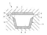
- FIG. 2 is an enlarged sectional view showing the periphery of the runner portion in the AA section of FIG. 1 (that is, a section perpendicular to the longitudinal direction of the runner).
- the ratio between the thickness of the first heat insulating layer 7 or the second heat insulating layer 8 and the maximum thickness of the first heat insulating layer 7 and the entire second heat insulating layer 8 on the outer periphery along the outer periphery of the runner part 6, the ratio between the thickness of the first heat insulating layer 7 or the second heat insulating layer 8 and the maximum thickness of the first heat insulating layer 7 and the entire second heat insulating layer 8 on the outer periphery.
- the length of the portion on the outer periphery where this ratio is 0.56 to 1.00, preferably 0.70 to 1.00, more preferably 0.80 to 1.00 is calculated as The first mold 2 and the second mold 3 are formed so that the length is 80% or more and less than 100%, preferably 90% or more and less than 100%.
- the thickness of the heat insulating layer depends on the position. Since the fluctuation is small and the thick portion and the thin portion are difficult to coexist, the fluidity of the molten thermoplastic resin is easily kept uniform in the runner portion 6.
- die 3 are arrange
- the runner portion 6 is provided in the first mold 2 where the first heat insulating layer 7 is formed, and the second mold 3, and the first mold 2, the second mold 3, It is formed from a groove portion 11 having an opening 10 on the mold mating surface 9 and a second heat insulating layer 8 provided on the surface of the groove portion 11.
- a second heat insulating layer 8 having a constant thickness is provided on the surface of the groove 11, but a chamfered portion 12 in which the second heat insulating layer 8 and the groove 11 are chamfered by an inclined surface is adjacent to the opening 10. Since it is formed, the thickness of the second heat insulating layer 8 adjacent to the chamfered portion 12 is thinner.
- a first heat insulating layer 7 is formed on the inner surface of the first mold 2 forming the runner portion 6.
- the first heat insulating layer 7 has a constant thickness except for both ends, and the thickness gradually decreases at both ends.
- the thickness of the first heat insulation layer 7 and the thickness of the second heat insulation layer 8 are set to be the same.
- the thickness of the first heat insulating layer 7 and the second heat insulating layer 8 is not particularly limited, but is preferably 50 to 1000 ⁇ m. When the thickness is within this range, the heat insulating effect by the first heat insulating layer 7 and the second heat insulating layer 8 is easily exhibited.
- the said thickness is 1000 micrometers or less, it is preferable for the reason that a shaping
- the outer angle ⁇ formed by the inclined surface forming the chamfered portion 12 and the die mating surface 9 satisfies 0 ° ⁇ ⁇ 45 °, preferably 5 ° ⁇ ⁇ ⁇ 10 °.
- the range in which the second heat insulating layer 8 is not formed is suppressed to be sufficiently small, so that the heat insulating effect by the first heat insulating layer 7 and the second heat insulating layer 8 is hardly impaired.
- the distance x satisfies 0 mm ⁇ x ⁇ 1.0 mm, preferably 0.1 mm ⁇ x ⁇ 0.3 mm.
- the range in which the second heat insulating layer 8 is not formed is suppressed to be sufficiently small, so that the heat insulating effect by the first heat insulating layer 7 and the second heat insulating layer 8 is hardly impaired.
- required by the 1st heat insulation layer 7 and the 2nd heat insulation layer 8 changes with uses etc., it is especially preferable that it is 2 W / m * K or less.
- the material which comprises the 1st heat insulation layer 7 and the 2nd heat insulation layer 8 is not specifically limited, If it has heat resistance of the grade which does not produce a malfunction even if it has low heat conductivity and a high temperature resin composition contacts. That's fine.
- a resin having high heat resistance such as polyimide resin and low heat conductivity, and porous ceramic such as porous zirconia are used. It can be illustrated. Hereinafter, these materials will be described.
- polyimide resin examples include pyromellitic acid (PMDA) -based polyimide, biphenyltetracarboxylic acid-based polyimide, polyamideimide using trimellitic acid, bismaleimide-based resin (bismaleimide / triazine-based, etc.), benzophenone tetracarboxylic acid Based polyimide, acetylene-terminated polyimide, thermoplastic polyimide, and the like.
- Preferable materials other than polyimide resin include, for example, tetrafluoroethylene resin.
- the heat insulating layer may contain a resin other than polyimide resin and tetrafluoroethylene resin, additives, and the like as long as the effects of the present invention are not impaired.
- the zirconia contained in the porous zirconia is not particularly limited, and may be any of stabilized zirconia, partially stabilized zirconia, and unstabilized zirconia.
- Stabilized zirconia is one in which cubic zirconia is stabilized even at room temperature, and is excellent in mechanical properties such as strength and toughness and wear resistance.
- Partially stabilized zirconia refers to a state in which tetragonal zirconia partially remains even at room temperature, and when subjected to external stress, a martensitic transformation from tetragonal to monoclinic occurs, and is particularly advanced by the action of tensile stress. Suppresses crack growth and has high fracture toughness.
- Unstabilized zirconia refers to zirconia that is not stabilized by a stabilizer. In addition, you may use combining at least 2 or more types selected from stabilized zirconia, partially stabilized zirconia, and unstabilized zirconia.
- the stabilizer contained in the stabilized zirconia and the partially stabilized zirconia conventionally known general ones can be employed.
- yttria, ceria, magnesia and the like can be mentioned.
- the amount of the stabilizer used is not particularly limited, and the amount used can be appropriately set according to the application, the material used, and the like.
- porous ceramics other than porous zirconia can be used, but porous zirconia has higher durability than other porous ceramics. For this reason, if the metal mold
- the raw material for forming the first heat insulating layer 7 and the second heat insulating layer 8 may further include conventionally known additives in addition to the above-mentioned zirconia and stabilizer as long as the effects of the present invention are not impaired.
- die 1 which concerns on 1st embodiment of this invention is the heat insulation which forms the 2nd heat insulation layer 8 in the surface of the groove part 11 in which the 2nd heat insulation layer 8 is not formed and the chamfering part 12 is not formed. It can be obtained by a mold manufacturing method including at least a layer forming step and a chamfered portion forming step of grinding the second heat insulating layer 8 and the groove portion 11 to form the chamfered portion 12.
- die 2 in which the 1st heat insulation layer 7 is not formed is also performed.
- the heat insulating layer can be formed using the above-described raw materials.
- the method for forming the heat insulating layer using the above raw materials is not particularly limited, but it is preferable to employ a thermal spraying method.
- the thermal spraying method By adopting the thermal spraying method, the thermal conductivity of porous zirconia can be easily adjusted to a desired range. Moreover, problems such as a significant decrease in the mechanical strength of the heat insulating layer due to excessive formation of bubbles inside the porous zirconia do not occur.
- the structure of a heat insulation layer becomes a thing suitable for the use of this invention.
- Formation of the heat insulation layer by thermal spraying can be performed as follows, for example. First, the raw material for the heat insulating layer is melted to form a liquid. The liquid is accelerated and collides with a desired inner surface of the mold. Finally, the raw material that collides with and adheres to the desired inner surface of the mold is solidified. By doing in this way, a very thin heat insulation layer is formed. The thickness of the heat insulating layer can be adjusted by allowing the melted raw material to collide with the very thin heat insulating layer and solidify. As a method for solidifying the raw material, a conventionally known cooling means may be used, or the raw material may be solidified simply by leaving it to stand. The thermal spraying method is not particularly limited, and a preferable method can be appropriately selected from conventionally known methods such as arc spraying, plasma spraying, and flame spraying.
- the chamfered portion 12 can be formed by grinding into a predetermined shape in a chamfered portion forming step performed after forming the first heat insulating layer 7 and the second heat insulating layer 8 without forming the chamfered portion 12. it can.
- the grinding method in the chamfered portion forming step is not particularly limited. However, if the surface to be polished is a flat surface, it is removed so as to gradually scrape by a lapping method (mechanical polishing). It is preferable to do.
- a diamond grindstone can be used for the manual polishing method.
- mechanical polishing for example, diamond abrasive grains or diamond paste in which diamond abrasive grains are dispersed in a dispersion medium can be used.
- the thickness of the first heat insulating layer 7 and the second heat insulating layer 8 is constant except for the vicinity of the chamfered portion 12. Therefore, the fluidity of the molten thermoplastic resin is easily maintained in the runner portion 6.
- the first heat insulating layer 7 and the second heat insulating layer 8 do not contact each other.
- the first heat-insulating layer 7 and the second heat-insulating layer 8 are difficult to come into contact with other members when the mold is opened and closed, and problems such as lack of the heat-insulating layer are less likely to occur.
- the chamfered portion 12 can be easily formed by a conventionally known processing method as described above.
- the shape of the runner portion 6 is slightly changed, and a burr is easily generated.
- the runner portion 6 is not particularly problematic because even if the shape changes to some extent or even a few burrs are produced, the influence on the final molded product is very small.
- the mold 1A according to the second embodiment of the present invention is the first of the present invention except that the periphery of the runner portion in the cross section corresponding to the AA cross section of FIG. 1 is represented in FIG. 3 instead of FIG. This is the same as the mold 1 according to the embodiment. Below, a difference with the metal mold
- FIG. 3 is an enlarged sectional view showing the periphery of the runner part in the mold according to the second embodiment of the present invention.
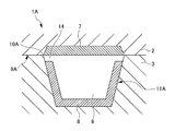
- FIG. 3 unlike FIG. 2, there is no gap between the second heat insulating layer 8 provided on the surface of the groove 11 ⁇ / b> A and the extended surface of the die mating surface 9 ⁇ / b> A of the second mold 3. 14 is formed.
- the thickness of the 1st heat insulation layer 7 or the 2nd heat insulation layer 8 and the 1st heat insulation layer 7 and the 2nd heat insulation layer 8 on the said outer periphery are followed along the outer periphery of the runner part 6 similarly to FIG.
- the portion on the outer periphery where the ratio is 0.56 to 1.00, preferably 0.70 to 1.00, more preferably 0.80 to 1.00 The first mold 2 and the second mold 3 are formed so that the length is 80% or more and less than 100%, preferably 90% or more and less than 100%, with respect to the length of the outer periphery.
- the thickness of the heat insulating layer depends on the position. Since the fluctuation is small and the thick portion and the thin portion are difficult to coexist, the fluidity of the molten thermoplastic resin is easily kept uniform in the runner portion 6.
- the height of the gap 14, that is, the distance from the upper end of the second heat insulating layer 8 to the first mold 2 is preferably 0.03 to 0.3 mm. If this distance is in the above range, the range in which the second heat insulating layer 8 is not formed is suppressed to be sufficiently small, so that the heat insulating effect by the first heat insulating layer 7 and the second heat insulating layer 8 is hardly impaired.
- the gap can be obtained by a mold manufacturing method including at least a gap forming step for forming the gap 14.
- die 2 in which the 1st heat insulation layer 7 is not formed is also performed.
- the heat insulation layer can be formed in the same manner as described in the first embodiment.
- the gap 14 can be formed by grinding into a predetermined shape in a gap forming step performed after forming the first heat insulation layer 7 and the second heat insulation layer 8 without forming the gap 14.
- the grinding method in the gap forming step is as described in the first embodiment.
- the thickness of the first heat insulation layer 7 and the second heat insulation layer 8 is constant except for the vicinity of the gap 14. Therefore, the fluidity of the molten thermoplastic resin is easily maintained in the runner portion 6.
- the gap 14 is formed as described above, the first heat insulation layer 7 and the second heat insulation layer 8 do not contact each other.
- the first heat-insulating layer 7 and the second heat-insulating layer 8 are difficult to come into contact with other members when the mold is opened and closed, and problems such as lack of the heat-insulating layer are less likely to occur.
- the mold 1A according to the second embodiment of the present invention unlike the mold 1 according to the first embodiment of the present invention, a chamfered portion is provided at the contact portion between the first mold 2 and the second mold 3. There is no gap due to forming 12. For this reason, the mold 1A is theoretically expected to have less loss in mold rigidity than the mold 1.
- the gap 14 can be easily formed by a conventionally known processing method as described above.
- the shape of the runner portion 6 is slightly changed and a burr is easily generated.
- the runner portion 6 having a trapezoidal cross-sectional shape has been described, but the shape of the runner portion 6 may be a semicircular shape, a semi-elliptical shape, an arc shape, or the like.
- die 3 was demonstrated, the runner part may be formed in the 1st metal mold
- the chamfered part 12 and the gap 14 are formed only on the first mold 2 side, but the second mold Even if it is formed only on the 3 side, it may be formed on both the first mold 2 side and the second mold 3 side.
- Crystalline thermoplastic resin Polyphenylene sulfide resin (PPS resin) (manufactured by Polyplastics Co., Ltd., “DURAFIDE (registered trademark) 1140A6”)
- Heat insulation layer A raw material mainly composed of zirconia was sprayed on the metal surface of the mold by a thermal spraying method to form a heat insulation layer, thereby obtaining a heat insulation mold.
- the thickness of the formed heat insulation layer is three types, 1.00, 0.71, and 0.43 in relative value.
- die has a dimension of width 5mm and thickness 0.5mm.
- a cylinder-shaped product having a width of 5 mm and a thickness of 0.5 mm is injection-molded under the conditions of a cylinder temperature of 320 ° C., an injection pressure of 100 MPa, 75 MPa, or 50 MPa and a mold temperature of 180 ° C. or 170 ° C.
- the flow distance was measured.
- the average value in five tests is shown in Table 1 as a relative value.
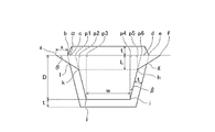
- the outer periphery of the runner portion 6 is formed by connecting points a, b, c, d, e, f, g, h, i, j, k, l, and a in FIG. In FIG. 4, hatching is omitted for easy viewing.
- the length of the outer periphery of the runner portion 6 was calculated.
- the lengths of the line segment ab and the line segment ef are x.
- the length of the line segment be is the sum of the lengths of the line segment bp1, the line segment p1p3, the line segment p3p4, the line segment p4p6, and the line segment p6e.
- the lengths of the line segment bp1 and the line segment p6e are t / cos ⁇ .
- the lengths of the line segment p1p3 and the line segment p4p6 are Dtan ⁇ .
- the length of the line segment p3p4 is W.
- the length of the line segment be is 2t / cos ⁇ + 2Dtan ⁇ + W.
- the lengths of the line segment fh and the line segment ka are represented by L / sin ⁇ .
- the length of the line segment p5p6 is Ltan ⁇
- the lengths of the line segment fh and the line segment ka are (t / cos ⁇ + x) / (cos ⁇ tan ⁇ sin ⁇ ).
- the lengths of the line segment hi and the line segment jk are represented as (DL) / cos ⁇ , and L is represented as described above. Therefore, the lengths of the line segment hi and the line segment jk are D / cos ⁇ - (t / cos ⁇ + x) tan ⁇ / (cos ⁇ -sin ⁇ tan ⁇ ).
- the length of the line segment ij is W.
- the length of the outer circumference of the runner 6 is the sum of the lengths of the line segment ab, line segment be, line segment ef, line segment fh, line segment hi, line segment ij, line segment jk, and line segment ka. Therefore, 2x + 2 (t + D) / cos ⁇ + 2Dtan ⁇ + 2W + 2 (t / cos ⁇ + x) / (cos ⁇ tan ⁇ sin ⁇ ) ⁇ 2 (t / cos ⁇ + x) tan ⁇ / (cos ⁇ sin ⁇ tan ⁇ ) is calculated.
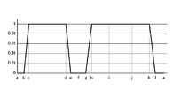
- the thickness of the first heat insulating layer 7 or the second heat insulating layer 8 is shown in a graph along the outer periphery of the runner portion 6. The results are shown in FIG. As can be seen from FIG. 5, the maximum thickness of the entire first heat insulating layer 7 and the second heat insulating layer 8 on the outer periphery is t.
- the thickness of the first heat insulating layer 7 or the second heat insulating layer 8 and the first heat insulating layer on the outer periphery. 7 and the length Z of the portion on the outer periphery where the ratio of the total thickness to the maximum thickness of the second heat insulating layer 8 is r or more and 1.00 or less (where r ⁇ 1.00) was calculated.
- the length Z is the length of the line segment bc ⁇ (1-r), the length of the line segment cd, the length of the line segment de ⁇ (1-r), and the length of the line segment gh.
- X (1-r) is the sum of the length of the line segment hk and the length of the line segment kl ⁇ (1-r).
- the lengths of the line segment bc and the line segment de are t / tan ⁇ . Since the length of the line segment cd is equal to the difference between the length of the line segment be and the sum of the lengths of the line segment bc and the line segment de, it is 2t / cos ⁇ + 2D tan ⁇ + W ⁇ 2t / tan ⁇ .
- the lengths of the line segment gh and the line segment kl are t / cos ⁇ / (t / cos ⁇ + x) ⁇ (t / cos ⁇ + x) / (cos ⁇ Since it is expressed as tan ⁇ sin ⁇ ), it is t / (cos ⁇ cos ⁇ -sin ⁇ sin ⁇ ). Since the length of the line segment hk is the sum of the lengths of the line segment hi, the line segment ij, and the line segment jk, it is 2D / cos ⁇ -2 (t / cos ⁇ + x) tan ⁇ / (cos ⁇ -sin ⁇ tan ⁇ ) + W. .
- the length Z is calculated as ⁇ 2rt / tan ⁇ + 2 (t + D) / cos ⁇ + 2Dtan ⁇ + 2W + 2 (1-r) t / (cos ⁇ cos ⁇ -sin ⁇ sin ⁇ ) -2 (t / cos ⁇ + x) tan ⁇ / (cos ⁇ -sin ⁇ tan ⁇ ).
- the length of the outer periphery of the runner portion 6 is 2x + 2 (t + D) + 2W + 2 (t + x) / cos ⁇ -2 (t + x)
- the length Z can be approximated to -2rt / tan ⁇ + 2 (t + D) + 2W + 2 (1-r) t / cos ⁇ -2 (t + x) tan ⁇ .
- the ratio (%) of the length Z with respect to the length of the outer periphery of the runner portion 6 was calculated by substituting the values of the respective parameters into the approximate expression. The results are shown in Tables 2-5.
- the first heat insulating layer 7 or the second heat insulating layer 8 is formed along the outer periphery of the runner portion 6 on the cross section perpendicular to the longitudinal direction of the runner.
- the first mold 2 and the second mold 3 can be formed so as to be 80% or more and less than 100%.
- ⁇ , x, r, t, D, W, ⁇ , And ⁇ are appropriately selected so that the ratio of the length Z to the outer peripheral length of the runner portion 6, that is, ⁇ 2rt / tan ⁇ + 2 (t + D) / cos ⁇ + 2Dtan ⁇ + 2W + 2 (1-r) t / (cos ⁇ cos ⁇ sin ⁇ sin ⁇ ) ⁇ 2 (t / cos ⁇ + x) tan ⁇ / (cos ⁇ sin ⁇ tan ⁇ ) ⁇ / ⁇ 2x + 2 (t + D) / cos ⁇ + 2Dtan ⁇ + 2W + 2 (t / cos ⁇ + x) / (cos ⁇ tan ⁇ sin ⁇ ) ⁇ 2 (t / cos ⁇ + x) tan ⁇ /
- the length of the outer periphery of the runner portion 6 is 2x + 2 (t + D) + 2W + 2 (t + x ) / Cos ⁇ -2 (t + x) tan ⁇ , and the length Z can be approximated as ⁇ 2 rt / tan ⁇ + 2 (t + D) + 2W + 2 (1-r) t / cos ⁇ -2 (t + x) tan ⁇ .
- ⁇ , x, r, t, D, W, and ⁇ are within the ranges of 0 ° ⁇ ⁇ 45 °, 0 mm ⁇ x ⁇ 1.0 mm, and 0.56 ⁇ r ⁇ 1.00.
- the first mold 2 and the second mold 3 are formed so that the value of / ⁇ 2x + 2 (t + D) + 2W + 2 (t + x) / cos ⁇ -2 (t + x) tan ⁇ ⁇ 100 is 80% or more and less than 100%. Can do.
Landscapes
- Engineering & Computer Science (AREA)
- Mechanical Engineering (AREA)
- Manufacturing & Machinery (AREA)
- Moulds For Moulding Plastics Or The Like (AREA)
Abstract
射出成形時のランナー部において熱可塑性樹脂の流動性を十分に確保し、また、ランナー部に形成された断熱層が欠ける等の不都合を解消する技術を提供する。 第一金型と、前記第一金型に対向配置される第二金型とを備え、前記第一金型と前記第二金型との間に、成形品の形状を形成するためのキャビティと、ランナーを形成するためのランナー部とを有する金型であって、前記第一及び第二金型において前記ランナー部を形成する金型内表面には、断熱層が設けられ、ランナーの長手方向に垂直な断面上で、前記ランナー部の外周に沿って、前記断熱層の厚さと、前記外周上における前記断熱層の最大厚さとの比を算出したとき、前記比が0.56~1.00となる前記外周上の部分の長さが、前記外周の長さに対して、80%以上100%未満であり、前記第一金型に形成された前記断熱層と前記第二金型に形成された前記断熱層とは、互いに接触しないように配置される金型。
Description
本発明は、金型、及び当該金型の製造方法に関する。
熱可塑性樹脂は、成形性に優れ、機械的強度等の物性が比較的高いことから、家電製品の内部部品及びハウジング、自動車の外装及び内装部品等の広い分野で用いられている。
熱可塑性樹脂からなる成形品は、熱可塑性樹脂を射出成形用金型で射出成形することにより製造される。このような金型では、射出成形機に接続されるスプルーと、一端がこのスプルーに接続され、他端がゲートを介してキャビティに接続されるランナー部とが形成されている。ここで、スプルーとは、射出成形機のノズルに接する部分からランナーに至る、溶融樹脂の流入通路をいい、ランナーとは、スプルーからゲートに至る、溶融樹脂の中間の通路をいい、ゲートとは、溶融樹脂がランナーからキャビティに流入する入口をいう。即ち、射出成形機から射出された樹脂は、スプルーからランナー部に流入し、ランナー部を経由して、ゲートからキャビティに充填されるようになっている。
射出成形を良好に行うためには、射出成形時のランナー部において、熱可塑性樹脂の流動性が十分に確保されることが求められる。ランナー部における熱可塑性樹脂の流動性を確保するために、コールドランナーに断熱層を形成した射出成形用金型装置が公知である(特許文献1)。
特許文献1で開示されている金型装置において、コールドランナーは、成形品取り出し時に型開きされる一対の金型要素のうち、一方の金型要素の分割面に形成された断面略半円状の溝部と他方の金型要素の分割面とから形成されており、上記溝部には断熱層が形成されるとともに、この断熱層の厚さは、他方の金型要素の分割面に向かって漸次小さくなるように徐変されている。即ち、上記断熱層の厚さは、コールドランナーの最深部で最も厚く、上記分割面に近いほど薄くなっており、一定ではない。
そもそも、従来、ランナー部において、溶射等により厚さ一定の断熱層を形成すると、金型合わせ面にも断熱層が存在することとなり、金型開閉時に断熱層が欠ける等の問題が生じる可能性があった。このような不具合の発生は、金型のメンテナンス回数増加を招いてしまう。そこで、断熱層が欠ける等の問題を解消するために、特許文献1に開示されているように、断熱層の厚さを分割面に近いほど薄くすると、以下のような問題が新たに生じる。本発明者らが検討したところ、射出成形品の厚さが同一の場合に、金型内表面に形成された断熱層の厚さが異なると、溶融した熱可塑性樹脂の流動長、即ち、流動性が異なることが判明した。例えば、断熱層の厚さが0.5mmである金型を用いて、厚さ0.3mm又は0.5mmの成形品を成形した場合、断熱層の厚さが0.7mmである金型を用いて同一厚さの成形品を成形した場合に比べ、溶融した熱可塑性樹脂の流動長が10%程度短いとの結果が得られ、金型内表面に形成された断熱層が薄いほど、熱可塑性樹脂の流動性が悪くなることが判明した。このように、断熱層に厚さの薄い部分があると、その部分において、熱可塑性樹脂の流動性が悪くなってしまう。即ち、流動性を良くするためには、断熱層の厚さを増加させればよいが、断熱層に厚肉部と薄肉部が共存していると、薄肉部の影響を受けて、流動性向上の効果が損なわれてしまう。
本発明は、以上の課題を解決するためになされたものであり、その目的は、射出成形時のランナー部において熱可塑性樹脂の流動性を十分に確保し、また、ランナー部に形成された断熱層が欠ける等の不都合を解消する技術を提供することにある。
本発明者らは、上記課題を解決するために鋭意研究を重ねた。その結果、金型を構成する第一金型及び第二金型の各々においてランナー部を形成する金型内表面に断熱層を設け、一定範囲内の上記断熱層を所定の範囲内の厚さで形成し、上記第一金型に形成された上記断熱層と上記第二金型に形成された上記断熱層とを互いに接触しないように配置することにより、上記課題が解決されることを見出し、本発明を完成するに至った。より具体的には、本発明は以下のものを提供する。
(1) 第一金型と、前記第一金型に対向して配置される第二金型とを備え、前記第一金型と前記第二金型との間に、成形品の形状を形成するためのキャビティと、ランナーを形成するためのランナー部とを有する金型であって、前記第一金型及び前記第二金型において前記ランナー部を形成する金型内表面には、断熱層が設けられ、ランナーの長手方向に垂直な断面上で、前記ランナー部の外周に沿って、前記断熱層の厚さと、前記外周上における前記断熱層の最大厚さとの比を算出したとき、前記比が0.56~1.00となる前記外周上の部分の長さが、前記外周の長さに対して、80%以上100%未満であり、前記第一金型に形成された前記断熱層と前記第二金型に形成された前記断熱層とは、互いに接触しないように配置される金型。
(2) 前記ランナー部の少なくとも一部は、前記第一金型又は前記第二金型に設けられ、前記第一金型と前記第二金型との金型合わせ面に開口部を有する溝部と、前記溝部の表面に設けられた前記断熱層とから形成され、ただし、前記開口部に隣接して、前記断熱層又は前記断熱層及び前記溝部が傾斜面により面取りされた面取り部が形成され、前記傾斜面と前記金型合わせ面とのなす外角θが0°<θ≦45°を満たし、ランナーの長手方向に垂直な断面上で、前記面取り部が形成されていない場合に前記溝部の表面と前記金型合わせ面とが交わる点から、前記傾斜面と前記金型合わせ面とが交わる点までの距離xが0mm≦x≦1.0mmを満たす(1)に記載の金型。
(3) 前記ランナー部の少なくとも一部は、前記第一金型又は前記第二金型に設けられ、前記第一金型と前記第二金型との金型合わせ面に開口部を有する溝部と、前記溝部の表面に設けられた前記断熱層とから形成され、ただし、前記溝部の表面に設けられた前記断熱層と前記金型合わせ面の延長面との間には、断熱層が存在しない間隙が形成されている(1)に記載の金型。
(4) (2)に記載の金型の製造方法であって、断熱層が形成されておらず、かつ、前記面取り部が形成されていない前記溝部の表面に断熱層を形成する断熱層形成工程と、前記断熱層又は前記断熱層及び前記溝部を研削して、前記面取り部を形成する面取り部形成工程と、を含む金型の製造方法。
(5) (3)に記載の金型の製造方法であって、断熱層が形成されていない前記溝部の表面に断熱層を形成する断熱層形成工程と、前記断熱層を研削して、前記間隙を形成する間隙形成工程と、を含む金型の製造方法。
本発明によれば、射出成形時のランナー部において熱可塑性樹脂の流動性を十分に確保することができ、また、ランナー部に形成された断熱層が、金型合わせ面において接触しないため、断熱層が欠ける等の問題が生じにくい。
以下、本発明の実施形態について図面を参照しながら説明する。なお、本発明は以下の実施形態に限定されない。
≪第一実施形態≫
図1は、本発明の第一実施形態に係る金型を模式的に表す図である。図1に示す通り、本実施形態の金型1は、第一金型2と、第一金型2に対向して配置される第二金型3とを備え、第一金型2と第二金型3との間に、成形品の形状を形成するためのキャビティ4と、ゲート5と、ランナーを形成するためのランナー部6とを有する。第一金型2及び第二金型3においてランナー部6を形成する金型内表面には、図2を参照して後述する通り、第一金型2側の第一断熱層7と第二金型3側の第二断熱層8とが設けられている。第一金型2はスプルーSを有する。図1(c)の円で示した部分に、スプルーSを介して、溶融樹脂が供給される。なお、「金型内表面」とは、金型の壁面のうち、直接又は断熱層を介して、樹脂が接する壁面を指す。また、「キャビティ」とは、金型内部における樹脂が充填される空間全体を指す。
図1は、本発明の第一実施形態に係る金型を模式的に表す図である。図1に示す通り、本実施形態の金型1は、第一金型2と、第一金型2に対向して配置される第二金型3とを備え、第一金型2と第二金型3との間に、成形品の形状を形成するためのキャビティ4と、ゲート5と、ランナーを形成するためのランナー部6とを有する。第一金型2及び第二金型3においてランナー部6を形成する金型内表面には、図2を参照して後述する通り、第一金型2側の第一断熱層7と第二金型3側の第二断熱層8とが設けられている。第一金型2はスプルーSを有する。図1(c)の円で示した部分に、スプルーSを介して、溶融樹脂が供給される。なお、「金型内表面」とは、金型の壁面のうち、直接又は断熱層を介して、樹脂が接する壁面を指す。また、「キャビティ」とは、金型内部における樹脂が充填される空間全体を指す。
図2は、図1のAA断面(即ち、ランナーの長手方向に垂直な断面)におけるランナー部周囲を表す拡大断面図である。図2において、ランナー部6の外周に沿って、第一断熱層7又は第二断熱層8の厚さと、上記外周上における第一断熱層7及び第二断熱層8全体の最大厚さとの比を算出したとき、この比が0.56~1.00、好ましくは0.70~1.00、より好ましくは0.80~1.00となる上記外周上の部分の長さが、上記外周の長さに対して、80%以上100%未満、好ましくは90%以上100%未満となるように、第一金型2及び第二金型3は形成される。上記比が0.56~1.00となる上記外周上の部分の長さが、上記外周の長さに対して、80%以上100%未満であると、断熱層の厚さは、位置による変動が小さく、厚肉部と薄肉部が共存しにくいため、ランナー部6内において、溶融した熱可塑性樹脂の流動性は、均一に保たれやすい。また、図2に示す通り、第一金型2に形成された第一断熱層7と第二金型3に形成された第二断熱層8とは、互いに接触しないように配置されている。
より具体的には、ランナー部6は、第一金型2において第一断熱層7が形成された部分と、第二金型3に設けられ、第一金型2と第二金型3との金型合わせ面9に開口部10を有する溝部11と、溝部11の表面に設けられた第二断熱層8とから形成されている。溝部11の表面には、厚さ一定の第二断熱層8が設けられているが、開口部10に隣接して、第二断熱層8及び溝部11が傾斜面により面取りされた面取り部12が形成されているため、面取り部12に隣接する第二断熱層8の厚さは、より薄くなっている。また、ランナー部6を形成する第一金型2の内表面には、第一断熱層7が形成されている。第一断熱層7は、両端部を除いて、厚さ一定であり、両端部では、漸次厚さが減少している。厚さが一定である領域において、第一断熱層7の厚さと第二断熱層8の厚さとは、同一に設定される。第一断熱層7及び第二断熱層8の厚さは特に限定されないが、50~1000μmであることが好ましい。上記厚さがこの範囲であると、第一断熱層7及び第二断熱層8による断熱効果が発揮されやすい。また、上記厚さが1000μm以下であると、成形サイクルが長くなり過ぎないという理由で好ましい。
面取り部12を形成する傾斜面と、金型合わせ面9とのなす外角θは、0°<θ≦45°、好ましくは5°≦θ≦10°を満たす。外角θが上記範囲を満たすと、第二断熱層8が形成されない範囲が十分小さく抑えられるので、第一断熱層7及び第二断熱層8による断熱効果が損なわれにくい。
また、面取り部12が形成されていない場合に溝部11の表面と金型合わせ面9とが交わる交点13から、上記傾斜面と金型合わせ面9とが交わる点、即ち、開口部10までの距離xは、0mm≦x≦1.0mm、好ましくは0.1mm≦x≦0.3mmを満たす。距離xが上記範囲を満たすと、第二断熱層8が形成されない範囲が十分小さく抑えられるので、第一断熱層7及び第二断熱層8による断熱効果が損なわれにくい。
第一断熱層7及び第二断熱層8に求められる熱伝導率は、用途等によっても異なるが、2W/m・K以下であることが特に好ましい。
第一断熱層7及び第二断熱層8を構成する材料は、特に限定されないが、熱伝導率が低く、高温の樹脂組成物が接しても不具合を生じない程度の耐熱性を有するものであればよい。
第一断熱層7及び第二断熱層8に求められる耐熱性及び熱伝導率を満たす材料としては、ポリイミド樹脂等の耐熱性が高く熱伝導率が低い樹脂、多孔質ジルコニア等の多孔質セラミックを例示することができる。以下、これらの材料について説明する。
ポリイミド樹脂の具体例としては、ピロメリット酸(PMDA)系ポリイミド、ビフェニルテトラカルボン酸系ポリイミド、トリメリット酸を用いたポリアミドイミド、ビスマレイミド系樹脂(ビスマレイミド/トリアジン系等)、ベンゾフェノンテトラカルボン酸系ポリイミド、アセチレン末端ポリイミド、熱可塑性ポリイミド等が挙げられる。なお、ポリイミド樹脂から構成される断熱層であることが特に好ましい。ポリイミド樹脂以外の好ましい材料としては、例えば、テトラフルオロエチレン樹脂等が挙げられる。また、断熱層は、本発明の効果を害さない範囲で、ポリイミド樹脂、テトラフルオロエチレン樹脂以外の樹脂、添加剤等を含んでもよい。
多孔質ジルコニアに含まれるジルコニアとしては、特に限定されず、安定化ジルコニア、部分安定化ジルコニア、未安定化ジルコニアのいずれでもよい。安定化ジルコニアとは、立方晶ジルコニアが室温でも安定化されているものであり、強度及び靱性等の機械的特性や耐磨耗性に優れている。また、部分安定化ジルコニアとは、正方晶ジルコニアが室温でも一部残存した状態を指し、外部応力を受けると正方晶から単斜晶へのマルテンサイト変態が生じ、特に引張応力の作用によって進展する亀裂の成長を抑制し、高い破壊靭性を持つ。また、未安定化ジルコニアとは安定化剤で安定化されていないジルコニアを指す。なお、安定化ジルコニア、部分安定化ジルコニア、及び未安定化ジルコニアから選択される少なくとも2種以上を組み合わせて使用してもよい。
安定化ジルコニア、部分安定化ジルコニアに含まれる安定化剤としては、従来公知の一般的なものを採用することができる。例えば、イットリア、セリア、マグネシア等が挙げられる。安定化剤の使用量も特に限定されず、その使用量は、用途、使用材料等に応じて適宜設定できる。
なお、多孔質ジルコニア以外の多孔質セラミックも使用することができるが、多孔質ジルコニアはその他の多孔質セラミックと比較して耐久性が高い。このため、多孔質ジルコニアから構成される第一断熱層7及び第二断熱層8を形成した金型を用いれば、第一断熱層7及び第二断熱層8の変形等の不具合が生じ難いため、連続して成形できる成形体の数が多く、成形体の生産性が非常に高まる。
第一断熱層7及び第二断熱層8を形成するための原料は、本発明の効果を害さない範囲で、上記のジルコニア、安定化剤以外に従来公知の添加剤等を更に含んでもよい。
本発明の第一実施形態に係る金型1は、第二断熱層8が形成されておらず、かつ、面取り部12が形成されていない溝部11の表面に第二断熱層8を形成する断熱層形成工程と、第二断熱層8及び溝部11を研削して、面取り部12を形成する面取り部形成工程と、を少なくとも含む金型の製造方法により得ることができる。なお、上記断熱層形成工程においては、第一断熱層7が形成されていない第一金型2に第一断熱層7を形成することも行われる。上記金型の製造方法により、従来は製造することのできなかった新規な金型1を得ることができる。
上記断熱層形成工程においては、例えば、上記の原料を用いて断熱層を形成することができる。上記の原料を用いて断熱層を形成する方法は特に限定されないが、溶射法を採用することが好ましい。溶射法を採用することで、多孔質ジルコニアの熱伝導率は所望の範囲に調整しやすくなる。また、多孔質ジルコニアの内部に気泡が形成され過ぎることにより断熱層の機械的強度が大幅に低下する等の問題も生じない。このように溶射により断熱層を形成することで、断熱層の構造は本発明の用途に適したものになる。
溶射による断熱層の形成は、例えば以下のようにして行うことができる。先ず、断熱層の原料を溶融させて液体とする。この液体を加速させ、所望の金型内表面に衝突させる。最後に、所望の金型内表面に衝突し付着した原料を固化させる。このようにすることで、非常に薄い断熱層が形成される。この非常に薄い断熱層上に更に溶融した原料を衝突させ固化させることで、断熱層の厚さを調整することができる。なお、原料を固化させる方法は、従来公知の冷却手段を用いてもよいし、単に放置することで固化させてもよい。なお、溶射方法は特に限定されず、アーク溶射、プラズマ溶射、フレーム溶射等の従来公知の方法から好ましい方法を適宜選択することができる。
面取り部12は、面取り部12を形成しない状態で、第一断熱層7及び第二断熱層8を形成した後に行われる面取り部形成工程において、所定の形状に研削することにより、形成することができる。面取り部形成工程における研削方法は、特に限定されないが、手作業で研磨する方法や、研磨される面が平面であれば、ラップ処理により研磨する方法(機械研磨)で、徐々に削るように除去することが好ましい。手作業で研磨する方法には、例えば、ダイヤモンド砥石を使用することができる。機械研磨には、例えば、ダイヤモンド砥粒やダイヤモンド砥粒を分散媒に分散させたダイヤモンドペーストを使用することができる。
上記の通り、面取り部12近傍を除き、第一断熱層7及び第二断熱層8の厚さは一定である。そのため、ランナー部6内において、溶融した熱可塑性樹脂の流動性は、均一に保たれやすい。
また、上記の通り面取り部12が形成されているため、第一断熱層7と第二断熱層8とは、互いに接触しない。第一断熱層7及び第二断熱層8は、金型の開閉時に他の部材等に接触しにくくなっており、断熱層が欠ける等の問題が生じにくい。
更に、面取り部12は、上記の通り従来公知の加工方法により、容易に形成することができる。面取り部12を形成することで、ランナー部6の形状は若干変化し、ややバリが生じやすくなる。しかし、ランナー部6は、キャビティ4とは異なり、ある程度形状が変化しても、また、多少のバリが生じても、最終的な成形品に与える影響はごく小さいため、特に問題とはならない。
≪第二実施形態≫
本発明の第二実施形態に係る金型1Aは、図1のAA断面に該当する断面におけるランナー部の周囲が、図2の代わりに図3で表される点を除き、本発明の第一実施形態に係る金型1と同様である。以下では、金型1との相違点について説明する。
本発明の第二実施形態に係る金型1Aは、図1のAA断面に該当する断面におけるランナー部の周囲が、図2の代わりに図3で表される点を除き、本発明の第一実施形態に係る金型1と同様である。以下では、金型1との相違点について説明する。
図3は、本発明の第二実施形態に係る金型において、ランナー部周囲を表す拡大断面図である。図3においては、図2と異なり、溝部11Aの表面に設けられた第二断熱層8と第二金型3の金型合わせ面9Aの延長面との間には、断熱層が存在しない間隙14が形成されている。図3においても、図2と同様に、ランナー部6の外周に沿って、第一断熱層7又は第二断熱層8の厚さと、上記外周上における第一断熱層7及び第二断熱層8全体の最大厚さとの比を算出したとき、この比が0.56~1.00、好ましくは0.70~1.00、より好ましくは0.80~1.00となる上記外周上の部分の長さが、上記外周の長さに対して、80%以上100%未満、好ましくは90%以上100%未満となるように、第一金型2及び第二金型3は形成される。上記比が0.56~1.00となる上記外周上の部分の長さが、上記外周の長さに対して、80%以上100%未満であると、断熱層の厚さは、位置による変動が小さく、厚肉部と薄肉部が共存しにくいため、ランナー部6内において、溶融した熱可塑性樹脂の流動性は、均一に保たれやすい。
間隙14の高さ、即ち、第二断熱層8の上端から第一金型2までの距離は、0.03~0.3mmであることが好ましい。この距離が上記範囲であると、第二断熱層8が形成されない範囲が十分小さく抑えられるので、第一断熱層7及び第二断熱層8による断熱効果が損なわれにくい。
本発明の第二実施形態に係る金型1Aは、第二断熱層8が形成されていない溝部11Aの表面に第二断熱層8を形成する断熱層形成工程と、第二断熱層8を研削して、間隙14を形成する間隙形成工程と、を少なくとも含む金型の製造方法により得ることができる。なお、上記断熱層形成工程においては、第一断熱層7が形成されていない第一金型2に第一断熱層7を形成することも行われる。上記金型の製造方法により、従来は製造することのできなかった新規な金型1Aを得ることができる。
上記断熱層形成工程においては、例えば、第一実施形態で説明したのと同様にして断熱層を形成することができる。
間隙14は、間隙14を形成しない状態で、第一断熱層7及び第二断熱層8を形成した後に行われる間隙形成工程において、所定の形状に研削することにより、形成することができる。間隙形成工程における研削方法は、第一実施形態で説明した通りである。
間隙14は、間隙14を形成しない状態で、第一断熱層7及び第二断熱層8を形成した後に行われる間隙形成工程において、所定の形状に研削することにより、形成することができる。間隙形成工程における研削方法は、第一実施形態で説明した通りである。
上記の通り、間隙14近傍を除き、第一断熱層7及び第二断熱層8の厚さは一定である。そのため、ランナー部6内において、溶融した熱可塑性樹脂の流動性は、均一に保たれやすい。
また、上記の通り間隙14が形成されているため、第一断熱層7と第二断熱層8とは、互いに接触しない。第一断熱層7及び第二断熱層8は、金型の開閉時に他の部材等に接触しにくくなっており、断熱層が欠ける等の問題が生じにくい。
更に、本発明の第二実施形態に係る金型1Aでは、本発明の第一実施形態に係る金型1と異なり、第一金型2と第二金型3との接触部に、面取り部12を形成したことによる隙間が存在しない。そのため、金型1Aは、理論上、金型1よりも金型剛性の損失が少ないと期待される。
加えて、間隙14は、上記の通り従来公知の加工方法により、容易に形成することができる。間隙14を形成することで、ランナー部6の形状は若干変化し、ややバリが生じやすくなるが、第一実施形態の場合と同様、特に問題とはならない。
以上、本発明の好ましい実施形態について説明した。しかし、本発明は、上述した実施形態に限定されることなく、種々の形態で実施することができる。
例えば、上記実施形態では、断面形状が台形であるランナー部6について説明したが、ランナー部6の形状は、半円形、半楕円形、弓形等であってもよい。
上記実施形態では、第二金型3に溝部11又は11Aが形成されたランナー部6について説明したが、ランナー部は、第一金型2に形成されていてもよいし、第一金型2及び第二金型3の両方に形成されていてもよい。第一金型2及び第二金型3の両方にランナー部6が形成されている場合、面取り部12や間隙14は、第一金型2側にのみ形成されていても、第二金型3側にのみ形成されていても、第一金型2側及び第二金型3側の両方に形成されていてもよい。
以下、実施例により本発明をより具体的に説明するが、本発明はこれらの実施例により限定されるものではない。
[断熱層の厚さと熱可塑性樹脂の流動性との関係]
以下の材料を使用した。
結晶性熱可塑性樹脂:ポリフェニレンサルファイド樹脂(PPS樹脂)(ポリプラスチックス(株)製、「ジュラファイド(登録商標)1140A6」)
断熱層:主としてジルコニアから構成される原料を、溶射法にて金型の金属面に溶射し、断熱層を形成し、断熱金型を得た。なお、形成された断熱層の厚さは、相対値で1.00、0.71、及び0.43の3種類である。また、上記断熱金型に形成されたキャビティは、幅5mm、厚さ0.5mmの寸法を有する。
以下の材料を使用した。
結晶性熱可塑性樹脂:ポリフェニレンサルファイド樹脂(PPS樹脂)(ポリプラスチックス(株)製、「ジュラファイド(登録商標)1140A6」)
断熱層:主としてジルコニアから構成される原料を、溶射法にて金型の金属面に溶射し、断熱層を形成し、断熱金型を得た。なお、形成された断熱層の厚さは、相対値で1.00、0.71、及び0.43の3種類である。また、上記断熱金型に形成されたキャビティは、幅5mm、厚さ0.5mmの寸法を有する。
上記断熱金型を用い、シリンダー温度320℃、射出圧力100MPa、75MPa、又は50MPa、金型温度180℃又は170℃の条件で、幅5mm、厚さ0.5mmの棒状成形品を射出成形し、流動距離を測定した。5回の試験における平均値を相対値で表1に示す。

表1に示す通り、断熱層の厚さが0.71である場合は、断熱層の厚さが1.00である場合と比較して、流動距離の低下は小さく、熱可塑性樹脂の流動性の悪化は見られなかった。これに対し、断熱層の厚さが0.43である場合は、断熱層の厚さが1.00である場合と比較して、流動距離の低下は大きく、熱可塑性樹脂の流動性の悪化は見られた。
流動距離の相対値が0.95以上であれば、流動距離の低下は小さいとみなせる。そこで、表1に示す断熱層の厚さ(相対値)及び流動距離(相対値)から最小二乗法により線形の近似式を求め、この近似式を用いて、流動距離の相対値が0.95以上となる断熱層の厚さを計算したところ、0.56であった。
流動距離の相対値が0.95以上であれば、流動距離の低下は小さいとみなせる。そこで、表1に示す断熱層の厚さ(相対値)及び流動距離(相対値)から最小二乗法により線形の近似式を求め、この近似式を用いて、流動距離の相対値が0.95以上となる断熱層の厚さを計算したところ、0.56であった。
[断熱層の厚さの比が所定の範囲となる部分の割合の見積もり]
図2に示す断面上で、ランナー部6の外周に沿って、第一断熱層7又は第二断熱層8の厚さと、上記外周上における第一断熱層7及び第二断熱層8全体の最大厚さとの比が所定の範囲となる上記外周上の部分の長さを算出し、この長さの、上記外周の長さに対する割合を見積もった。具体的には、図4に示すように、図2中の各寸法を設定して見積もりを行った。ランナー部6の外周は、図4中の点a、b、c、d、e、f、g、h、i、j、k、l、及びaを順番に直線で結ぶことにより形成される。なお、図4では、見やすさのため、ハッチングを省略した。
図2に示す断面上で、ランナー部6の外周に沿って、第一断熱層7又は第二断熱層8の厚さと、上記外周上における第一断熱層7及び第二断熱層8全体の最大厚さとの比が所定の範囲となる上記外周上の部分の長さを算出し、この長さの、上記外周の長さに対する割合を見積もった。具体的には、図4に示すように、図2中の各寸法を設定して見積もりを行った。ランナー部6の外周は、図4中の点a、b、c、d、e、f、g、h、i、j、k、l、及びaを順番に直線で結ぶことにより形成される。なお、図4では、見やすさのため、ハッチングを省略した。
まず、図4を参照して、ランナー部6の外周の長さを算出した。
線分ab及び線分efの長さは、xである。
線分beの長さは、線分bp1、線分p1p3、線分p3p4、線分p4p6、及び線分p6eの長さの和である。線分bp1及び線分p6eの長さは、t/cosβである。線分p1p3及び線分p4p6の長さは、Dtanβである。線分p3p4の長さは、Wである。よって、線分beの長さは、2t/cosβ+2Dtanβ+Wである。
線分fh及び線分kaの長さは、L/sinθで表される。ここで、線分p5p6の長さは、Ltanβであることから、線分p5fの長さは、Ltanβ+t/cosβ+xである。よって、三角形p5fhにおいて、tanθ=L/(Ltanβ+t/cosβ+x)が成り立つことから、L=(t/cosβ+x)tanθ/(1-tanβtanθ)と表される。以上から、線分fh及び線分kaの長さは、(t/cosβ+x)/(cosθ-tanβsinθ)である。
線分hi及び線分jkの長さは、(D-L)/cosβと表され、Lは上記の通りに表される。よって、線分hi及び線分jkの長さは、D/cosβ-(t/cosβ+x)tanθ/(cosβ-sinβtanθ)である。
線分ijの長さは、Wである。
ランナー部6の外周の長さは、線分ab、線分be、線分ef、線分fh、線分hi、線分ij、線分jk、及び線分kaの長さの和であることから、2x+2(t+D)/cosβ+2Dtanβ+2W+2(t/cosβ+x)/(cosθ-tanβsinθ)-2(t/cosβ+x)tanθ/(cosβ-sinβtanθ)と算出される。
線分ab及び線分efの長さは、xである。
線分beの長さは、線分bp1、線分p1p3、線分p3p4、線分p4p6、及び線分p6eの長さの和である。線分bp1及び線分p6eの長さは、t/cosβである。線分p1p3及び線分p4p6の長さは、Dtanβである。線分p3p4の長さは、Wである。よって、線分beの長さは、2t/cosβ+2Dtanβ+Wである。
線分fh及び線分kaの長さは、L/sinθで表される。ここで、線分p5p6の長さは、Ltanβであることから、線分p5fの長さは、Ltanβ+t/cosβ+xである。よって、三角形p5fhにおいて、tanθ=L/(Ltanβ+t/cosβ+x)が成り立つことから、L=(t/cosβ+x)tanθ/(1-tanβtanθ)と表される。以上から、線分fh及び線分kaの長さは、(t/cosβ+x)/(cosθ-tanβsinθ)である。
線分hi及び線分jkの長さは、(D-L)/cosβと表され、Lは上記の通りに表される。よって、線分hi及び線分jkの長さは、D/cosβ-(t/cosβ+x)tanθ/(cosβ-sinβtanθ)である。
線分ijの長さは、Wである。
ランナー部6の外周の長さは、線分ab、線分be、線分ef、線分fh、線分hi、線分ij、線分jk、及び線分kaの長さの和であることから、2x+2(t+D)/cosβ+2Dtanβ+2W+2(t/cosβ+x)/(cosθ-tanβsinθ)-2(t/cosβ+x)tanθ/(cosβ-sinβtanθ)と算出される。
次に、ランナー部6の外周に沿って、第一断熱層7又は第二断熱層8の厚さをグラフに表した。結果を図5に示す。図5から分かる通り、上記外周上における第一断熱層7及び第二断熱層8全体の最大厚さはtである。
次に、図5を参照して、図2に示す断面上で、ランナー部6の外周に沿って、第一断熱層7又は第二断熱層8の厚さと、上記外周上における第一断熱層7及び第二断熱層8全体の最大厚さとの比がr以上1.00以下(ただし、r≦1.00)となる上記外周上の部分の長さZを算出した。図5より、長さZは、線分bcの長さ×(1-r)と、線分cdの長さと、線分deの長さ×(1-r)と、線分ghの長さ×(1-r)と、線分hkの長さと、線分klの長さ×(1-r)と、の和である。
線分bc及び線分deの長さは、t/tanαである。
線分cdの長さは、線分beの長さと線分bc及び線分deの長さの和との差に等しいので、2t/cosβ+2Dtanβ+W-2t/tanαである。
線分gh及び線分klの長さは、線分p6eと線分efとの比及び線分fhの長さから、t/cosβ/(t/cosβ+x)×(t/cosβ+x)/(cosθ-tanβsinθ)と表されることから、t/(cosβcosθ-sinβsinθ)である。
線分hkの長さは、線分hi、線分ij、及び線分jkの長さの和であることから、2D/cosβ-2(t/cosβ+x)tanθ/(cosβ-sinβtanθ)+Wである。
よって、長さZは、-2rt/tanα+2(t+D)/cosβ+2Dtanβ+2W+2(1-r)t/(cosβcosθ-sinβsinθ)-2(t/cosβ+x)tanθ/(cosβ-sinβtanθ)と算出される。
線分bc及び線分deの長さは、t/tanαである。
線分cdの長さは、線分beの長さと線分bc及び線分deの長さの和との差に等しいので、2t/cosβ+2Dtanβ+W-2t/tanαである。
線分gh及び線分klの長さは、線分p6eと線分efとの比及び線分fhの長さから、t/cosβ/(t/cosβ+x)×(t/cosβ+x)/(cosθ-tanβsinθ)と表されることから、t/(cosβcosθ-sinβsinθ)である。
線分hkの長さは、線分hi、線分ij、及び線分jkの長さの和であることから、2D/cosβ-2(t/cosβ+x)tanθ/(cosβ-sinβtanθ)+Wである。
よって、長さZは、-2rt/tanα+2(t+D)/cosβ+2Dtanβ+2W+2(1-r)t/(cosβcosθ-sinβsinθ)-2(t/cosβ+x)tanθ/(cosβ-sinβtanθ)と算出される。
次に、ランナー部6の外周の長さに対する長さZの割合を見積もった。その際、t=0.5mm、D=5mm、W=5mm、45°≦α≦90°、0°<β<2°とした。また、θは0°<θ≦45°を満たし、xは0mm≦x≦1.0mmを満たす。0°<β<2°より、sinβ≒0、cosβ≒1、tanβ≒0であることから、ランナー部6の外周の長さは、2x+2(t+D)+2W+2(t+x)/cosθ-2(t+x)tanθと近似でき、長さZは、-2rt/tanα+2(t+D)+2W+2(1-r)t/cosθ-2(t+x)tanθと近似できる。近似後の式に各パラメータの値を代入して、ランナー部6の外周の長さに対する長さZの割合(%)を計算した。結果を表2~表5に示す。

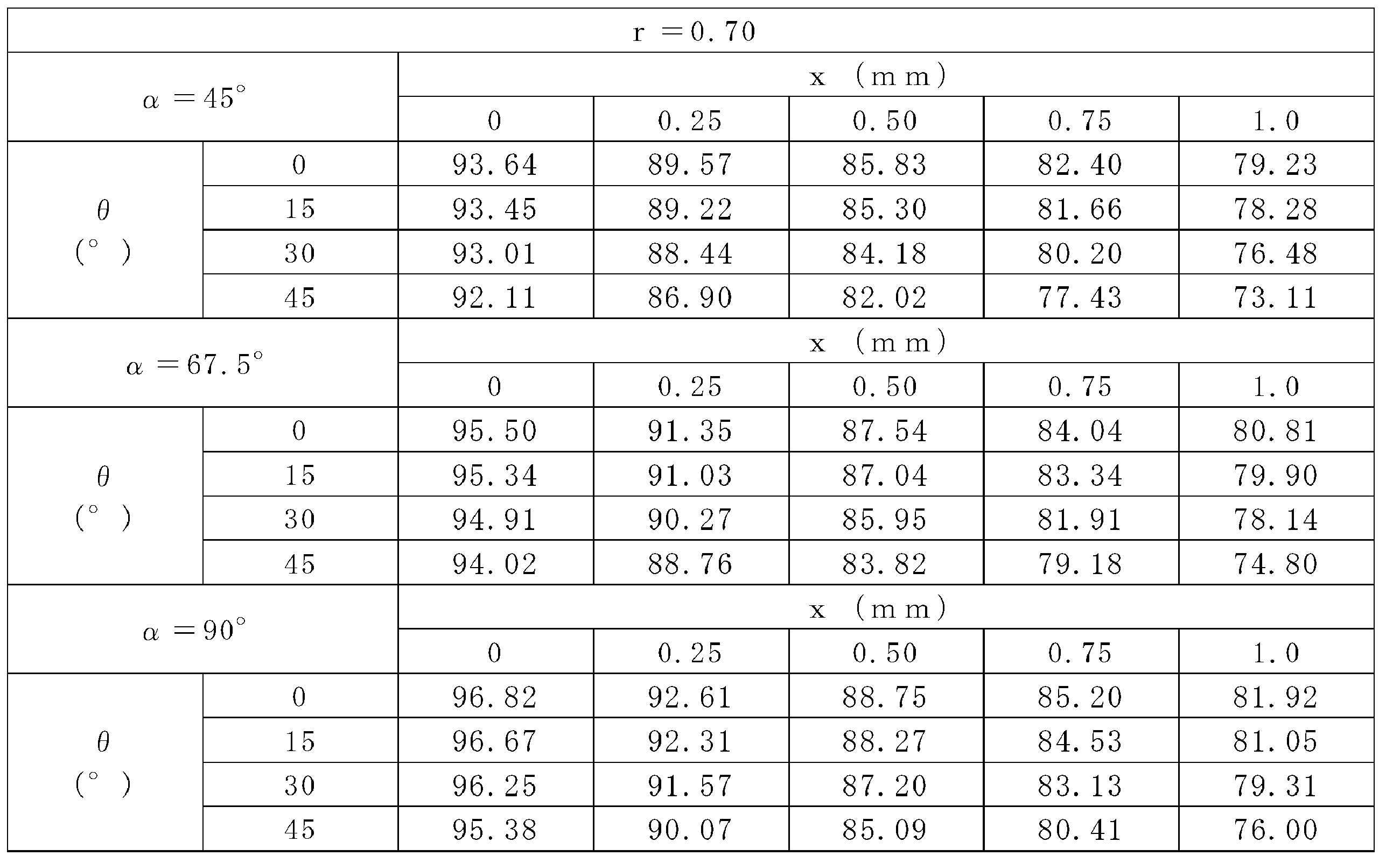
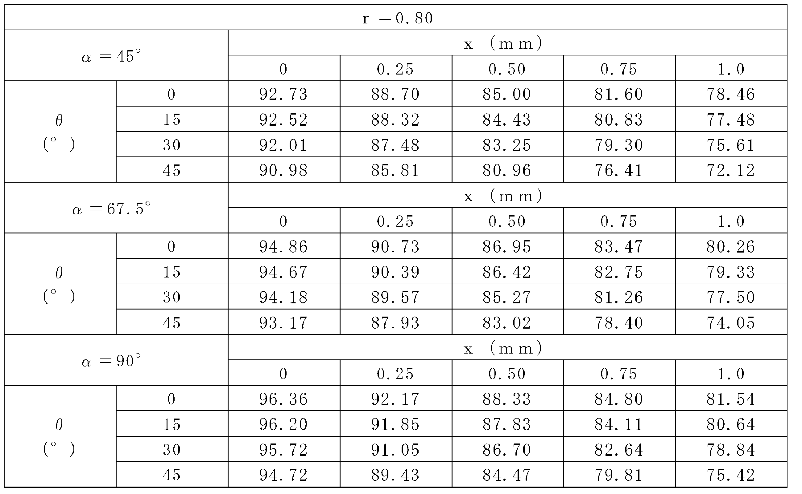

表2~表5に示す通り、本発明の第一実施形態により、ランナーの長手方向に垂直な断面上で、ランナー部6の外周に沿って、第一断熱層7又は第二断熱層8の厚さと、上記外周上における第一断熱層7及び第二断熱層8全体の最大厚さとの比を算出したとき、0°<θ≦45°及び0mm≦x≦1.0mmの範囲内で、θ、x、t、D、W、α、及びβの値を適宜選択することにより、この比が0.56~1.00となる上記外周上の部分の長さが、上記外周の長さに対して、80%以上100%未満となるように、第一金型2及び第二金型3を形成できることが確認された。
より一般的に、0°<θ≦45°、0mm≦x≦1.0mm、及び0.56≦r≦1.00の範囲内で、θ、x、r、t、D、W、α、及びβの値を適宜選択することにより、ランナー部6の外周の長さに対する長さZの割合、即ち、{-2rt/tanα+2(t+D)/cosβ+2Dtanβ+2W+2(1-r)t/(cosβcosθ-sinβsinθ)-2(t/cosβ+x)tanθ/(cosβ-sinβtanθ)}/{2x+2(t+D)/cosβ+2Dtanβ+2W+2(t/cosβ+x)/(cosθ-tanβsinθ)-2(t/cosβ+x)tanθ/(cosβ-sinβtanθ)}×100の値が80%以上100%未満となるように、第一金型2及び第二金型3を形成することができる。
特に、βがsinβ≒0、cosβ≒1、及びtanβ≒0を満たす場合、例えば、0°<β<2°を満たす場合、ランナー部6の外周の長さは、2x+2(t+D)+2W+2(t+x)/cosθ-2(t+x)tanθと近似でき、長さZは、-2rt/tanα+2(t+D)+2W+2(1-r)t/cosθ-2(t+x)tanθと近似できる。よって、この場合、0°<θ≦45°、0mm≦x≦1.0mm、及び0.56≦r≦1.00の範囲内で、θ、x、r、t、D、W、及びαの値を適宜選択することにより、ランナー部6の外周の長さに対する長さZの割合、即ち、{-2rt/tanα+2(t+D)+2W+2(1-r)t/cosθ-2(t+x)tanθ}/{2x+2(t+D)+2W+2(t+x)/cosθ-2(t+x)tanθ}×100の値が80%以上100%未満となるように、第一金型2及び第二金型3を形成することができる。
1、1A 金型
2 第一金型
3 第二金型
4 キャビティ
5 ゲート
6 ランナー部
7 第一断熱層
8 第二断熱層
9、9A 第二金型3の金型合わせ面
10、10A 開口部
11、11A 溝部
12 面取り部
13 交点
14 間隙
S スプルー
2 第一金型
3 第二金型
4 キャビティ
5 ゲート
6 ランナー部
7 第一断熱層
8 第二断熱層
9、9A 第二金型3の金型合わせ面
10、10A 開口部
11、11A 溝部
12 面取り部
13 交点
14 間隙
S スプルー
Claims (5)
- 第一金型と、前記第一金型に対向して配置される第二金型とを備え、
前記第一金型と前記第二金型との間に、成形品の形状を形成するためのキャビティと、ランナーを形成するためのランナー部とを有する金型であって、
前記第一金型及び前記第二金型において前記ランナー部を形成する金型内表面には、断熱層が設けられ、
ランナーの長手方向に垂直な断面上で、前記ランナー部の外周に沿って、前記断熱層の厚さと、前記外周上における前記断熱層の最大厚さとの比を算出したとき、前記比が0.56~1.00となる前記外周上の部分の長さが、前記外周の長さに対して、80%以上100%未満であり、
前記第一金型に形成された前記断熱層と前記第二金型に形成された前記断熱層とは、互いに接触しないように配置される金型。 - 前記ランナー部の少なくとも一部は、前記第一金型又は前記第二金型に設けられ、前記第一金型と前記第二金型との金型合わせ面に開口部を有する溝部と、前記溝部の表面に設けられた前記断熱層とから形成され、
ただし、前記開口部に隣接して、前記断熱層又は前記断熱層及び前記溝部が傾斜面により面取りされた面取り部が形成され、
前記傾斜面と前記金型合わせ面とのなす外角θが0°<θ≦45°を満たし、
ランナーの長手方向に垂直な断面上で、前記面取り部が形成されていない場合に前記溝部の表面と前記金型合わせ面とが交わる点から、前記傾斜面と前記金型合わせ面とが交わる点までの距離xが0mm≦x≦1.0mmを満たす請求項1に記載の金型。 - 前記ランナー部の少なくとも一部は、前記第一金型又は前記第二金型に設けられ、前記第一金型と前記第二金型との金型合わせ面に開口部を有する溝部と、前記溝部の表面に設けられた前記断熱層とから形成され、
ただし、前記溝部の表面に設けられた前記断熱層と前記金型合わせ面の延長面との間には、断熱層が存在しない間隙が形成されている請求項1に記載の金型。 - 請求項2に記載の金型の製造方法であって、
断熱層が形成されておらず、かつ、前記面取り部が形成されていない前記溝部の表面に断熱層を形成する断熱層形成工程と、
前記断熱層又は前記断熱層及び前記溝部を研削して、前記面取り部を形成する面取り部形成工程と、を含む金型の製造方法。 - 請求項3に記載の金型の製造方法であって、
断熱層が形成されていない前記溝部の表面に断熱層を形成する断熱層形成工程と、
前記断熱層を研削して、前記間隙を形成する間隙形成工程と、を含む金型の製造方法。
Priority Applications (1)
| Application Number | Priority Date | Filing Date | Title |
|---|---|---|---|
| JP2015517107A JP6359009B2 (ja) | 2013-05-15 | 2014-05-14 | 金型、及び金型の製造方法 |
Applications Claiming Priority (2)
| Application Number | Priority Date | Filing Date | Title |
|---|---|---|---|
| JP2013103434 | 2013-05-15 | ||
| JP2013-103434 | 2013-05-15 |
Publications (1)
| Publication Number | Publication Date |
|---|---|
| WO2014185448A1 true WO2014185448A1 (ja) | 2014-11-20 |
Family
ID=51898424
Family Applications (1)
| Application Number | Title | Priority Date | Filing Date |
|---|---|---|---|
| PCT/JP2014/062816 Ceased WO2014185448A1 (ja) | 2013-05-15 | 2014-05-14 | 金型、及び金型の製造方法 |
Country Status (3)
| Country | Link |
|---|---|
| JP (1) | JP6359009B2 (ja) |
| TW (1) | TW201515813A (ja) |
| WO (1) | WO2014185448A1 (ja) |
Cited By (1)
| Publication number | Priority date | Publication date | Assignee | Title |
|---|---|---|---|---|
| CN107377977A (zh) * | 2017-07-18 | 2017-11-24 | 东莞华晶粉末冶金有限公司 | 一种mim工艺制作手机卡托的方法和设备 |
Families Citing this family (1)
| Publication number | Priority date | Publication date | Assignee | Title |
|---|---|---|---|---|
| JP2882913B2 (ja) | 1991-06-20 | 1999-04-19 | 三菱重工業株式会社 | 4サイクルエンジン |
Citations (5)
| Publication number | Priority date | Publication date | Assignee | Title |
|---|---|---|---|---|
| JPH09123222A (ja) * | 1995-10-27 | 1997-05-13 | Sekisui Chem Co Ltd | ホットランナ金型 |
| JP2002103382A (ja) * | 2000-10-04 | 2002-04-09 | Sekisui Chem Co Ltd | 射出成形金型用ホットランナの断熱構造 |
| JP2009090558A (ja) * | 2007-10-09 | 2009-04-30 | Toshiba Corp | 射出成形金型、射出成形品の製造方法、および射出成形品 |
| JP2012187842A (ja) * | 2011-03-11 | 2012-10-04 | Nissan Motor Co Ltd | 射出成形用金型装置 |
| JP2012187841A (ja) * | 2011-03-11 | 2012-10-04 | Nissan Motor Co Ltd | 射出成形用金型装置 |
-
2014
- 2014-05-14 JP JP2015517107A patent/JP6359009B2/ja not_active Expired - Fee Related
- 2014-05-14 WO PCT/JP2014/062816 patent/WO2014185448A1/ja not_active Ceased
- 2014-05-15 TW TW103117096A patent/TW201515813A/zh unknown
Patent Citations (5)
| Publication number | Priority date | Publication date | Assignee | Title |
|---|---|---|---|---|
| JPH09123222A (ja) * | 1995-10-27 | 1997-05-13 | Sekisui Chem Co Ltd | ホットランナ金型 |
| JP2002103382A (ja) * | 2000-10-04 | 2002-04-09 | Sekisui Chem Co Ltd | 射出成形金型用ホットランナの断熱構造 |
| JP2009090558A (ja) * | 2007-10-09 | 2009-04-30 | Toshiba Corp | 射出成形金型、射出成形品の製造方法、および射出成形品 |
| JP2012187842A (ja) * | 2011-03-11 | 2012-10-04 | Nissan Motor Co Ltd | 射出成形用金型装置 |
| JP2012187841A (ja) * | 2011-03-11 | 2012-10-04 | Nissan Motor Co Ltd | 射出成形用金型装置 |
Cited By (1)
| Publication number | Priority date | Publication date | Assignee | Title |
|---|---|---|---|---|
| CN107377977A (zh) * | 2017-07-18 | 2017-11-24 | 东莞华晶粉末冶金有限公司 | 一种mim工艺制作手机卡托的方法和设备 |
Also Published As
| Publication number | Publication date |
|---|---|
| TW201515813A (zh) | 2015-05-01 |
| JPWO2014185448A1 (ja) | 2017-02-23 |
| JP6359009B2 (ja) | 2018-07-18 |
Similar Documents
| Publication | Publication Date | Title |
|---|---|---|
| JP6359009B2 (ja) | 金型、及び金型の製造方法 | |
| JP5812631B2 (ja) | 射出成形品の製造方法 | |
| JP5730868B2 (ja) | 金型の製造方法 | |
| JP5519868B2 (ja) | 金型、及び金型の製造方法 | |
| WO2013035443A1 (ja) | 樹脂複合成形体の製造方法、及び樹脂複合成形体 | |
| JP5519869B2 (ja) | 金型 | |
| JP5893454B2 (ja) | インサート部材を一体化した合成樹脂成型品及びその製造方法 | |
| CN105584007A (zh) | 一种隔热浇口套 | |
| CN106363138B (zh) | 一种用于铸件导杆孔成型的冷却部件结构 | |
| JP6085450B2 (ja) | 入れ子の製造方法 | |
| JP2014162145A (ja) | 断熱金型、及び成形品の製造方法 | |
| JP2013086465A (ja) | 射出成形用金型 | |
| CN105058561B (zh) | 一种耐磨孔砖芯子 | |
| WO2013054592A1 (ja) | 金型、及び樹脂成形体の製造方法 |
Legal Events
| Date | Code | Title | Description |
|---|---|---|---|
| 121 | Ep: the epo has been informed by wipo that ep was designated in this application |
Ref document number: 14797302 Country of ref document: EP Kind code of ref document: A1 |
|
| ENP | Entry into the national phase |
Ref document number: 2015517107 Country of ref document: JP Kind code of ref document: A |
|
| NENP | Non-entry into the national phase |
Ref country code: DE |
|
| 122 | Ep: pct application non-entry in european phase |
Ref document number: 14797302 Country of ref document: EP Kind code of ref document: A1 |