WO2014185095A1 - 非接触電力伝送用の給電装置および受電装置 - Google Patents
非接触電力伝送用の給電装置および受電装置 Download PDFInfo
- Publication number
- WO2014185095A1 WO2014185095A1 PCT/JP2014/051955 JP2014051955W WO2014185095A1 WO 2014185095 A1 WO2014185095 A1 WO 2014185095A1 JP 2014051955 W JP2014051955 W JP 2014051955W WO 2014185095 A1 WO2014185095 A1 WO 2014185095A1
- Authority
- WO
- WIPO (PCT)
- Prior art keywords
- cover
- temperature
- sensing means
- temperature sensing
- power
- Prior art date
- Legal status (The legal status is an assumption and is not a legal conclusion. Google has not performed a legal analysis and makes no representation as to the accuracy of the status listed.)
- Ceased
Links
Images


Classifications
-
- H—ELECTRICITY
- H02—GENERATION; CONVERSION OR DISTRIBUTION OF ELECTRIC POWER
- H02J—ELECTRIC POWER NETWORKS; CIRCUIT ARRANGEMENTS OR SYSTEMS FOR SUPPLYING OR DISTRIBUTING ELECTRIC POWER; SYSTEMS FOR STORING ELECTRIC ENERGY
- H02J50/00—Circuit arrangements or systems for wireless supply or distribution of electric power
- H02J50/10—Circuit arrangements or systems for wireless supply or distribution of electric power using inductive coupling
-
- G—PHYSICS
- G01—MEASURING; TESTING
- G01K—MEASURING TEMPERATURE; MEASURING QUANTITY OF HEAT; THERMALLY-SENSITIVE ELEMENTS NOT OTHERWISE PROVIDED FOR
- G01K1/00—Details of thermometers not specially adapted for particular types of thermometer
- G01K1/02—Means for indicating or recording specially adapted for thermometers
- G01K1/026—Means for indicating or recording specially adapted for thermometers arrangements for monitoring a plurality of temperatures, e.g. by multiplexing
-
- G—PHYSICS
- G01—MEASURING; TESTING
- G01K—MEASURING TEMPERATURE; MEASURING QUANTITY OF HEAT; THERMALLY-SENSITIVE ELEMENTS NOT OTHERWISE PROVIDED FOR
- G01K13/00—Thermometers specially adapted for specific purposes
-
- G—PHYSICS
- G01—MEASURING; TESTING
- G01K—MEASURING TEMPERATURE; MEASURING QUANTITY OF HEAT; THERMALLY-SENSITIVE ELEMENTS NOT OTHERWISE PROVIDED FOR
- G01K7/00—Measuring temperature based on the use of electric or magnetic elements directly sensitive to heat ; Power supply therefor, e.g. using thermoelectric elements
- G01K7/16—Measuring temperature based on the use of electric or magnetic elements directly sensitive to heat ; Power supply therefor, e.g. using thermoelectric elements using resistive elements
- G01K7/22—Measuring temperature based on the use of electric or magnetic elements directly sensitive to heat ; Power supply therefor, e.g. using thermoelectric elements using resistive elements the element being a non-linear resistance, e.g. thermistor
-
- H—ELECTRICITY
- H02—GENERATION; CONVERSION OR DISTRIBUTION OF ELECTRIC POWER
- H02J—ELECTRIC POWER NETWORKS; CIRCUIT ARRANGEMENTS OR SYSTEMS FOR SUPPLYING OR DISTRIBUTING ELECTRIC POWER; SYSTEMS FOR STORING ELECTRIC ENERGY
- H02J50/00—Circuit arrangements or systems for wireless supply or distribution of electric power
- H02J50/005—Mechanical details of housing or structure aiming to accommodate the power transfer means, e.g. mechanical integration of coils, antennas or transducers into emitting or receiving devices
-
- H—ELECTRICITY
- H02—GENERATION; CONVERSION OR DISTRIBUTION OF ELECTRIC POWER
- H02J—ELECTRIC POWER NETWORKS; CIRCUIT ARRANGEMENTS OR SYSTEMS FOR SUPPLYING OR DISTRIBUTING ELECTRIC POWER; SYSTEMS FOR STORING ELECTRIC ENERGY
- H02J50/00—Circuit arrangements or systems for wireless supply or distribution of electric power
- H02J50/10—Circuit arrangements or systems for wireless supply or distribution of electric power using inductive coupling
- H02J50/12—Circuit arrangements or systems for wireless supply or distribution of electric power using inductive coupling of the resonant type
-
- H—ELECTRICITY
- H02—GENERATION; CONVERSION OR DISTRIBUTION OF ELECTRIC POWER
- H02J—ELECTRIC POWER NETWORKS; CIRCUIT ARRANGEMENTS OR SYSTEMS FOR SUPPLYING OR DISTRIBUTING ELECTRIC POWER; SYSTEMS FOR STORING ELECTRIC ENERGY
- H02J7/00—Circuit arrangements for charging or discharging batteries or for supplying loads from batteries
- H02J7/34—Parallel operation in networks using both storage and other DC sources, e.g. providing buffering
- H02J7/35—Parallel operation in networks using both storage and other DC sources, e.g. providing buffering with light sensitive cells
-
- H—ELECTRICITY
- H02—GENERATION; CONVERSION OR DISTRIBUTION OF ELECTRIC POWER
- H02J—ELECTRIC POWER NETWORKS; CIRCUIT ARRANGEMENTS OR SYSTEMS FOR SUPPLYING OR DISTRIBUTING ELECTRIC POWER; SYSTEMS FOR STORING ELECTRIC ENERGY
- H02J50/00—Circuit arrangements or systems for wireless supply or distribution of electric power
- H02J50/60—Circuit arrangements or systems for wireless supply or distribution of electric power responsive to the presence of foreign objects, e.g. detection of living beings
Definitions
- the present invention relates to a power feeding device and a power receiving device that transmit power to a device in a contactless manner.
- the power supply device includes a primary coil that generates magnetic flux when an alternating current flows, a cover that covers the primary coil, and a sheet-like temperature sensor that detects the temperature of an object (foreign matter or power receiving device) on the cover. Yes.
- a temperature sensor is used during power transmission to detect the temperature rise on the cover and to detect the presence of an object on the cover.
- the coil is a support base that passes an electromagnetic field and is disposed on a support base made of an insulating material, and the cover is attached to the support base so as to cover the coil.
- the temperature sensor is disposed above the coil and inside the cover.
- the temperature sensor can be arranged on the top surface of the cover or inside the cover (that is, between the top surface and the back surface).
- the power receiving device can also be provided with a temperature sensor.
- the power feeding device has a problem that the temperature of the object may not be detected accurately when the object is placed on the cover depending on the position of the temperature sensor.
- an object of the present invention is to provide a power feeding device and a power receiving device that can accurately detect the temperature of an object on a cover.
- one aspect of the present invention is a power feeding device and a power receiving device that transmit power to a power receiving device in a contactless manner, the cover being covered by the cover, and in a predetermined direction with respect to the cover.
- a coil provided; and temperature sensing means for detecting an object temperature on the cover.
- the distance along the predetermined direction from the cover surface to the temperature sensing means is L [m]
- the temperature of the object to be temperature-detected by the temperature sensing means is T 0 [K]
- the temperature to be detected by the temperature sensing means is Is T 1 [K]
- the thermal conductivity of the cover is ⁇ [W / (m ⁇ K)]
- L satisfies the following formula (1).
- the temperature of the object on the cover can be accurately detected by designing the distance L from the cover surface to the temperature sensing means to be a numerical value defined by the above equation (1). .
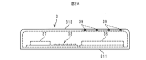
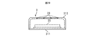
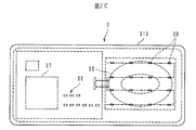
- FIG. 2A It is a block diagram which shows the structure of the non-contact electric power transmission system provided with the electric power feeder which concerns on one Embodiment of this invention, and an electric power receiving apparatus. It is a side view of the electric power feeder shown in FIG. It is a front view of the electric power feeder shown in FIG. It is a top view of the electric power feeder shown in FIG. It is a figure which shows the parameter relevant to the distance from the surface shown to FIG. 2A to a temperature sensing means.
- the non-contact power transmission system 1 includes a power feeding device 3.
- the power feeding device 3 is roughly configured by an adapter 31, a transmission system component group 33, a primary coil 35, a primary side controller 37, and a temperature sensing means 39.
- the component group 33, the coil 35, and the controller 37 are arranged on the base 311 and covered with a cover 313 as indicated by dotted lines in FIG. 2A and FIG. 2B.
- the power receiving device 5 includes a secondary coil 51, a transmission system component group 53, and a secondary controller 55.
- the adapter 31 supplies an AC voltage (for example, 100 V) from a commercial power source to the transmission system component group 33.
- the transmission system component group 33 constitutes a rectifier circuit, a smoothing circuit, an inverter circuit, and the like.
- the rectifier circuit and the smoothing circuit convert the input AC voltage into a DC voltage.
- the inverter circuit generates an AC voltage having a predetermined frequency (for example, several tens of kHz) by switching the output DC voltage of the smoothing circuit.
- a predetermined frequency for example, several tens of kHz
- the power receiving device 5 is placed on the cover 313 of the power feeding device 3 so that the secondary coil 51 is positioned on the primary coil 35 with the cover 313 interposed therebetween. Therefore, the alternating magnetic field generated in the coil 35 is linked to the coil 51, and an alternating voltage is induced at both ends of the coil 51 and supplied to the transmission system component group 53.
- the transmission system component group 53 includes a rectifier circuit and the like, rectifies the current flowing by the induced voltage, and supplies the rectified circuit to the battery 57 disposed outside the power receiving device 5. Thereby, the battery 57 is charged. The above operation is controlled by the controller 55.
- the power feeding device 3 includes a temperature sensing means 39.
- a typical example of the temperature sensing means 39 is a ceramic thermistor (hereinafter referred to as an NTC thermistor) having a negative temperature coefficient.
- the temperature sensing means 39 is preferably a small NTC thermistor (for example, 1005 type described in JIS standard) having a small heat capacity.
- the dimension in the Y-axis direction is 1.0 mm
- the dimension in the X-axis direction is 0.5 mm.
- the dimension in the Z-axis direction is not defined by the JIS standard, but is, for example, 0.25 mm.
- thermosenor means 39 is provided between the surface of the cover 313 and the upper end of the primary coil 35.
- 2A to 2C show an example in which the temperature sensing means 39 is embedded in the cover 313.
- a plurality of temperature sensing means 39 that is, a plurality of NTC thermistors are connected in a daisy chain as shown by the dotted line in FIG. 2C. It is preferable to embed each of 39 in different positions in the cover 313. As a result, the temperature at a plurality of locations on the cover 313 can be detected.
- the temperature sensing means 39 includes a fixed resistor (not shown) connected in series. A constant voltage generated by a constant voltage circuit (not shown) is supplied to such a circuit. This circuit outputs the divided potential with the fixed resistor to the controller 37 as temperature information. The controller 37 stops the power supply to the primary coil 35 when the input temperature information exceeds the predetermined temperature.
- the primary coil 35 generates heat due to power supply. That is, even if the power receiving device 5 and the metal foreign object are not present on the cover 313, the cover 313 becomes high temperature. Therefore, if the temperature sensing means 39 is not provided at an appropriate distance from the surface of the cover 313 (in other words, the mounting surface of the power receiving device 5), the controller 37 accurately detects the temperature of the object on the cover 313. It may not be possible. If the distance from the surface of the cover 313 to the temperature sensing means 39 is too far, the temperature of the object of the controller 37 cannot be accurately detected.
- the present inventor has found an expression for deriving a distance L along the vertical direction from the surface of the cover 313 to the temperature sensing means 39.
- the temperature of the object placed on the surface of the cover 313 is T 0 [K]
- the temperature of the object to be detected by the controller 37 is T 1 [K] (where T 1 ⁇ T 0 ).
- the thermal conductivity of the cover 313 is ⁇ [W / (m ⁇ K)].
- the distance L [m] is designed to be a numerical value satisfying the following expression (1). That is, the temperature sensing means 39 is provided at a position separated from the surface of the cover 313 by a distance L [m].
- the object to be detected is a 5 [cm] square aluminum piece.
- the cover 313 is made of an epoxy resin having a thermal conductivity ⁇ of 0.25 [W / (m ⁇ K)].
- the temperature sensing means 39 may detect the presence of an aluminum piece at a temperature T 1 of 130 ° C. (temperature difference (T 0 -T 1 ) is 20 ° C.), for example. desirable.
- the power feeding device 3 is designed so that the distance L is 0.00248 [m] or less.
- T 0 and T 1 are substituted with absolute temperatures. However, from the viewpoint of easy understanding in texts and tables, T 0 and T 1 are not expressed in absolute temperatures but in degrees Celsius. Has been.
- the present inventor actually has a circuit in which a 1005 type NTC thermistor as a temperature sensing means 39 is embedded in an epoxy resin cover 313 at six distances L shown in Table 1 below (in Table 1, evaluation sample No. .. No. 1 to No. 6) were prepared. Sample No. 1 and the distance L is 50 [mm]. The distance L of 2 was 20 [mm]. Sample No. 3 to No. 6 is as described in Table 1.
- the inventor placed an aluminum piece to be detected on the cover 313 of each sample, and measured the temperature T 1 from the resistance value of the temperature sensing means 39 that became saturated in the sample.
- Parameters T 0 and ⁇ other than the distance L and temperature T 1 are as described above.
- the measurement results are as shown in Table 1.
- the temperature T 1 was less than 130 ° C., and the temperature difference (T 0 ⁇ T 1 ) was more than 20 ° C.
- the distance L does not satisfy Expression (1)
- sample no. 5 and no. 6 the temperature T 1 was 130 ° C. or more, and the temperature difference (T 0 ⁇ T 1 ) was 20 ° C. or less.
- the distance L satisfies the formula (1), it can be seen that the temperature of the object on the cover 313 can be accurately detected as designed.
- T 0 150 [° C.]. If the temperature T 1 is set to 130 [° C.] (the temperature difference (T 0 ⁇ T 1 ) is 20 ° C.), the distance L is 0.00169 [m] or less from the previous equation (1).
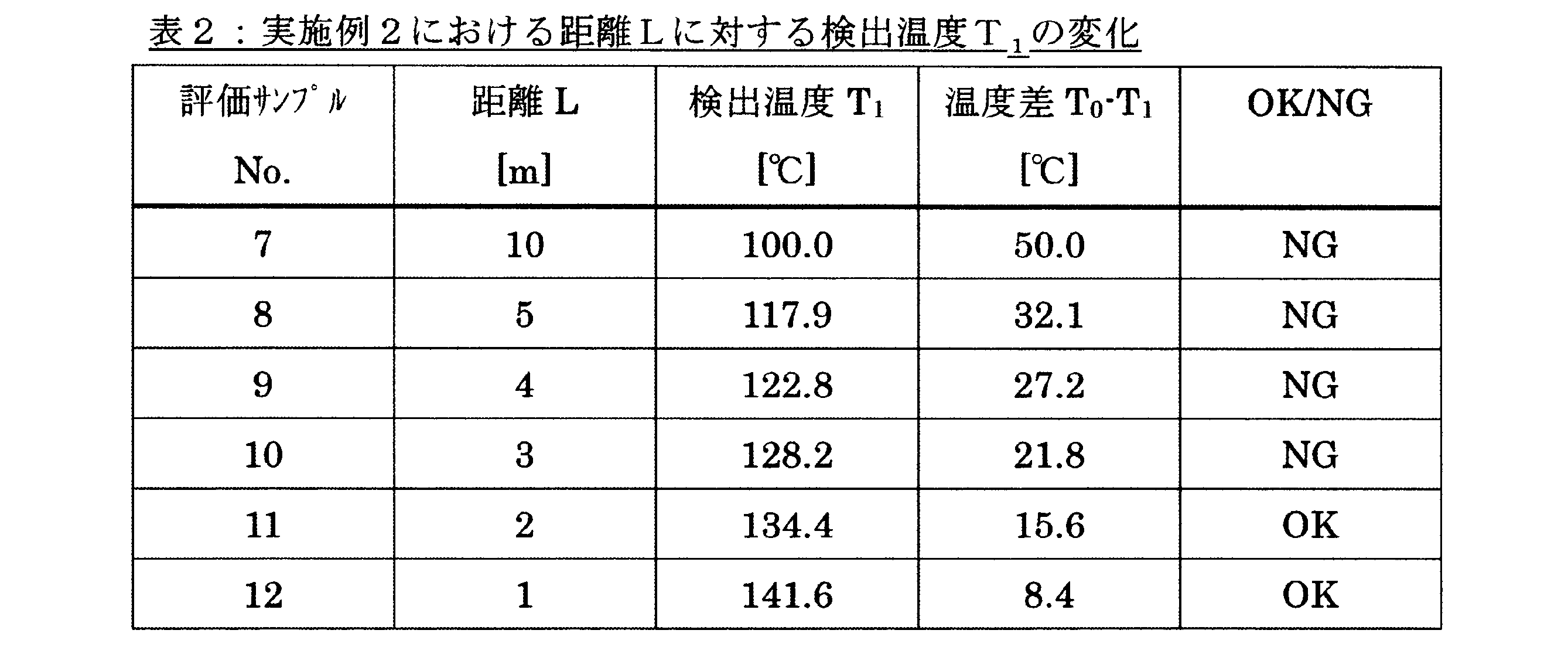
- the inventor made a circuit in which a 1005 type NTC thermistor as a temperature sensing means 39 was embedded in a glass cover 313 at six distances L shown in Table 2 below (in Table 2, evaluation samples No. 7 to No. 7). 12) is prepared. Sample No. 7, the distance L is 10 [mm]. The distance L of 8 was 5 [mm]. Sample No. 9-No. 12 is as described in Table 2.
- the inventor measured the temperature T 1 in the same manner as in the first example.
- the measurement results are as shown in Table 2.
- Sample No. 7-No. 10 the temperature T 1 was less than 130 [° C.].
- the temperature of the object on the cover 313 could not be accurately detected unless the distance L satisfies the formula (1).
- sample no. 11 and no. 12 the temperature T 1 is 130 ° C. or higher, and even in the second embodiment, when the distance L satisfies Equation (1), the temperature of the object on the cover 313 can be accurately detected as designed. It was. In other words, it has been found that the second embodiment has the same effect as the first embodiment.
- the power supply device 3 has been described for charging purposes such as smartphones and tablet terminals.
- the present invention is not limited to this, and the power feeding device 3 may be used for charging an electric vehicle or a consumer device such as a shaver.
- the temperature sensing means 39 has been described as an NTC thermistor.
- the present invention is not limited to this, and a PTC thermistor having a positive temperature coefficient may be used.
- the thermistor is not limited to a ceramic thermistor, and may be a thermistor made of a polymer material.
- the NTC thermistor is not limited to the 1005 type, and may be a 3225 type, 3216 type, 2012 type, 1608 type, 0603 type, or 0402 type. Regarding these, dimensions in the X-axis, Y-axis, and Z-axis directions are as shown in Table 3 below.
- the power feeding device and the power receiving device according to the present invention can accurately detect overheating of an object on the cover, and are suitable for a non-contact charging system such as a smartphone, a tablet terminal, or an electric vehicle.
Landscapes
- Engineering & Computer Science (AREA)
- Power Engineering (AREA)
- Physics & Mathematics (AREA)
- General Physics & Mathematics (AREA)
- Computer Networks & Wireless Communication (AREA)
- Nonlinear Science (AREA)
- Charge And Discharge Circuits For Batteries Or The Like (AREA)
- Measuring Temperature Or Quantity Of Heat (AREA)
Abstract
Description

以下、図面を参照して、本発明の一実施形態に係る給電装置について説明する。
図1において、非接触電力伝送システム1は、給電装置3を備えている。給電装置3は、スマートフォンやタブレット端末等の受電装置5を充電するために、大略的に、アダプタ31と、伝送系部品群33と、一次コイル35と、一次側コントローラ37と、感温手段39と、を含んでいる。ここで、部品群33、コイル35およびコントローラ37は、図2Aや図2Bに点線で示すように、ベース311に配置され、カバー313により覆われる。それに対し、受電装置5は、図1に示すように、二次コイル51と、伝送系部品群53と、二次側コントローラ55と、を含んでいる。以下、各構成の詳細や動作について説明する。
ところで、カバー313上には、受電装置5が載置されるだけでなく、金属異物が載ってしまうことがある。これら物体(受電装置5や金属異物)の異常発熱を検知するために、給電装置3には、感温手段39が備わっている。

検出対象となる物体は5[cm]四方のアルミ片とする。また、カバー313の材質を、熱伝導率λが0.25[W/(m・K)]のエポキシ樹脂とする。このカバー313上に上記アルミ片を置くと、25[℃]で無風の条件では、このアルミ片の温度T0は150[℃]まで上昇した。給電装置3の安全性等を考慮した場合、例えば130[℃]の温度T1(温度差(T0-T1)は20℃)で感温手段39がアルミ片の存在を検出することが望ましい。この場合、距離Lが0.00248[m]以下となるよう、給電装置3は設計される。なお、式(1)においてT0,T1は絶対温度で代入されるが、文章中や表中では分かり易さの観点から、T0,T1は、絶対温度ではなく、セルシウス度で記載されている。

以上のように、給電装置3における、カバー313の表面から感温手段39までの距離Lを式(1)に基づき設計すると、設計目標と概ね合致するように的確にカバー313上の物体の温度を検出できる。したがって、λ、T1、T0という設計条件が与えられれば、感温手段39を埋め込んだカバー313の試作および評価を繰り返すことなく、適切な距離Lを求めることが可能となる。これにより、給電装置3の設計効率が向上する。
発明者はさらに、カバー313の材質を、エポキシ樹脂に代えて、熱伝導率λが0.17[W/(m・K)]のガラスで作製した。この場合も、上記同様に、5[cm]四方のアルミ片を検出対象とすると、T0は150[℃]となる。また、温度T1を130[℃](温度差(T0-T1)は20℃)と設定すると、距離Lは前式(1)から0.00169[m]以下となる。
上記実施形態では、給電装置3のカバー313に感温手段39を設ける場合における距離Lについて説明した。しかし、これに限らず、受電装置5側のカバーから感温手段39までの距離Lを数(1)に基づき定めても構わない。

3 給電装置
35 一次コイル
39 感温手段
313カバー
5 受電装置
Claims (4)
- 受電装置に非接触で電力を供給する給電装置であって、
カバーと、
前記カバーによって覆われ、前記カバーに対し所定方向に設けられたコイルと、
前記カバー上の物体温度を検出する感温手段と、を備え、
前記カバー表面から前記感温手段までの前記所定方向に沿う距離をL[m]、前記感温手段による検温対象となる物体の温度をT0[K]、前記感温手段により検出すべき温度をT1[K]、前記カバーの熱伝導率をλ[W/(m・K)]、とすると、
Lは、

- 前記感温手段は、複数のサーミスタを数珠つなぎにしたものである、請求項1に記載の給電装置。
- 前記感温手段は、1005型のサーミスタである、請求項1または2に記載の給電装置。
- 給電装置から非接触で伝送されてくる電力を受電する受電装置であって、
カバーと、
前記カバーによって覆われ、前記カバーに対し所定方向に設けられたコイルと、
前記カバー上の物体温度を検出する感温手段と、を備え、
前記カバー表面から前記感温手段までの前記所定方向に沿う距離をL[m]、前記感温手段による検温対象となる物体の温度をT0[K]、前記感温手段により検出すべき温度をT1[K]、前記カバーの熱伝導率をλ[W/(m・K)]、とすると、
Lは、

Priority Applications (3)
| Application Number | Priority Date | Filing Date | Title |
|---|---|---|---|
| CN201480028103.7A CN105264347B (zh) | 2013-05-14 | 2014-01-29 | 用于非接触电力传输的供电装置及受电装置 |
| JP2015516948A JP6090439B2 (ja) | 2013-05-14 | 2014-01-29 | 非接触電力伝送用の給電装置および受電装置 |
| US14/937,966 US9887559B2 (en) | 2013-05-14 | 2015-11-11 | Power feeding device and power receiving device for contactless power transmission |
Applications Claiming Priority (2)
| Application Number | Priority Date | Filing Date | Title |
|---|---|---|---|
| JP2013101969 | 2013-05-14 | ||
| JP2013-101969 | 2013-05-14 |
Related Child Applications (1)
| Application Number | Title | Priority Date | Filing Date |
|---|---|---|---|
| US14/937,966 Continuation US9887559B2 (en) | 2013-05-14 | 2015-11-11 | Power feeding device and power receiving device for contactless power transmission |
Publications (1)
| Publication Number | Publication Date |
|---|---|
| WO2014185095A1 true WO2014185095A1 (ja) | 2014-11-20 |
Family
ID=51898083
Family Applications (1)
| Application Number | Title | Priority Date | Filing Date |
|---|---|---|---|
| PCT/JP2014/051955 Ceased WO2014185095A1 (ja) | 2013-05-14 | 2014-01-29 | 非接触電力伝送用の給電装置および受電装置 |
Country Status (4)
| Country | Link |
|---|---|
| US (1) | US9887559B2 (ja) |
| JP (1) | JP6090439B2 (ja) |
| CN (1) | CN105264347B (ja) |
| WO (1) | WO2014185095A1 (ja) |
Families Citing this family (4)
| Publication number | Priority date | Publication date | Assignee | Title |
|---|---|---|---|---|
| CN104995817B (zh) * | 2013-02-14 | 2017-10-20 | 丰田自动车株式会社 | 受电装置和送电装置 |
| US10326316B2 (en) * | 2017-02-10 | 2019-06-18 | Apple Inc. | Wireless charging system with inductance imaging |
| US10658878B2 (en) | 2018-08-31 | 2020-05-19 | Apple Inc. | Wireless charging system with temperature sensor array |
| US10505403B1 (en) | 2018-08-31 | 2019-12-10 | Apple Inc. | Wireless charging system with temperature sensing |
Citations (5)
| Publication number | Priority date | Publication date | Assignee | Title |
|---|---|---|---|---|
| JP2009264803A (ja) * | 2008-04-23 | 2009-11-12 | Murata Mfg Co Ltd | 面状温度検出センサ |
| WO2012047779A1 (en) * | 2010-10-06 | 2012-04-12 | Witricity Corporation | Vehicle charger safety system and method |
| JP2012228123A (ja) * | 2011-04-21 | 2012-11-15 | Nissan Motor Co Ltd | 非接触給電装置 |
| JP2013005682A (ja) * | 2011-06-21 | 2013-01-07 | Panasonic Corp | 非接触電力伝送システム |
| JP2013030551A (ja) * | 2011-07-27 | 2013-02-07 | Panasonic Corp | 非接触給電装置 |
Family Cites Families (11)
| Publication number | Priority date | Publication date | Assignee | Title |
|---|---|---|---|---|
| JP3471207B2 (ja) | 1997-12-09 | 2003-12-02 | 株式会社デンソー | 電気自動車用組み電池の異常高温検出装置 |
| JP2008017562A (ja) | 2006-07-03 | 2008-01-24 | Mitsubishi Electric Corp | 非接触充電器 |
| JP5049018B2 (ja) * | 2007-01-09 | 2012-10-17 | ソニーモバイルコミュニケーションズ株式会社 | 非接触充電装置 |
| KR100819753B1 (ko) * | 2007-07-13 | 2008-04-08 | 주식회사 한림포스텍 | 배터리팩 솔루션을 위한 무접점충전시스템 및 그 제어방법 |
| JP5432283B2 (ja) * | 2008-12-12 | 2014-03-05 | ハンリム ポステック カンパニー リミテッド | 無接点電力受信装置及び受信装置用コアを製作するためのジグ |
| JP2010252538A (ja) | 2009-04-16 | 2010-11-04 | Mitsumi Electric Co Ltd | 電池保護モジュールおよびリードサーミスタ取付け方法 |
| JP5394135B2 (ja) | 2009-06-15 | 2014-01-22 | 三洋電機株式会社 | 充電台 |
| JP2011222773A (ja) | 2010-04-09 | 2011-11-04 | Sony Chemical & Information Device Corp | ポリマー温度ヒューズ素子、温度センサー、バッテリパック |
| JP2013017247A (ja) * | 2011-06-30 | 2013-01-24 | Panasonic Corp | 非接触電力伝送に用いられる給電装置及び受電装置 |
| WO2014063159A2 (en) * | 2012-10-19 | 2014-04-24 | Witricity Corporation | Foreign object detection in wireless energy transfer systems |
| WO2014185096A1 (ja) * | 2013-05-14 | 2014-11-20 | 株式会社村田製作所 | 非接触電力伝送用の給電装置および受電装置 |
-
2014
- 2014-01-29 JP JP2015516948A patent/JP6090439B2/ja active Active
- 2014-01-29 WO PCT/JP2014/051955 patent/WO2014185095A1/ja not_active Ceased
- 2014-01-29 CN CN201480028103.7A patent/CN105264347B/zh active Active
-
2015
- 2015-11-11 US US14/937,966 patent/US9887559B2/en active Active
Patent Citations (5)
| Publication number | Priority date | Publication date | Assignee | Title |
|---|---|---|---|---|
| JP2009264803A (ja) * | 2008-04-23 | 2009-11-12 | Murata Mfg Co Ltd | 面状温度検出センサ |
| WO2012047779A1 (en) * | 2010-10-06 | 2012-04-12 | Witricity Corporation | Vehicle charger safety system and method |
| JP2012228123A (ja) * | 2011-04-21 | 2012-11-15 | Nissan Motor Co Ltd | 非接触給電装置 |
| JP2013005682A (ja) * | 2011-06-21 | 2013-01-07 | Panasonic Corp | 非接触電力伝送システム |
| JP2013030551A (ja) * | 2011-07-27 | 2013-02-07 | Panasonic Corp | 非接触給電装置 |
Also Published As
| Publication number | Publication date |
|---|---|
| CN105264347B (zh) | 2018-01-09 |
| JPWO2014185095A1 (ja) | 2017-02-23 |
| CN105264347A (zh) | 2016-01-20 |
| US20160064954A1 (en) | 2016-03-03 |
| JP6090439B2 (ja) | 2017-03-08 |
| US9887559B2 (en) | 2018-02-06 |
Similar Documents
| Publication | Publication Date | Title |
|---|---|---|
| JP6090172B2 (ja) | 無接点充電方法 | |
| US20130163635A1 (en) | Foreign object detection in inductive coupled wireless power transfer environment using thermal sensors | |
| CN103368277B (zh) | 电力接收装置及其控制方法以及电力输送系统 | |
| WO2011132471A1 (ja) | 非接触送電装置、非接触受電装置及び非接触充電システム | |
| CN106981889B (zh) | 功率馈送设备和功率馈送方法 | |
| CN106796303B (zh) | 用于感应充电设备的异物识别的方法以及感应充电设备 | |
| JP6424952B2 (ja) | 非接触受電装置の温度推定装置及び温度推定方法 | |
| JP6090439B2 (ja) | 非接触電力伝送用の給電装置および受電装置 | |
| CN106716180B (zh) | 用于感应充电设备的异物识别的方法以及感应充电设备 | |
| JPWO2009040998A1 (ja) | 非接触充電器 | |
| TW201212459A (en) | Non-contact electric power supply device and non-contact charging system | |
| CN104467128B (zh) | 识别用于无线能量传输的磁场中的外来物的装置和方法 | |
| WO2013145835A1 (ja) | 受電装置、電気回路、および、給電装置 | |
| CN103427496A (zh) | 电力接收设备和电力馈送系统 | |
| CN102345886A (zh) | 温度传感器和具有所述温度传感器的感应加热烹饪器 | |
| JP2014093921A (ja) | 無接点充電装置及び無接点充電方法 | |
| JP2015195633A (ja) | 非接触給電装置 | |
| JP6090440B2 (ja) | 非接触電力伝送用の給電装置および受電装置 | |
| JP2016007100A (ja) | 非接触電力伝送用の給電装置および受電装置 | |
| WO2013061611A1 (ja) | 非接触電力伝送装置 | |
| US10476318B2 (en) | Battery-embedded device | |
| WO2014185094A1 (ja) | 非接触電力伝送用の給電装置および受電装置 | |
| JP4848792B2 (ja) | 誘導加熱装置 | |
| JP2026511372A (ja) | 無線充電における温度センサ及び用途 |
Legal Events
| Date | Code | Title | Description |
|---|---|---|---|
| WWE | Wipo information: entry into national phase |
Ref document number: 201480028103.7 Country of ref document: CN |
|
| 121 | Ep: the epo has been informed by wipo that ep was designated in this application |
Ref document number: 14797933 Country of ref document: EP Kind code of ref document: A1 |
|
| ENP | Entry into the national phase |
Ref document number: 2015516948 Country of ref document: JP Kind code of ref document: A |
|
| NENP | Non-entry into the national phase |
Ref country code: DE |
|
| 122 | Ep: pct application non-entry in european phase |
Ref document number: 14797933 Country of ref document: EP Kind code of ref document: A1 |