WO2014185067A1 - Dispositif d'implantation de capteur et système d'implantation de capteur - Google Patents
Dispositif d'implantation de capteur et système d'implantation de capteur Download PDFInfo
- Publication number
- WO2014185067A1 WO2014185067A1 PCT/JP2014/002534 JP2014002534W WO2014185067A1 WO 2014185067 A1 WO2014185067 A1 WO 2014185067A1 JP 2014002534 W JP2014002534 W JP 2014002534W WO 2014185067 A1 WO2014185067 A1 WO 2014185067A1
- Authority
- WO
- WIPO (PCT)
- Prior art keywords
- sensor
- fixing portion
- opening
- bar
- needle
- Prior art date
Links
Images


Classifications
-
- A—HUMAN NECESSITIES
- A61—MEDICAL OR VETERINARY SCIENCE; HYGIENE
- A61B—DIAGNOSIS; SURGERY; IDENTIFICATION
- A61B17/00—Surgical instruments, devices or methods, e.g. tourniquets
- A61B17/34—Trocars; Puncturing needles
- A61B17/3468—Trocars; Puncturing needles for implanting or removing devices, e.g. prostheses, implants, seeds, wires
-
- A—HUMAN NECESSITIES
- A61—MEDICAL OR VETERINARY SCIENCE; HYGIENE
- A61B—DIAGNOSIS; SURGERY; IDENTIFICATION
- A61B5/00—Measuring for diagnostic purposes; Identification of persons
- A61B5/145—Measuring characteristics of blood in vivo, e.g. gas concentration, pH value; Measuring characteristics of body fluids or tissues, e.g. interstitial fluid, cerebral tissue
- A61B5/14546—Measuring characteristics of blood in vivo, e.g. gas concentration, pH value; Measuring characteristics of body fluids or tissues, e.g. interstitial fluid, cerebral tissue for measuring analytes not otherwise provided for, e.g. ions, cytochromes
-
- A—HUMAN NECESSITIES
- A61—MEDICAL OR VETERINARY SCIENCE; HYGIENE
- A61B—DIAGNOSIS; SURGERY; IDENTIFICATION
- A61B5/00—Measuring for diagnostic purposes; Identification of persons
- A61B5/145—Measuring characteristics of blood in vivo, e.g. gas concentration, pH value; Measuring characteristics of body fluids or tissues, e.g. interstitial fluid, cerebral tissue
- A61B5/1455—Measuring characteristics of blood in vivo, e.g. gas concentration, pH value; Measuring characteristics of body fluids or tissues, e.g. interstitial fluid, cerebral tissue using optical sensors, e.g. spectral photometrical oximeters
- A61B5/14551—Measuring characteristics of blood in vivo, e.g. gas concentration, pH value; Measuring characteristics of body fluids or tissues, e.g. interstitial fluid, cerebral tissue using optical sensors, e.g. spectral photometrical oximeters for measuring blood gases
- A61B5/14556—Measuring characteristics of blood in vivo, e.g. gas concentration, pH value; Measuring characteristics of body fluids or tissues, e.g. interstitial fluid, cerebral tissue using optical sensors, e.g. spectral photometrical oximeters for measuring blood gases by fluorescence
-
- A—HUMAN NECESSITIES
- A61—MEDICAL OR VETERINARY SCIENCE; HYGIENE
- A61B—DIAGNOSIS; SURGERY; IDENTIFICATION
- A61B5/00—Measuring for diagnostic purposes; Identification of persons
- A61B5/145—Measuring characteristics of blood in vivo, e.g. gas concentration, pH value; Measuring characteristics of body fluids or tissues, e.g. interstitial fluid, cerebral tissue
- A61B5/1455—Measuring characteristics of blood in vivo, e.g. gas concentration, pH value; Measuring characteristics of body fluids or tissues, e.g. interstitial fluid, cerebral tissue using optical sensors, e.g. spectral photometrical oximeters
- A61B5/1459—Measuring characteristics of blood in vivo, e.g. gas concentration, pH value; Measuring characteristics of body fluids or tissues, e.g. interstitial fluid, cerebral tissue using optical sensors, e.g. spectral photometrical oximeters invasive, e.g. introduced into the body by a catheter
-
- A—HUMAN NECESSITIES
- A61—MEDICAL OR VETERINARY SCIENCE; HYGIENE
- A61B—DIAGNOSIS; SURGERY; IDENTIFICATION
- A61B5/00—Measuring for diagnostic purposes; Identification of persons
- A61B5/68—Arrangements of detecting, measuring or recording means, e.g. sensors, in relation to patient
- A61B5/6846—Arrangements of detecting, measuring or recording means, e.g. sensors, in relation to patient specially adapted to be brought in contact with an internal body part, i.e. invasive
- A61B5/6847—Arrangements of detecting, measuring or recording means, e.g. sensors, in relation to patient specially adapted to be brought in contact with an internal body part, i.e. invasive mounted on an invasive device
- A61B5/686—Permanently implanted devices, e.g. pacemakers, other stimulators, biochips
-
- G—PHYSICS
- G01—MEASURING; TESTING
- G01N—INVESTIGATING OR ANALYSING MATERIALS BY DETERMINING THEIR CHEMICAL OR PHYSICAL PROPERTIES
- G01N21/00—Investigating or analysing materials by the use of optical means, i.e. using sub-millimetre waves, infrared, visible or ultraviolet light
- G01N21/62—Systems in which the material investigated is excited whereby it emits light or causes a change in wavelength of the incident light
- G01N21/63—Systems in which the material investigated is excited whereby it emits light or causes a change in wavelength of the incident light optically excited
- G01N21/64—Fluorescence; Phosphorescence
- G01N21/645—Specially adapted constructive features of fluorimeters
-
- G—PHYSICS
- G01—MEASURING; TESTING
- G01N—INVESTIGATING OR ANALYSING MATERIALS BY DETERMINING THEIR CHEMICAL OR PHYSICAL PROPERTIES
- G01N21/00—Investigating or analysing materials by the use of optical means, i.e. using sub-millimetre waves, infrared, visible or ultraviolet light
- G01N21/62—Systems in which the material investigated is excited whereby it emits light or causes a change in wavelength of the incident light
- G01N21/63—Systems in which the material investigated is excited whereby it emits light or causes a change in wavelength of the incident light optically excited
- G01N21/65—Raman scattering
-
- A—HUMAN NECESSITIES
- A61—MEDICAL OR VETERINARY SCIENCE; HYGIENE
- A61B—DIAGNOSIS; SURGERY; IDENTIFICATION
- A61B5/00—Measuring for diagnostic purposes; Identification of persons
- A61B5/68—Arrangements of detecting, measuring or recording means, e.g. sensors, in relation to patient
- A61B5/6846—Arrangements of detecting, measuring or recording means, e.g. sensors, in relation to patient specially adapted to be brought in contact with an internal body part, i.e. invasive
- A61B5/6847—Arrangements of detecting, measuring or recording means, e.g. sensors, in relation to patient specially adapted to be brought in contact with an internal body part, i.e. invasive mounted on an invasive device
- A61B5/6848—Needles
- A61B5/6849—Needles in combination with a needle set
-
- G—PHYSICS
- G01—MEASURING; TESTING
- G01N—INVESTIGATING OR ANALYSING MATERIALS BY DETERMINING THEIR CHEMICAL OR PHYSICAL PROPERTIES
- G01N21/00—Investigating or analysing materials by the use of optical means, i.e. using sub-millimetre waves, infrared, visible or ultraviolet light
- G01N21/62—Systems in which the material investigated is excited whereby it emits light or causes a change in wavelength of the incident light
- G01N21/63—Systems in which the material investigated is excited whereby it emits light or causes a change in wavelength of the incident light optically excited
- G01N21/64—Fluorescence; Phosphorescence
- G01N2021/6417—Spectrofluorimetric devices
-
- G—PHYSICS
- G01—MEASURING; TESTING
- G01N—INVESTIGATING OR ANALYSING MATERIALS BY DETERMINING THEIR CHEMICAL OR PHYSICAL PROPERTIES
- G01N21/00—Investigating or analysing materials by the use of optical means, i.e. using sub-millimetre waves, infrared, visible or ultraviolet light
- G01N21/62—Systems in which the material investigated is excited whereby it emits light or causes a change in wavelength of the incident light
- G01N21/63—Systems in which the material investigated is excited whereby it emits light or causes a change in wavelength of the incident light optically excited
- G01N21/65—Raman scattering
- G01N21/658—Raman scattering enhancement Raman, e.g. surface plasmons
Definitions
- This application relates to an apparatus for embedding a sensor in a subject.
- fine particles containing a reagent that changes its fluorescence characteristics by reacting with glucose are embedded in the upper layer of the skin as a sensor, and the fine particle sensor is irradiated with light from outside the body, and the fluorescence generated by the fine particle sensor is detected transcutaneously.
- the method of measuring glucose concentration is disclosed (refer to patent documents 1).
- Patent Document 2 As a method for embedding a sensor in the skin, an injection device has been proposed in which a part of the skin is lifted or recessed to inject a substance to be injected at a predetermined position and depth (Patent Document 2).
- a sensor embedding device for embedding a sensor having a sensing region for detecting a state of a subject in the subject, having a hole, a needle inserted into the subject, and the sensing region having a predetermined direction
- a sensor holding means for holding the sensor so that the sensor is embedded inside the subject in a state of facing, and the sensor holding means is slid inside the hole, so that the sensor is moved to the subject.
- a sensor embedding device comprising: a movable portion that moves the inside of the sensor.
- the senor can be embedded in the subject with the sensing area facing a predetermined direction.
- XZ sectional view of sensor holding bar 21 in Embodiment 1 of the present disclosure XZ sectional view of sensor holding bar 21 and needle 32 when sensor holding bar 21 in Embodiment 1 of the present disclosure is installed in needle hole 31
- XY sectional view of sensor fixing unit 25 according to the first embodiment of the present disclosure XZ sectional view of the sensor fixing part 25 and the opening / closing bar 26 in a state outside the needle hole 31 of the needle 32
- XY sectional view of sensor fixing portion 95 according to the second embodiment of the present disclosure.
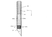
- XZ sectional view of sensor holding bar 21 in Embodiment 3 of the present disclosure XZ sectional view of sensor holding bar 21 and needle 32 when sensor holding bar 21 in Embodiment 3 of the present disclosure is installed in needle hole 31
- XY sectional view of sensor fixing unit 105 according to Embodiment 3 of the present disclosure XZ sectional view of sensor fixing portion 105 and open / close bar 26 in a state outside needle hole 31 of needle 32 in Embodiment 3 of the present disclosure
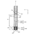
- XZ sectional view of sensor holding bar 21 in Embodiment 4 of the present disclosure XZ sectional view of sensor holding bar 21 and needle 32 when sensor holding bar 21 in Embodiment 4 of the present disclosure is installed in needle hole 31 XZ sectional view of sensor fixing portion 205 and opening / closing bar 206 in the state outside needle hole 31 of needle 32 in Embodiment 4 of the present disclosure
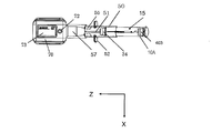
- YZ sectional view of sensor fixing portion 305 and open / close bar 306 in the state outside needle hole 31 of needle 32 in Embodiment 5 of the present disclosure The figure which shows the outline of the sensor embedding apparatus 1000 in illustrative embodiment of this indication.
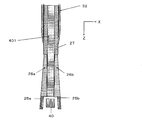
- XZ sectional view of sensor holding bar 21 and push bar 401 in the sixth embodiment of the present disclosure XZ sectional view of sensor holding bar 21, needle 32, and push bar 401 when sensor holding bar 21 and push bar 401 in Embodiment 6 of the present disclosure are installed in needle hole 31.
- XY sectional view of sensor fixing unit 25 according to the sixth embodiment of the present disclosure.
- YZ sectional view of sensor holding bar 21 and push-out bar 401 in the eighth embodiment of the present disclosure YZ sectional view of sensor holding bar 21, needle 32 and push bar 401 when sensor holding bar 21 and push bar 401 are installed in needle hole 31 in the eighth embodiment of the present disclosure.
- YZ sectional view of sensor fixing portion 305, open / close bar 306, and push bar 401 in the state outside needle hole 31 of needle 32 in the eighth embodiment of the present disclosure YZ sectional view of sensor fixing unit 305, opening / closing bar 306, push-out bar 401, and sensor 40 in a state where sensor fixing unit 305 releases the fixing of sensor 40.
- the inclination of the sensor within the subject It is beneficial to control. That is, for example, when detection is performed from the skin surface of a living body, it is beneficial to control the sensing area of the sensor surface to face the skin surface.
- the skin is composed of an epidermis tissue having a thickness of about 0.2 to 0.5 mm on the surface of the living body and a dermis tissue having a thickness of about 0.5 to 2 mm located under the epidermis tissue.
- Light irradiated from outside the living body is diffused, scattered or absorbed under the skin. For this reason, when the sensor is located deep in the skin and the sensor surface having the sensing region does not face the skin surface, the intensity of light applied to the sensor becomes weak. Furthermore, the light generated from the sensor surface is also weakened. By these, the light intensity detected percutaneously becomes weak.
- the sensor When using an injection device as in the prior art to embed a sensor, the sensor may rotate in the injection needle. For this reason, the sensing area of the sensor cannot always be embedded in a state directed in a predetermined direction (for example, the skin surface). Therefore, for example, it is not possible to obtain sensitivity for detection of the state of the subject (for example, measurement of glucose concentration).
- the sensor embedding device is a sensor embedding device that embeds a sensor having a sensing region for detecting the state of the subject in the subject.
- a sensor embedding device includes a needle, a sensor holding unit, and a movable part.
- the needle has a hole and is inserted into the subject.
- the sensor holding means holds the sensor so that the sensor is embedded in the subject with the sensing area facing a predetermined direction.
- the movable part moves the sensor into the subject by sliding the sensor holding means inside the hole.
- the sensor holding means has a first fixing portion and a second fixing portion.
- the sensor may be held by being sandwiched between the first fixing portion and the second fixing portion.
- the holding of the sensor is released.
- the distance between the first fixing portion and the second fixing portion is a distance that can hold the sensor inside the hole, and is outside the hole than the distance inside the hole. Is a distance at which the holding of the sensor is released.
- the first fixed portion is connected to the movable portion by the first connecting means. Assuming that the angle formed by the first connecting means and the sliding direction of the movable portion is the first angle, the first angle increases when the first connecting means goes out of the hole. The distance between the fixed part and the second fixed part may be increased.
- the first connecting means is a first opening / closing bar having elasticity, and the first opening / closing bar is movable so that the first angle is a predetermined first initial angle outside the hole. It is fixed to the part. Inside the hole, the first opening / closing rod is deformed so that the first angle is smaller than the first initial angle, and when the first opening / closing rod goes out of the hole, the first opening / closing rod The first angle may be increased to the first initial angle by restoring the deformation.
- the second fixed portion is connected to the movable portion by the second connecting means. Assuming that the angle formed between the second connecting means and the sliding direction of the movable portion is the second angle, when the second connecting means goes out of the hole, the second angle increases, The distance between the fixed part and the second fixed part may be increased.
- the second connecting means is a second open / close bar having elasticity, and the second open / close bar is movable so that the second angle is a predetermined second initial angle outside the hole. It is fixed to the part. Inside the hole, the second opening / closing rod is deformed so that the second angle is smaller than the second initial angle, and when the second opening / closing rod goes out of the hole, the second opening / closing rod By restoring the deformation, the second angle may be increased to the second initial angle.
- At least one of the first connecting means and the second connecting means may be provided so as not to contact the inner wall of the hole inside the hole.
- the sensor embedding device further includes a sensor holding release unit that releases the holding of the sensor by the sensor holding unit.
- the sensor holding release unit may release the holding of the sensor by the sensor holding unit by increasing the distance between the first fixing unit and the second fixing unit.
- the sensor holding release means includes an extrusion rod, the first fixed portion is connected to the movable portion by the first opening / closing rod, and the extrusion rod is located at the center of the hole rather than the first opening / closing rod. Located on the side.
- the sensor holding release means may widen the distance between the first fixing portion and the second fixing portion by pushing the first opening / closing rod away from the outer peripheral side of the hole with the pushing rod.
- the second fixed portion is connected to the movable portion by a second opening / closing rod, and the push-out rod is positioned closer to the center of the hole than the second opening / closing rod.
- the sensor holding release means may widen the distance between the first fixing portion and the second fixing portion by pushing the second opening / closing rod away from the outer peripheral side of the hole by the pushing rod.
- the movable part includes a hollow support rod.
- the support bar may be inserted into the hole and slide inside the hole, and the push bar may be inserted inside the support bar and slide inside the support bar.
- the first fixing portion is located on the first side surface side of the sensor, and the second fixing portion is located on the opposite side to the first side surface side of the sensor.
- the first fixing part is located on the side where the sensing area of the sensor is located, and the second fixing part is located on the side opposite to the side where the sensing area of the sensor is located.
- At least one of the first fixed portion and the second fixed portion has a semi-cylindrical shape.
- the first fixed portion and the second fixed portion are in contact with each other in a state where the sensor is held.
- the needle may be inserted from the surface of the subject.
- the predetermined direction may be on the surface side of the subject.
- the senor is used to measure or monitor a test substance in vivo using optical techniques.
- the optical technique may be surface enhanced Raman scattering spectroscopy or surface enhanced fluorescence spectroscopy.
- a sensor embedding device includes a plunger, a needle guiding means, a cylinder into which the plunger is inserted, a contact portion, a needle extraction fixing means, a sensor holding means extraction fixing means, and an implantation determination means.
- the plunger holds the needle, the movable part, and the sensor holding means.
- the needle guiding means holds the needle, the movable part, and the sensor holding means in a state where the needle, the movable part, and the sensor holding means are moved to a predetermined position by sliding the plunger.
- the contact portion is attached to the cylinder at a predetermined angle, has a hole through which the needle passes, and contacts the surface of the subject.
- the needle extraction fixing means fixes the needle extracted from the inside of the subject in the plunger.
- the sensor holding means pull-out fixing means fixes the movable part pulled out from the inside of the subject and the sensor holding means in the plunger.
- the embedding determination means notifies the user of the success or failure of embedding.
- the contact portion may have attachment means for attaching to the surface of the subject.
- a sensor embedding system is a sensor embedding system for embedding a sensor in a subject.
- a sensor embedding system according to an aspect includes a sensor and the sensor embedding device according to any one of the above.
- the sensor includes a sensing region for detecting the state of the subject and a held portion. The sensor is held by holding the held portion between the first fixing portion and the second fixing portion.
- the first fixing portion and the second fixing portion are formed with recesses.
- the sensor may be held by sandwiching the held portion of the sensor between the concave portion of the first fixed portion and the concave portion of the second fixed portion.
- the senor is a sensor chip having a flat plate shape.
- the sensing area may be formed on a part of the main surface of the sensor chip, and the held part may be a part where the sensing area in the sensor chip is not formed.
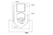
- FIG. 20 is a diagram illustrating an outline of the sensor embedding device 1000 according to an exemplary embodiment of the present disclosure.
- the sensor embedding device 1000 embeds a sensor in a subject.
- the sensor has a sensing area for detecting the state of the subject.
- the sensor embedding device 1000 includes a needle 1100, a sensor holding unit 1200, and a movable part 1300.
- Needle 1100 has a hole. The needle 1100 is inserted into the subject.
- the sensor holding means 1200 holds the sensor so that the sensor is embedded in the subject with the sensing area facing a predetermined direction.
- the movable part 1300 moves the sensor to the inside of the subject by sliding the sensor holding means 1200 inside the hole.
- the senor can be embedded in the subject with the sensing area facing a predetermined direction.
- the sensor can be embedded with the sensor surface on which the sensing region is located facing the skin surface of the living body.
- a living body for example, a human body or an animal
- a living body for example, a human body or an animal
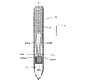
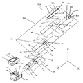
- FIG. 1 is an exploded view showing an example of the configuration of the sensor embedding device 100 according to Embodiment 1 of the present disclosure.
- FIG. 1 shows an X axis, a Y axis, and a Z axis that are orthogonal to each other.
- an X axis, a Y axis, or a Z axis may be shown.
- the sensor embedding device 100 shown in FIG. 1 includes a plunger unit 80, a cylinder unit 57, a main body unit 60, and a detector 70.
- the plunger unit 80 includes a sensor holding unit 20, a needle unit 30, and a plunger 10.
- the plunger 10 has sensor holding unit set holes 15 at two positions located symmetrically.
- the sensor holding unit 20 includes a sensor holding bar 21 and a sensor holding bar fixing portion 22.
- the sensor holding rod fixing portion 22 is provided at the end of the sensor holding rod 21.
- the sensor holding bar fixing portion 22 is provided with a fixing claw 24 and a needle unit connecting surface 23.
- the sensor holding unit 20 is fixed in the plunger 10 by fitting the fixing claw 24 into the sensor holding unit set hole 15.
- the plunger 10 includes a needle unit guide slit 14, a needle unit setting hole 12, and a needle unit pullback release slit 13.
- the needle unit set hole 12 and the needle unit pull-back release slit 13 are formed in the plunger 10 at two locations, respectively.
- the arrangement of the needle unit setting hole 12 and the needle unit retracting release slit 13 is symmetrical in the plunger 10.
- the needle unit 30 includes a needle unit holding claw 36, a needle 32, a sensor holding unit fixing release claw 37, a guide 35, and a slide lever 34.
- the needle unit 30 is fixed in the plunger 10 by fitting the needle unit holding claw 36 into the needle unit setting hole 12.
- the needle 32 has a needle hole 31 through which the sensor 40 and the sensor holding bar 21 pass.
- the cylinder unit 57 includes a needle unit mounting fixing slit 56, a slit 51, a finger hooking portion 52 for pushing the plunger unit 80, a guide convex portion 53 for mounting the cylinder unit 57 to the main unit 60, a lock claw 54, And a cylinder 50.
- the main body unit 60 includes a guide groove 61 for attaching the cylinder unit 57, a lock groove 62, a detector mounting set claw 63, and an embedding confirmation window 64.
- the cylinder unit 57 is connected to the main unit 60 by fitting the guide protrusion 53 into the guide groove 61 and the lock claw 54 into the lock groove 62, respectively.
- a display 73 and a confirmation button 72 are provided on the upper surface of the detector 70.
- a detector set groove 71 is provided on the side surface of the detector 70. The detector 70 is connected to the main unit 60 by fitting the detector mounting set claw 63 into the detector setting groove 71.
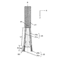
- FIG. 2 is a schematic cross-sectional view of the sensor holding rod 21 cut along a plane parallel to the XZ plane (see FIG. 1).
- the sensor holding bar 21 includes a support bar 27, a pair of opening / closing bars 26, and a sensor fixing unit 25.
- the sensor holding means includes a pair of opening / closing bars 26 and a sensor fixing portion 25.
- the sensor fixing part 25 includes a first fixing part 25a and a second fixing part 25b.
- the sensor holding means holds the sensor by sandwiching the sensor between the first fixing portion and the second fixing portion.
- the pair of opening / closing bars 26 includes a first opening / closing bar 26a (first connecting means) and a second opening / closing bar 26b (second connecting means).
- the configuration of the support rod 27, the opening / closing rod 26, and the sensor fixing portion 25 when the sensor 40 having a 1 mm square and a thickness of 0.2 mm is embedded will be described.
- the size of the sensor 40, the configuration of the support rod 27, the opening / closing rod 26, and the sensor fixing portion 25 are not limited to this example. The configuration can be changed as appropriate depending on the size of the sensor 40.
- the length (L1) of the opening / closing bar 26 shown in FIG. 2 is, for example, 5 mm.
- the support rod 27 may have a cylindrical shape.
- the diameter of the support bar 27 is designed so that it can move without friction within the needle.
- the diameter of the support rod 27 is 1.65 mm, for example.
- One end of the opening / closing rod 26 is fixed in a circular side surface of the support rod 27, for example.
- the distance (W) between the first opening / closing rod 26a and the second opening / closing rod 26b at the place where the support rod 27 and the opening / closing rod 26 are fixed is, for example, about 0.8 mm.
- the first angle (R1a) that is an angle formed between the first opening / closing bar 26a and the center line B of the support bar 27 is configured to be, for example, about 4 degrees as the first initial angle.
- the second angle (R1b), which is an angle formed by the second opening / closing bar 26b and the center line B of the support bar 27, is configured to be, for example, about 4 degrees as the second initial angle. Yes.
- the value of the length L1, the first initial angle, and the second initial angle are not limited to specific values as long as the sensor 40 can be fixed and released.
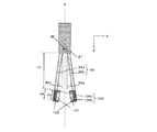
- FIG. 3 is a schematic cross-sectional view when the sensor holding bar 21 and the needle 32 are cut along a plane parallel to the XZ plane when the sensor holding bar 21 is installed in the needle hole 31.
- the first fixing portion 25a is located on the first side surface side of the sensor.
- the second fixing portion 25b is located on the side opposite to the first side surface of the sensor.
- the thickness of the needle 32 may be 14G, for example. That is, the inner diameter may be 1.69 mm and the outer diameter may be 2.11 mm.
- the opening / closing bar 26 is deformed.
- the pair of opening / closing bars 26 are substantially parallel.
- the first angle R1a (see FIG. 2) is approximately 0 degrees inside the needle hole 31.
- the second angle R1b (see FIG. 2) is approximately 0 degrees inside the needle hole 31.
- the sensor 40 is fixed by the sensor fixing portion 25.
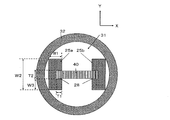
- FIG. 4 is a schematic cross-sectional view (cross-sectional view taken along the line AA shown in FIG. 3) when the sensor fixing portion 25 is cut along a plane parallel to the XY plane.
- the sensor fixing part 25 (first fixing part 25a, second fixing part 25b) includes a recess 28 into which the sensor 40 is fitted.
- the width (W1) in the X direction of the sensor fixing portion 25 is 0.35 mm
- the width (W2) in the Y direction is 0.8 mm
- the depth (T1) of the recess 28 is 0.15 mm.
- the width (T2) of the concave portion 28 is 0.2 mm
- the thickness (W3) from the bottom surface of the sensor fixing portion 25 to the concave portion 28 is 0.3 mm.
- the width T2 is slightly larger than the sensor thickness.
- the open / close bar 26 (first open / close bar 26a, second open / close bar 26b) has a prismatic shape, the width in the X direction is 0.35 mm, and the width in the Y direction is 0.8 mm.
- the material of the opening / closing rod 26 and the sensor fixing portion 25 is not limited to a specific material as long as it is elastic and can be processed.
- Examples of the material of the opening / closing rod 26 and the sensor fixing portion 25 are metal, alloy, resin, and the like.
- processing methods of the support rod 27, the opening / closing rod 26, and the sensor fixing portion 25 are cutting processing, laser processing, and the like. As long as these materials can be processed, the processing method is not limited to a specific method.
- the width (S2) of the concave portion 28 in the Z direction is, for example, 1.1 mm (see FIG. 2).
- the width (S1) in the Z direction of the sensor fixing portion 25 is, for example, 1.5 mm (see FIG. 2).
- the sizes of S2 and S1 are not limited to 1.1 mm and 1.5 mm.
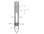
- FIG. 5 is a schematic cross-sectional view of the sensor fixing portion 25 and the opening / closing bar 26 in a state outside the needle hole 31 of the needle 32 when cut along a plane parallel to the XZ plane.
- the deformation is restored by the elasticity of the first open / close bar 26a and the second open / close bar 26b.
- the bar 26 spreads out.
- the first angle R1a increases to the first initial angle (about 4 degrees).
- the second angle R1b increases to the second initial angle (about 4 degrees).
- the distance between the first fixing portion 25a and the second fixing portion 25b is a distance at which the sensor can be held inside the hole.
- the distance between the first fixing portion 25a and the second fixing portion 25b is a distance at which the sensor is released from the outside of the hole. The distance at which the sensor is released is greater than the distance inside the hole.
- the first fixing portion 25a is connected to the support rod 27 which is a part of the movable portion by the first opening / closing rod 26a which is the first connecting means. Yes.
- the first opening / closing bar 26a which is the first connecting means, comes out of the hole, the first angle R1a increases. Thereby, the distance between the 1st fixing
- the first angle is an angle formed by the first connecting means and the sliding direction of the movable portion (the direction of the center line B of the support rod 27, see FIG. 2).
- the first opening / closing bar 26a has elasticity. Further, the first opening / closing bar 26a is fixed to the support bar 27 which is a part of the movable part so that the first angle R1a becomes a predetermined first initial angle outside the hole. At this time, in the hole, the first opening / closing bar 26a is deformed so that the first angle R1a is smaller than the first initial angle. Then, when the first opening / closing bar 26a goes out of the hole, the deformation of the first opening / closing bar 26a is restored, so that the first angle R1a is increased to the first initial angle.
- the second fixed portion 25b is connected to the support rod 27 which is a part of the movable portion by the second opening / closing rod 26b which is the second connecting means.
- the second opening / closing bar 26b which is the second connecting means, goes out of the hole, the second angle R1b increases. Thereby, the distance between the 1st fixing
- the second angle is an angle formed by the second connecting means and the sliding direction of the movable portion (the direction of the center line B of the support rod 27, see FIG. 2).
- the second opening / closing bar 26b has elasticity.
- the second opening / closing bar 26b is fixed to the support bar 27 which is a part of the movable portion so that the second angle R1b becomes a predetermined second initial angle outside the hole.
- the second opening / closing bar 26b is deformed so that the second angle R1b is smaller than the second initial angle.
- the deformation of the second opening / closing rod 26b is restored, so that the second angle R1b is increased to the second initial angle.
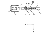
- FIG. 6 is a top view of the sensor embedding device 100.
- a rib 55 for stopping the needle unit 30 from sliding is formed inside the cylinder 50.
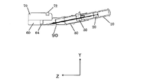
- FIG. 7 is a side sectional view of the sensor embedding device 100.
- the cylinder 50 is inclined with respect to the living body contact surface 90.
- the angle formed between the cylinder 50 and the living body contact surface 90 is, for example, about 11 degrees.
- the rib 55 is configured such that the living body insertion length of the needle 32 is about 15 mm.
- the senor 40 can be embedded at a depth of about 1 mm in the living body.
- the living body contact surface 90 may have an adhesive portion with a cover sheet (not shown) in order to fix the sensor embedding device 100 to the living body.
- the senor 40 may be implanted under the skin of a living body. Further, the living body contact surface 90 may contact the skin of the living body.
- the sensor holding unit 20 having the sensor holding bar fixing portion 22 having the fixing claw 24 arranged on the side surface is arranged so that the fixing claw 24 is placed in the sensor holding unit set hole 15 at the rear of the plunger 10. Insert into.
- the sensor 40 is sandwiched in the sensor fixing portion 25, and the sensor holding rod 21 is inserted into the needle hole 31 that is vacant in the needle 32 of the needle unit 30.
- the needle unit 30 is held by the plunger 10 by placing the needle unit holding claw 36 disposed on the side surface of the needle unit 30 in the needle unit setting hole 12 in front of the plunger 10.
- the guide 35 of the needle unit 30 is inserted into the needle unit mounting fixing slit 56 of the cylinder 50, and the plunger 10 is fixed when the guide 35 enters the slit 51. Thereby, the plunger 10 holding the sensor holding unit 20 and the needle unit 30 is held by the cylinder unit 57.
- the guide groove 61 in the main unit 60 and the guide convex portion 53 of the cylinder unit 57 are aligned, and the cylinder unit 57 holding the plunger 10 is pushed in until the lock groove 62 of the main unit 60 and the lock claw 54 of the cylinder unit 57 are aligned.
- the cylinder unit 57 and the main unit 60 are connected.
- the detector 70 After connecting the cylinder unit 57 and the main unit 60, the detector 70 is pushed into the main unit 60 so that the detector mounting set claw 63 of the main unit 60 and the detector set groove 71 of the detector 70 are aligned. Thereby, the detector 70 and the main body unit 60 are connected.
- the user When embedding the sensor 40, the user removes the cover sheet, if necessary, and attaches the living body contact surface 90 to the living body surface with the adhesive portion.
- FIG. 6 and FIG. A finger is put on the finger rest 52 in the middle of the cylinder unit 57, and the rear end of the plunger 10 is pushed with the thumb. Thereby, the plunger 10 slides in the cylinder 50, and the needle unit 30 and the sensor holding unit 20 fixed to the plunger 10 also slide simultaneously. Thereby, the needle 32 protrudes from the hole of the living body contact surface 90 and is inserted into the living body.
- the support rod 27 slides inside the needle hole 31 (see FIGS. 3 and 5). Along with this, the sensor fixing portion 25 connected to the support rod 27 also slides.
- the open / close bar 26 is also moved out of the needle hole 31, and the sensor 40 is released by the sensor fixing portion 25 spreading.
- the finger is removed from the finger rest 52 of the cylinder unit 57, and the slide lever 34 in the needle unit 30 is pulled up. Accordingly, the needle 32 comes out of the living body, the needle unit 30 hits the needle unit connecting surface 23 of the sensor holding unit 20, and the sensor holding unit 20 and the needle unit 30 are fixed.
- the sensor holding unit 20 is released from the fixing to the plunger 10 by the sensor holding unit fixing release claw 37 located behind the needle unit 30.
- a confirmation button 72 on the detector 70 is pressed to confirm whether the sensor 40 is correctly embedded. Then, the detector 70 irradiates the living body with a laser. The laser light passes through the confirmation window 64. When the light reflected from the surface of the sensor 40 is detected by the detector 70, the sensor embedding device 100 notifies the user that the embedding is successful. When light is not detected, the sensor embedding device 100 notifies the user that the embedding has failed.
- the sensor embedding device 100 is removed from the living body and the implantation is finished.
- the movable part is configured by the support rod 27 and the like.
- the movable part moves the sensor into the subject by sliding the sensor holding means including the sensor fixing part 25 and the like inside the needle hole 31.
- the needle is inserted from the surface of the subject.
- the sensor holding means holds the sensor inside the subject so that the sensing area of the sensor faces the surface side of the subject.
- the surface of the subject may be biological skin.
- the senor may be used to measure or monitor a test substance (analyte) in the living body using an optical technique.
- the optical technique may be surface-enhanced Raman scattering spectroscopy, surface-enhanced fluorescence spectroscopy, or the like.
- the sensor embedding device includes a plunger, a needle guiding unit, a cylinder into which the plunger is inserted, a contact portion, a needle extraction fixing unit, a sensor holding unit extraction fixing unit, and an embedded determination.
- the plunger holds the needle, the movable part, and the sensor holding means.
- the needle guiding means holds the needle, the movable part, and the sensor holding means in a state where the needle, the movable part, and the sensor holding means are moved to a predetermined position by sliding the plunger.
- the contact portion is attached to the cylinder at a predetermined angle, has a hole through which the needle passes, and contacts the surface of the subject.
- the needle extraction fixing means fixes the needle extracted from the inside of the subject in the plunger.
- the sensor holding means pull-out fixing means fixes the movable part pulled out from the inside of the subject and the sensor holding means in the plunger.
- the embedding determination means notifies the user of the success or failure of embedding.
- the configuration including the slit 51, the rib 55, the needle unit mounting fixing slit 56, and the like is illustrated as the needle guiding means.
- the living body contact surface 90 is exemplified as the contact portion.
- the configuration including the slide lever 34, the guide 35, etc. is illustrated as the needle pull-out fixing means.
- a configuration including the sensor holding unit fixing release claw 37, the needle unit connecting surface 23, and the like is illustrated as the sensor holding unit pull-out fixing unit.
- the detector 70 is illustrated as an embedding determination unit.
- the sensor embedding device according to Embodiment 1 may include an attaching means for attaching the contact portion to the surface of the subject.
- an adhesive portion is illustrated as an attachment means.
- the senor can be embedded at a predetermined depth by using the sensor embedding device 100 of the first embodiment. Furthermore, the sensor can be embedded with the sensor surface facing the surface of the living body.
- the shape of the opening / closing rod 26 is not limited to a prism.
- the shape of the opening / closing bar 26 may be a prism, a cylinder, a semi-cylinder, or a polygon.
- the difference between the present embodiment and the first embodiment is that the sensor fixing portion 95 of the present embodiment has a different shape from the sensor fixing portion 25 of the first embodiment.
- the configuration other than the sensor fixing unit 95 may be the same as that of the first embodiment. For this reason, common reference numerals are used to describe components having substantially the same function.
- FIG. 8 is a schematic cross-sectional view when the sensor fixing portion 95 is cut along a plane parallel to the XY plane.
- FIG. 8 is a cross-sectional view taken along the line AA shown in FIG. 3, as in FIG.
- a configuration of the sensor fixing unit 95 when the sensor 40 having a 1 mm square and a thickness of 0.2 mm is embedded will be described.
- the size of the sensor 40, the configuration of the support rod 27, the opening / closing rod 26, and the sensor fixing portion 95 are not limited to this example. The configuration can be changed as appropriate depending on the size of the sensor 40.
- the sensor fixing portion 95 includes a first fixing portion 95a and a second fixing portion 95b. As shown in the drawing, each shape of the first fixing portion 95a and the second fixing portion 95b is a semi-cylinder.
- the sensor fixing part 95 includes a recess 96 into which the sensor 40 is fitted.
- the thickness of the needle 32 is, for example, 14G. That is, the inner diameter may be 1.69 mm and the outer diameter may be 2.11 mm.
- the radius of curvature (r1) of the sensor fixing portion 95 is 0.45 mm
- the depth (T3) of the concave portion 96 is 0.15 mm
- the width (T4) of the concave portion 96 is 0.2 mm. It is.
- the width T4 is slightly larger than the sensor thickness.
- the width of the concave portion 96 in the Z direction is, for example, 1.1 mm, and the width of the sensor fixing portion 95 in the Z direction is, for example, 1.5 mm.
- the width of the concave portion 96 in the Z direction and the width of the sensor fixing portion 95 in the Z direction are not limited to 1.1 mm and 1.5 mm, respectively.
- the first fixing portion 95a and the second fixing portion 95b have a semi-cylindrical shape.
- At least one of the first fixing portion 95a and the second fixing portion 95b may have a semi-cylindrical shape.
- At least one of the first fixing portion 95a and the second fixing portion 95b is a semi-cylinder.
- the number of corners in the sensor fixing portion 95 can be reduced as compared with a prism or the like. Therefore, it is possible to reduce damage to the subject (for example, living tissue) at the time of implantation.
- the difference between the present embodiment and the first and second embodiments is that the sensor fixing portion 105 of the present embodiment is different from the sensor fixing portion 25 of the first embodiment and the sensor fixing portion 95 of the second embodiment. It is a point with.
- the configuration other than the sensor fixing unit 105 may be the same as that of the first embodiment. For this reason, common reference numerals are used to describe components having substantially the same function.
- FIG. 9 is a schematic cross-sectional view when the sensor holding rod 21 is cut along a plane parallel to the XZ plane (see FIG. 1).
- the sensor holding bar 21 in the present embodiment includes a support bar 27, a pair of opening / closing bars 26, and a sensor fixing part 105.
- the sensor fixing unit 105 includes a first fixing unit 105a and a second fixing unit 105b.
- the configuration of the support rod 27, the opening / closing rod 26, and the sensor fixing portion 105 when the sensor 40 having a 1 mm square and a thickness of 0.2 mm is embedded will be described.
- the size of the sensor 40, the configuration of the support rod 27, the opening / closing rod 26, and the sensor fixing portion 105 are not limited to this example. The configuration can be changed as appropriate depending on the size of the sensor 40.
- the length (L2) of the opening / closing bar 26 shown in FIG. 9 is, for example, 5 mm.
- the support rod 27 may be cylindrical.
- the diameter of the support bar 27 is designed so that it can move without friction within the needle.
- the diameter of the support rod 27 is 1.65 mm, for example.
- One end of the opening / closing rod 26 is fixed in a circular side surface of the support rod 27, for example.
- the distance (W) between the first opening / closing rod 26a and the second opening / closing rod 26b at the place where the support rod 27 and the opening / closing rod 26 are fixed is, for example, about 0.8 mm.
- the first angle (R2a), which is the angle formed by the first opening / closing bar 26a and the center line B of the support bar 27, is configured to be, for example, about 8 degrees as the first initial angle.
- the second angle (R2b), which is an angle formed by the second opening / closing bar 26b and the center line B of the support bar 27, is configured to be, for example, about 8 degrees as the second initial angle. Yes.
- the shape of the opening / closing bar 26 may be the same as that of the first embodiment.
- two concave portions 106 and a concave portion 107 are formed in each of the first fixing portion 105a and the second fixing portion 105b.
- the value of the length L2, the first initial angle, and the second initial angle are not limited to specific values as long as the sensor 40 can be fixed and unlocked.
- FIG. 10 is a schematic cross-sectional view when the sensor holding bar 21 and the needle 32 are cut along a plane parallel to the XZ plane when the sensor holding bar 21 of the present embodiment is installed in the needle hole 31. is there.
- the thickness of the needle 32 is, for example, 14G. That is, the inner diameter may be 1.69 mm and the outer diameter may be 2.11 mm.
- the first angle R ⁇ b> 2 a is about 0 degrees inside the needle hole 31.
- the second angle R2b is about 0 degrees inside the needle hole 31.
- the senor 40 is fixed by the sensor fixing unit 105.
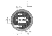
- FIG. 11 is a schematic cross-sectional view (cross-sectional view taken along line CC shown in FIG. 10) when the sensor fixing portion 105 is cut along a plane parallel to the XY plane.
- the sensor fixing portion 105 (first fixing portion 105a, second fixing portion 105b) includes a recess 106 into which the sensor 40 is fitted and a recess 107 for avoiding contact with the sensor surface. I have.
- the first fixing portion 105 a and the second fixing portion 105 b are in contact with each other while the sensor 40 is held.
- each of the first fixing portion 105a and the second fixing portion 105b has a semi-cylindrical shape.
- the radius of curvature (r2) of the sensor fixing portion 105 is about 0.8 mm
- the depth (T5) of the concave portion 106 is 0.15 mm
- the width (T6) of the concave portion 106 is 0.2 mm.
- the depth (T7) of the recess 107 is about 0.4 mm
- the width (T8) of the recess 107 is 0.6 mm.
- the width T6 is slightly larger than the sensor thickness.
- the open / close bar 26 (first open / close bar 26a, second open / close bar 26b) has a prismatic shape, the width in the X direction is 0.3 mm, and the width in the Y direction is 0.8 mm.
- the material of the opening / closing rod 26 and the sensor fixing portion 105 is not limited to a specific material as long as it is elastic and can be processed. Examples of the material of the opening / closing rod 26 and the sensor fixing portion 105 are metal, alloy, resin, and the like.
- processing methods for the support rod 27, the opening / closing rod 26, and the sensor fixing portion 105 include cutting processing and laser processing. As long as these materials can be processed, the processing method is not limited to a specific method.
- the width (S3) in the Z direction of the recesses 106 and 107 is, for example, 1.1 mm (see FIG. 9).
- the width (S4) in the Z direction of the sensor fixing portion 105 is, for example, 1.5 mm (see FIG. 9).
- the sizes of S3 and S4 are not limited to 1.1 mm and 1.5 mm.
- FIG. 12 is a schematic cross-sectional view of the sensor fixing portion 105 and the opening / closing rod 26 in a state outside the needle hole 31 of the needle 32 taken along a plane parallel to the XZ plane.
- the first angle R2a increases to the first initial angle (about 8 degrees).
- the second angle R2b increases to the second initial angle (about 8 degrees).
- the first fixing portion 105a and the second fixing portion 105b are in contact with each other while the sensor is held.
- the first fixing portion 105a and the second fixing portion 105b can contact each other. For this reason, the sensor 40 can be fixed more stably.
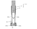
- the difference between the present embodiment and the first embodiment is that the open / close rod 206 and the sensor fixing portion 205 of the present embodiment are different from the open / close rod 26 and the sensor fixing portion 25 of the first embodiment, respectively. It is a point to have. Except for the opening / closing bar 206 and the sensor fixing unit 205, the same configuration as that of the first embodiment may be used. For this reason, common reference numerals are used to describe components having substantially the same function.
- FIG. 13 is a schematic cross-sectional view of the sensor holding rod 21 in the present embodiment cut along a plane parallel to the XZ plane (see FIG. 1).
- the sensor holding bar 21 in this embodiment includes a support bar 27, a pair of opening / closing bars 206, and a sensor fixing unit 205.
- the pair of opening / closing bars 206 includes a first opening / closing bar 206a (first connecting means) and a second opening / closing bar 206b (second connecting means).
- the sensor fixing unit 205 includes a first fixing unit 205a and a second fixing unit 205b.
- the configuration of the sensor fixing unit 205 and the opening / closing rod 206 when the sensor 40 having a 1 mm square and a thickness of 0.2 mm is embedded will be described.
- the size of the sensor 40 and the configuration of the sensor fixing unit 205 and the opening / closing bar 206 are not limited to this example. The configuration can be changed as appropriate depending on the size of the sensor 40.
- the length (L3) of the opening / closing bar 206 shown in FIG. 13 is, for example, 5 mm.
- the support rod 27 may be cylindrical.
- the diameter of the support bar 27 is designed so that it can move without friction within the needle.
- the diameter of the support rod 27 is 1.65 mm, for example.
- One end of the opening / closing bar 206 is fixed, for example, in a circular side surface of the support bar 27.
- the opening / closing bar 206 is fixed to the support bar 27 so that the longitudinal directions thereof are substantially parallel to each other.
- the first angle (R4a), which is the angle formed by the first opening / closing bar 206a and the center line B of the support bar 27, is configured to be, for example, about 0 degrees as the first initial angle. (See FIG. 14 described later).
- the second angle (R4b), which is an angle formed by the second opening / closing bar 206b and the center line B of the support bar 27, is configured to be, for example, about 0 degrees as the second initial angle. (See FIG. 14 described later).
- the distance (W) between the first opening / closing rod 206a and the second opening / closing rod 206b at the place where the support rod 27 and the opening / closing rod 206 are fixed is, for example, about 0.8 mm.
- the sensor fixing unit 205 is configured such that an angle (R3) formed with the opening / closing bar 206 is about 5 degrees.
- the value of the length L3 and the value of the angle R3 are not limited to 5 mm and 5 degrees, respectively.
- the value of the length L3 and the value of the angle R3 may be values that can fix and release the sensor 40, and are not limited to specific values.
- FIG. 14 is a schematic cross-sectional view when the sensor holding bar 21 and the needle 32 are cut along a plane parallel to the XZ plane when the sensor holding bar 21 of the present embodiment is installed in the needle hole 31. is there.
- the thickness of the needle 32 is, for example, 14G. That is, the inner diameter may be 1.69 mm and the outer diameter may be 2.11 mm.
- the second angle (R4b) that is an angle formed by the second opening / closing rod 206b and the center line B of the support rod 27 is, for example, about ⁇ 5 degrees.
- the senor 40 is sandwiched by the sensor fixing unit 205, and the sensor 40 can be fixed.
- At least one of the first opening / closing bar 206a and the second opening / closing bar 206b is not in contact with the inner wall of the needle hole 31 inside the needle hole 31.
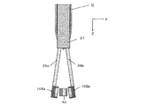
- FIG. 15 is a schematic cross-sectional view of the sensor fixing portion 205 and the opening / closing rod 206 in a state outside the needle hole 31 of the needle 32, taken along a plane parallel to the XZ plane.
- the first angle R4a increases to the first initial angle (about 0 degrees).
- the second angle R4b increases to the second initial angle (about 0 degrees).
- the structure of the sensor fixing unit 205 may be the same as that of the sensor fixing unit 25 of the first embodiment. However, the present embodiment is different from the first embodiment in that the sensor fixing unit 205 is fixed to the opening / closing rod 206 at an angle of, for example, about 5 degrees.
- the shape of the sensor fixing unit 205 is not limited to a specific shape, and the same shape as the sensor fixing unit 95 of Embodiment 2 may be adopted by changing the configuration.
- the same shape as that of the sensor fixing unit 105 of the third embodiment may be adopted by appropriately changing the configuration.
- the first connecting means (first opening / closing bar 206a) and the second connecting means (second opening / closing bar 206b) are provided in the needle hole 31. Is provided so as not to contact the inner wall of the needle hole 31 (may be referred to as the inner wall of the needle 32).
- the needle hole It may be provided so as not to contact the inner wall of 31.
- the fourth embodiment it is possible to reduce a portion of the sensor holding rod 21 that may come into contact with the inner wall of the needle hole 31. Thereby, a sensor can be inserted more smoothly.
- the difference between the present embodiment and the first to fourth embodiments is that the sensor fixing unit 305 of the present embodiment fixes the sensor 40 from above and below.
- FIG. 16 is a schematic cross-sectional view of the sensor holding rod 21 in the present embodiment cut along a plane parallel to the YZ plane (see FIG. 1).
- the sensor holding bar 21 in this embodiment includes a support bar 27, a pair of opening / closing bars 306, and a sensor fixing part 305.
- the pair of opening / closing bars 306 includes a first opening / closing bar 306a (first connecting means) and a second opening / closing bar 306b (second connecting means).
- the sensor fixing unit 305 includes a first fixing unit 305a and a second fixing unit 305b.
- the sensor surface including the sensing region in the sensor 40 is directed to the first fixing portion 305a side.
- the configuration of the support rod 27, the opening / closing rod 306, and the sensor fixing portion 305 when the sensor 40 having a 1 mm square and a thickness of 0.2 mm is embedded will be described.
- the size of the sensor 40, the configuration of the support rod 27, the opening / closing rod 306, and the sensor fixing portion 305 are not limited to this example. The configuration can be changed as appropriate depending on the size of the sensor 40.
- the length (L4) of the opening / closing bar 306 shown in FIG. 16 is, for example, 5 mm.
- the support rod 27 may be cylindrical.
- the diameter of the support bar 27 is designed so that it can move without friction within the needle.
- the diameter of the support rod 27 is 1.65 mm, for example.
- One end of the opening / closing bar 306 is fixed, for example, in a circular side surface of the support bar 27.
- the distance (W) between the first open / close bar 306a and the second open / close bar 306b at the place where the support bar 27 and the open / close bar 306 are fixed is, for example, about 0.8 mm.
- the first angle (R5a), which is an angle formed by the first opening / closing bar 306a and the center line B of the support bar 27, is configured to be, for example, about 3 degrees as the first initial angle.
- the second angle (R5b), which is an angle formed by the second opening / closing bar 306b and the center line B of the support bar 27, is configured to be, for example, about 3 degrees as the second initial angle. Yes.
- the shape of the opening / closing bar 306 may be the same as that of the first embodiment.
- each of the first fixing portion 305a and the second fixing portion 305b has two recesses 307 and 308 formed therein.
- the value of the length L4, the first initial angle, and the second initial angle are not limited to specific values as long as the sensor 40 can be fixed and unlocked.
- FIG. 17 is a schematic cross-sectional view when the sensor holding bar 21 and the needle 32 are cut along a plane parallel to the YZ plane when the sensor holding bar 21 of the present embodiment is installed in the needle hole 31. is there.
- the thickness of the needle 32 is, for example, 14G. That is, the inner diameter may be 1.69 mm and the outer diameter may be 2.11 mm.
- the pair of opening / closing bars 306 parallel. That is, in the illustrated example, the first angle R5a (see FIG. 16) is approximately 0 degrees inside the needle hole 31. Further, the second angle R5b (see FIG. 16) is about 0 degrees inside the needle hole 31.
- the senor 40 is fixed by the sensor fixing unit 305.
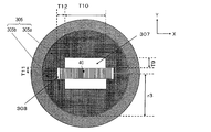
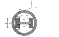
- FIG. 18 is a schematic cross-sectional view (cross-sectional view taken along the line DD shown in FIG. 17) when the sensor fixing portion 305 is cut along a plane parallel to the XY plane.
- the sensor fixing portion 305 (first fixing portion 305a, second fixing portion 305b) includes a concave portion 307 for avoiding contact with the sensor surface and a concave portion 308 into which the sensor 40 is fitted. I have.
- each of the first fixing portion 305a and the second fixing portion 305b has a semi-cylindrical shape.
- the radius of curvature (r3) of the sensor fixing portion 305 is about 0.8 mm
- the depth (T9) of the concave portion 307 is 0.2 mm
- the width (T10) of the concave portion 307 is 0.8 mm.
- the depth (T11) of the recess 308 is 0.1 mm
- the width (T12) of the recess 308 is 0.15 mm.
- the size and shape of the opening / closing bar 306 may be the same as in the third embodiment.
- the material of the opening / closing bar 306 and the sensor fixing portion 305 is not limited to a specific material as long as it is elastic and can be processed.
- Examples of the material of the sensor fixing portion 305 are metal, alloy, resin, and the like.
- processing methods for the support rod 27, the opening / closing rod 306, and the sensor fixing portion 305 include cutting and laser processing. As long as these materials can be processed, the processing method is not limited to a specific method.
- the width (S5) in the Z direction of the recesses 307 and 308 is, for example, 1.1 mm (see FIG. 16).
- the width (S6) in the Z direction of the sensor fixing portion 305 is, for example, 1.5 mm (see FIG. 16).
- the widths S5 and S6 are not limited to 1.1 mm and 1.5 mm, respectively.
- FIG. 19 is a schematic cross-sectional view of the sensor fixing portion 305 and the opening / closing bar 306 in a state outside the needle hole 31 of the needle 32 taken along a plane parallel to the YZ plane.
- the first angle R5a increases to the first initial angle (about 3 degrees).
- the second angle R5b increases to the second initial angle (about 3 degrees).
- the first fixing unit 305a is located on the side (for example, the surface side) where the sensing region of the sensor is located.
- fixed part 305b is located in the reverse side (for example, back side) where the sensing area
- the amount of change in the angle of the opening / closing bar 306 for releasing the sensor 40 is relatively small. For this reason, extraction from the subject is easy, and damage to the subject can be reduced.
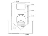
- FIG. 21 is a diagram illustrating an outline of a sensor embedding device 1000A according to another exemplary embodiment of the present disclosure.
- the sensor embedding device 1000A according to another exemplary embodiment of the present disclosure embeds a sensor in a subject.
- the sensor embedding device 1000A includes a needle 1100, a sensor holding unit 1200, a movable part 1300, and a sensor holding release unit 1400.
- the sensor holding release unit 1400 releases the holding of the sensor by the sensor holding unit 1200.
- the senor can be embedded in the subject with the sensing area facing a predetermined direction.
- the sensor can be embedded with the sensor surface on which the sensing region is located facing the skin surface of the living body.
- the sensor holding means can release the sensor holding means with higher accuracy.
- the sensor embedding device includes a sensor holding release means.
- FIG. 22 is an exploded view showing an example of the configuration of the sensor embedding device 100A according to Embodiment 6 of the present disclosure.
- the plunger unit 80A of the sensor embedding device 100A includes the sensor holding unit 20, the needle unit 30, the plunger 10, and the push rod unit 400.
- the sensor holding unit 20 includes a sensor holding bar 21 and a sensor holding bar fixing portion 22.
- the support rod 27 included in the sensor holding rod 21 is hollow.
- the needle unit set hole 12 and the needle unit pull-back release slit 13 are respectively formed at two locations on the plunger 10A.
- the arrangement of the needle unit setting hole 12 and the needle unit pullback release slit 13 is symmetrical in the plunger 10A.
- the push rod unit 400 includes a push rod 401, a push rod holding portion 402, and a push rod slide lever 403.
- the push bar 401 is inserted into the hollow portion of the support bar 27.
- FIG. 23 is a schematic cross-sectional view of the sensor holding bar 21 and the push bar 401 cut along a plane parallel to the XZ plane (see FIG. 22).
- the sensor holding rod 21 includes a hollow support rod 27, a pair of opening / closing rods 26, and a sensor fixing portion 25.
- the extrusion bar 401 has a cylindrical shape.
- the configuration of the support rod 27, the opening / closing rod 26, the sensor fixing portion 25, and the push-out rod 401 when the sensor 40 having a 1 mm square and a thickness of 0.2 mm is embedded will be described.
- the size of the sensor 40, the configuration of the support rod 27, the opening / closing rod 26, the sensor fixing portion 25, and the push-out rod 401 are not limited to this example. The configuration can be changed as appropriate depending on the size of the sensor 40.
- the length (L1) of the opening / closing rod 26 shown in FIG. 23 is, for example, 5 mm.
- the support rod 27 can be cylindrical. In the center of the support rod 27, for example, a 0.8 mm hole is formed.
- the diameter of the support bar 27 is designed so that it can move without friction within the needle. In the present embodiment, the diameter of the support rod 27 is 1.65 mm, for example.
- one end of the opening / closing bar 26 is fixed in a circular side surface of the support bar 27.
- the distance (W) between the first opening / closing rod 26a and the second opening / closing rod 26b at the place where the support rod 27 and the opening / closing rod 26 are fixed is, for example, about 0.8 mm.
- a first angle (R6a) that is an angle formed by the surface of the first opening / closing bar 26a on the center side of the needle 32 and the center line B of the support bar 27 is, for example, about 4 degrees as a first initial angle. It is comprised so that it may become.
- the second angle (R6b), which is an angle formed by the surface of the center of the needle 32 of the second opening / closing bar 26b and the center line B of the support bar 27, is, for example, about 4 as the second initial angle. It is configured to be a degree.
- the value of the length L1, the first initial angle, and the second initial angle are not limited to specific values as long as the sensor 40 can be fixed and released.
- the extrusion bar 401 has a cylindrical shape.
- the diameter of the extrusion bar 401 is, for example, 0.8 mm.
- the push bar 401 is inserted into the hole in the center of the support bar 27.
- FIG. 24 shows a state in which the sensor holding bar 21, the push bar 401, the needle 32, and the sensor 40 are cut along a plane parallel to the XZ plane when the sensor holding bar 21 and the push bar 401 are installed in the needle hole 31. It is typical sectional drawing.
- the first fixing portion 25a is located on the first side surface side of the sensor.
- the second fixing portion 25b is located on the side opposite to the first side surface of the sensor.
- the thickness of the needle 32 is, for example, 14G. That is, the inner diameter may be 1.69 mm and the outer diameter may be 2.11 mm.
- FIG. 25 is a schematic cross-sectional view (cross-sectional view taken along line EE shown in FIG. 24) when the sensor fixing portion 25 is cut along a plane parallel to the XY plane.
- the sensor fixing part 25 (first fixing part 25a, second fixing part 25b) includes a recess 28 into which the sensor 40 is fitted.
- the width (W1) in the X direction of the sensor fixing portion 25 is 0.35 mm
- the width (W2) in the Y direction is 0.8 mm
- the depth (T1) of the recess 28 is 0.15 mm.
- the width (T2) of the recess 28 is 0.2 mm.
- the width T2 is slightly larger than the sensor thickness.
- the fixing part of the opening / closing bar 26 to the support bar 27 may be rectangular.
- the width of the fixed portion in the X direction is, for example, 0.35 mm, and the width in the Y direction is, for example, 0.8 mm.
- the material of the extrusion bar 401 is not limited to a specific material as long as it can be processed.
- Examples of the material of the extrusion bar 401 are metals, alloys, resins, and the like.
- the width (S2) of the concave portion 28 in the Z direction is, for example, 1.1 mm (see FIG. 23).
- the width (S1) in the Z direction of the sensor fixing portion 25 is, for example, 1.5 mm (see FIG. 23).
- the widths S2 and S1 are not limited to 1.1 mm and 1.5 mm, respectively.
- FIG. 26 is a schematic cross-sectional view of the sensor fixing portion 25 and the opening / closing rod 26 in a state outside the needle hole 31 of the needle 32, taken along a plane parallel to the XZ plane.
- the sensor fixing portion 25 and the opening / closing bar 26 come out of the needle hole 31, the distance between the opening / closing bars 26 (the interval between the first opening / closing bar 26a and the second opening / closing bar 26b) is maintained. Therefore, the sensor fixing portion 25 fixes the sensor 40 also outside the needle hole 31.
- FIG. 27 is a schematic cross-sectional view of the sensor fixing unit 25 and the open / close bar 26 cut along a plane parallel to the XZ plane in a state where the push bar 401 is pushed out.
- FIG. 27 shows a state after the push bar 401 is further pushed out toward the sensor fixing portion 25 from the state shown in FIG.
- the sensor embedding device includes the sensor holding release unit that releases the holding of the sensor by the sensor holding unit.
- the sensor holding means includes a first fixing portion 25a and a second fixing portion 25b. At this time, the sensor is held by being sandwiched between the first fixing portion 25a and the second fixing portion 25b. Furthermore, the sensor holding release unit releases the holding of the sensor by the sensor holding unit by increasing the distance between the first fixing unit 25a and the second fixing unit 25b.
- the sensor holding release means includes an extrusion bar 401.
- the first fixed portion 25a is connected to a support rod 27 that is a part of the movable portion by a first opening / closing rod 26a.
- the push bar 401 is located closer to the center of the needle hole than the first opening / closing bar 26a.
- the sensor holding release means widens the distance between the first fixing portion 25a and the second fixing portion 25b by pushing the first opening / closing rod 26a to the outer peripheral side of the needle hole with the pushing rod 401.
- the second fixed portion 25b is connected to the support rod 27 which is a part of the movable portion by the second opening / closing rod 26b.
- the push bar 401 is located closer to the center of the needle hole than the second opening / closing bar 26b.
- the sensor holding release means widens the distance between the first fixing part 25a and the second fixing part 25b by pushing the second opening / closing bar 26b toward the outer peripheral side of the needle hole with the pushing bar 401.
- the movable part includes a hollow support rod 27.
- the support rod 27 is inserted into the needle hole and slides inside the needle hole.
- the push bar 401 is inserted into the support bar 27 and slides inside the support bar 27.
- FIG. 28 is a top view of the sensor embedding device 100A.
- FIG. 29 is a side sectional view of the sensor embedding device 100A.
- the push rod unit 400 is set on the plunger 10A.
- the sensor holding unit 20 having the sensor holding bar fixing portion 22 having the fixing claw 24 disposed on the side surface is inserted into the plunger 10A so that the fixing claw 24 is placed in the sensor holding unit set hole 15 at the rear of the plunger 10A.
- the push bar 401 of the push bar unit 400 is inserted into the hollow portion of the support bar 27 included in the sensor holding unit 20.
- the sensor 40 is inserted into the sensor fixing portion 25, the sensor holding bar 21 is inserted into the needle hole 31, the needle unit 30 is held by the plunger 10A, and the plunger holding the sensor holding unit 20 and the needle unit 30 by the cylinder unit 57.
- the holding of 10A can be performed in the same manner as in the first embodiment.
- the connection between the main unit 60 and the cylinder unit 57 and the connection between the main unit 60 and the detector 70 can be performed in the same manner as in the first embodiment.
- the plunger unit 80A, the cylinder unit 57, the main unit 60 and the detector 70 are connected (see FIG. 28).
- the operation until the sensor fixing portion 25 and the sensor 40 are pushed out of the needle hole 31 is the same as that of the first embodiment.
- the finger is removed from the finger hooking part 52 of the cylinder unit 57, and the slide lever 34 in the needle unit 30 is pulled up. Accordingly, the needle 32 comes out of the living body, the needle unit 30 hits the needle unit connecting surface 23 of the sensor holding unit 20, and the sensor holding unit 20 and the needle unit 30 are fixed.
- the opening / closing bar 26 is still out of the needle hole 31.
- the push rod 401 is pushed out of the center hole of the support rod 27 by sliding the push rod slide lever 403 forward (in the positive direction of the Z axis).
- fixed part 25 spreads and fixation of the sensor 40 is cancelled
- the sensor holding unit 20 is released from the fixing to the plunger 10A by the sensor holding unit fixing release claw 37 located behind the needle unit 30.
- the needle unit 30, the sensor holding unit 20, and the push bar unit 400 are pulled up.
- the needle 32, the sensor holding bar 21 and the push bar 401 are stored in the cylinder 50.
- a confirmation button 72 on the detector 70 is pressed to confirm whether the sensor 40 is correctly embedded.
- the sensor embedding device 100A is removed from the living body, and the implantation is finished.
- the sensor fixing unit 95 includes the first fixing portion 95a and the second fixing as in the sensor embedding device according to the second embodiment described with reference to FIG. A portion 95b is provided.
- fixed part 95b are the shape of a semi-cylinder (refer FIG. 8).
- Other configurations and operations when the sensor 40 is embedded may be the same as in the sixth embodiment. Therefore, explanation is omitted.
- the cross section when the sensor fixing portion 95 in the present embodiment is cut along a plane parallel to the XY plane is substantially the same as the cross section shown in FIG. That is, the cross-sectional view shown in FIG. 8 may be substantially the same as the cross-sectional view taken along the line EE shown in FIG. Therefore, illustration is abbreviate
- At least one of the first fixing portion 95a and the second fixing portion 95b may have a semi-cylindrical shape.
- the first fixing portion 95a and the second fixing portion 95b are semi-cylindrical as in the second embodiment. Therefore, the number of corners in the sensor fixing portion 95 can be reduced as compared with a prism or the like. Therefore, it is possible to reduce damage to the subject (for example, living tissue) at the time of implantation.
- the difference between the present embodiment and the sixth and seventh embodiments is that the sensor fixing unit 305 of the present embodiment fixes the sensor 40 from above and below.
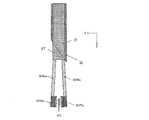
- FIG. 30 is a schematic cross-sectional view of the sensor holding bar 21 and the push bar 401 in the present embodiment cut along a plane parallel to the YZ plane (see FIG. 22).
- the sensor holding bar 21 in the present embodiment includes a hollow support bar 27, a pair of opening / closing bars 306, and a sensor fixing portion 305.
- the extrusion bar 401 has a cylindrical shape.
- the pair of opening / closing bars 306 includes a first opening / closing bar 306a (first connecting means) and a second opening / closing bar 306b (second connecting means).
- the sensor fixing unit 305 includes a first fixing unit 305a and a second fixing unit 305b.
- the sensing area of the sensor 40 is directed to the first fixed portion 305a side.
- the configuration of the support rod 27, the opening / closing rod 306, the sensor fixing portion 305, and the extrusion rod 401 when the sensor 40 having a 1 mm square and a thickness of 0.2 mm is embedded will be described.
- the size of the sensor 40, the configuration of the support rod 27, the opening / closing rod 306, the sensor fixing portion 305, and the push-out rod 401 are not limited to this example. The configuration can be changed as appropriate depending on the size of the sensor 40.
- L4 5 mm, for example.
- the support rod 27 has a cylindrical shape.
- a hole having a diameter of 0.5 mm is formed at the center of the support rod 27.
- the diameter of the support bar 27 is designed so that it can move without friction within the needle.
- the diameter of the support rod 27 is 1.65 mm, for example.
- one end of the opening / closing bar 306 is fixed within the circular side surface of the support bar 27.
- the distance (W) between the first open / close bar 306a and the second open / close bar 306b at the place where the support bar 27 and the open / close bar 306 are fixed is, for example, about 0.8 mm.
- a first angle (R7a) that is an angle formed by the surface of the first opening / closing bar 306a on the center side of the needle 32 and the center line B of the support bar 27 is, for example, about 3 degrees as a first initial angle It is comprised so that it may become.
- the second angle (R7b), which is an angle formed by the surface of the second opening / closing bar 306b on the center side of the needle 32 and the center line B of the support bar 27, is, for example, about 3 as the second initial angle. It is configured to be a degree.
- the value of the length L4, the first initial angle, and the second initial angle are not limited to specific values as long as the sensor 40 can be fixed and unlocked.
- the extrusion bar 401 has a cylindrical shape.
- the diameter of the extrusion bar 401 is, for example, 0.5 mm.
- the push bar 401 is inserted into the hole in the center of the support bar 27.
- FIG. 31 shows the sensor holding bar 21, the push bar 401, the needle 32, and the plane parallel to the YZ plane when the sensor holding bar 21 and the push bar 401 of this embodiment are installed in the needle hole 31. It is typical sectional drawing when the sensor 40 is cut
- the thickness of the needle 32 is, for example, 14G. That is, the inner diameter may be 1.69 mm and the outer diameter may be 2.11 mm.
- the cross section when the sensor fixing portion 305 in the present embodiment is cut along a plane parallel to the XY plane is substantially the same as the cross section shown in FIG. That is, the cross-sectional view shown in FIG. 18 may be substantially the same as the cross-sectional view taken along the line FF shown in FIG. Therefore, illustration is abbreviate
- the sensor fixing portion 305 (first fixing portion 305a, second fixing portion 305b) includes a recess 307 for avoiding contact with the sensor surface and a recess 308 into which the sensor 40 is fitted. ing.
- each of the first fixing portion 305a and the second fixing portion 305b has a semi-cylindrical shape.
- the radius of curvature (r3) of the sensor fixing portion 305 is about 0.8 mm
- the depth (T9) of the concave portion 307 is 0.2 mm
- the width (T10) of the concave portion 307 is 0.8 mm.
- the depth (T11) of the recess 308 is 0.1 mm
- the width (T12) of the recess 308 is 0.15 mm.
- the size and shape of the opening / closing bar 306 may be the same as in the sixth embodiment.
- the material of the opening / closing bar 306 and the sensor fixing portion 305 is not limited to a specific material as long as it is elastic and can be processed.
- Examples of the material of the sensor fixing portion 305 are metal, alloy, resin, and the like.
- processing methods for the support rod 27, the opening / closing rod 306, and the sensor fixing portion 305 include cutting and laser processing. As long as these materials can be processed, the processing method is not limited to a specific method.
- the width (S5) in the Z direction of the recesses 307 and 308 is, for example, 1.1 mm (see FIG. 30).
- the width (S6) in the Z direction of the sensor fixing portion 305 is, for example, 1.5 mm (see FIG. 30).
- the widths S5 and S6 are not limited to 1.1 mm and 1.5 mm, respectively.
- FIG. 32 is a schematic cross-sectional view of the sensor fixing portion 305 and the opening / closing bar 306 in a state outside the needle hole 31 of the needle 32 taken along a plane parallel to the YZ plane.
- the sensor fixing portion 305 and the opening / closing bar 306 come out of the needle hole 31, the distance between the opening / closing bars 306 (the distance between the first opening / closing bar 306a and the second opening / closing bar 306b) is maintained. Therefore, the sensor fixing portion 305 fixes the sensor 40 also outside the needle hole 31.
- FIG. 33 is a schematic cross-sectional view of the sensor fixing unit 305 and the open / close bar 306 cut along a plane parallel to the YZ plane in a state where the push bar 401 is pushed out.
- FIG. 33 shows a state after the push bar 401 is further pushed out toward the sensor fixing portion 305 from the state shown in FIG.
- the first fixing portion 305a is located on the side (for example, the surface side) where the sensing region of the sensor is located.
- fixed part 305b is located in the reverse side (for example, back side) where the sensing area
- the amount of change in the angle of the opening / closing bar 306 for releasing the fixation of the sensor 40 is relatively small. For this reason, extraction from the subject is easy, and damage to the subject can be reduced.
- FIG. 34 is a diagram illustrating an outline of a sensor embedding system 2000 according to still another exemplary embodiment of the present disclosure.
- the sensor embedding system 2000 embeds a sensor in a subject.
- the sensor embedding system 2000 includes a sensor and a sensor embedding device.
- the sensor includes a sensing area for detecting the state of the subject and a held portion.
- the sensor embedding device includes a needle 1100, a sensor holding unit 1200, and a movable part 1300.
- the sensor embedding device for example, the aforementioned sensor embedding device 1000 and sensor embedding device 1000A can be used.
- the sensor embedding device may be, for example, any of the sensor embedding devices according to the first to eighth embodiments.
- the sensor holding means 1200 may include a first fixing part and a second fixing part.
- the senor is held by holding the held portion of the sensor between the first fixing portion and the second fixing portion.
- the senor can be embedded in the subject with the sensing area facing a predetermined direction.
- the sensor can be embedded with the sensor surface on which the sensing region is located facing the skin surface of the living body.
- the sensor includes a held portion, and the held portion is sandwiched between the first fixing portion and the second fixing portion, so that the sensor holding means can hold the sensor with higher accuracy.
- a living body for example, a human body or an animal
- a living body for example, a human body or an animal
- a sensor chip 40c is exemplified as the sensor.
- a sensor embedding system including a sensor chip 40c structure and a sensor embedding device for embedding the sensor chip 40c when the surface-enhanced Raman scattering spectroscopy is applied as an optical technique will be described.
- the needle 32 in this embodiment includes a needle hole 31 through which the sensor chip 40c and the sensor holding bar 21 pass.
- FIG. 35 is a schematic top view showing an exemplary configuration of the sensor chip 40c.
- the sensor chip 40c includes a 1 mm square sensing region 41 on the upper surface.
- the sensor chip 40 c includes a 1 mm square held portion 42.
- a metal nanostructure for causing surface-enhanced Raman scattering due to localized surface plasmon resonance may be formed.
- a metal nanorod 43 (short axis size: about several nm to 100 nm, long axis size: about 50 to 500 nm) having a long axis oriented in the same direction is used as the metal nanostructure. May be.
- gold nanorods can exhibit two localized surface plasmon resonance bands. That is, localized surface plasmon resonance bands are shown in the vicinity of 520 nm derived from the minor axis direction of the rod and from 600 to 1500 nm derived from the major axis direction.
- the localized surface plasmon resonance wavelength is, for example, 700 to 1000 nm.
- gold nanorods having an average minor axis length of 10 nm and an average major axis length of 37 nm can be used.
- metal nanorods are used as metal nanostructures.
- the metal nanostructure may have a localized surface plasmon resonance wavelength of 700 to 1000 nm, and is not limited to a metal nanorod.
- metal nanodisks, metal spherical fine particles, metal lines, dielectric fine particles on which metal is laminated, and the like can be used.
- a known technique can be used without any particular limitation.
- a fine structure may be drawn by using X-ray lithography, electron beam lithography, or the like, and the fine structure may be produced by metal sputtering.
- a metal mold is fabricated on a Si substrate using X-ray lithography, electron beam lithography, etc.
- a nanostructure is fabricated on a resin using nanoimprinting technology, and then a metal nanostructure is fabricated by sputtering metal. May be.
- a metal nanostructure synthesized by a known technique such as a synthesis method using a chemical reaction or a synthesis method using a photoreaction may be fixed to a substrate.
- the metal nanostructure contains at least one selected from the group consisting of silver, gold, copper, aluminum and platinum.
- the held portion 42 can be a flat surface.
- the senor has a flat plate shape.
- the sensing region 41 may be a region formed on a part of the main surface of the sensor chip 40c.
- the held portion 42 may be a portion where the sensing region 41 is not formed in the sensor chip 40c.
- FIG. 36 is a schematic cross-sectional view of the sensor holding rod 21 in the present embodiment cut along a plane parallel to the YZ plane (see FIG. 1).
- the sensor holding bar 21 includes a support bar 27, a pair of opening / closing bars 26, and a sensor fixing portion 405.
- the sensor fixing unit 405 fixes the sensor chip 40c from above and below.
- the shape of the support bar 27 and the pair of opening / closing bars 26 in the present embodiment may be substantially the same as the shape of the support bar 27 and the pair of opening / closing bars 26 in the first embodiment. Therefore, below, description of the support bar 27 and the pair of opening / closing bars 26 is omitted.
- the sensor holding means includes a pair of opening / closing bars 26 and a sensor fixing portion 405.
- the sensor fixing unit 405 includes a first fixing unit 405a and a second fixing unit 405b.
- the sensor holding means holds the sensor by sandwiching the sensor between the first fixing portion and the second fixing portion.
- FIG. 37 is a schematic view when the sensor chip 40c, the sensor holding bar 21 and the needle 32 are cut along a plane parallel to the YZ plane when the sensor holding bar 21 of the present embodiment is installed in the needle hole 31. It is sectional drawing.
- the first fixing portion 405a is located on the side (for example, the surface side) where the sensing region of the sensor is located.
- fixed part 405b is located in the opposite side (for example, back surface side) to the side in which the sensing area
- the sensor chip 40c is fixed by sandwiching the held portion 42 by the sensor fixing portion 405.
- FIG. 38 is a schematic cross-sectional view (cross-sectional view taken along the line GG shown in FIG. 37) when the sensor fixing portion 405 is cut along a plane parallel to the XY plane.
- the sensor fixing portion 405 (the first fixing portion 405a and the second fixing portion 405b) includes a recess 408 into which the sensor chip 40c is fitted.
- each of the first fixing portion 405a and the second fixing portion 405b has a semi-cylindrical shape.
- the radius of curvature (r4) of the sensor fixing portion 405 is 0.8 mm
- the depth (T13) of the recess 408 is 0.1 mm
- the width (T14) of the recess 408 is 1 mm.
- the depth T13 and the width T14 have a plus tolerance with respect to 0.1 mm and 1 mm, respectively.
- the concave portion 408 is formed in the first fixing portion 405a and the second fixing portion 405b.
- the sensor is held by sandwiching the held portion of the sensor between the concave portion 408 of the first fixing portion 405a and the concave portion 408 of the second fixing portion 405b.
- the first fixing portion 405a and the second fixing portion 405b are semi-cylindrical as in the second and seventh embodiments.
- the number of corners in the sensor fixing unit 405 can be reduced as compared with a prism or the like. Therefore, it is possible to reduce damage to the subject (for example, living tissue) at the time of implantation.
- the material of the opening / closing rod 26 and the sensor fixing portion 405 is not limited to a specific material as long as it is elastic and can be processed.
- Examples of the material of the opening / closing rod 26 and the sensor fixing portion 405 are metals, alloys, resins, and the like.
- processing methods for the support rod 27, the opening / closing rod 26, and the sensor fixing portion 405 include cutting and laser processing. As long as these materials can be processed, the processing method is not limited to a specific method.
- the width (S7) in the Z direction of the recess 408 is, for example, 1.1 mm (see FIG. 36).
- the width (S8) in the Z direction of the sensor fixing portion 405 is, for example, 1.5 mm (see FIG. 36).
- the widths S7 and S8 are not limited to 1.1 mm and 1.5 mm, respectively.
- FIG. 39 is a schematic cross-sectional view of the sensor fixing portion 405 and the open / close bar 26 in a state outside the needle hole 31 of the needle 32, taken along a plane parallel to the YZ plane.
- the deformation is restored by the elasticity of the first opening / closing bar 26a and the second opening / closing bar 26b, The opening / closing bar 26 spreads out.
- the first angle R1a increases to the first initial angle (about 4 degrees).
- the second angle R1b increases to the second initial angle (about 4 degrees).
- the fixing of the sensor chip 40c by the sensor fixing unit 405 is released.
- the holding of the sensor is released.
- the operation when the sensor embedding device embeds the sensor chip 40c can be the same as the operation when the sensor embedding device 100 according to the first embodiment embeds the sensor 40 described with reference to FIGS. . Therefore, description of the operation when the sensor embedding device embeds the sensor chip 40c is omitted.
- the sensor embedding system includes a plunger, a needle guiding means, a cylinder into which the plunger is inserted, a contact portion, a needle extraction fixing means, and a sensor holding means extraction fixing.
- Means and embedding determination means may be provided.
- the plunger holds the needle, the movable part, and the sensor holding means.
- the needle guiding means holds the needle, the movable part, and the sensor holding means in a state where the needle, the movable part, and the sensor holding means are moved to a predetermined position by sliding the plunger.
- the contact portion is attached to the cylinder at a predetermined angle, has a hole through which the needle passes, and contacts the surface of the subject.
- the needle extraction fixing means fixes the needle extracted from the inside of the subject in the plunger.
- the sensor holding means pull-out fixing means fixes the movable part pulled out from the inside of the subject and the sensor holding means in the plunger.
- the embedding determination means notifies the user of the success or failure of embedding.
- the sensor embedding system may include an attaching means for attaching the contact portion to the surface of the subject.
- the first fixing portion 405a and the second fixing portion 405b have a semi-cylindrical shape.
- At least one of the first fixing portion 405a and the second fixing portion 405b may have a semi-cylindrical shape.
- the number of corners in the sensor fixing unit 405 can be reduced as compared with a prism or the like. Therefore, it is possible to reduce damage to the subject (for example, living tissue) at the time of implantation.
- the first fixing portion 405a and the second fixing portion 405b in a state where the sensor is held can be in contact with each other.
- the sensor chip 40c can be fixed more stably.
- the configuration of the sensing area 41 is not limited to a specific configuration. Instead of the metal nanostructure, fluorescence spectroscopy, absorption spectroscopy, reflection spectroscopy, or the like may be used by applying or fixing a fluorescent material, an absorbing material, or a reflecting material.
- the sensing region is The sensor may be embedded so that it faces away from the side where the needle is inserted.
- the sensor embedding apparatus may embed the sensor so that the sensing area faces the side that detects return light (for example, Raman scattered light, fluorescence) from the sensor.
- the sensor embedding system may embed the sensor so that the sensing region faces the side that detects return light (for example, Raman scattered light, fluorescence) from the sensor.
- only one of the first connecting means or the second connecting means is deformed and restored, so that the space between the first fixing portion and the second fixing portion is reduced.
- the distance may vary.
- only one of the first opening / closing bar (first connecting means) or the second opening / closing bar (second connecting means) is expanded by the pushing bar.
- the distance between the first fixing part and the second fixing part may change.
- first opening / closing bar first connecting means
- second opening / closing bar second connecting means
- the subject may be a human body or an animal.
- the subject may be inanimate.
- the presence or absence of the test substance in the subject may be detected as the state of the subject using a sensor.
- the concentration of the test substance in the subject may be measured as the state of the subject using a sensor.
- the test substance may be, for example, glucose, lactic acid, pyruvic acid, acetoacetic acid, 3-hydroxybutyric acid ( ⁇ -hydroxybutyric acid), and the like.
- the sensor shape is not limited to the chip shape (flat plate shape).
- the shape of the sensor may be any shape that can be held by the sensor holding means.
- the sensor may have a shape that can include a held portion.
- the sensor embedding device and the sensor embedding system according to the present disclosure are useful in an apparatus that measures or monitors a test substance (analyte) in a living body, for example, percutaneously using an optical technique. .
Abstract
La présente invention concerne un dispositif d'implantation de capteur qui permet d'implanter, dans un sujet, un capteur doté d'une région de détection permettant de détecter l'état dudit sujet, ledit dispositif comprenant les éléments suivants : une aiguille comportant un orifice et qui est insérée dans le sujet; un moyen de support de capteur permettant de maintenir le capteur de manière à ce que ce dernier soit implanté dans le sujet en orientant la région de détection dans une direction prédéfinie; et une pièce mobile permettant de déplacer le capteur dans le sujet en faisant glisser le moyen de support de capteur dans l'orifice mentionné ci-dessus.
Priority Applications (2)
| Application Number | Priority Date | Filing Date | Title |
|---|---|---|---|
| JP2015516918A JP5896322B2 (ja) | 2013-05-17 | 2014-05-14 | センサ埋込装置およびセンサ埋込システム |
| US14/941,007 US10194939B2 (en) | 2013-05-17 | 2015-11-13 | Sensor embedding device and sensor embedding system |
Applications Claiming Priority (6)
| Application Number | Priority Date | Filing Date | Title |
|---|---|---|---|
| JP2013-104710 | 2013-05-17 | ||
| JP2013-104708 | 2013-05-17 | ||
| JP2013104708 | 2013-05-17 | ||
| JP2013104709 | 2013-05-17 | ||
| JP2013-104709 | 2013-05-17 | ||
| JP2013104710 | 2013-05-17 |
Related Child Applications (1)
| Application Number | Title | Priority Date | Filing Date |
|---|---|---|---|
| US14/941,007 Continuation US10194939B2 (en) | 2013-05-17 | 2015-11-13 | Sensor embedding device and sensor embedding system |
Publications (1)
| Publication Number | Publication Date |
|---|---|
| WO2014185067A1 true WO2014185067A1 (fr) | 2014-11-20 |
Family
ID=51898056
Family Applications (1)
| Application Number | Title | Priority Date | Filing Date |
|---|---|---|---|
| PCT/JP2014/002534 WO2014185067A1 (fr) | 2013-05-17 | 2014-05-14 | Dispositif d'implantation de capteur et système d'implantation de capteur |
Country Status (3)
| Country | Link |
|---|---|
| US (1) | US10194939B2 (fr) |
| JP (1) | JP5896322B2 (fr) |
| WO (1) | WO2014185067A1 (fr) |
Cited By (2)
| Publication number | Priority date | Publication date | Assignee | Title |
|---|---|---|---|---|
| JP2016119948A (ja) * | 2014-12-24 | 2016-07-07 | アークレイ株式会社 | センサ挿入方法、分析方法およびセンサ挿入システム |
| WO2017130559A1 (fr) * | 2016-01-29 | 2017-08-03 | テルモ株式会社 | Dispositif de détection d'informations biologiques |
Families Citing this family (1)
| Publication number | Priority date | Publication date | Assignee | Title |
|---|---|---|---|---|
| US11730403B2 (en) | 2018-02-06 | 2023-08-22 | Arnold Chase | Diversified glucose sensor system |
Citations (3)
| Publication number | Priority date | Publication date | Assignee | Title |
|---|---|---|---|---|
| JP2009273610A (ja) * | 2008-05-14 | 2009-11-26 | Toshihiko Sato | 留置機能を備えたicタグ |
| JP2010000284A (ja) * | 2008-06-23 | 2010-01-07 | Toshihiko Sato | Icタグを用いた手術方法 |
| JP2012519833A (ja) * | 2010-04-20 | 2012-08-30 | パナソニック株式会社 | 生体に含有される生体成分の濃度を測定する方法 |
Family Cites Families (5)
| Publication number | Priority date | Publication date | Assignee | Title |
|---|---|---|---|---|
| US5620459A (en) * | 1992-04-15 | 1997-04-15 | Microsurge, Inc. | Surgical instrument |
| US5910148A (en) * | 1997-08-06 | 1999-06-08 | Mitek Surgical Products, Inc. | Suture retrograder |
| GB0025147D0 (en) | 2000-10-13 | 2000-11-29 | Torsana Diabetes Diagnostics A | Optical sensor for in situ measurement of analytes |
| GB0204640D0 (en) | 2002-02-27 | 2002-04-10 | Torsana Diabetes Diagnostics A | Injection apparatus |
| US7964390B2 (en) * | 2002-10-11 | 2011-06-21 | Case Western Reserve University | Sensor system |
-
2014
- 2014-05-14 JP JP2015516918A patent/JP5896322B2/ja not_active Expired - Fee Related
- 2014-05-14 WO PCT/JP2014/002534 patent/WO2014185067A1/fr active Application Filing
-
2015
- 2015-11-13 US US14/941,007 patent/US10194939B2/en active Active
Patent Citations (3)
| Publication number | Priority date | Publication date | Assignee | Title |
|---|---|---|---|---|
| JP2009273610A (ja) * | 2008-05-14 | 2009-11-26 | Toshihiko Sato | 留置機能を備えたicタグ |
| JP2010000284A (ja) * | 2008-06-23 | 2010-01-07 | Toshihiko Sato | Icタグを用いた手術方法 |
| JP2012519833A (ja) * | 2010-04-20 | 2012-08-30 | パナソニック株式会社 | 生体に含有される生体成分の濃度を測定する方法 |
Cited By (5)
| Publication number | Priority date | Publication date | Assignee | Title |
|---|---|---|---|---|
| JP2016119948A (ja) * | 2014-12-24 | 2016-07-07 | アークレイ株式会社 | センサ挿入方法、分析方法およびセンサ挿入システム |
| WO2017130559A1 (fr) * | 2016-01-29 | 2017-08-03 | テルモ株式会社 | Dispositif de détection d'informations biologiques |
| CN108366760A (zh) * | 2016-01-29 | 2018-08-03 | 泰尔茂株式会社 | 生物体信息检测装置 |
| JPWO2017130559A1 (ja) * | 2016-01-29 | 2018-11-22 | テルモ株式会社 | 生体情報検出装置 |
| US11026629B2 (en) | 2016-01-29 | 2021-06-08 | Terumo Kabushiki Kaisha | Biological information detection device |
Also Published As
| Publication number | Publication date |
|---|---|
| JPWO2014185067A1 (ja) | 2017-02-23 |
| US10194939B2 (en) | 2019-02-05 |
| US20160066953A1 (en) | 2016-03-10 |
| JP5896322B2 (ja) | 2016-03-30 |
Similar Documents
| Publication | Publication Date | Title |
|---|---|---|
| JP5896322B2 (ja) | センサ埋込装置およびセンサ埋込システム | |
| EP2468178B1 (fr) | Elément de test intégré destiné au prélèvement en une fois et à l'analyse d'un échantillon à analyser | |
| CN101283233B (zh) | 深度计 | |
| EP2704622B1 (fr) | Appareil d'irradiation de lumière, son procédé de commande et appareil d'acquisition d'informations d'objet | |
| EP1786325B1 (fr) | Lancette, ensemble lancette et combinaison lancette-capteur | |
| JP2010008493A (ja) | 対物レンズ用アダプタ | |
| JP2009519045A (ja) | 穿刺システム | |
| JP2009509646A5 (fr) | ||
| US10001442B2 (en) | Optical fiber-based hybrid SERS platform for in vivo detection of bio-molecules | |
| EP2859847A1 (fr) | Appareil de collecte de sang, lancette et dispositif autopiqueur | |
| EP2724665A2 (fr) | Appareil d'acquisition d'informations d'objet et couvercle pour sonde photoacoustique | |
| JP2006015143A (ja) | 一体形ランセットを含む医用器具のパッケージ化のための製造装置 | |
| WO2011037533A1 (fr) | Dispositif sers | |
| JP5834192B2 (ja) | 生体内における被検物質の濃度を計測する計測方法、および、計測装置 | |
| JP5024771B2 (ja) | 下地材探知具 | |
| JP2012519273A (ja) | センサカートリッジ用接続システム | |
| CN212160147U (zh) | 一种准直器及其保护管 | |
| JP2006201114A (ja) | 生体光計測装置 | |
| JP2015077336A (ja) | 生体用モニタリング装置 | |
| US20150354935A1 (en) | Tape scale application jig and tape scale application method | |
| JP5076035B1 (ja) | 生体に含有される生体成分の濃度を測定する方法 | |
| JP7313228B2 (ja) | 挿入装置 | |
| WO2019037143A1 (fr) | Dispositif et procédé de test de performance de retrait d'imagerie oct | |
| US20120302915A1 (en) | Spiral biopsy needle | |
| KR101813184B1 (ko) | 라만 분광용 탐침 및 그 제조방법 |
Legal Events
| Date | Code | Title | Description |
|---|---|---|---|
| 121 | Ep: the epo has been informed by wipo that ep was designated in this application |
Ref document number: 14797484 Country of ref document: EP Kind code of ref document: A1 |
|
| ENP | Entry into the national phase |
Ref document number: 2015516918 Country of ref document: JP Kind code of ref document: A |
|
| NENP | Non-entry into the national phase |
Ref country code: DE |
|
| 122 | Ep: pct application non-entry in european phase |
Ref document number: 14797484 Country of ref document: EP Kind code of ref document: A1 |