WO2014181860A1 - メタンと窒素の分離方法 - Google Patents
メタンと窒素の分離方法 Download PDFInfo
- Publication number
- WO2014181860A1 WO2014181860A1 PCT/JP2014/062450 JP2014062450W WO2014181860A1 WO 2014181860 A1 WO2014181860 A1 WO 2014181860A1 JP 2014062450 W JP2014062450 W JP 2014062450W WO 2014181860 A1 WO2014181860 A1 WO 2014181860A1
- Authority
- WO
- WIPO (PCT)
- Prior art keywords
- adsorption
- methane
- nitrogen
- pressure
- gas
- Prior art date
- Legal status (The legal status is an assumption and is not a legal conclusion. Google has not performed a legal analysis and makes no representation as to the accuracy of the status listed.)
- Ceased
Links
Images






Classifications
-
- B—PERFORMING OPERATIONS; TRANSPORTING
- B01—PHYSICAL OR CHEMICAL PROCESSES OR APPARATUS IN GENERAL
- B01D—SEPARATION
- B01D53/00—Separation of gases or vapours; Recovering vapours of volatile solvents from gases; Chemical or biological purification of waste gases, e.g. engine exhaust gases, smoke, fumes, flue gases, aerosols
- B01D53/02—Separation of gases or vapours; Recovering vapours of volatile solvents from gases; Chemical or biological purification of waste gases, e.g. engine exhaust gases, smoke, fumes, flue gases, aerosols by adsorption, e.g. preparative gas chromatography
- B01D53/04—Separation of gases or vapours; Recovering vapours of volatile solvents from gases; Chemical or biological purification of waste gases, e.g. engine exhaust gases, smoke, fumes, flue gases, aerosols by adsorption, e.g. preparative gas chromatography with stationary adsorbents
- B01D53/047—Pressure swing adsorption
-
- B—PERFORMING OPERATIONS; TRANSPORTING
- B01—PHYSICAL OR CHEMICAL PROCESSES OR APPARATUS IN GENERAL
- B01J—CHEMICAL OR PHYSICAL PROCESSES, e.g. CATALYSIS OR COLLOID CHEMISTRY; THEIR RELEVANT APPARATUS
- B01J20/00—Solid sorbent compositions or filter aid compositions; Sorbents for chromatography; Processes for preparing, regenerating or reactivating thereof
- B01J20/02—Solid sorbent compositions or filter aid compositions; Sorbents for chromatography; Processes for preparing, regenerating or reactivating thereof comprising inorganic material
- B01J20/20—Solid sorbent compositions or filter aid compositions; Sorbents for chromatography; Processes for preparing, regenerating or reactivating thereof comprising inorganic material comprising free carbon; comprising carbon obtained by carbonising processes
-
- B—PERFORMING OPERATIONS; TRANSPORTING
- B01—PHYSICAL OR CHEMICAL PROCESSES OR APPARATUS IN GENERAL
- B01J—CHEMICAL OR PHYSICAL PROCESSES, e.g. CATALYSIS OR COLLOID CHEMISTRY; THEIR RELEVANT APPARATUS
- B01J20/00—Solid sorbent compositions or filter aid compositions; Sorbents for chromatography; Processes for preparing, regenerating or reactivating thereof
- B01J20/28—Solid sorbent compositions or filter aid compositions; Sorbents for chromatography; Processes for preparing, regenerating or reactivating thereof characterised by their form or physical properties
- B01J20/28054—Solid sorbent compositions or filter aid compositions; Sorbents for chromatography; Processes for preparing, regenerating or reactivating thereof characterised by their form or physical properties characterised by their surface properties or porosity
- B01J20/28078—Pore diameter
- B01J20/28085—Pore diameter being more than 50 nm, i.e. macropores
-
- C—CHEMISTRY; METALLURGY
- C10—PETROLEUM, GAS OR COKE INDUSTRIES; TECHNICAL GASES CONTAINING CARBON MONOXIDE; FUELS; LUBRICANTS; PEAT
- C10L—FUELS NOT OTHERWISE PROVIDED FOR; NATURAL GAS; SYNTHETIC NATURAL GAS OBTAINED BY PROCESSES NOT COVERED BY SUBCLASSES C10G OR C10K; LIQUIFIED PETROLEUM GAS; USE OF ADDITIVES TO FUELS OR FIRES; FIRE-LIGHTERS
- C10L3/00—Gaseous fuels; Natural gas; Synthetic natural gas obtained by processes not covered by subclass C10G, C10K; Liquefied petroleum gas
- C10L3/06—Natural gas; Synthetic natural gas obtained by processes not covered by C10G, C10K3/02 or C10K3/04
- C10L3/10—Working-up natural gas or synthetic natural gas
- C10L3/101—Removal of contaminants
- C10L3/105—Removal of contaminants of nitrogen
-
- B—PERFORMING OPERATIONS; TRANSPORTING
- B01—PHYSICAL OR CHEMICAL PROCESSES OR APPARATUS IN GENERAL
- B01D—SEPARATION
- B01D2253/00—Adsorbents used in seperation treatment of gases and vapours
- B01D2253/10—Inorganic adsorbents
- B01D2253/102—Carbon
-
- B—PERFORMING OPERATIONS; TRANSPORTING
- B01—PHYSICAL OR CHEMICAL PROCESSES OR APPARATUS IN GENERAL
- B01D—SEPARATION
- B01D2253/00—Adsorbents used in seperation treatment of gases and vapours
- B01D2253/30—Physical properties of adsorbents
- B01D2253/302—Dimensions
- B01D2253/308—Pore size
-
- B—PERFORMING OPERATIONS; TRANSPORTING
- B01—PHYSICAL OR CHEMICAL PROCESSES OR APPARATUS IN GENERAL
- B01D—SEPARATION
- B01D2256/00—Main component in the product gas stream after treatment
- B01D2256/24—Hydrocarbons
- B01D2256/245—Methane
-
- B—PERFORMING OPERATIONS; TRANSPORTING
- B01—PHYSICAL OR CHEMICAL PROCESSES OR APPARATUS IN GENERAL
- B01D—SEPARATION
- B01D2257/00—Components to be removed
- B01D2257/10—Single element gases other than halogens
- B01D2257/102—Nitrogen
-
- B—PERFORMING OPERATIONS; TRANSPORTING
- B01—PHYSICAL OR CHEMICAL PROCESSES OR APPARATUS IN GENERAL
- B01D—SEPARATION
- B01D2259/00—Type of treatment
- B01D2259/40—Further details for adsorption processes and devices
- B01D2259/403—Further details for adsorption processes and devices using three beds
-
- C—CHEMISTRY; METALLURGY
- C10—PETROLEUM, GAS OR COKE INDUSTRIES; TECHNICAL GASES CONTAINING CARBON MONOXIDE; FUELS; LUBRICANTS; PEAT
- C10L—FUELS NOT OTHERWISE PROVIDED FOR; NATURAL GAS; SYNTHETIC NATURAL GAS OBTAINED BY PROCESSES NOT COVERED BY SUBCLASSES C10G OR C10K; LIQUIFIED PETROLEUM GAS; USE OF ADDITIVES TO FUELS OR FIRES; FIRE-LIGHTERS
- C10L2290/00—Fuel preparation or upgrading, processes or apparatus therefore, comprising specific process steps or apparatus units
- C10L2290/12—Regeneration of a solvent, catalyst, adsorbent or any other component used to treat or prepare a fuel
-
- C—CHEMISTRY; METALLURGY
- C10—PETROLEUM, GAS OR COKE INDUSTRIES; TECHNICAL GASES CONTAINING CARBON MONOXIDE; FUELS; LUBRICANTS; PEAT
- C10L—FUELS NOT OTHERWISE PROVIDED FOR; NATURAL GAS; SYNTHETIC NATURAL GAS OBTAINED BY PROCESSES NOT COVERED BY SUBCLASSES C10G OR C10K; LIQUIFIED PETROLEUM GAS; USE OF ADDITIVES TO FUELS OR FIRES; FIRE-LIGHTERS
- C10L2290/00—Fuel preparation or upgrading, processes or apparatus therefore, comprising specific process steps or apparatus units
- C10L2290/54—Specific separation steps for separating fractions, components or impurities during preparation or upgrading of a fuel
- C10L2290/542—Adsorption of impurities during preparation or upgrading of a fuel
Definitions
- the present invention relates to a method for separating methane and nitrogen.
- Natural gas is the energy source with the least amount of carbon dioxide emitted during combustion among fossil energy sources. For this reason, the amount of natural gas used has been increasing in recent years, but in Japan, LNG (liquefied natural gas) is imported from overseas gas fields.
- the process with relatively high greenhouse gas emissions is said to be an LNG liquefaction plant. Since methane has a warming potential 21 times that of carbon dioxide, minimizing the amount of methane in the exhaust gas generated from the LNG liquefaction plant is extremely effective in reducing greenhouse gas emissions.
- the composition of BOG varies depending on the production area where the gas field exists, but may contain a lot of nitrogen. In this case, since nitrogen has a boiling point significantly lower than that of methane, BOG will contain much more nitrogen than the stock solution. For example, the amount of nitrogen contained in BOG may be 20% to 60%. However, even if BOG contains a lot of nitrogen, most of it is methane, so if it is directly combusted and exhausted with a fryer or the like, the loss of methane increases and the impact on the environment is not small.
- BOG has been reliquefied and recovered using a refrigerant.
- methane and nitrogen are separated using a cryogenic separation method, and electricity is generated using methane as a fuel for a gas engine or the like.
- Patent Documents 1 and 2 describe a method for obtaining high-purity nitrogen gas and methane with a high recovery rate. Is not listed.
- JP 2011-201969 A Japanese Patent No. 2579179
- the cryogenic separation method has a problem that the equipment cost is expensive.
- the cryogenic separation method is suitable for a relatively large amount of processing, it is suitable for small and medium-sized gas fields, specifically a small BOG flow rate of several thousand to several tens of thousands Nm 3 / h.
- the present situation is that there is no separation method of methane and nitrogen that is not suitable for LNG facilities and suitable for these LNG facilities.
- the LNG facility is a facility that handles flammable gas, a large amount of nitrogen is used for facility sealing for safety purposes. Nitrogen used for such applications is a seal intended to prevent explosion of methane, so a concentration of 95% or more is sufficient.
- Nitrogen can be obtained with a high purity by using a cryogenic separation method when separating BOG.
- a cryogenic separation method when separating BOG.
- it is suitable for large-sized LNG equipment, and is therefore suitable for medium-sized LNG equipment.
- the equipment cost was too expensive.
- the present invention has been made in consideration of such circumstances, and the object thereof is, for example, a high-purity nitrogen gas from a mixed gas of methane and nitrogen such as BOG generated in an LNG facility by using an inexpensive apparatus. And providing a method for recovering methane for power generation at a high recovery rate.
- the present invention employs the following configuration.
- a carbonaceous adsorbent having a benzene adsorption amount of 10 to 40 wt% is used as the gas separation adsorbent, and the pressure equalizing step time is 7 seconds to 35 seconds
- the adsorbent for gas separation has an adsorption amount of benzene of 10 to 40 wt%, an adsorption amount of methane of 1.7 to 2.4 mol / kg, an average diameter of macropores of 1 ⁇ m or less, and a diameter of The method for separating methane and nitrogen according to (1), wherein the adsorbent is an activated carbon-based adsorbent molded into a pellet of 2 mm or less.
- a gas separation adsorbent for separating methane and nitrogen by a pressure fluctuation type adsorption method wherein the adsorption amount of benzene is 10 to 40 wt%, and the adsorption amount of methane is 1.7 to 2.4 mol /
- An adsorbent for gas separation wherein the adsorbent is an activated carbon-based adsorbent formed into pellets having an average diameter of kg and macropores of 1 ⁇ m or less and a diameter of 2 mm or less.
- methane is obtained at a recovery rate of 95% or more from a mixed gas of methane and nitrogen such as BOG, for example, while using an inexpensive PSA apparatus, and a concentration of 95 % Or more of nitrogen can be obtained.
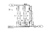
- FIG. 1 is a system diagram showing an outline of a separation apparatus for methane and nitrogen according to the first embodiment of the present invention.
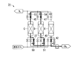
- FIG. 2 is a system diagram showing an outline of a separation apparatus for methane and nitrogen according to the second embodiment of the present invention.
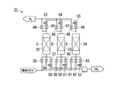
- FIG. 3A is a system diagram showing a process of the method for separating methane and nitrogen according to the second embodiment of the present invention.
- FIG. 3B is a system diagram showing a process of the method for separating methane and nitrogen according to the second embodiment of the present invention.
- FIG. 3C is a system diagram showing a process of the method for separating methane and nitrogen according to the second embodiment of the present invention.
- FIG. 3A is a system diagram showing a process of the method for separating methane and nitrogen according to the second embodiment of the present invention.
- FIG. 3B is a system diagram showing a process of the method for separating methane and nitrogen according to the second embodiment of the present invention.
- FIG. 3C is
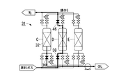
- FIG. 4A is a system diagram showing a process of the method for separating methane and nitrogen according to the second embodiment of the present invention.
- FIG. 4B is a system diagram showing a process of the method for separating methane and nitrogen according to the second embodiment of the present invention.
- FIG. 4C is a system diagram showing a process of the method for separating methane and nitrogen according to the second embodiment of the present invention.
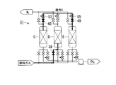
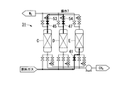
- FIG. 5A is a system diagram showing a process of the method for separating methane and nitrogen according to the second embodiment of the present invention.
- FIG. 5B is a system diagram showing a process of the method for separating methane and nitrogen according to the second embodiment of the present invention.
- FIG. 5A is a system diagram showing a process of the method for separating methane and nitrogen according to the second embodiment of the present invention.
- FIG. 5B is a system diagram showing a process of the method for separating methane and nitrogen according to the second embodiment of the present invention.
- FIG. 5C is a system diagram showing a process of the method for separating methane and nitrogen according to the second embodiment of the present invention.
- FIG. 6 is a system diagram showing a process of the method for separating methane and nitrogen according to the second embodiment of the present invention.
- FIG. 7 is a system diagram showing an outline of a methane / nitrogen separation apparatus used in the first embodiment of the present invention.
- FIG. 1 is a system diagram showing an outline of a separation apparatus 1 for separating methane and nitrogen.
- the separation apparatus 1 of the present embodiment is a PSA separation apparatus suitable for performing a PSA separation method (pressure fluctuation type adsorption method).
- the separation device 1 measures the adsorption towers A and B of the two towers, the MFC (mass flow controller) 4 that adjusts the flow rate of the supplied raw material gas, the MFC 5 that adjusts the flow rate of nitrogen to be taken out, and the pressure of the supplied raw material gas
- a pressure gauge 6 that measures the pressure of nitrogen to be taken out
- pressure gauges 8 and 9 that measure the pressure in the adsorption towers A and B
- a blower 10 that exhausts the methane in the adsorption towers A and B
- On-off valves 11 to 18 for switching the adsorption towers A and B to a pressurization process, an adsorption process, a pressure equalization process, and an exhaust process (regeneration process), and a pipe (equalization) for communicating both adsorption towers A and B in the pressure equalization process
- a flow rate adjusting valve 20 provided in the pressure line 19.
- Adsorption towers A and B are filled with gas separation adsorbents 21 and 22 made of the same material, and these gas separation adsorbents 21 and 22 have a larger amount of equilibrium adsorption of methane than nitrogen. It has the characteristic. Therefore, the gas separation adsorbents 21 and 22 are adsorbents that preferentially adsorb methane over nitrogen.
- adsorbents 21 and 22 for gas separation can be used.
- Activated carbon, zeolite, or the like having a N of 20 Ncc / g or more can be used.
- Such activated carbon is, for example, a carbonaceous material obtained by pulverizing coconut husk or coconut husk charcoal that has been completely carbonized in nitrogen gas at 600 ° C. to a particle size of 1 to 3 mm, and using an activation furnace. Thus, it can be obtained by activation at 800 to 860 ° C. in an atmosphere of 10 to 15 vol% of water vapor and 15 to 20 vol% of carbon dioxide mainly containing nitrogen.
- a carbonaceous adsorbent having an adsorption amount of benzene of 10 to 40 wt% as another adsorbent for gas separation in which methane is larger in the equilibrium adsorption amount than nitrogen.
- the methane adsorption amount is 1.7 to 2.4 mol / kg
- the average diameter (Medium diameter) of the macropores derived from the primary particle diameter is 1 ⁇ m or less, which is formed into a pellet shape having a diameter of 2 mm or less. It is preferable to use a molded activated carbon-based adsorbent.
- Such an adsorbent is obtained by, for example, crushing coconut shell or coconut shell charcoal in a nitrogen gas at 600 ° C. to a particle size of 1 to 10 ⁇ m, adding a binder to this, and granulating it.
- the separation method of the present embodiment is one in which the pressurization step, the adsorption step, the pressure equalization step, and the exhaust step are alternately performed with time in the adsorption towers A and B. Specifically, the process as shown in Table 1 is performed. Done in In addition, in the following description, it demonstrates using the process name currently performed with the adsorption tower A. FIG.
- the pressurizing step is a step of supplying a raw material gas (raw material air) compressed by a compressor (not shown) to the adsorption tower A and increasing the pressure inside the adsorption tower A to about 0.2 MPaG, for example. At this time, in the adsorption tower B, an exhaust process described later is performed.
- the on-off valves 11 and 14 are open and the other on-off valves are closed, so that the source gas is introduced from the inlet side of the adsorption tower A through the on-off valve 11.
- the source gas a mixed gas mainly composed of methane and nitrogen is used.
- ⁇ Adsorption process> After the pressure in the adsorption tower A is increased to a predetermined pressure by the pressurization process, the process proceeds to the adsorption process.
- the adsorption step as in the pressurization step, the raw material gas compressed by a compressor (not shown) is supplied to the adsorption tower A to maintain the pressure in the adsorption tower A at a predetermined pressure, and nitrogen is supplied from the adsorption tower A. It is a process of taking out. At this time, in the adsorption tower B, an exhaust process described later is continuously performed.
- the source gas is introduced only into the adsorption tower A as in the pressurization process.
- the nitrogen concentration increases from the inlet side to the outlet side in the adsorption tower A, and the gas taken out from the outlet side of the adsorption tower A is For example, the concentration of nitrogen is 95% or more.
- the extracted nitrogen is led out to the outside after the flow rate is adjusted by the MFC 5.
- the pressure equalization step is a step of moving the gas in the adsorption tower A by communicating the adsorption tower A after the adsorption process and the adsorption tower B after the exhaust process. That is, the pressure equalization process is a process in which the adsorption tower B whose pressure in the adsorption tower A increased in the adsorption process is reduced to, for example, about atmospheric pressure by the exhaust process is recovered.
- the on-off valves 15 and 16 are open, and the other on-off valves are closed, so that the gas in the adsorption tower A pressurized by the adsorption step passes through the pressure equalization line 19 and is exhausted. It introduce
- the gas that migrates in this pressure equalization step may be referred to as a pressure equalization gas.
- the time of the pressure equalization process is controlled to 25 seconds or more and 35 seconds or less.
- the pressure in the adsorption tower B rises, but by controlling the time of the pressure equalization step to 25 seconds or more, a rapid pressure increase can be prevented. Thereby, for example, high-purity nitrogen having a concentration of 95% or more can be obtained.
- buffer tanks not shown on the inlet side and the outlet side of the adsorption towers A and B There is an inconvenience that it must be increased. Therefore, it is preferable to control the time of the pressure equalizing step to 35 seconds or less.
- the lower limit of the pressure equalization process time can be set to 7 seconds or more.
- the pressure equalization process it is preferable to control so that the pressure change in the adsorption tower B is gradually performed from the beginning to the end of the pressure equalization process.
- the pressure change in the adsorption tower B is adjusted to 100 kPa / sec or less by adjusting the flow rate of the pressure equalizing gas as appropriate using the flow rate adjusting valve 20 in the pressure equalizing line 19. It is preferable to set it as sec or less. By adjusting in this way, a sudden pressure increase in the adsorption tower B can be prevented.
- the nitrogen component in the adsorption tower A can be preferentially used as the pressure equalizing gas by slowly flowing the pressure equalizing gas, and the concentration and recovery rate of nitrogen to be taken out can be improved.
- the flow rate of the pressure equalized gas is appropriately adjusted by feeding back the pressure values in the adsorption towers A and B.
- the values of the pressure gauges 8 and 9 are periodically transmitted to a control unit (not shown), and after appropriate calculation processing based on these values, the control unit applies to the flow rate adjustment valve 20. It is preferable to adjust so as to indicate the opening degree.
- the pressure equalizing line 19 is provided on the outlet side (upper side) of the adsorption towers A and B has been described, but it may be provided on the inlet side (lower side) of the adsorption towers A and B. However, it may be provided on both the inlet side and the outlet side.
- the exhaust process is a process of reducing the pressure in the adsorption tower A to, for example, about atmospheric pressure, desorbing methane adsorbed on the gas separation adsorbent 21, and regenerating the gas separation adsorbent 21.
- a pressurizing step and a subsequent adsorption step are performed.
- the open / close valves 12 and 13 are open (the open / close valve 18 is also open when the adsorption tower B is in the adsorption process), and the other open / close valves are closed.
- the methane adhering to the gas separation adsorbent 21 is desorbed and scavenged. This process recovers methane.
- the concentration of recovered methane is, for example, 70% or more, and the recovery rate of methane is, for example, 95% or more.
- a PSA apparatus pressure fluctuation type adsorption apparatus
- the equipment cost can be greatly reduced as compared with the case where the cryogenic separator is employed.
- the pressure equalizing step time is set to 25 seconds or more and 35 seconds or less, for example, high-purity nitrogen having a concentration of 95% or more can be recovered. As a result, there is no need to purify the nitrogen concentration with high purity at the latter stage of the present PSA apparatus, and the economic effect is extremely large.
- the pressure change in the adsorption towers A and B can be gradually performed by appropriately adjusting the flow rate of the pressure equalization gas in the pressure equalization line 19 using the flow rate adjusting valve 20, and the adsorption tower A sudden pressure rise in A and B can be prevented. Thereby, nitrogen can be obtained more appropriately.
- the flow rate of the pressure equalizing gas is adjusted appropriately by feeding back the pressure values in the adsorption towers A and B, so that the pressure change can be gradually made. , B can be further prevented from suddenly increasing pressure. Thereby, nitrogen can be obtained more appropriately.
- FIG. 2 is a system diagram showing an outline of a separation apparatus for separating methane and nitrogen according to the present embodiment.
- FIGS. 3A to 5C are system diagrams for explaining a process of the method for separating methane and nitrogen according to the present embodiment. is there.
- FIG. 2 it differs from the first embodiment in that three adsorption towers are provided.
- the same parts as those in the first embodiment will be omitted as appropriate, and in FIGS. 2 to 5A to C, the MFC, blower, etc. are omitted.
- the separation device 31 of the present embodiment has three adsorption towers C, D, and E, and these three adsorption towers C, D, and E all have the same material as the adsorbent 32 for gas separation. , 33 and 34 are filled. As in the first embodiment, the gas separation adsorbents 32, 33, and 34 have a characteristic that the amount of equilibrium adsorption is larger for methane than for nitrogen.
- the separation device 31 is provided with on-off valves 35 to 49, and by controlling these on-off valves 35 to 49, the adsorption towers C, D, and E are connected to the pressurizing step, the adsorbing step, and the first equalizing step. The pressure process, the second pressure equalization process, the exhaust process, and the standby process are switched. Further, the separation device 31 is provided with flow rate adjusting valves 50 to 55.
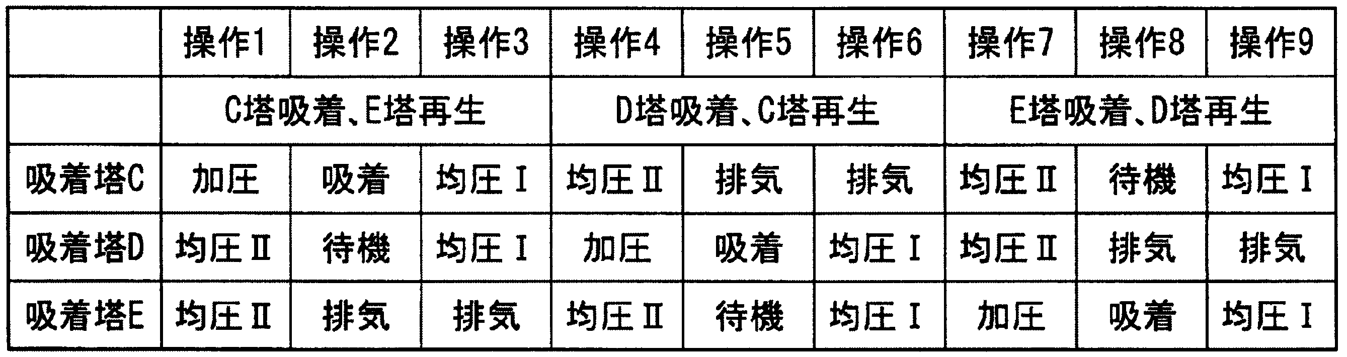
- the separation method of the present embodiment includes a pressurization process, an adsorption process, a first pressure equalization process, a second pressure equalization process, an exhaust process, a second pressure equalization process, a standby process, a first process in each of the adsorption towers C, D, and E.
- the pressure equalization process is performed in this order, but the timing of performing these processes is different in each of the adsorption towers C, D, and E. Specifically, the processes are shown in Table 2. Yes.
- FIG. 1 the first pressure equalization step is described as “pressure equalization I”, and the second pressure equalization step is described as “pressure equalization II”. Also, in FIGS. 3A to 5C, the black on-off valve is open, the white on-off valve is closed, and the piping through which the gas flows is shown thicker with an arrow attached.
- the pressurizing step (operation 1) is a step of increasing the pressure in the adsorption tower C by supplying the compressed source gas to the adsorption tower C, as in the first embodiment. At this time, in the adsorption towers D and E, a second pressure equalizing step described later is performed. Therefore, since the second pressure equalization process is performed in the adsorption towers D and E, the time of this process is controlled to 25 seconds or more and 35 seconds or less.
- the pressure change in the adsorption tower D is controlled by controlling the flow rate adjusting valves 54 and 55 provided in the piping (equal pressure equalization line) through which the pressure equalizing gas moving from the adsorption tower E to the adsorption tower D passes. It is preferable to control so that it is performed gradually from the beginning to the end.
- the pressurized source gas is supplied to the adsorption tower C to maintain the pressure in the adsorption tower C at a predetermined pressure and, for example, a high purity having a concentration of 95% or more.
- This is a step of taking out the nitrogen gas from the adsorption tower C.
- a standby process described later is performed in the adsorption tower D, and an exhaust process described later is performed in the adsorption tower E.
- the open / close valves 35, 42, and 44 are open, and the other open / close valves are closed.
- the first pressure equalization step is a step of recovering the pressure in the adsorption tower C after the adsorption step is completed by the adsorption tower D whose pressure has been increased to a certain degree through the second pressure equalization step.
- the exhaust process described later is continuously performed.
- the open / close valves 42, 45, 47 are open, and the other open / close valves are closed.
- This first pressure equalization step is controlled to be performed for 25 seconds or more and 35 seconds or less, similarly to the pressure equalization step of the first embodiment. Further, by controlling the flow rate adjusting valves 53 and 54 provided in the piping (equal pressure equalization line) through which the pressure equalizing gas moving from the adsorption tower C to the adsorption tower D passes, the pressure change in the adsorption tower D is changed to the first equalization pressure. It is preferable to control so that it is performed gradually from the beginning to the end of the pressing step.
- the adsorption tower C after the completion of the first pressure equalization process and the adsorption tower E after the completion of the exhaust process are communicated to move the gas in the adsorption tower C to the adsorption tower E, thereby increasing the pressure. Is a step of recovering.
- the adsorption tower E which has been reduced in pressure to the atmospheric pressure, for example, about atmospheric pressure by the exhaust step, is recovered by using the exhaust pressure step. It is a process.
- a pressurizing step is performed in the adsorption tower D.
- the on-off valves 38, 45, and 49 are open, and the other on-off valves are closed.
- This second pressure equalization step is controlled to be performed for 25 seconds or more and 35 seconds or less, similarly to the pressure equalization step of the first embodiment.
- the pressure change in the adsorption tower E is controlled by controlling the flow rate adjusting valves 53 and 55 provided in the piping (equal pressure equalization line) through which the pressure equalizing gas moving from the adsorption tower C to the adsorption tower E passes. It is preferable to control so that it is performed gradually from the beginning to the end.
- the process proceeds to the exhaust process (operation 5).
- the pressure in the adsorption tower C is reduced to, for example, about atmospheric pressure to desorb methane adsorbed on the gas separation adsorbent 32, and the gas separation adsorption is performed.
- the agent 32 is regenerated.
- an adsorption process is performed in the adsorption tower D, and a standby process described later is performed in the adsorption tower E.
- the concentration of methane recovered in this step is, for example, 70% or more, and the methane recovery rate is, for example, 95% or more.
- the on-off valves 36, 38, 46 are open, and the other on-off valves are closed.
- the open / close valves 36, 47, and 49 are open, and the other open / close valves are closed. Further, by controlling the flow rate adjusting valves 54 and 55 provided in the pipe (equal pressure equalization line) through which the pressure equalizing gas moving from the adsorption tower D to the adsorption tower E passes, the pressure change in the adsorption tower E can be reduced in the exhaust process. It is preferable to control to be constant from the beginning to the end.
- ⁇ Second pressure equalizing step (operation 7)> After the exhaust process is completed, the process proceeds to the second pressure equalization process (operation 7).
- the gas in the adsorption tower D is moved to the adsorption tower C by communicating the adsorption tower C after the exhaust process and the adsorption tower D after the completion of the first pressure equalization process. . That is, in the second pressure equalization process, the adsorption tower C that has been reduced to, for example, about atmospheric pressure by the exhaust process recovers the pressure from the adsorption tower D that has undergone the first pressure equalization process.
- a pressurizing process is performed in the adsorption tower E.
- the on-off valves 41, 45, 47 are open, and the other on-off valves are closed.
- the time for the second pressure equalizing step is controlled to be 25 seconds or more and 35 seconds or less.
- the flow rate adjusting valves 53 and 54 provided in the pipe (equal pressure equalization line) through which the pressure equalizing gas moving from the adsorption tower D to the adsorption tower C passes, the pressure change in the adsorption tower C is changed to the second equalization pressure. It is preferable to control so that it is performed gradually from the beginning to the end of the pressing step.
- first pressure equalizing step (operation 9)> After the standby process is completed, the process proceeds to the first pressure equalization process (operation 9).
- the adsorption tower C after performing the standby step through the second pressure equalization step and the adsorption tower E after the completion of the adsorption step are communicated with each other so that the gas in the adsorption tower E is removed. It is a process of moving into C. That is, this step is a step of recovering the pressure in the adsorption tower E after completion of the adsorption step by the adsorption tower C whose pressure has been increased to a certain degree through the second pressure equalization step.
- an exhaust process is performed in the adsorption tower D.
- the open / close valves 39, 45, and 49 are open, and the other open / close valves are closed.
- the time for the first pressure equalizing step is controlled to be 25 seconds or more and 35 seconds or less. Further, by controlling the flow rate adjusting valves 53 and 55 provided in the pipe (equal pressure equalization line) through which the pressure equalizing gas moving from the adsorption tower E to the adsorption tower C passes, the pressure change in the adsorption tower C is changed to the first equalization pressure. It is preferable to control so that it is performed gradually from the beginning to the end of the pressing step. After the end of the first pressure equalizing process, the process proceeds to the pressurizing process (operation 1), and the above processes are repeated thereafter.
- the separation of methane and nitrogen is performed by the PSA apparatus, so that the equipment cost can be greatly reduced compared to the case where the cryogenic separation apparatus is employed. it can. Moreover, since the time of the pressure equalization process is set to 25 seconds or more and 35 seconds or less, high-purity nitrogen can be recovered.
- the pressure in the adsorption tower after the adsorption process is recovered in two stages of the first pressure equalization process and the second pressure equalization process, it is two thirds of the pressure in the adsorption tower after the adsorption process.
- the pressure can be recovered. This makes it possible to recover two-thirds of the nitrogen remaining in the adsorption tower after the adsorption process.
- control is performed so that the pressure change in the pressure equalization process is gradually performed from the beginning to the end of the pressure equalization process by using the flow rate adjusting valves 50 to 55. It is preferable to feed back the pressure value of the adsorption tower during the pressure equalization step and control the flow rate adjusting valves 50 to 55.
- the pressure equalizing line is provided on the outlet side (upper side) of the adsorption towers C to E has been described, but it may be provided on the inlet side (lower side) of the adsorption towers C to E. These may be provided on both the inlet side and the outlet side.
- the pressure equalizing gas moving from the adsorption tower C to the adsorption tower D is adsorbed by opening the on-off valves 37, 40, 45, 47. Both the pressure equalization line on the inlet side of the towers C and D and the pressure equalization line on the outlet side can be passed.
- the pressure change in the adsorption tower D is gradually increased from the beginning to the end of the first pressure equalizing step. It is preferable to control to be performed.
- Example 1 methane and nitrogen were separated using a separation device substantially similar to the separation device shown in FIG. However, unlike the separation apparatus of FIG. 1, in this embodiment, as shown in FIG. 7, instead of a mixed gas in which methane and nitrogen are mixed in advance, methane and nitrogen are supplied from separate sources. It was adopted.
- the PSA apparatus was formed by using two columns with 200 ml capacity, which is filled with activated carbon having a higher methane adsorption capacity, that is, the equilibrium adsorption amount of methane is larger than that of nitrogen.
- a source gas a mixed gas of 55% methane + 45% nitrogen was supplied at 1 L / min.
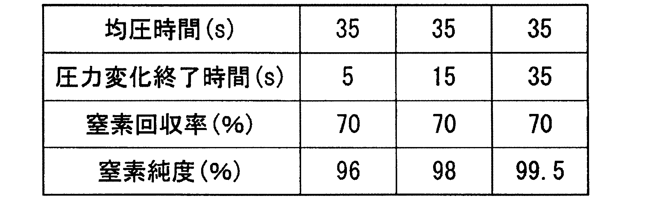
- Example 2 Next, an experiment was performed under the same experimental conditions as in Example 1, with the pressure equalization time being 35 seconds, and changing the time at which the pressure change of the adsorption tower during the pressure equalization time was completed. That is, although the pressure equalizing step time is 35 seconds, methane and nitrogen were separated by controlling the pressure equalizing gas flow rate so that the time when the pressure change was completed was 3, 15, and 35 seconds, respectively.
- Table 4 shows the relationship between the nitrogen concentration and the pressure equalizing time when the pressure change end time and the recovery rate of the nitrogen gas obtained as the non-adsorbed gas are 70%.
- Example 3 methane and nitrogen were simultaneously separated by the process shown in Table 2 using the separation apparatus shown in FIG. 2 using three columns of 1.4 L capacity packed with activated carbon having a low methane adsorption capacity. Further, a mixed gas of 55% methane + 45% nitrogen was supplied at 6 L / min as a source gas.
- the nitrogen concentration can be increased to 99% or more if the three-column system is used.
- the pressure equalization time during which the nitrogen concentration was high was 25 to 35 seconds, which was the same as the results of Examples 1 and 2.
- Example 1 As a comparative example of Example 3, a separation experiment of methane and nitrogen was performed using activated carbon having a low methane adsorption capacity and two columns. The conditions other than the number of adsorption towers were the same as in Example 3, and the pressure equalization time was 35 seconds. The results are listed in the last column of Table 5. From this result, it can be seen that the activated carbon with low performance has a nitrogen concentration of only 80% in the 2-tower type, but the performance can be greatly improved by using the 3-tower type, and a nitrogen concentration of 99% or more can be obtained. .
- Example 4 methane and nitrogen were separated from the adsorbent produced in-house using the apparatus shown in FIG.
- the adsorbent used was obtained by pulverizing palm shell char to about 5 ⁇ m with a vibration mill (manufactured by Chuo Kogyo Co., Ltd.), adding a binder and granulating it to form a pellet having a diameter of 1.4 mm. This was subjected to activation treatment at 850 ° C. in a 10 to 15 wt% steam atmosphere, and five types of sample samples A to E having different activation levels were produced by changing the treatment time.
- the benzene adsorption amount was measured according to JIS K1474.
- the amount of benzene adsorbed was 7 to 38 wt%.
- the greater the degree of activation the greater the amount of benzene adsorption.
- the methane adsorption amount was measured with a volumetric adsorption amount measurement device (BELSORP-HP-30, manufactured by Nippon Bell Co., Ltd.). About 1 g of a sample is taken, and after an accurate weight is measured, it is placed in a cell with a known capacity. Methane gas is introduced into the gas tank whose capacity has been measured in advance, and the pressure is recorded.
- the cell containing the sample and the gas tank are connected, and the state is maintained until the pressure is balanced. Calculate the amount of methane adsorbed from the equilibrium pressure.
- the operating conditions of the PSA were a column switching time of 240 seconds and a pressure equalization time of 25 seconds.
- the raw material gas was supplied so that the ratio of methane to nitrogen was 55:45, the amount of product nitrogen was adjusted so that the methane concentration was 80%, and the nitrogen concentration and methane recovery rate at that time were measured.
- Table 6 shows the benzene adsorption amount of each sample, the methane adsorption amount at 200 kPaG, and the average diameter of the macropores.
- Macropores originate from the gaps between the primary particles and are proportional to the primary particle size.
- the average diameter of the macropores was a value obtained by measuring the pore size distribution up to 0.01 ⁇ m by the mercury intrusion method, and a mercury porosimeter (Pore Master GT) manufactured by Cantachrome was used for the measurement.
- a mercury porosimeter Pane Master GT
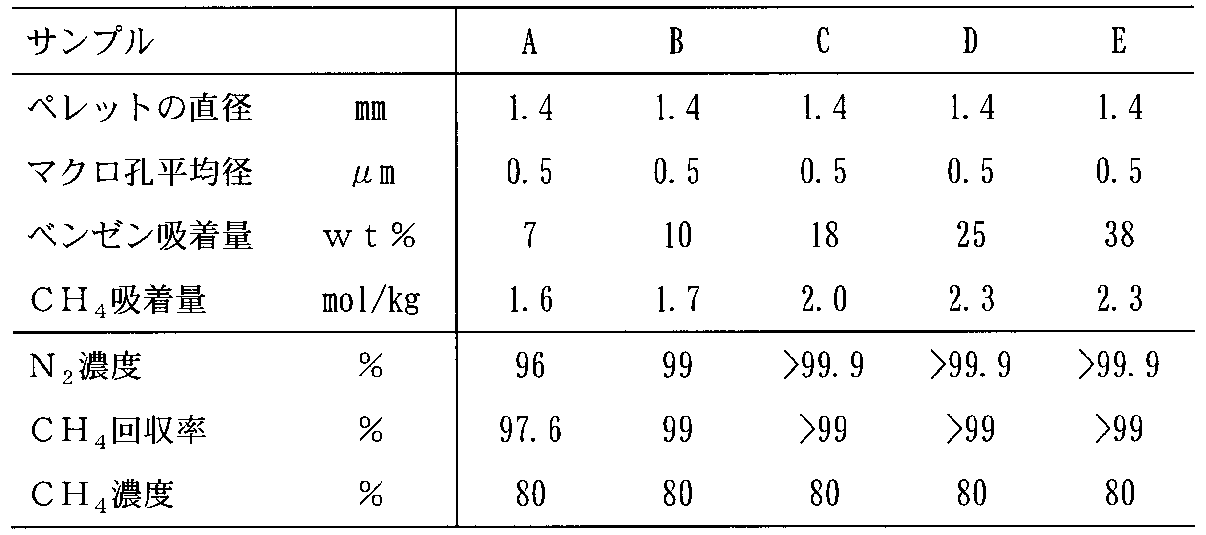
- methane with a concentration of 80% was recovered in a yield of 99% or more, and 99% or more Of nitrogen could be separated and recovered.
- the sample A having a benzene adsorption amount of 7 wt% neither the nitrogen concentration 99% nor the methane recovery rate 99% can be achieved.
- Example 2 molecular sieve activated carbon (MSC), crushed activated carbon (AC-1) and granular activated carbon (AC-2) were used to separate methane and nitrogen.
- MSC molecular sieve activated carbon
- AC-1 crushed activated carbon
- AC-2 granular activated carbon
- Example 5 coconut shell charcoal was pulverized to about 8 ⁇ m and then granulated into pellets having a diameter of 2 mm. Similarly to sample D, the activation treatment was performed by adjusting the conditions so that the benzene adsorption amount was 25 wt%, and sample F was obtained. In Comparative Example 3, coconut husk charcoal was pulverized to about 20 ⁇ m, then added with a binder, granulated, and molded into a 4 mm diameter pellet. Similarly to Samples D and F, activation conditions were adjusted so that the benzene adsorption amount was 25 wt%, and Sample G was obtained. As in Example 4, methane and nitrogen were separated using the apparatus shown in FIG. Table 8 shows the results of benzene adsorption amount, methane adsorption amount at 200 kPaG, pellet diameter and macropore average diameter.
- Samples F and G have almost the same benzene adsorption amount and methane adsorption amount, but have a great difference in the separation performance of methane and nitrogen. Since activated carbon is an equilibrium separation agent, the influence of pellet diameter on performance is small under the conditions normally used, and the influence of pressure loss in the adsorption tower is larger. Therefore, a pellet-shaped adsorbent having a diameter of about 4 mm is generally used so as to reduce the pressure loss.
- the MSC which is a speed separation type generally has a pellet diameter of 2 mm or less because the diffusion of gas in the pellet greatly affects the performance. Separation of methane and nitrogen is equilibrium adsorption separation, and from the common sense so far, the influence of pellet diameter on performance should be small. It was found that an adsorbent having a smaller primary particle size shows higher separation performance.
- Example 6 and Comparative Example 4 Comparison of pressure equalization process time Using the sample D, the column switching time was changed to 4 minutes, and the pressure equalization time was changed from 5 to 40 seconds. Evaluation was performed. At this time, the pressure equalization gas flow rate was controlled by a flow rate control valve installed in the pressure equalization line so that the pressure equalization was completed at the end of the pressure equalization time. Table 9 shows the nitrogen concentration and the methane recovery rate when product nitrogen was taken out so that the methane concentration became 80%.
- Example 7 (Example 7 and Comparative Example 5)
- Sample B the separation performance of methane and nitrogen was examined with a column switching time of 4 minutes and a pressure equalization time of 25 seconds.
- the equalized gas flow rate was controlled by a flow rate adjusting valve installed in the pressure equalizing line so that the time during which the pressures of the adsorption towers A and B were the same was 5 to 25 seconds.
- Table 10 shows the nitrogen purity and the methane recovery rate when product nitrogen was taken out so that the methane concentration was 80%.
- methane is obtained at a recovery rate of 95% or more from a mixed gas of methane and nitrogen such as BOG, for example, while using an inexpensive PSA apparatus, and a concentration of 95 % Of nitrogen can be obtained, which has industrial applicability.
Landscapes
- Chemical & Material Sciences (AREA)
- Chemical Kinetics & Catalysis (AREA)
- Engineering & Computer Science (AREA)
- Analytical Chemistry (AREA)
- Organic Chemistry (AREA)
- Oil, Petroleum & Natural Gas (AREA)
- General Chemical & Material Sciences (AREA)
- Nanotechnology (AREA)
- Inorganic Chemistry (AREA)
- Separation Of Gases By Adsorption (AREA)
- Treating Waste Gases (AREA)
- Solid-Sorbent Or Filter-Aiding Compositions (AREA)
Abstract
Description
本願は、2013年5月10日に、日本に出願された特願2013-100598号に基づき優先権を主張し、その内容をここに援用する。
メタンは、二酸化炭素の21倍の温暖化係数を持つため、LNG液化プラントから発生する排ガス中のメタン量を最小化することは、温室効果ガスの排出量削減のうえで極めて有効である。
もっとも、BOGは、窒素を多く含むとしても大半はメタンであるため、そのままフレヤー等で燃焼排気するのではメタンのロスが多くなるとともに、環境に与える影響も小さくない。
また、再液化しない場合は深冷分離法を用いてメタンと窒素とを分離し、メタンをガスエンジン等の燃料として発電することが行われていた。
したがって、BOGの分離にあたり、メタン濃度を概ね70%以上にしつつ、環境保護のためにメタン回収率を最大化することが求められている。
(1)2塔以上の吸着塔を用いる圧力変動式吸着法によって、主としてメタン及び窒素よりなる混合ガスである原料ガスからメタンと窒素とを分離する方法であって、
前記原料ガスを供給し、吸着塔内の圧力を高める加圧工程、
前記吸着塔に充填されたガス分離用吸着剤にメタンを吸着させ窒素を取り出す吸着工程、
圧力が高められた前記吸着塔内のガスを別の吸着塔に移動させる均圧工程、
前記吸着塔内の圧力を下げて前記ガス分離用吸着剤に吸着されていたメタンを脱離させる再生工程を有しており、
前記加圧工程、前記吸着工程、前記均圧工程、および前記再生工程は、2塔以上の前記吸着塔のそれぞれにおいて行われており、
前記均圧工程において、前記吸着工程終了後の前記吸着塔内のガスは、前記再生工程終了後の前記別の吸着塔に移動し、
前記再生工程において回収されるメタンは、70%以上の濃度かつ95%以上の回収率であり、
前記吸着工程において回収される窒素は、95%以上の濃度であり、
前記ガス分離用吸着剤の平衡吸着量が窒素よりメタンの方が大きいことを特徴とすることを特徴とするメタンと窒素の分離方法である。
(2)前記ガス分離用吸着剤としてベンゼンの吸着量が10~40wt%の炭素質吸着剤を用い、前記均圧工程の時間を7秒以上35秒以下とすることを特徴とする(1)に記載のメタンと窒素の分離方法。
(4)前記均圧工程において、前記吸着塔における圧力変化が均圧工程の初めから終わりまで徐々に行われるように均圧ガスの流量を制御することを特徴とする(1)に記載のメタンと窒素の分離方法。
(5)前記吸着塔が3塔以上であり、前記均圧工程を2回以上段階的に行うことを特徴とする(1)に記載のメタンと窒素の分離方法。
(7)前記吸着工程において、前記原料ガスが充填された前記吸着塔内部の圧力が約0.2MPaGであることを特徴とする(1)に記載のメタンと窒素の分離方法。
(9)メタンと窒素とを圧力変動式吸着法により分離するためのガス分離用吸着剤であって、ベンゼンの吸着量が10~40wt%、メタンの吸着量が1.7~2.4mol/kg、マクロ孔の平均径が1μm以下であって直径が2mm以下のペレット状に成形した活性炭系吸着剤であることを特徴とするガス分離用吸着剤。
まず、本発明の第1の実施形態であるメタンと窒素の分離装置について説明する。図1は、メタンと窒素を分離する分離装置1の概略を示す系統図である。本実施形態の分離装置1は、PSA分離方法(圧力変動式吸着法)を実施するために好適なPSA分離装置である。
さらに、メタン吸着量が1.7~2.4mol/kgであって、一次粒子径に由来するマクロ孔の平均径(Medium diameter)が1μm以下であり、これを直径が2mm以下のペレット状に成形した活性炭系の吸着剤を使うことが好ましい。
次に、分離装置1を用いたメタンと窒素を同時に分離する分離方法について説明する。
本実施形態の分離方法は、加圧工程、吸着工程、均圧工程、排気工程を各吸着塔A,Bで交互に経時的に行うものであり、具体的には表1に示すようなプロセスで行われる。なお、以下の説明では、吸着塔Aで行われている工程名を用いて説明する。

加圧工程は、図示略の圧縮機によって圧縮された原料ガス(原料空気)を吸着塔Aに供給し、吸着塔A内部の圧力を例えば0.2MPaG程度に高める工程である。この際、吸着塔Bでは後述する排気工程が行われている。
加圧工程によって所定の圧力まで吸着塔A内が昇圧した後は、吸着工程に移行する。吸着工程は、加圧工程と同様に図示略の圧縮機によって圧縮された原料ガスを吸着塔Aに供給して吸着塔A内の圧力を所定の圧力に維持するとともに、窒素を吸着塔Aから取り出す工程である。この際、吸着塔Bでは後述する排気工程が継続して行われている。
取り出された窒素は、MFC5によって流量が調整された後、外部へと導出される。
吸着工程が終了した後は、均圧工程に移行する。均圧工程は、吸着工程終了後の吸着塔Aと排気工程終了後の吸着塔Bを連通させることで、吸着塔A内のガスを移動させる工程である。すなわち、均圧工程では、吸着工程によって昇圧した吸着塔A内の圧力を、排気工程によって例えば大気圧程度にまで減圧した吸着塔Bが回収する工程である。
また、均圧工程中は、原料空気の導入と窒素の取り出しを停止するので、均圧工程時間を長時間に設定すると、吸着塔A,Bの入口側及び出口側のバッファータンク(図示略)を大きくせざるを得ないという不都合が生じる。したがって、均圧工程の時間は35秒以下に制御することが好ましい。
なお、本実施形態では、均圧ライン19を吸着塔A,Bの出口側(上部側)に設けた場合について説明したが、吸着塔A,Bの入口側(下部側)に設けてもよいし、入口側と出口側の両方に設けても構わない。
吸着塔A,B内の圧力がほぼ等しくなったら均圧工程を終了し、排気工程に移行する。
排気工程は、吸着塔A内の圧力を、例えば大気圧程度にまで下げてガス分離用吸着剤21に吸着されていたメタンを脱離させ、ガス分離用吸着剤21を再生させる工程である。この際、吸着塔Bでは加圧工程及びこれに引き続く吸着工程が行われている。
メタンを回収し終えたら排気工程を終えて、再度、均圧工程に移行する。今回は、吸着塔Bの圧力を吸着塔Aで回収することとなり、均圧ガスの移動方向は逆となるが、その他は上述した均圧工程と同様の工程を行う。
均圧工程が終了すると加圧工程に移行し、以降は上記各工程を繰り返す。
加えて、本実施形態では、均圧工程の時間を25秒以上35秒以下に設定しているため、例えば濃度95%以上の高純度の窒素を回収することができる。この結果、本PSA装置の後段で窒素の濃度を高純度に精製する必要がなくなり、経済的効果は極めて大きい。
次に、本発明の第2の実施形態のメタンと窒素の分離装置及び分離方法について説明する。図2は、本実施形態のメタンと窒素を分離する分離装置の概略を示す系統図であり、図3A~図5Cは、本実施形態のメタンと窒素の分離方法のプロセスを説明する系統図である。
本実施形態の分離装置31は、3つの吸着塔C,D,Eを有しており、これらの3つの吸着塔C,D,Eには、いずれも同じ材料からなるガス分離用吸着剤32,33,34が充填されている。このガス分離用吸着剤32,33,34は、第1の実施形態と同様に、平衡吸着量が窒素よりメタンの方が大きいという特性を有している。
次に、図3A~図5Cを用いて、分離装置31を用いたメタンと窒素を同時に分離する分離方法について説明する。本実施形態の分離方法は、各吸着塔C,D,Eにおいて、加圧工程、吸着工程、第1均圧工程、第2均圧工程、排気工程、第2均圧工程、待機工程、第1均圧工程をこの順で行うものであるが、各吸着塔C,D,Eでは、それぞれこれらの工程を行うタイミングが異なっており、具体的には、表2に示すプロセスで行われている。
また、図3A~図5C中、黒の開閉弁は開いており、白の開閉弁は閉じており、ガスが流れている配管については、矢印を付しつつ太くして記載している。
加圧工程(操作1)は、第1の実施形態と同様に、圧縮された原料ガスを吸着塔Cに供給して、吸着塔C内の圧力を高める工程である。
この際、吸着塔D,Eでは、後述する第2均圧工程が行われている。したがって、吸着塔D,Eで第2均圧工程が行われていることから、この工程の時間は25秒以上35秒以下に制御する。
加圧工程が終了した後は、吸着工程(操作2)に移行する。吸着工程は、第1の実施形態と同様に、加圧された原料ガスを吸着塔Cに供給して吸着塔C内の圧力を所定の圧力に維持するとともに、例えば濃度95%以上の高純度の窒素ガスを吸着塔Cから取り出す工程である。この際、吸着塔Dでは後述する待機工程が行われており、吸着塔Eでは後述する排気工程が行われている。なお、この工程では、図3Bに示すように、開閉弁35,42,44が開いており、他の開閉弁は閉じている。
吸着工程が終了した後は、第1均圧工程(操作3)に移行する。第1均圧工程では、吸着工程終了後の吸着塔Cと、第2均圧工程を経て待機工程を行った後の吸着塔Dとを連通させることで、吸着塔C内のガスを吸着塔Dに移動させることで圧力を回収する工程である。
なお、この工程では、図3Cに示すように、開閉弁42,45,47が開いており、他の開閉弁は閉じている。
また、吸着塔Cから吸着塔Dへ移動する均圧ガスが通る配管(均圧ライン)に設けられた流量調整弁53,54を制御することによって、吸着塔Dにおける圧力変化を、第1均圧工程の初めから終わりまで徐々に行われるように制御することが好ましい。
第1均圧工程が終了した後は、第2均圧工程(操作4)に移行する。第2均圧工程は、第1均圧工程終了後の吸着塔Cと、排気工程終了後の吸着塔Eとを連通させることで、吸着塔C内のガスを吸着塔Eに移動させて圧力を回収する工程である。
なお、この工程では、図4Aに示すように、開閉弁38,45,49が開いており、他の開閉弁は閉じている。
また、吸着塔Cから吸着塔Eへ移動する均圧ガスが通る配管(均圧ライン)に設けられた流量調整弁53,55を制御することによって、吸着塔Eにおける圧力変化を、加圧工程の初めから終わりまで徐々に行われるように制御することが好ましい。
第2均圧工程が終了した後は、排気工程(操作5)に移行する。排気工程は、第1の実施形態と同様に、吸着塔C内の圧力を、例えば大気圧程度にまで下げてガス分離用吸着剤32に吸着されていたメタンを脱離させ、ガス分離用吸着剤32を再生させる工程である。この際、吸着塔Dでは吸着工程が行われており、吸着塔Eでは後述する待機工程が行われている。この工程で回収されるメタンの濃度は、例えば70%以上であり、また、メタンの回収率は例えば95%以上となる。
なお、この工程では、図4Bに示すように、開閉弁36,38,46が開いており、他の開閉弁は閉じている。
排気工程(操作6)では、吸着塔Cでは引き続き排気工程を続けている。この際、吸着塔Dと吸着塔Eは第1均圧工程を行っている。したがって、吸着塔D,Eにおいて第1均圧工程を行っているので、この工程の時間は25秒以上35秒以下となるように制御する。
排気工程が終了した後は、第2均圧工程(操作7)に移行する。第2均圧工程では、排気工程終了後の吸着塔Cと、第1均圧工程終了後の吸着塔Dを連通させることで、吸着塔D内のガスを吸着塔Cに移動させる工程である。
すなわち、第2均圧工程では、排気工程によって例えば大気圧程度にまで低下した吸着塔Cが、第1均圧工程を経た吸着塔Dから圧力を回収する工程である。
この第2均圧工程の時間は、25秒以上35秒以下となるように制御する。また、吸着塔Dから吸着塔Cへ移動する均圧ガスが通る配管(均圧ライン)に設けられた流量調整弁53,54を制御することによって、吸着塔Cにおける圧力変化を、第2均圧工程の初めから終わりまで徐々に行われるように制御することが好ましい。
第2均圧工程が終了した後は、待機工程(操作8)に移行する。待機工程では、吸着塔Cは入口側と出口側の開閉弁全てが閉じているので、ガスの入排出はない。この際、吸着塔Dでは排気工程が行われており、吸着塔Eでは吸着工程が行われている。
なお、この工程では、図5Bに示すように、開閉弁39,41,48が開いており、他の開閉弁は閉じている。
待機工程が終了した後は、第1均圧工程(操作9)に移行する。第1均圧工程では、第2均圧工程を経て待機工程を行った後の吸着塔Cと、吸着工程終了後の吸着塔Eとを連通させることで、吸着塔E内のガスを吸着塔C内に移動させる工程である。
すなわち、この工程は、吸着工程終了後の吸着塔Eの圧力を、第2均圧工程を経て一定程度昇圧した吸着塔Cによって回収する工程である。
この第1均圧工程の時間は、25秒以上35秒以下となるように制御する。また、吸着塔Eから吸着塔Cへ移動する均圧ガスが通る配管(均圧ライン)に設けられた流量調整弁53,55を制御することによって、吸着塔Cにおける圧力変化を、第1均圧工程の初めから終わりまで徐々に行われるように制御することが好ましい。
第1均圧工程終了後は、加圧工程(操作1)に移行し、以降上記各工程を繰り返す。
例えば、第1均圧工程(操作3)において、図6に示すように、開閉弁37,40,45,47を開くことによって、吸着塔Cから吸着塔Dへ移動する均圧ガスを、吸着塔C,Dの入口側の均圧ラインと、出口側の均圧ラインの両方を通るようにすることができる。
なお、この際も、各均圧ラインに設けられた流量調整弁50,51,53,54を制御することによって、吸着塔Dにおける圧力変化を、第1均圧工程の初めから終わりまで徐々に行われるように制御することが好ましい。
例えば、上記実施形態では吸着塔が2つまたは3つの場合(吸着工程が1段階または2段階の場合)について説明したが、吸着塔が4つ以上であっても(吸着工程が3段階以上であっても)十分に効果が得られ、吸着塔の数(吸着工程の段階)が増えれば吸着工程後の吸着塔に残留した窒素をより回収することができ好ましい。
実施例1では、図1に示した分離装置とほぼ同様な分離装置を用いて、メタンと窒素を分離した。但し、図1の分離装置とは異なり、本実施例では、図7に示すように、予めメタンと窒素が混合された混合ガスの代わりに、メタンと窒素をそれぞれ別の供給源から供給する構成を採用した。

次に、実施例1と同様の実験条件で均圧時間を35秒の条件で運転し、均圧時間中の吸着塔の圧力変化が終了する時間を変化させた実験を行った。すなわち、均圧工程の時間は35秒であるが、圧力変化が終了する時間がそれぞれ3、15、35秒となるように均圧ガス流量をコントロールしてメタンと窒素の分離を行った。
圧力変化終了時間と非吸着ガスとして得られる窒素ガスの回収率を70%としたときの窒素濃度と均圧時間の関係を表4に示す。
次に、メタン吸着能力の低い活性炭を充填した容積1.4Lのカラム三塔を使用した、図2に示す分離装置を用いて、表2に示すプロセスによって、メタンと窒素を同時に分離した。
また、原料ガスとして55%メタン+45%窒素の混合ガスを6L/minで供給した。
非吸着ガスとして得られる窒素ガスの回収率を70%としたときの窒素濃度と均圧時間の関係を表5に示す。
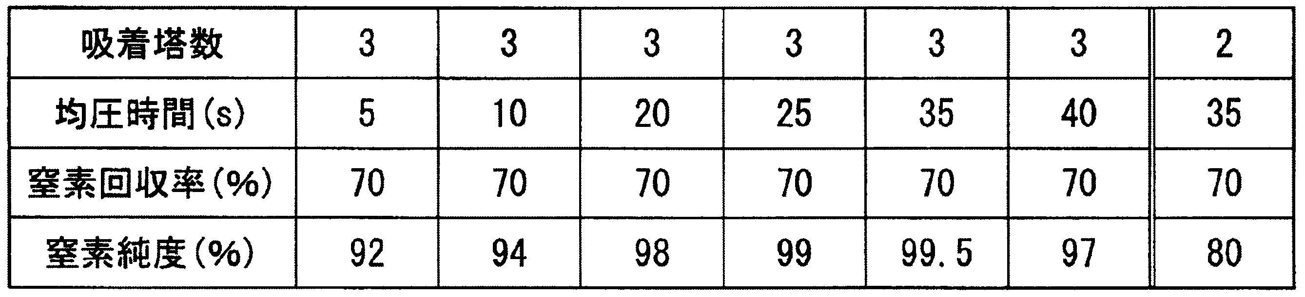
実施例3の比較例として、メタン吸着能力の低い活性炭を使用して、カラム数を2塔としたメタンと窒素の分離実験を行った。吸着塔数以外の条件は実施例3と同じとして、均圧時間は35秒で行った。その結果は表5の最後の欄に記載した。
この結果より、性能の低い活性炭では、2塔式では窒素濃度は80%しかないが、3塔式にすることにより大幅な性能向上が可能で、99%以上の窒素濃度を得られることが判る。
本実施例では、自社で試作した吸着剤により、図7に示す装置を用いてメタンと窒素を分離した。PSA装置の吸着筒には、容積1Lのカラム2筒を用いた。
吸着剤は、ヤシ殻チャーを振動ミル(中央加工機社製)で約5μmに粉砕、バインダーを加えて造粒し、直径が1.4mmのペレット状となるように成形したものをしようした。これを10~15wt%の水蒸気雰囲気下、850℃で賦活処理を行い、処理時間を変えることで賦活程度の異なる5種類の試料サンプルA~サンプルEを試作した。
賦活程度の違いを示す指標として、ここではベンゼン吸着量をJIS K1474に則り測定した。
ベンゼン吸着量は7~38wt%であった。賦活の度合いが大きいほどベンゼン吸着量は大きな値を示す。
また、メタン吸着量を、容量法吸着量測定装置(BELSORP-HP-30、日本ベル株式会社製)にて測定した。試料を約1g採取し、正確な重量を測定後、容量既知のセルに入れる。予め容量を測定したガスタンクにメタンガスを導入し、圧力を記録する。試料を入れたセルとガスタンクをつなぎ、圧力が平衡となるまでその状態を維持する。平衡圧力から、メタンの吸着量を計算する。
PSAの操作条件は、カラムの切り替え時間を240秒、均圧時間を25秒とした。原料ガスのメタンと窒素の比が55:45となるよう供給し、メタン濃度が80%となるように製品窒素量を調整して、その時の窒素濃度およびメタン回収率を測定した。結果を表6に示す。
各サンプルのベンゼン吸着量、200kPaGでのメタン吸着量およびマクロ孔の平均径を、表6に示す。マクロ孔は一次粒子の間隙に由来するものであり、一次粒子径に比例する。
ここで、マクロ孔の平均径は水銀圧入法により0.01μmまでの細孔径分布を測定して求めた値で、測定にはカンタクローム社製水銀ポロシメータ(Pore Master GT)を使用した。
ベンゼン吸着量が10~38wt%、メタン吸着量が1.7~2.3mol/kgのサンプルB~サンプルEにおいて、濃度80%のメタンを99%以上の収率で回収しつつ、99%以上の窒素を分離回収できた。
一方、ベンゼン吸着量が7wt%のサンプルAでは、窒素濃度99%、メタン回収率99%のいずれも達成できていない。
本比較例では、分子ふるい活性炭(MSC)、破砕状活性炭(AC-1)および粒状活性炭(AC-2)を用いてメタンと窒素を分離した。
用いた装置と実施条件は、実施例4と同様の条件とした。
各吸着剤のベンゼン吸着量、200kPaGにおけるメタン平衡吸着量、ペレット径およびマクロ孔の平均径、メタン濃度が80%となるように製品窒素量を調整した時の、窒素濃度およびメタン回収率を表7に示す。
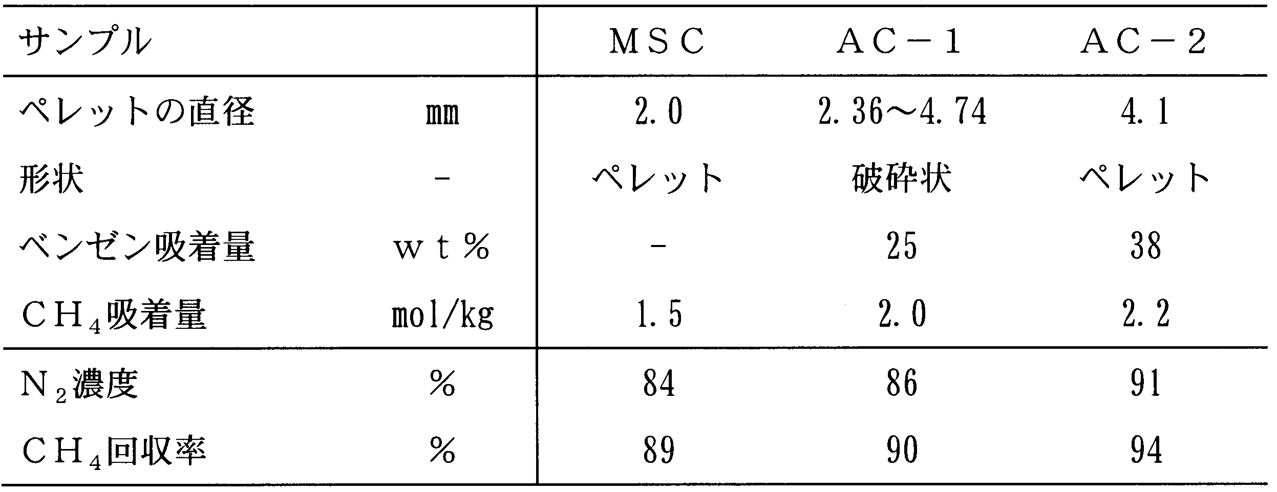
いずれの試料もメタン濃度を80%とすると、窒素濃度が99%を満たさず回収率も95%に達しなかった。
実施例5では、ヤシ殻炭を約8μmに粉砕後、同様に直径2mmのペレット状に造粒したものを使用した。サンプルDと同様にベンゼン吸着量が25wt%となるよう条件を調整して賦活処理を行いサンプルFを得た。
比較例3では、ヤシ殻炭を約20μmに粉砕後、バインダーを加え造粒して直径4mmのペレット状に成形したものを使用した。サンプルD,Fと同様に、ベンゼン吸着量が25wt%となるように賦活条件を調製してサンプルGを得た。
実施例4と同様に、図7に示す装置を用いてメタンと窒素を分離した。ベンゼン吸着量、200kPaGでのメタン吸着量、ペレット径およびマクロ孔の平均径を結果を表8に示す。

サンプルF,Gは、ベンゼン吸着量、メタン吸着量がほぼ変わらないが、メタンと窒素の分離性能に大きな違いがある。
活性炭は平衡分離剤であるため通常使用される条件下ではペレットの直径が性能に与える影響は小さく、吸着塔内での圧力損失が与える影響の方が大きい。よって、圧力損失が小さくなるよう一般的には直径4mm程度のペレット状の吸着剤が使用されている。
一方、速度分離型であるMSCはペレット内のガスの拡散が性能に大きく影響することから、一般に2mm以下のペレット径のものが使用される。
メタン、窒素の分離は平衡吸着分離であり、これまでの常識からいえばペレットの直径が性能に与える影響は小さいはずであるが、その科学的な理由は不明ながら、上記の結果より、ペレット径が小さく一次粒子径が小さい吸着剤ほど、高い分離性能を示すことがわかった。
サンプルDを用いて、カラムの切り替え時間を4分とし、均圧時間を5~40秒に変化させて、メタンと窒素の分離性能の評価を行った。この時、均圧時間終了時に均圧が終了する様に均圧ラインに設置された流量調節弁により均圧ガス流量をコントロールした。メタン濃度が80%になるように製品窒素を取り出した時の、窒素濃度およびメタン回収率を表9に示す。

表9から、均圧時間を長くするほど窒素濃度、メタン回収率ともに向上することが分かる。ただし、均圧時間が長くなるほど原料ガスを導入する圧縮機やメタンガスを回収するための真空ポンプの効率(稼働時間の割合)が低下するため、使用するこれら機器類の性能との兼ね合いより7秒以上で適切な均圧時間を設定すれば良い。
サンプルBを用いて、カラムの切り替え時間を4分とし、均圧時間を25秒として、メタンと窒素の分離性能を調べた。この時、吸着塔AとBの圧力が同じになる時間が5~25秒となる様に均圧ラインに設置された流量調節弁により均圧ガス流量をコントロールした。メタン濃度が80%になるように製品窒素を取り出した時の、窒素純度およびメタン回収率を表10に示す。
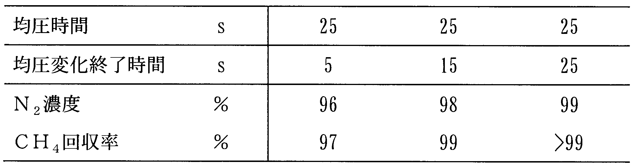
表10から、均圧ガス流量を調節して均圧時間の間に均圧ガスが徐々に流れる様に調節すると窒素濃度、メタン回収率ともに向上することが分かる。
4、5 MFC(マスフローコントローラー)
6~9 圧力計
10 ブロア
11~18、35~49 開閉弁
19 均圧ライン
20、50~55 流量調整弁
21、22、32~34 ガス分離用吸着剤
Claims (9)
- 2塔以上の吸着塔を用いる圧力変動式吸着法によって、主としてメタン及び窒素よりなる混合ガスである原料ガスからメタンと窒素とを分離する方法であって、
前記原料ガスを供給し、吸着塔内の圧力を高める加圧工程、
前記吸着塔に充填されたガス分離用吸着剤にメタンを吸着させ窒素を取り出す吸着工程、
圧力が高められた前記吸着塔内のガスを別の吸着塔に移動させる均圧工程、
前記吸着塔内の圧力を下げて前記ガス分離用吸着剤に吸着されていたメタンを脱離させる再生工程を有しており、
前記加圧工程、前記吸着工程、前記均圧工程、および前記再生工程は、2塔以上の前記吸着塔のそれぞれにおいて行われており、
前記均圧工程において、前記吸着工程終了後の前記吸着塔内のガスは、前記再生工程終了後の前記別の吸着塔に移動し、
前記再生工程において回収されるメタンは、70%以上の濃度かつ95%以上の回収率であり、
前記吸着工程において回収される窒素は、95%以上の濃度であり、
前記ガス分離用吸着剤の平衡吸着量が窒素よりメタンの方が大きいことを特徴とすることを特徴とするメタンと窒素の分離方法。 - 前記ガス分離用吸着剤としてベンゼンの吸着量が10~40wt%の炭素質吸着剤を用い、前記均圧工程の時間を7秒以上35秒以下とすることを特徴とする請求項1に記載のメタンと窒素の分離方法。
- 前記均圧工程の時間は25秒以上35秒以下であることを特徴とする請求項1に記載のメタンと窒素の分離方法。
- 前記均圧工程において、前記吸着塔における圧力変化が均圧工程の初めから終わりまで徐々に行われるように均圧ガスの流量を制御することを特徴とする請求項1に記載のメタンと窒素の分離方法。
- 前記吸着塔が3塔以上であり、前記均圧工程を2回以上段階的に行うことを特徴とする請求項1に記載のメタンと窒素の分離方法。
- 前記均圧工程中の圧力値をフィードバックして、前記均圧ガスの流量を制御することを特徴とする請求項4に記載のメタンと窒素の分離方法。
- 前記吸着工程において、前記原料ガスが充填された前記吸着塔内部の圧力が約0.2MPaGであることを特徴とする請求項1に記載のメタンと窒素の分離方法。
- 前記ガス分離用吸着剤が、ベンゼンの吸着量が10~40wt%、メタンの吸着量が1.7~2.4mol/kg、マクロ孔の平均径が1μm以下であって、直径を2mm以下のペレット状に成形した活性炭系吸着剤であることを特徴とする請求項1に記載のメタンと窒素の分離方法。
- メタンと窒素とを圧力変動式吸着法により分離するためのガス分離用吸着剤であって、ベンゼンの吸着量が10~40wt%、メタンの吸着量が1.7~2.4mol/kg、マクロ孔の平均径が1μm以下であって直径が2mm以下のペレット状に成形した活性炭系吸着剤であることを特徴とするガス分離用吸着剤。
Priority Applications (2)
| Application Number | Priority Date | Filing Date | Title |
|---|---|---|---|
| JP2015515904A JP5901849B2 (ja) | 2013-05-10 | 2014-05-09 | メタンと窒素の分離方法 |
| CN201480025441.5A CN105188885A (zh) | 2013-05-10 | 2014-05-09 | 甲烷和氮的分离方法 |
Applications Claiming Priority (2)
| Application Number | Priority Date | Filing Date | Title |
|---|---|---|---|
| JP2013100598 | 2013-05-10 | ||
| JP2013-100598 | 2013-05-10 |
Publications (1)
| Publication Number | Publication Date |
|---|---|
| WO2014181860A1 true WO2014181860A1 (ja) | 2014-11-13 |
Family
ID=51867332
Family Applications (1)
| Application Number | Title | Priority Date | Filing Date |
|---|---|---|---|
| PCT/JP2014/062450 Ceased WO2014181860A1 (ja) | 2013-05-10 | 2014-05-09 | メタンと窒素の分離方法 |
Country Status (4)
| Country | Link |
|---|---|
| JP (1) | JP5901849B2 (ja) |
| CN (1) | CN105188885A (ja) |
| MY (1) | MY160494A (ja) |
| WO (1) | WO2014181860A1 (ja) |
Cited By (4)
| Publication number | Priority date | Publication date | Assignee | Title |
|---|---|---|---|---|
| JP2016187778A (ja) * | 2015-03-30 | 2016-11-04 | 住友精化株式会社 | 圧力変動吸着装置およびガス分離方法 |
| CN112742172A (zh) * | 2019-10-31 | 2021-05-04 | 中国石油化工股份有限公司 | 一种能源气体净化方法 |
| CN112742170A (zh) * | 2019-10-31 | 2021-05-04 | 中国石油化工股份有限公司 | 一种高含氮能源气体净化方法 |
| WO2024036169A1 (en) * | 2022-08-09 | 2024-02-15 | Archaea Energy, Inc. | Nitrogen removal system for methane purification from landfill gas, and method thereof |
Families Citing this family (1)
| Publication number | Priority date | Publication date | Assignee | Title |
|---|---|---|---|---|
| CN114437846B (zh) * | 2020-11-04 | 2023-01-10 | 中国石油化工股份有限公司 | 一种基于计算机的天然气变压吸附脱氮的优化方法 |
Citations (6)
| Publication number | Priority date | Publication date | Assignee | Title |
|---|---|---|---|---|
| JPS61178014A (ja) * | 1985-01-31 | 1986-08-09 | Nippon Sanso Kk | 吸着器の定風量均圧方法 |
| US5536300A (en) * | 1994-10-21 | 1996-07-16 | Nitrotec Corporation | Natural gas enrichment process |
| US5792239A (en) * | 1994-10-21 | 1998-08-11 | Nitrotec Corporation | Separation of gases by pressure swing adsorption |
| JP2000312824A (ja) * | 1999-03-04 | 2000-11-14 | Takeda Chem Ind Ltd | メタンと窒素の混合ガスからメタンを分離するモレキュラーシービングカーボン |
| WO2008053680A1 (fr) * | 2006-10-31 | 2008-05-08 | Osaka Gas Co., Ltd. | Dispositif et procédé pour la concentration de gaz inflammable |
| JP2012144628A (ja) * | 2011-01-12 | 2012-08-02 | Air Water Inc | メタンを主成分とするガスの窒素除去方法および装置 |
Family Cites Families (3)
| Publication number | Priority date | Publication date | Assignee | Title |
|---|---|---|---|---|
| JPH06154595A (ja) * | 1992-11-19 | 1994-06-03 | Kanebo Ltd | 圧力スイング吸着装置用分子ふるい炭素 |
| CN101935032B (zh) * | 2010-09-03 | 2012-11-07 | 同济大学 | 一种炭分子筛的制备方法及其用途 |
| CN202237712U (zh) * | 2011-10-11 | 2012-05-30 | 北京科技大学 | 多塔真空变压吸附法提浓煤矿乏风瓦斯的装置 |
-
2014
- 2014-05-09 CN CN201480025441.5A patent/CN105188885A/zh active Pending
- 2014-05-09 JP JP2015515904A patent/JP5901849B2/ja active Active
- 2014-05-09 MY MYPI2015703932A patent/MY160494A/en unknown
- 2014-05-09 WO PCT/JP2014/062450 patent/WO2014181860A1/ja not_active Ceased
Patent Citations (6)
| Publication number | Priority date | Publication date | Assignee | Title |
|---|---|---|---|---|
| JPS61178014A (ja) * | 1985-01-31 | 1986-08-09 | Nippon Sanso Kk | 吸着器の定風量均圧方法 |
| US5536300A (en) * | 1994-10-21 | 1996-07-16 | Nitrotec Corporation | Natural gas enrichment process |
| US5792239A (en) * | 1994-10-21 | 1998-08-11 | Nitrotec Corporation | Separation of gases by pressure swing adsorption |
| JP2000312824A (ja) * | 1999-03-04 | 2000-11-14 | Takeda Chem Ind Ltd | メタンと窒素の混合ガスからメタンを分離するモレキュラーシービングカーボン |
| WO2008053680A1 (fr) * | 2006-10-31 | 2008-05-08 | Osaka Gas Co., Ltd. | Dispositif et procédé pour la concentration de gaz inflammable |
| JP2012144628A (ja) * | 2011-01-12 | 2012-08-02 | Air Water Inc | メタンを主成分とするガスの窒素除去方法および装置 |
Cited By (4)
| Publication number | Priority date | Publication date | Assignee | Title |
|---|---|---|---|---|
| JP2016187778A (ja) * | 2015-03-30 | 2016-11-04 | 住友精化株式会社 | 圧力変動吸着装置およびガス分離方法 |
| CN112742172A (zh) * | 2019-10-31 | 2021-05-04 | 中国石油化工股份有限公司 | 一种能源气体净化方法 |
| CN112742170A (zh) * | 2019-10-31 | 2021-05-04 | 中国石油化工股份有限公司 | 一种高含氮能源气体净化方法 |
| WO2024036169A1 (en) * | 2022-08-09 | 2024-02-15 | Archaea Energy, Inc. | Nitrogen removal system for methane purification from landfill gas, and method thereof |
Also Published As
| Publication number | Publication date |
|---|---|
| MY160494A (en) | 2017-03-15 |
| CN105188885A (zh) | 2015-12-23 |
| JPWO2014181860A1 (ja) | 2017-02-23 |
| JP5901849B2 (ja) | 2016-04-13 |
Similar Documents
| Publication | Publication Date | Title |
|---|---|---|
| TWI521056B (zh) | Methane recovery method and methane recovery unit | |
| JP5901849B2 (ja) | メタンと窒素の分離方法 | |
| JP4972467B2 (ja) | 低純度窒素ガス発生方法 | |
| CA3033841C (en) | Method for recovering hydrogen from biomass pyrolysis gas | |
| US9944575B2 (en) | Methane gas concentration method | |
| JP5319140B2 (ja) | 高炉ガスの分離方法、および高炉ガスの分離システム | |
| US10722836B2 (en) | Hydrogen recovery method | |
| CN110198775A (zh) | 气体分离回收方法及设备 | |
| US8128735B1 (en) | Process for CO2 capture using zeolites from high pressure and moderate temperature gas streams | |
| KR101805943B1 (ko) | 프로판의 정제 방법 및 정제 장치 | |
| US20120279391A1 (en) | Adsorption process to recover carbon dioxide from flue gas | |
| JP4531291B2 (ja) | 水素精製用4塔式圧力スイング吸着装置の安定運転方法 | |
| CN103113946B (zh) | 沼气净化系统及沼气净化方法 | |
| JPH02699A (ja) | 都市ガス製造プロセスに於けるガス中の炭酸ガス及び水分を除去する方法 | |
| CN220424946U (zh) | 一种二氧化碳提纯装置 | |
| CN104357118B (zh) | 一种提高液化天然气回收率的方法 | |
| CN104312650B (zh) | 一种提高液化天然气回收率的系统 | |
| CN115779682B (zh) | 一种一氧化碳原料气的靶向净化系统 | |
| CN110694425B (zh) | 一种含氯化有机物混合气的氯化有机物低能耗回收改进工艺 | |
| JP2025539265A (ja) | 炭化水素から水素を分離するためのプロセス及び装置 | |
| WO2024024572A1 (ja) | Co2分離システム | |
| CN114180529A (zh) | 一种医用氧气的提纯装置及方法 | |
| KR20240069331A (ko) | 이산화탄소 정제 시스템 및 이산화탄소 정제 방법 | |
| Mhdi | Capture of CO2 from power plants Using Different Adsorbent materials | |
| JP2011251864A (ja) | 高圧下における二酸化炭素の分離装置及びその方法 |
Legal Events
| Date | Code | Title | Description |
|---|---|---|---|
| WWE | Wipo information: entry into national phase |
Ref document number: 201480025441.5 Country of ref document: CN |
|
| 121 | Ep: the epo has been informed by wipo that ep was designated in this application |
Ref document number: 14795122 Country of ref document: EP Kind code of ref document: A1 |
|
| DPE1 | Request for preliminary examination filed after expiration of 19th month from priority date (pct application filed from 20040101) | ||
| ENP | Entry into the national phase |
Ref document number: 2015515904 Country of ref document: JP Kind code of ref document: A |
|
| NENP | Non-entry into the national phase |
Ref country code: DE |
|
| WWE | Wipo information: entry into national phase |
Ref document number: IDP00201508164 Country of ref document: ID |
|
| 122 | Ep: pct application non-entry in european phase |
Ref document number: 14795122 Country of ref document: EP Kind code of ref document: A1 |