WO2014178594A1 - 이차전지의 제조 방법 및 이를 이용한 이차전지 - Google Patents
이차전지의 제조 방법 및 이를 이용한 이차전지 Download PDFInfo
- Publication number
- WO2014178594A1 WO2014178594A1 PCT/KR2014/003750 KR2014003750W WO2014178594A1 WO 2014178594 A1 WO2014178594 A1 WO 2014178594A1 KR 2014003750 W KR2014003750 W KR 2014003750W WO 2014178594 A1 WO2014178594 A1 WO 2014178594A1
- Authority
- WO
- WIPO (PCT)
- Prior art keywords
- secondary battery
- battery
- battery case
- electrode assembly
- formula
- Prior art date
- Legal status (The legal status is an assumption and is not a legal conclusion. Google has not performed a legal analysis and makes no representation as to the accuracy of the status listed.)
- Ceased
Links
Images



Classifications
-
- H—ELECTRICITY
- H01—ELECTRIC ELEMENTS
- H01M—PROCESSES OR MEANS, e.g. BATTERIES, FOR THE DIRECT CONVERSION OF CHEMICAL ENERGY INTO ELECTRICAL ENERGY
- H01M50/00—Constructional details or processes of manufacture of the non-active parts of electrochemical cells other than fuel cells, e.g. hybrid cells
- H01M50/30—Arrangements for facilitating escape of gases
-
- H—ELECTRICITY
- H01—ELECTRIC ELEMENTS
- H01M—PROCESSES OR MEANS, e.g. BATTERIES, FOR THE DIRECT CONVERSION OF CHEMICAL ENERGY INTO ELECTRICAL ENERGY
- H01M10/00—Secondary cells; Manufacture thereof
- H01M10/04—Construction or manufacture in general
- H01M10/0422—Cells or battery with cylindrical casing
-
- H—ELECTRICITY
- H01—ELECTRIC ELEMENTS
- H01M—PROCESSES OR MEANS, e.g. BATTERIES, FOR THE DIRECT CONVERSION OF CHEMICAL ENERGY INTO ELECTRICAL ENERGY
- H01M10/00—Secondary cells; Manufacture thereof
- H01M10/05—Accumulators with non-aqueous electrolyte
- H01M10/052—Li-accumulators
-
- H—ELECTRICITY
- H01—ELECTRIC ELEMENTS
- H01M—PROCESSES OR MEANS, e.g. BATTERIES, FOR THE DIRECT CONVERSION OF CHEMICAL ENERGY INTO ELECTRICAL ENERGY
- H01M10/00—Secondary cells; Manufacture thereof
- H01M10/05—Accumulators with non-aqueous electrolyte
- H01M10/058—Construction or manufacture
-
- H—ELECTRICITY
- H01—ELECTRIC ELEMENTS
- H01M—PROCESSES OR MEANS, e.g. BATTERIES, FOR THE DIRECT CONVERSION OF CHEMICAL ENERGY INTO ELECTRICAL ENERGY
- H01M10/00—Secondary cells; Manufacture thereof
- H01M10/42—Methods or arrangements for servicing or maintenance of secondary cells or secondary half-cells
- H01M10/52—Removing gases inside the secondary cell, e.g. by absorption
-
- H—ELECTRICITY
- H01—ELECTRIC ELEMENTS
- H01M—PROCESSES OR MEANS, e.g. BATTERIES, FOR THE DIRECT CONVERSION OF CHEMICAL ENERGY INTO ELECTRICAL ENERGY
- H01M10/00—Secondary cells; Manufacture thereof
- H01M10/42—Methods or arrangements for servicing or maintenance of secondary cells or secondary half-cells
- H01M10/52—Removing gases inside the secondary cell, e.g. by absorption
- H01M10/526—Removing gases inside the secondary cell, e.g. by absorption by gas recombination on the electrode surface or by structuring the electrode surface to improve gas recombination
-
- H—ELECTRICITY
- H01—ELECTRIC ELEMENTS
- H01M—PROCESSES OR MEANS, e.g. BATTERIES, FOR THE DIRECT CONVERSION OF CHEMICAL ENERGY INTO ELECTRICAL ENERGY
- H01M4/00—Electrodes
- H01M4/02—Electrodes composed of, or comprising, active material
- H01M4/36—Selection of substances as active materials, active masses, active liquids
- H01M4/48—Selection of substances as active materials, active masses, active liquids of inorganic oxides or hydroxides
- H01M4/50—Selection of substances as active materials, active masses, active liquids of inorganic oxides or hydroxides of manganese
- H01M4/505—Selection of substances as active materials, active masses, active liquids of inorganic oxides or hydroxides of manganese of mixed oxides or hydroxides containing manganese for inserting or intercalating light metals, e.g. LiMn2O4 or LiMn2OxFy
-
- H—ELECTRICITY
- H01—ELECTRIC ELEMENTS
- H01M—PROCESSES OR MEANS, e.g. BATTERIES, FOR THE DIRECT CONVERSION OF CHEMICAL ENERGY INTO ELECTRICAL ENERGY
- H01M4/00—Electrodes
- H01M4/02—Electrodes composed of, or comprising, active material
- H01M4/36—Selection of substances as active materials, active masses, active liquids
- H01M4/48—Selection of substances as active materials, active masses, active liquids of inorganic oxides or hydroxides
- H01M4/52—Selection of substances as active materials, active masses, active liquids of inorganic oxides or hydroxides of nickel, cobalt or iron
- H01M4/525—Selection of substances as active materials, active masses, active liquids of inorganic oxides or hydroxides of nickel, cobalt or iron of mixed oxides or hydroxides containing iron, cobalt or nickel for inserting or intercalating light metals, e.g. LiNiO2, LiCoO2 or LiCoOxFy
-
- H—ELECTRICITY
- H01—ELECTRIC ELEMENTS
- H01M—PROCESSES OR MEANS, e.g. BATTERIES, FOR THE DIRECT CONVERSION OF CHEMICAL ENERGY INTO ELECTRICAL ENERGY
- H01M50/00—Constructional details or processes of manufacture of the non-active parts of electrochemical cells other than fuel cells, e.g. hybrid cells
- H01M50/50—Current conducting connections for cells or batteries
- H01M50/572—Means for preventing undesired use or discharge
-
- H—ELECTRICITY
- H01—ELECTRIC ELEMENTS
- H01M—PROCESSES OR MEANS, e.g. BATTERIES, FOR THE DIRECT CONVERSION OF CHEMICAL ENERGY INTO ELECTRICAL ENERGY
- H01M4/00—Electrodes
- H01M4/02—Electrodes composed of, or comprising, active material
- H01M2004/026—Electrodes composed of, or comprising, active material characterised by the polarity
- H01M2004/027—Negative electrodes
-
- H—ELECTRICITY
- H01—ELECTRIC ELEMENTS
- H01M—PROCESSES OR MEANS, e.g. BATTERIES, FOR THE DIRECT CONVERSION OF CHEMICAL ENERGY INTO ELECTRICAL ENERGY
- H01M4/00—Electrodes
- H01M4/02—Electrodes composed of, or comprising, active material
- H01M4/04—Processes of manufacture in general
- H01M4/043—Processes of manufacture in general involving compressing or compaction
-
- H—ELECTRICITY
- H01—ELECTRIC ELEMENTS
- H01M—PROCESSES OR MEANS, e.g. BATTERIES, FOR THE DIRECT CONVERSION OF CHEMICAL ENERGY INTO ELECTRICAL ENERGY
- H01M4/00—Electrodes
- H01M4/02—Electrodes composed of, or comprising, active material
- H01M4/24—Electrodes for alkaline accumulators
- H01M4/26—Processes of manufacture
- H01M4/30—Pressing
-
- H—ELECTRICITY
- H01—ELECTRIC ELEMENTS
- H01M—PROCESSES OR MEANS, e.g. BATTERIES, FOR THE DIRECT CONVERSION OF CHEMICAL ENERGY INTO ELECTRICAL ENERGY
- H01M50/00—Constructional details or processes of manufacture of the non-active parts of electrochemical cells other than fuel cells, e.g. hybrid cells
- H01M50/50—Current conducting connections for cells or batteries
- H01M50/572—Means for preventing undesired use or discharge
- H01M50/574—Devices or arrangements for the interruption of current
- H01M50/578—Devices or arrangements for the interruption of current in response to pressure
-
- Y—GENERAL TAGGING OF NEW TECHNOLOGICAL DEVELOPMENTS; GENERAL TAGGING OF CROSS-SECTIONAL TECHNOLOGIES SPANNING OVER SEVERAL SECTIONS OF THE IPC; TECHNICAL SUBJECTS COVERED BY FORMER USPC CROSS-REFERENCE ART COLLECTIONS [XRACs] AND DIGESTS
- Y02—TECHNOLOGIES OR APPLICATIONS FOR MITIGATION OR ADAPTATION AGAINST CLIMATE CHANGE
- Y02E—REDUCTION OF GREENHOUSE GAS [GHG] EMISSIONS, RELATED TO ENERGY GENERATION, TRANSMISSION OR DISTRIBUTION
- Y02E60/00—Enabling technologies; Technologies with a potential or indirect contribution to GHG emissions mitigation
- Y02E60/10—Energy storage using batteries
-
- Y—GENERAL TAGGING OF NEW TECHNOLOGICAL DEVELOPMENTS; GENERAL TAGGING OF CROSS-SECTIONAL TECHNOLOGIES SPANNING OVER SEVERAL SECTIONS OF THE IPC; TECHNICAL SUBJECTS COVERED BY FORMER USPC CROSS-REFERENCE ART COLLECTIONS [XRACs] AND DIGESTS
- Y02—TECHNOLOGIES OR APPLICATIONS FOR MITIGATION OR ADAPTATION AGAINST CLIMATE CHANGE
- Y02P—CLIMATE CHANGE MITIGATION TECHNOLOGIES IN THE PRODUCTION OR PROCESSING OF GOODS
- Y02P70/00—Climate change mitigation technologies in the production process for final industrial or consumer products
- Y02P70/50—Manufacturing or production processes characterised by the final manufactured product
Definitions
- the present invention relates to a method of manufacturing a secondary battery in which an electrode assembly is sealed inside a battery case, and a secondary battery using the same.
- lithium secondary batteries with high energy density and voltage, long cycle life, and low self discharge rate It is commercially used and widely used.
- Lithium metal oxide which is most commonly used as a cathode of lithium secondary batteries, is usually formed by reacting lithium carbonate with carbonate. If stoichiometrically, the amount of lithium carbonate is increased, the remaining amount of lithium carbonate is decomposed at high temperature. Various kinds of gases such as carbon and hydrogen are generated.
- the electrolyte may decompose to form a gas even when the electrolyte reacts with impurities and lithium ions on the surface of the battery negative electrode to form a solid electrolyte film.
- the internally generated gas such as carbon dioxide is reversible to be charged back to the original material while being charged depending on conditions, but usually remains in a gaseous state in the cell to increase internal pressure and cause swelling to inflate electricity.
- the swelling of the battery is too thick to be mounted on an electronic device designed to be mounted, or it is judged to be defective due to a bulging appearance and loses its value as a product.
- the essential consideration in the development of the lithium secondary battery is to ensure safety by preventing or eliminating the generation of internal gas causing fire / explosion and swelling at high temperature.
- the present invention aims to solve the problems of the prior art as described above and the technical problems that have been requested from the past.
- the inventors of the present application after repeated in-depth research and various experiments, pressurizes both sides of the battery case in which the electrode assembly is embedded to increase the pressure inside the battery case, as will be described later.
- produces in the charge / discharge process of a battery can be achieved, and the desired effect can be achieved, and came to complete this invention.
- the present invention provides a method of manufacturing a secondary battery in which the electrode assembly is sealed in the battery case.
- the electrode assembly includes a lithium nickel manganese composite oxide having a spinel structure represented by Chemical Formula 1 as a cathode active material, and a lithium metal oxide represented by Chemical Formula 2 as a negative electrode active material. It relates to a manufacturing method.
- M is at least one element selected from the group consisting of Al, Mg, Ni, Co, Fe, Cr, V, Ti, Cu, B, Ca, Zn, Zr, Nb, Mo, Sr, Sb, W, Ti and Bi Is;
- A is -1 or -divalent one or more anions
- M ' is at least one element selected from the group consisting of Ti, Sn, Cu, Pb, Sb, Zn, Fe, In, Al and Zr;
- a and b are 0.1 ⁇ a ⁇ 4; Determined according to the oxidation number of M 'in the range of 0.2 ⁇ b ⁇ 4;
- c is determined depending on the oxidation number in the range of 0 ⁇ c ⁇ 0.2;
- A is -1 or -divalent one or more anions.
- Le Chartelier's principle is the principle of thermodynamic equilibrium shift, which is omitted since it is well known in the art.
- the "gas" is an operating state in which the temperature of the battery rises above the temperature of the normal operating state due to an abnormal reaction of the electrolyte and / or the electrode during the operation of the battery such as overcharge, external or internal short circuit, needle penetration, local damage, and the like. It means a gas such as carbon monoxide, carbon dioxide, hydrogen can be generated from.
- a lithium nickel manganese composite oxide having a spinel structure using lithium titanium oxide as a negative electrode active material and having a high potential of 4.7 V is used.
- the electrolyte may appear when using the electrode active material exhibiting a high potential, including the process of removing the gas as described above can also improve the safety by preventing the generation of by-products such as gas due to oxidation.
- the oxide of Formula 1 may be represented by the following Formula 3.
- the oxide of Formula 1 may be LiNi 0.5 Mn 1.5 O 4 or LiNi 0.4 Mn 1.6 O 4 .
- oxide of Chemical Formula 2 may be represented by Chemical Formula 4 below.
- the lithium metal oxide may be Li 1.33 Ti 1.67 O 4 or LiTi 2 O 4 .
- the lithium titanium oxide has a higher potential with respect to lithium than graphite and has excellent safety because lithium reactants and lithium do not precipitate at the interface.
- lithium titanium oxide has a high potential of about 1.5 V with respect to lithium, when used with a conventionally used positive electrode active material such as lithium cobalt oxide, the discharge voltage of the battery cell drops to about 2.4 V, and the theoretical capacity is also 175 mAh /. It is similar to graphite in g, so there is a limit in improving energy density.
- a lithium nickel manganese composite oxide having a lithium titanium oxide as a negative electrode active material and a spinel structure having a high potential of 4.7 V can be used to maintain a high voltage and exhibit excellent capacity and output characteristics.
- the electrolyte may be oxidized to further induce the generation of by-products such as gas, and thus the present invention includes a process of removing such gas, thereby providing excellent capacity and output. In addition to exhibiting characteristics, it can further improve safety.
- the pressurization of this step (b) may be at a size of 2 to 10 atm, and more particularly at a size of 3 to 8 atm. If the magnitude of such pressurization is too large, the particle diameter of the center portion of the battery case may be too small, which may cause damage to the built-in electrode assembly, which is not preferable. When the size is too small, the effect intended by the present invention may be sufficiently exhibited. It is not desirable because it cannot.
- the pressurization can be carried out in various ways known in the art. For example, it is possible to increase the pressure in the device by inserting a cell in a predetermined device, in detail, it can be carried out by pressing the battery case with the pressing plate using the pressing plate on both sides of the battery case.
- the secondary battery is a cylindrical battery and a rectangular battery in which the electrode assembly is embedded in a cylindrical or rectangular metal can, and a pouch type battery in which the electrode assembly is embedded in a pouch type case of an aluminum laminate sheet according to the shape of the battery case.
- the manufacturing method according to the present invention includes a pressing step of the battery case, in detail, a battery case made of a metal can of a rectangular or cylindrical shape may be used.
- the present invention provides a secondary battery manufactured by the above manufacturing method.
- the amount of gas present in the battery case is 5 to 60% of the total weight of the gas present in the battery case of the secondary battery that is not pressurized. It may be, in detail may be 5 to 40%.
- the internal pressure of the battery case of the secondary battery that is pressurized may represent 1.2 to 10 atm, and in detail, 3 to 8 atm due to the gas present therein.
- the secondary battery may be a lithium secondary battery.
- Such a lithium secondary battery is a cathode prepared by applying a mixture of a cathode active material, a conductive material and a binder on a cathode current collector, followed by drying and pressing, and a cathode prepared by applying a mixture of an anode active material and a binder, followed by drying and pressing.
- a filler may be further added to the mixture, if necessary.
- the positive electrode current collector is generally made to a thickness of 3 to 500 ⁇ m. Such a positive electrode current collector is not particularly limited as long as it has high conductivity without causing chemical change in the battery. For example, stainless steel, aluminum, nickel, titanium, calcined carbon, or aluminum or stainless steel Surface-treated with carbon, nickel, titanium, silver, and the like may be used.
- the current collector may form fine irregularities on its surface to increase the adhesion of the positive electrode active material, and may be in various forms such as a film, a sheet, a foil, a net, a porous body, a foam, and a nonwoven fabric.
- the positive electrode active material may be a material defined above, but, for example, layered layers such as lithium cobalt oxide (LiCoO 2 ), lithium nickel oxide (LiNiO 2 ), etc., within 30 to 50 wt% based on the total weight of the positive electrode active material.
- layered layers such as lithium cobalt oxide (LiCoO 2 ), lithium nickel oxide (LiNiO 2 ), etc., within 30 to 50 wt% based on the total weight of the positive electrode active material.
- the conductive material is typically added in an amount of 1 to 50% by weight based on the total weight of the mixture including the positive electrode active material.
- a conductive material is not particularly limited as long as it has conductivity without causing chemical change in the battery, and examples thereof include graphite such as natural graphite and artificial graphite; Carbon blacks such as carbon black, acetylene black, Ketjen black, channel black, furnace black, lamp black, and summer black; Conductive fibers such as carbon fibers and metal fibers; Metal powders such as carbon fluoride powder, aluminum powder and nickel powder; Conductive whiskeys such as zinc oxide and potassium titanate; Conductive metal oxides such as titanium oxide; Conductive materials such as polyphenylene derivatives and the like can be used.
- the binder is a component that assists in bonding the active material and the conductive material to the current collector, and is generally added in an amount of 1 to 50 wt% based on the total weight of the mixture including the positive electrode active material.
- binders include polyvinylidene fluoride, polyvinyl alcohol, carboxymethyl cellulose (CMC), starch, hydroxypropyl cellulose, regenerated cellulose, polyvinylpyrrolidone, tetrafluoroethylene, polyethylene , Polypropylene, ethylene-propylene-diene terpolymer (EPDM), sulfonated EPDM, styrene butylene rubber, fluorine rubber, various copolymers and the like.
- the filler is optionally used as a component for inhibiting expansion of the positive electrode, and is not particularly limited as long as it is a fibrous material without causing chemical change in the battery.
- the filler include olefinic polymers such as polyethylene and polypropylene; Fibrous materials, such as glass fiber and carbon fiber, are used.
- the negative electrode current collector is generally made of a thickness of 3 ⁇ 500 ⁇ m.
- a negative electrode current collector is not particularly limited as long as it has conductivity without causing chemical change in the battery.
- the surface of copper, stainless steel, aluminum, nickel, titanium, calcined carbon, copper or stainless steel Surface-treated with carbon, nickel, titanium, silver, and the like, aluminum-cadmium alloy, and the like can be used.
- fine concavities and convexities may be formed on the surface to enhance the bonding strength of the negative electrode active material, and may be used in various forms such as a film, a sheet, a foil, a net, a porous body, a foam, and a nonwoven fabric.
- the negative electrode active material may be, for example, a material as defined above, but may be further added within 30 to 50% by weight based on the total weight of the negative electrode active material, such as non-graphitized carbon and graphite carbon; Li x Fe 2 O 3 (0 ⁇ x ⁇ 1), Li x WO 2 (0 ⁇ x ⁇ 1), Sn x Me 1-x Me ' y O z (Me: Mn, Fe, Pb, Ge; Me' Metal complex oxides such as Al, B, P, Si, Group 1, Group 2, Group 3 elements of the periodic table, halogen, 0 ⁇ x ⁇ 1; 1 ⁇ y ⁇ 3; 1 ⁇ z ⁇ 8); Lithium metal; Lithium alloys; Silicon-based alloys; Tin-based alloys; SnO, SnO 2 , PbO, PbO 2 , Pb 2 O 3 , Pb 3 O 4 , Sb 2 O 3 , Sb 2 O 4 , Sb 2 O 5 , Ge
- the secondary battery may have a structure in which a lithium salt-containing electrolyte is impregnated in an electrode assembly having a separator interposed between a positive electrode and a negative electrode.
- the separator is interposed between the anode and the cathode, and an insulating thin film having high ion permeability and mechanical strength is used.
- the pore diameter of the separator is generally from 0.01 to 10 ⁇ m ⁇ m, thickness is generally 5 ⁇ 300 ⁇ m.
- a separator for example, olefin polymers such as chemical resistance and hydrophobic polypropylene; Sheets or non-woven fabrics made of glass fibers or polyethylene are used.
- a solid electrolyte such as a polymer
- the solid electrolyte may also serve as a separator.
- the lithium salt-containing electrolyte solution is composed of an electrolyte solution and a lithium salt, and the electrolyte solution, but non-aqueous organic solvent, organic solid electrolyte, inorganic solid electrolyte and the like are used, but are not limited thereto.
- non-aqueous organic solvent examples include N-methyl-2-pyrrolidinone, propylene carbonate, ethylene carbonate, butylene carbonate, dimethyl carbonate, diethyl carbonate, and gamma Butyl lactone, 1,2-dimethoxy ethane, tetrahydroxy franc, 2-methyl tetrahydrofuran, dimethyl sulfoxide, 1,3-dioxorone, formamide, dimethylformamide, dioxolon , Acetonitrile, nitromethane, methyl formate, methyl acetate, phosphate triester, trimethoxy methane, dioxorone derivatives, sulfolane, methyl sulfolane, 1,3-dimethyl-2-imidazolidinone, propylene carbo Aprotic organic solvents such as nate derivatives, tetrahydrofuran derivatives, ethers, methyl pyroionate and ethyl propionate can be
- organic solid electrolyte examples include polyethylene derivatives, polyethylene oxide derivatives, polypropylene oxide derivatives, phosphate ester polymers, polyedgetion lysine, polyester sulfides, polyvinyl alcohols, polyvinylidene fluorides, Polymerizers containing ionic dissociating groups and the like can be used.
- the lithium salt is a good material to be dissolved in the non-aqueous electrolyte, for example, LiCl, LiBr, LiI, LiClO 4 , LiBF 4 , LiB 10 Cl 10 , LiPF 6 , LiCF 3 SO 3 , LiCF 3 CO 2 , LiAsF 6, LiSbF 6, LiAlCl 4, CH 3 SO 3 Li, (CF 3 SO 2) 2 NLi, chloroborane lithium, lower aliphatic carboxylic acid lithium, lithium tetraphenyl borate and imide.
- pyridine triethyl phosphite, triethanolamine, cyclic ether, ethylene diamine, n-glyme, hexaphosphate triamide, nitro Benzene derivatives, sulfur, quinone imine dyes, N-substituted oxazolidinones, N, N-substituted imidazolidines, ethylene glycol dialkyl ethers, ammonium salts, pyrroles, 2-methoxy ethanol, aluminum trichloride and the like may be added. .
- a halogen-containing solvent such as carbon tetrachloride or ethylene trifluoride may be further included, and carbon dioxide gas may be further included to improve high temperature storage characteristics, and FEC (Fluoro-Ethylene) may be further included. Carbonate), PRS (Propene sultone) may be further included.
- lithium salts such as LiPF 6 , LiClO 4 , LiBF 4 , LiN (SO 2 CF 3 ) 2, and the like, may be prepared by cyclic carbonate of EC or PC as a highly dielectric solvent and DEC, DMC or EMC as a low viscosity solvent.
- Lithium salt-containing non-aqueous electrolyte can be prepared by adding to a mixed solvent of linear carbonate.
- a battery module including the secondary battery as a unit cell may be manufactured, and a battery pack may be manufactured including the battery module.
- the battery pack may be used as a power source for medium and large devices requiring high temperature stability, long cycle characteristics, high rate characteristics, and the like.
- the medium-to-large device include a power tool driven by an electric motor; Electric vehicles including electric vehicles (EVs), hybrid electric vehicles (HEVs), plug-in hybrid electric vehicles (PHEVs), and the like; Electric motorcycles including electric bicycles (E-bikes) and electric scooters (E-scooters); Electric golf carts; Power storage systems and the like, but is not limited thereto.
- Electric vehicles including electric vehicles (EVs), hybrid electric vehicles (HEVs), plug-in hybrid electric vehicles (PHEVs), and the like
- Electric motorcycles including electric bicycles (E-bikes) and electric scooters (E-scooters); Electric golf carts; Power storage systems and the like, but is not limited thereto.
- Example 1 is a graph showing the cycle characteristics of the secondary battery of Example 1 in Experimental Example 1 of the present invention
- the negative electrode was prepared by applying, drying and pressing at a loading amount of / cm 2 .
- Ethylene carbonate (EC): Dimethyl carbonate (DMC): Ethyl methyl carbonate (EMC) 3: 4: 3 containing 1 M LiPF 6 in a solvent to prepare a secondary battery electrolyte.
- DMC Dimethyl carbonate
- EMC Ethyl methyl carbonate
- step (b) both sides of the battery case in which the electrode assembly is built are pressed to 3 atm to increase the pressure inside the battery case.
- a lithium secondary battery was manufactured in the same manner as in Example 1, except that both sides of the battery case were not pressed in the step (b) of Example 1.
- the lithium secondary batteries prepared in Example 1 and Comparative Example 1 measured the rate characteristics after 0.5C charge and 0.5C discharge and are shown in FIGS. 1 and 2, respectively.
- the battery of Example 1 to which external pressure is applied in a secondary battery manufacturing process, has a constant cycle characteristic of the battery due to the suppression or consumption of gas, whereas the battery of Comparative Example 1 does not apply external pressure to FIG. 2.
- the cycle characteristics of the battery are not constant due to the large amount of gas present in the secondary battery case. This is because when the external pressure is applied, the inside of the secondary battery case is in a high pressure state, so that side reactions in which gas is generated is reduced, and the generated gas is dissolved in the electrolyte under a high pressure environment, thereby reducing the uneven reaction caused by undissolved gas bubbles. .
- the lithium secondary batteries prepared in Example 1 and Comparative Example 1 were 0.5C charged and 0.5C discharged, and the batteries were disassembled and photographed as shown in FIGS. 3 and 4, respectively.
- the battery according to Example 1 which is subjected to external pressure, may be confirmed that the separator is uniform because the amount of gas and non-uniform reaction present in the battery is reduced for the reasons described above.
- Figure 4 it can be seen that the cell according to Comparative Example 1 is not applied to the external pressure because a large amount of gas is present inside the cell because the heterogeneous reaction occurs, the separation membrane is nonuniform.
- the method of manufacturing a secondary battery according to the present invention increases the pressure inside the battery case by pressing both sides of the battery case in which the electrode assembly is embedded, thereby generating carbon dioxide during charge and discharge of the battery. At the same time, the gas already generated can be reduced and consumed at the cathode.
Landscapes
- Chemical & Material Sciences (AREA)
- Chemical Kinetics & Catalysis (AREA)
- Electrochemistry (AREA)
- General Chemical & Material Sciences (AREA)
- Engineering & Computer Science (AREA)
- Manufacturing & Machinery (AREA)
- Inorganic Chemistry (AREA)
- Secondary Cells (AREA)
- Battery Electrode And Active Subsutance (AREA)
Abstract
본 발명은 전극조립체가 전지케이스의 내부에 밀봉되어 있는 이차전지의 제조 방법으로서, (a) 양극과 음극 사이에 분리막이 개재되어 있는 구조의 전극조립체를 전지케이스의 내부에 전해액과 함께 도입한 후 밀봉하는 단계; 및 (b) 단계(a)에서 전극조립체가 내장되어 있는 전지케이스의 양측면을 가압하여 전지케이스 내부의 압력을 증가시킴으로써, 전지의 비정상적인 작동 상태나 고온에서 발생하는 가스를 전지 내부 환경으로부터 제거하는 단계; 를 포함하고, 상기 전극 조립체는 양극 활물질로 하기 화학식 1로 표시되는 스피넬 구조의 리튬 니켈 망간 복합 산화물을 포함하고, 음극 활물질로 하기 화학식 2로 표시되는 리튬 금속 산화물을 포함하는 것을 특징으로 하는 이차전지의 제조 방법 및, 상기 방법으로 제조되는 이차전지에 관한 것이다(상기 화학식 1 및 화학식 2는 제1항에서 정의된 바와 같다).
Description
본 발명은 전극조립체가 전지케이스의 내부에 밀봉되어 있는 이차전지의 제조 방법 및 이를 이용한 이차전지에 관한 것이다.
모바일 기기에 대한 기술 개발과 수요가 증가함에 따라 에너지원으로서의 이차전지의 수요가 급격히 증가하고 있고, 그러한 이차전지 중 높은 에너지 밀도와 전압을 가지고, 사이클 수명이 길며, 자기방전율이 낮은 리튬 이차전지가 상용화되어 널리 사용되고 있다.
그러나, 종래의 리튬 이차전지는 고온에서 노출되었을 때 발화/폭발할 위험성이 있다. 또한 과충전, 외부단락, 침상(nail) 관통, 국부적 손상(local crush) 등에 의해 짧은 시간내에 큰 전류가 흐르게 될 경우에도, IR 발열에 의해 전지가 가열되면서 발화/폭발의 위험성이 있다.
즉, 전지의 온도가 상승하면 전해액과 전극 사이의 반응이 촉진된다. 그 결과, 반응열이 발생하여 전지의 온도는 추가적으로 상승하게 되고, 이는 다시 전해액과 전극 사이의 반응을 가속화시킨다. 이러한 악순환에 의해, 전지의 온도가 급격히 상승하는 열폭주 현상이 일어나게 되고 온도가 일정 이상까지 상승하면 전지의 발화가 일어날 수 있다. 또한, 전해액과 전극 사이의 반응 결과, 가스가 발생하여 전지 내압이 상승하게 되며, 일정 압력 이상에서 리튬 이차전지는 폭발하게 된다.
리튬 이차전지의 양극으로 가장 많이 사용되는 리튬 금속 산화물은 보통 탄산 리튬과 탄산화물을 반응시켜 형성하며, 화학양론적으로 탄산 리튬의 양을 좀더 많게 하면 고온에서 잔량의 탄산 리튬 분해가 이루어져 이산화탄소, 일산화 탄소, 수소 등 다양한 종류의 가스가 발생하게 된다.
한편, 초기 충전시에도 전지 음극 표면에서 전해질이 불순물, 리튬 이온과 함께 반응하여 고체 전해질 피막을 형성하는 과정에서도 전해질이 분해되어 기체를 형성하기도 한다.
이러한 이산화탄소 등 내부 발생 가스는 조건에 따라 충전되면서 다시 원래의 물질로 돌아갈 수 있는 가역적인 것도 있지만 대개가 전지 내에 기체 상태로 남아 내압을 높이고, 전기가 부풀어 오르도록 하는 스웰링 현상을 유발시킨다. 스웰링이 일어난 전지는 두께가 커져 전지가 장착되도록 설계된 전자전기 기기에 잘 장착될 수 없거나, 불룩하게 튀어나온 외관 때문에 불량으로 판단되어 상품으로서의 가치를 잃게 된다.
따라서, 리튬 이차전지의 개발에 필수적으로 고려해야 할 사항은 고온에서 발화/폭발 및 스웰링을 유발시키는 내부 가스의 발생을 방지하거나 제거하여 안전성을 확보하는 것이다.
이러한 안전성을 확보하기 위한 노력의 일환으로서, 종래에 셀 바깥쪽에 소자를 장착하여 사용하는 방법과, 셀 내부의 특정 물질을 이용하는 방법이 있다. 그러나 이러한 방법들은 내부 단락, 침상 관통, 국부적 손상 등과 같이 빠른 응답시간이 요구되는 경우에는 제대로 보호역할을 하지 못하며, 또한 물질의 첨가로 인해 전지의 성능이 저하되는 문제점을 가지고 있다.
따라서, 전지의 제반성능을 저하시키지 않고 기체 발생으로 인한 발화/폭발을 방지하기 위한 새로운 기술 개발에 대한 필요성이 높은 실정이다.
본 발명은 상기와 같은 종래기술의 문제점과 과거로부터 요청되어온 기술적 과제를 해결하는 것을 목적으로 한다.
본 출원의 발명자들은 심도 있는 연구와 다양한 실험을 거듭한 끝에, 이후 설명하는 바와 같이, 전극 조립체가 내장되어 있는 전지케이스의 양측면을 가압하여 전지 케이스 내부의 압력을 증가시키는 단계를 포함하여 이차전지를 제조하는 경우, 전지의 충방전 과정에서 발생하는 가스를 제거하여, 소망하는 효과를 달성할 수 있는 것을 확인하고, 본 발명을 완성하기에 이르렀다.
따라서, 본 발명은 전극조립체가 전지케이스의 내부에 밀봉되어 있는 이차전지의 제조 방법으로서,
(a) 양극과 음극 사이에 분리막이 개재되어 있는 구조의 전극조립체를 전지케이스의 내부에 전해액과 함께 도입한 후 밀봉하는 단계; 및
(b) 단계(a)에서 전극조립체가 내장되어 있는 전지케이스의 양측면을 가압하여 전지케이스 내부의 압력을 증가시킴으로써, 전지의 비정상적인 작동 상태나 고온에서 발생하는 가스를 전지 내부 환경으로부터 제거하는 단계;
를 포함하고 상기 전극 조립체는 양극 활물질로 하기 화학식 1로 표시되는 스피넬 구조의 리튬 니켈 망간 복합 산화물을 포함하고, 음극 활물질로 하기 화학식 2로 표시되는 리튬 금속 산화물을 포함하는 것을 특징으로 하는 이차전지의 제조 방법에 관한 것이다.
LixMyMn2-yO4-zAz (1)
상기 식에서, 0.9≤x≤1.2, 0<y<2, 0≤z<0.2이고,
M은 Al, Mg, Ni, Co, Fe, Cr, V, Ti, Cu, B, Ca, Zn, Zr, Nb, Mo, Sr, Sb, W, Ti 및 Bi로 이루어진 군에서 선택되는 하나 이상의 원소이며;
A는 -1 또는 -2가의 하나 이상의 음이온이고;
LiaM'bO4-cAc (2)
상기 식에서, M'은 Ti, Sn, Cu, Pb, Sb, Zn, Fe, In, Al 및 Zr로 이루어진 군에서 선택되는 하나 이상의 원소이고;
a 및 b는 0.1≤a≤4; 0.2≤b≤4의 범위에서 M'의 산화수(oxidation number)에 따라 결정되며;
c는 0≤c<0.2의 범위에서 산화수에 따라 결정되고;
A는 -1 또는 -2가의 하나 이상의 음이온이다.
본 발명에 따른 제조 방법은 전지케이스를 가압하여 내부의 압력을 증가시키는 단계를 포함하므로, 르 샤틀리에의 원리에 의해 전지 케이스 내부의 가스 발생을 억제할 수 있다. 르 샤틀리에의 원리는 열역학적 평형이동에 관한 원리로, 이에 관한 내용은 당업계에 널리 알려졌으므로 이하 생략한다.
또한, 이미 발생한 이산화 탄소의 경우 가압 과정에 의해 음극으로 이동할 수 있다. 음극으로 이동한 가스는 음극의 낮은 전압으로 인하여 환원되어 소모될 수 있다.
본 발명에서 "가스"는 과충전, 외부 또는 내부 단락, 침상 관통, 국부적 손상 등과 같은 전지의 작동 과정에서 전해질 및/또는 전극의 이상 반응에 의해 전지의 온도가 정상적인 작동 상태의 온도 이상으로 상승한 작동 상태에서 발생할 수 있는 일산화 탄소, 이산화탄소, 수소 등의 기체를 의미한다.
특히, 본 발명에서는, 고전압을 유지할 뿐만 아니라, 우수한 용량 및 출력 특성을 발휘하기 위하여, 리튬 티타늄 산화물을 음극 활물질로 사용하고 또한 4.7V의 고전위를 가지는 스피넬 구조의 리튬 니켈 망간 복합 산화물을 사용하는 바, 상기와 같은 가스를 제거하는 과정을 포함하여 고전위를 나타내는 전극 활물질을 사용하는 경우 나타날 수 있는 전해액이 산화에 따른 가스 등 부산물의 발생을 방지하여 안전성을 또한 향상시킬 수 있다.
상세하게는, 상기 화학식 1의 산화물은 하기 화학식 3으로 표시될 수 있다.
LixNiyMn2-yO4 (3)
상기 식에서, 0.9≤x≤1.2, 0.4≤y≤0.5이다.
좀더 상세하게는, 상기 화학식 1의 산화물은 LiNi0.5Mn1.5O4 또는 LiNi0.4Mn1.6O4일 수 있다.
또한, 상기 화학식 2의 산화물은 상세하게는, 하기 화학식 4로 표시될 수 있다.
LiaTibO4 (4)
상기 식에서, 0.5≤a≤3, 1≤b≤2.5 이다.
좀더 상세하게는, 상기 리튬 금속 산화물은 Li1.33Ti1.67O4 또는 LiTi2O4일 수 있다.
상기 리튬 티타늄 산화물은 흑연에 비하여 리튬에 대해 전위가 높고 계면에 전해액과의 반응물과 리튬이 석출되지 않아 안전성이 뛰어나다. 그러나 리튬 티타늄 산화물은 리튬에 대해 1.5 V 정도 전위가 높기 때문에 리튬 코발트 산화물 등의 종래 일반적으로 사용하는 양극 활물질과 사용하는 경우, 전지 셀의 방전 전압이 2.4 V 정도까지 떨어지며, 이론 용량도 175 mAh/g로 흑연과 비슷하여 에너지 밀도 향상에도 한계가 있다.
이에 본 발명에서는, 리튬 티타늄 산화물을 음극 활물질로 사용하고 또한 4.7V의 고전위를 가지는 스피넬 구조의 리튬 니켈 망간 복합 산화물을 사용하여 고전압을 유지할 뿐만 아니라, 우수한 용량 및 출력 특성을 발휘할 수 있다.
다만, 앞서 설명한 바와 같이, 고전위를 나타내는 전극 활물질을 사용하는 경우 전해액이 산화되어 가스 등 부산물의 발생이 더욱 심화될 수 있는 바, 본 발명에서는 이러한 가스를 제거하는 과정을 포함하므로 우수한 용량 및 출력 특성을 발휘할 뿐만 아니라 안전성을 더욱 향상시킬 수 있다.
상기 정의한 산화물을 제조하는 방법은 당업계에 공지되어 있으므로, 그에 대한 설명은 본 명세서에서 생략한다.
이러한 단계 (b)의 가압은 2 내지 10 atm의 크기에서 이루어질 수 있고, 좀 더 상세하게는, 3 내지 8 atm의 크기에서 이루어질 수 있다. 이러한 가압의 크기가 지나치게 클 경우, 전지 케이스의 중앙 부분의 입경이 지나치게 작아져서, 내장되어 있는 전극 조립체에 손상이 가해질 우려가 있어 바람직하지 않고, 지나치게 작을 경우, 본 발명이 의도하는 효과를 충분히 발휘할 수 없으므로 바람직하지 않다.
상기 가압은 당업계에 알려지 다양한 방법으로 행할 수 있다. 예를 들어 소정의 기구 내에 셀을 삽입하여 기구 내의 압력을 증가시킬 수 있으며, 상세하게는 전지케이스의 양 측면에 압착판을 사용하여 압착판으로 전지케이스을 압착하는 방법으로 수행할 수 있다.
일반적으로, 이차전지는 전지케이스의 형상에 따라, 전극조립체가 원통형 또는 각형의 금속 캔에 내장되어 있는 원통형 전지 및 각형 전지와, 전극조립체가 알루미늄 라미네이트 시트의 파우치형 케이스에 내장되어 있는 파우치형 전지로 분류된다.
본 발명에 따른 제조 방법은, 전지케이스의 가압 단계를 포함하므로 상세하게는, 각형 또는 원통형의 금속 캔으로 이루어진 전지케이스가 사용될 수 있다.
본 발명은 상기 제조 방법으로 제조되는 이차전지를 제공한다.
이러한 이차전지는 제조 과정에서 앞서 설명한 바와 같이, 가압이 이루어졌으므로, 전지케이스의 내부에 존재하는 가스 양은, 가압이 이루어지지 않은 이차전지의 전지케이스의 내부에 존재하는 가스 전체 중량의 5 내지 60%일 수 있고, 상세하게는 5 내지 40%일 수 있다.
이러한 가압이 이루어진 이차전지의 전지케이스의 내부 압력은 내부에 존재하는 가스로 인해 1.2 내지 10 atm을 나타낼 수 있고, 상세하게는 3 내지 8 atm 을 나타낼 수 있다.
상기 이차전지는 리튬 이차전지 일 수 있다.
이러한 리튬 이차전지는 양극 집전체 상에 양극 활물질, 도전재 및 바인더의 혼합물을 도포한 후 건조 및 프레싱하여 제조되는 양극과, 음극 활물질 및 바인더의 혼합물을 도포한 후 건조 및 프레싱하여 제조되는 음극을 포함하며, 이 경우, 필요에 따라서는 상기 혼합물에 충진제를 더 첨가기도 한다.
상기 양극 집전체는 일반적으로 3 ~ 500 ㎛의 두께로 만든다. 이러한 양극 집전체는, 당해 전지에 화학적 변화를 유발하지 않으면서 높은 도전성을 가지는 것이라면 특별히 제한되는 것은 아니며, 예를 들어, 스테인레스 스틸, 알루미늄, 니켈, 티탄, 소성 탄소, 또는 알루미늄이나 스테리인레스 스틸의 표면에 카본, 니켈, 티탄, 은 등으로 표면처리한 것 등이 사용될 수 있다. 집전체는 그것의 표면에 미세한 요철을 형성하여 양극 활물질의 접착력을 높일 수도 있으며, 필름, 시트, 호일, 네트, 다공질체, 발포체, 부직포체 등 다양한 형태가 가능하다.
상기 양극 활물질은 앞서 정의한 물질을 사용할 수 있으나, 예를 들어, 추가로, 양극 활물질 전체 중량을 기준으로 30 내지 50 중량 % 이내에 리튬 코발트 산화물(LiCoO2), 리튬 니켈 산화물(LiNiO2) 등의 층상 화합물이나 1 또는 그 이상의 전이금속으로 치환된 화합물; 화학식 Li1+xMn2-xO4 (여기서, x 는 0 ~ 0.33 임), LiMnO3, LiMn2O3, LiMnO2 등의 리튬 망간 산화물; 리튬 동 산화물(Li2CuO2); LiV3O8, LiFe3O4, V2O5, Cu2V2O7 등의 바나듐 산화물; 화학식 LiNi1-xMxO2 (여기서, M = Co, Mn, Al, Cu, Fe, Mg, B 또는 Ga 이고, x = 0.01 ~ 0.3 임)으로 표현되는 Ni 사이트형 리튬 니켈 산화물; 화학식 LiMn2-xMxO2 (여기서, M = Co, Ni, Fe, Cr, Zn 또는 Ta 이고, x = 0.01 ~ 0.1 임) 또는 Li2Mn3MO8 (여기서, M = Fe, Co, Ni, Cu 또는 Zn 임)으로 표현되는 리튬 망간 복합 산화물; 화학식의 Li 일부가 알칼리토금속 이온으로 치환된 LiMn2O4; 디설파이드 화합물; Fe2(MoO4)3 등을 사용할 수 있다.
상기 도전재는 통상적으로 양극 활물질을 포함한 혼합물 전체 중량을 기준으로 1 내지 50 중량%로 첨가된다. 이러한 도전재는 당해 전지에 화학적 변화를 유발하지 않으면서 도전성을 가진 것이라면 특별히 제한되는 것은 아니며, 예를 들어, 천연 흑연이나 인조 흑연 등의 흑연; 카본블랙, 아세틸렌 블랙, 케첸 블랙, 채널 블랙, 퍼네이스 블랙, 램프 블랙, 서머 블랙 등의 카본블랙; 탄소 섬유나 금속 섬유 등의 도전성 섬유; 불화 카본, 알루미늄, 니켈 분말 등의 금속 분말; 산화아연, 티탄산 칼륨 등의 도전성 위스키; 산화 티탄 등의 도전성 금속 산화물; 폴리페닐렌 유도체 등의 도전성 소재 등이 사용될 수 있다.
상기 바인더는 활물질과 도전재 등의 결합과 집전체에 대한 결합에 조력하는 성분으로서, 통상적으로 양극 활물질을 포함하는 혼합물 전체 중량을 기준으로 1 내지 50 중량%로 첨가된다. 이러한 바인더의 예로는, 폴리불화비닐리덴, 폴리비닐알코올, 카르복시메틸셀룰로우즈(CMC), 전분, 히드록시프로필셀룰로우즈, 재생 셀룰로우즈, 폴리비닐피롤리돈, 테트라플루오로에틸렌, 폴리에틸렌, 폴리프로필렌, 에틸렌-프로필렌-디엔 테르 폴리머(EPDM), 술폰화 EPDM, 스티렌 브티렌 고무, 불소 고무, 다양한 공중합체 등을 들 수 있다.
상기 충진제는 양극의 팽창을 억제하는 성분으로서 선택적으로 사용되며, 당해 전지에 화학적 변화를 유발하지 않으면서 섬유상 재료라면 특별히 제한되는 것은 아니며, 예를 들어, 폴리에틸렌, 폴리프로필렌 등의 올리핀계 중합체; 유리섬유, 탄소섬유 등의 섬유상 물질이 사용된다.
상기 음극 집전체는 일반적으로 3 ~ 500 ㎛의 두께로 만들어진다. 이러한 음극 집전체는, 당해 전지에 화학적 변화를 유발하지 않으면서 도전성을 가진 것이라면 특별히 제한되는 것은 아니며, 예를 들어, 구리, 스테인레스 스틸, 알루미늄, 니켈, 티탄, 소성 탄소, 구리나 스테인레스 스틸의 표면에 카본, 니켈, 티탄, 은 등으로 표면처리한 것, 알루미늄-카드뮴 합금 등이 사용될 수 있다. 또한, 양극 집전체와 마찬가지로, 표면에 미세한 요철을 형성하여 음극 활물질의 결합력을 강화시킬 수도 있으며, 필름, 시트, 호일, 네트, 다공질체, 발포체, 부직포체 등 다양한 형태로 사용될 수 있다.
상기 음극 활물질은, 예를 들어, 앞서 정의한 물질을 사용할 수 있지만, 음극 활물질 전체 중량을 기준으로 30 내지 50 중량 %이내에 추가로 난흑연화 탄소, 흑연계 탄소 등의 탄소; LixFe2O3(0≤x≤1), LixWO2(0≤x≤1), SnxMe1-xMe'yOz (Me: Mn, Fe, Pb, Ge; Me': Al, B, P, Si, 주기율표의 1족, 2족, 3족 원소, 할로겐; 0<x≤1; 1≤y≤3; 1≤z≤8) 등의 금속 복합 산화물; 리튬 금속; 리튬 합금; 규소계 합금; 주석계 합금; SnO, SnO2, PbO, PbO2, Pb2O3, Pb3O4, Sb2O3, Sb2O4, Sb2O5, GeO, GeO2, Bi2O3, Bi2O4, and Bi2O5 등의 금속 산화물; 폴리아세틸렌 등의 도전성 고분자; Li-Co-Ni 계 재료; 등을 사용할 수 있다.
이러한 이차전지는 양극과 음극 사이에 분리막이 개재된 구조의 전극조립체에 리튬염 함유 전해액이 함침되어 있는 구조로 이루어질 수 있다.
상기 분리막은 양극과 음극 사이에 개재되며, 높은 이온 투과도와 기계적 강도를 가지는 절연성의 얇은 박막이 사용된다. 분리막의 기공 직경은 일반적으로 0.01 ~ 10 ㎛이고, 두께는 일반적으로 5 ~ 300 ㎛이다. 이러한 분리막으로는, 예를 들어, 내화학성 및 소수성의 폴리프로필렌 등의 올레핀계 폴리머; 유리섬유 또는 폴리에틸렌 등으로 만들어진 시트나 부직포 등이 사용된다. 전해질로서 폴리머 등의 고체 전해질이 사용되는 경우에는 고체 전해질이 분리막을 겸할 수도 있다.
상기 리튬염 함유 전해액은 전해액과 리튬염으로 이루어져 있으며, 상기 전해액으로는 비수계 유기용매, 유기 고체 전해질, 무기 고체 전해질 등이 사용되지만 이들만으로 한정되는 것은 아니다.
상기 비수계 유기용매로는, 예를 들어, N-메틸-2-피롤리디논, 프로필렌 카르보네이트, 에틸렌 카르보네이트, 부틸렌 카르보네이트, 디메틸 카르보네이트, 디에틸 카르보네이트, 감마-부틸로 락톤, 1,2-디메톡시 에탄, 테트라히드록시 프랑(franc), 2-메틸 테트라하이드로푸란, 디메틸술폭시드, 1,3-디옥소런, 포름아미드, 디메틸포름아미드, 디옥소런, 아세토니트릴, 니트로메탄, 포름산 메틸, 초산메틸, 인산 트리에스테르, 트리메톡시 메탄, 디옥소런 유도체, 설포란, 메틸 설포란, 1,3-디메틸-2-이미다졸리디논, 프로필렌 카르보네이트 유도체, 테트라하이드로푸란 유도체, 에테르, 피로피온산 메틸, 프로피온산 에틸 등의 비양자성 유기용매가 사용될 수 있다.
상기 유기 고체 전해질로는, 예를 들어, 폴리에틸렌 유도체, 폴리에틸렌 옥사이드 유도체, 폴리프로필렌 옥사이드 유도체, 인산 에스테르 폴리머, 폴리 에지테이션 리신(agitation lysine), 폴리에스테르 술파이드, 폴리비닐 알코올, 폴리 불화 비닐리덴, 이온성 해리기를 포함하는 중합제 등이 사용될 수 있다.
상기 무기 고체 전해질로는, 예를 들어, Li3N, LiI, Li5NI2, Li3N-LiI-LiOH, LiSiO4, LiSiO4-LiI-LiOH, Li2SiS3, Li4SiO4, Li4SiO4-LiI-LiOH, Li3PO4-Li2S-SiS2 등의 Li의 질화물, 할로겐화물, 황산염 등이 사용될 수 있다.
상기 리튬염은 상기 비수계 전해질에 용해되기 좋은 물질로서, 예를 들어, LiCl, LiBr, LiI, LiClO4, LiBF4, LiB10Cl10, LiPF6, LiCF3SO3, LiCF3CO2, LiAsF6, LiSbF6, LiAlCl4, CH3SO3Li, (CF3SO2)2NLi, 클로로 보란 리튬, 저급 지방족 카르본산 리튬, 4 페닐 붕산 리튬, 이미드 등이 사용될 수 있다.
또한, 전해액에는 충방전 특성, 난연성 등의 개선을 목적으로, 예를 들어, 피리딘, 트리에틸포스파이트, 트리에탄올아민, 환상 에테르, 에틸렌 디아민, n-글라임(glyme), 헥사 인산 트리 아미드, 니트로벤젠 유도체, 유황, 퀴논 이민 염료, N-치환 옥사졸리디논, N,N-치환 이미다졸리딘, 에틸렌 글리콜 디알킬 에테르, 암모늄염, 피롤, 2-메톡시 에탄올, 삼염화 알루미늄 등이 첨가될 수도 있다. 경우에 따라서는, 불연성을 부여하기 위하여, 사염화탄소, 삼불화에틸렌 등의 할로겐 함유 용매를 더 포함시킬 수도 있고, 고온 보존 특성을 향상시키기 위하여 이산화탄산 가스를 더 포함시킬 수도 있으며, FEC(Fluoro-Ethylene Carbonate), PRS(Propene sultone) 등을 더 포함시킬 수 있다.
하나의 바람직한 예에서, LiPF6, LiClO4, LiBF4, LiN(SO2CF3)2 등의 리튬염을, 고유전성 용매인 EC 또는 PC의 환형 카보네이트와 저점도 용매인 DEC, DMC 또는 EMC의 선형 카보네이트의 혼합 용매에 첨가하여 리튬염 함유 비수계 전해질을 제조할 수 있다.
상기 이차전지를 단위전지로 포함하는 전지모듈을 제조할 수 있고, 상기 전지모듈을 포함하여 전지팩을 제조할 수 있다.
상기 전지팩은 고온 안정성 및 긴 사이클 특성과 높은 레이트 특성 등이 요구되는 중대형 디바이스의 전원으로 사용될 수 있다.
상기 중대형 디바이스의 바람직한 예로는 전지적 모터에 의해 동력을 받아 움직이는 파워 툴(power tool); 전기자동차(Electric Vehicle, EV), 하이브리드 전기자동차(Hybrid Electric Vehicle, HEV), 플러그-인 하이브리드 전기자동차(Plug-in Hybrid Electric Vehicle, PHEV) 등을 포함하는 전기차; 전기 자전거(E-bike), 전기 스쿠터(E-scooter)를 포함하는 전기 이륜차; 전기 골프 카트(electric golf cart); 전력저장용 시스템 등을 들 수 있으나, 이에 한정되는 것은 아니다.
도 1 은 본 발명의 실험예 1에서 실시예 1의 이차전지의 사이클 특성을 나타내는 그래프이다;
도 2 은 본 발명의 실험예 1에서 비교예 1의 이차전지의 사이클 특성을 나타내는 그래프이다;
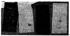
도 3 은 본 발명의 실험예 2에서 실시예 1의 이차전지의 분리막을 찍은 사진이다; 및
도 4 은 본 발명의 실험예 2에서 비교예 1의 이차전지의 분리막을 찍을 사진이다.
<실시예 1>
(a) LiNi0.5Mn1.5O4(양극 활물질) 90 중량%, Super-P(도전제) 5 중량% 및 PVdF(결합제) 5 중량%를 NMP에 첨가하여 양극 합제를 제조한 후, 알루미늄 집전체에 1.2 mAh /cm2의 로딩양으로 도포, 건조 및 압착하여 이차전지용 양극을 제조하였다. Li1.33Ti1.67O4(음극 활물질) 83 중량%, Super-P(도전제) 5 중량% 및 PVdF(결합제) 12 중량%를 NMP에 첨가하여 음극 합제를 제조한 후, 알루미늄 집전체에 1.1 mAh /cm2의 로딩양으로 도포, 건조 및 압착하여 음극을 제조하였다. 에틸렌 카보네이트(EC) : 디메틸 카보네이트(DMC) : 에틸메틸카보네이트(EMC) = 3 : 4 : 3인 용매에 1 M LiPF6를 포함하여 이차전지용 전해액을 제조하였다. 상기 양극과 음극 사이에 폴리프로필렌으로 제조된 다공성 분리막을 게재하여 전극조립체를 제조한 후, 전지케이스 내부에 상기 이차전지용 전해액을 주입한 다음, 밀봉하여 리튬 이차전지를 제조하였다.
(b) 상기 단계(a)에서 전극조립체가 내장되어 있는 전지케이스의 양측면을 3 atm으로 가압하여 전지케이스 내부의 압력을 증가시켰다.
<비교예 1>
실시예 1의 단계(b)에서 전지케이스의 양측면을 가압하지 않은 것을 제외하고는 실시예 1과 동일한 방법으로 리튬 이차전지를 제조하였다.
<실험예 1>
상기 실시예 1 및 비교예 1에서 제조된 리튬 이차전지를 0.5C 충전, 0.5 C 방전 후 레이트 특성을 측정하여 하기 도 1 및 도 2에 각 나타내었다.
하기 도 1에 따르면, 이차 전지 제조과정에서 외부 압력을 가한 실시예 1의 전지는 가스의 발생이 억제되거나 소모되어 전지의 사이클 특성이 일정한 반면, 하기 도 2에 외부 압력을 가하지 않은 비교예 1의 전지는 이차전지 케이스 내부에 존재하는 많은 양의 가스로 인해 사이클 특성이 일정하지 않은 것을 알 수 있다. 이는 외부 압력을 가하는 경우 이차전지 케이스 내부가 고압 상태가 되므로 가스가 발생하는 부반응이 줄어들고, 또한 발생한 가스가 고압 환경하에서 전해액에 용해되어, 용해되지 않은 기체 방울 때문에 일어나는 불균일한 반응이 줄어들기 때문이다.
<실험예 2>
상기 실시예 1 및 비교예 1에서 제조된 리튬 이차전지를 0.5C 충전, 0.5 C 방전 후 전지를 분해하여 분리막을 사진으로 찍어서 하기 도 3 및 도 4에 각각 나타내었다.
하기 도 3에 따르면, 외부 압력을 가한 실시예 1에 따른 전지는 앞서 설명한 이유에서 전지 내부에 존재하는 가스의 양 및 불균일한 반응이 줄어들어 분리막이 균일한 것을 확인할 수 있다. 반면에, 하기 도 4에 따르면, 외부 압력을 가하지 않은 비교예 1에 따른 전지는 전지 내부에 다량의 가스가 존재하여 불균일한 반응이 일어나므로 분리막이 불균일한 것을 알 수 있다.
상기에서 설명하는 바와 같이, 본 발명에 따른 이차전지의 제조 방법은 전극조립체가 내장되어 있는 전지케이스의 양측면을 가압하여 전지케이스 내부의 압력을 증가시킴으로써, 전지의 충방전 과정에서 이산화 탄소를 발생을 억제하는 동시에 이미 발생한 가스를 음극에서 환원되어 소모되도록 할 수 있다.
따라서 전지 내부에 존재하는 다량의 가스로 인해 발생하는 부반응이 줄어들 수 있어 우수한 안전성을 나타내고 레이트 특성 또한, 향상될 수 있다.
Claims (15)
- 전극조립체가 전지케이스의 내부에 밀봉되어 있는 이차전지의 제조 방법으로서,(a) 양극과 음극 사이에 분리막이 개재되어 있는 구조의 전극조립체를 전지케이스의 내부에 전해액과 함께 도입한 후 밀봉하는 단계; 및(b) 단계(a)에서 전극조립체가 내장되어 있는 전지케이스의 양측면을 가압하여 전지케이스 내부의 압력을 증가시킴으로써, 전지의 비정상적인 작동 상태나 고온에서 발생하는 가스를 전지 내부 환경으로부터 제거하는 단계;를 포함하고,상기 전극 조립체는 양극 활물질로 하기 화학식 1로 표시되는 스피넬 구조의 리튬 니켈 망간 복합 산화물을 포함하고, 음극 활물질로 하기 화학식 2로 표시되는 리튬 금속 산화물을 포함하는 것을 특징으로 하는 이차전지의 제조 방법:LixMyMn2-yO4-zAz (1)상기 식에서, 0.9≤x≤1.2, 0<y<2, 0≤z<0.2이고,M은 Al, Mg, Ni, Co, Fe, Cr, V, Ti, Cu, B, Ca, Zn, Zr, Nb, Mo, Sr, Sb, W, Ti 및 Bi로 이루어진 군에서 선택되는 하나 이상의 원소이며;A는 -1 또는 -2가의 하나 이상의 음이온이고;LiaM'bO4-cAc (2)상기 식에서, M'은 Ti, Sn, Cu, Pb, Sb, Zn, Fe, In, Al 및 Zr로 이루어진 군에서 선택되는 하나 이상의 원소이고;a 및 b는 0.1≤a≤4; 0.2≤b≤4의 범위에서 M'의 산화수(oxidation number)에 따라 결정되며;c는 0≤c<0.2의 범위에서 산화수에 따라 결정되고;A는 -1 또는 -2가의 하나 이상의 음이온이다.
- 제 1 항에 있어서, 상기 단계(b)의 가압은 2 atm 내지 10 atm의 크기인 것을 특징으로 하는 이차전지의 제조 방법.
- 제 1 항에 있어서, 상기 단계(b)의 가압은 3 atm 내지 8 atm의 크기인 것을 특징으로 하는 이차전지의 제조 방법.
- 제 1 항에 있어서, 상기 전지케이스는 10 atm의 압력 크기 하에서 사용할 수 있는 것을 특징으로 하는 이차전지의 제조 방법.
- 제 1 항에 있어서, 상기 단계(b)의 가압은 전지케이스의 양 측면에 압착판을 사용하여 수행하는 것을 특징으로 하는 이차전지의 제조 방법.
- 제 1 항에 있어서, 상기 전지케이스는 각형 또는 원통형의 금속 캔으로 이루어진 것을 특징으로 하는 이차전지의 제조 방법.
- 제 1 항에 있어서, 상기 가스는 가압에 의해 음극에서 환원되어 소모되는 것을 특징으로 하는 이차전지의 제조 방법.
- 제 1 항에 있어서, 상기 화학식 1의 산화물은 하기 화학식 3으로 표시되는 것을 특징으로 하는 이차전지의 제조 방법.LixNiyMn2-yO4 (3)상기 식에서, 0.9≤x≤1.2, 0.4≤y≤0.5이다.
- 제 1 항에 있어서, 상기 화학식 1의 산화물은 LiNi0.5Mn1.5O4 또는 LiNi0.4Mn1.6O4인 것을 특징으로 하는 이차전지의 제조 방법.
- 제 1 항에 있어서, 상기 화학식 2의 산화물은 하기 화학식 4로 표시되는 것을 특징으로 하는 이차전지의 제조 방법.LiaTibO4 (4)상기 식에서, 0.5≤a≤3, 1≤b≤2.5 이다.
- 제 1 항에 있어서, 상기 화학식 2의 산화물은 Li1.33Ti1.67O4 또는 LiTi2O4인 것을 특징으로 하는 이차전지의 제조 방법.
- 제 1 항에 따른 제조 방법으로 제조되는 것을 특징으로 하는 이차전지.
- 제 12 항에 있어서, 상기 이차전지의 전지케이스의 내부에 존재하는 가스 양은, 가압이 이루어지지 않은 이차전지의 전지케이스의 내부에 존재하는 가스 전체 중량의 5 내지 60 %인 것을 특징으로 하는 이차전지.
- 제 12 항에 있어서, 상기 이차전지의 전지케이스의 내부의 압력은 내부에 존재하는 가스로 인해 1.2 내지 10 atm인 것을 특징으로 하는 이차전지.
- 제 12 항에 있어서, 상기 이차전지는 리튬 이차전지인 것을 특징으로 하는 이차전지.
Priority Applications (1)
| Application Number | Priority Date | Filing Date | Title |
|---|---|---|---|
| US14/766,018 US10038227B2 (en) | 2013-04-30 | 2014-04-29 | Method of manufacturing secondary battery and secondary battery using the same |
Applications Claiming Priority (2)
| Application Number | Priority Date | Filing Date | Title |
|---|---|---|---|
| KR1020130048047A KR101613101B1 (ko) | 2013-04-30 | 2013-04-30 | 이차전지의 제조 방법 및 이를 이용한 이차전지 |
| KR10-2013-0048047 | 2013-04-30 |
Publications (1)
| Publication Number | Publication Date |
|---|---|
| WO2014178594A1 true WO2014178594A1 (ko) | 2014-11-06 |
Family
ID=51843657
Family Applications (1)
| Application Number | Title | Priority Date | Filing Date |
|---|---|---|---|
| PCT/KR2014/003750 Ceased WO2014178594A1 (ko) | 2013-04-30 | 2014-04-29 | 이차전지의 제조 방법 및 이를 이용한 이차전지 |
Country Status (3)
| Country | Link |
|---|---|
| US (1) | US10038227B2 (ko) |
| KR (1) | KR101613101B1 (ko) |
| WO (1) | WO2014178594A1 (ko) |
Cited By (1)
| Publication number | Priority date | Publication date | Assignee | Title |
|---|---|---|---|---|
| CN116207383A (zh) * | 2023-05-05 | 2023-06-02 | 四川新能源汽车创新中心有限公司 | 锂电池用干法功能层及制备方法和复合电极及制备方法 |
Families Citing this family (2)
| Publication number | Priority date | Publication date | Assignee | Title |
|---|---|---|---|---|
| US10647170B2 (en) * | 2016-03-09 | 2020-05-12 | Maxell Holdings, Ltd. | Tire pressure detection system including air pressure detection device and lithium second battery |
| DE102021101053A1 (de) * | 2021-01-19 | 2022-07-21 | Bayerische Motoren Werke Aktiengesellschaft | Verfahren zum Herstellen eines elektrischen Energiespeichers sowie elektrischer Energiespeicher |
Citations (5)
| Publication number | Priority date | Publication date | Assignee | Title |
|---|---|---|---|---|
| KR20010045712A (ko) * | 1999-11-06 | 2001-06-05 | 김순택 | 리튬망간산화물, 그 제조방법 및 그를 활물질로서채용하는리튬2차전지 |
| JP2002003220A (ja) * | 2000-06-16 | 2002-01-09 | Mitsubishi Chemicals Corp | リチウムイオン二次電池用正極材料、これを用いた正極及び電池 |
| KR20020089649A (ko) * | 2001-05-23 | 2002-11-30 | 삼성에스디아이 주식회사 | 리튬전지의 제조방법 |
| KR20100081455A (ko) * | 2009-01-06 | 2010-07-15 | 주식회사 엘지화학 | 안전성이 향상된 니켈계 양극 활물질 및 이를 포함하는 리튬 이차전지 |
| KR20120043981A (ko) * | 2010-10-27 | 2012-05-07 | 주식회사 엘지화학 | 리튬 과잉의 리튬 망간계 산화물의 제조 방법 및 이를 이용한 리튬 이차전지 |
Family Cites Families (5)
| Publication number | Priority date | Publication date | Assignee | Title |
|---|---|---|---|---|
| JP4742492B2 (ja) * | 2003-10-03 | 2011-08-10 | 日産自動車株式会社 | 電池モジュール、組電池、および、車両 |
| US8481187B2 (en) * | 2009-09-10 | 2013-07-09 | Battelle Memorial Institute | High-energy metal air batteries |
| US20110318651A1 (en) * | 2010-06-24 | 2011-12-29 | Basf Se | Thermoelectric generator |
| JP2012186142A (ja) * | 2011-02-18 | 2012-09-27 | Sumitomo Electric Ind Ltd | 電気化学デバイス用電極およびその製造方法 |
| US9722274B2 (en) * | 2012-06-11 | 2017-08-01 | Nissan Motor Co., Ltd. | Manufacturing method and manufacturing device of secondary battery |
-
2013
- 2013-04-30 KR KR1020130048047A patent/KR101613101B1/ko active Active
-
2014
- 2014-04-29 US US14/766,018 patent/US10038227B2/en active Active
- 2014-04-29 WO PCT/KR2014/003750 patent/WO2014178594A1/ko not_active Ceased
Patent Citations (5)
| Publication number | Priority date | Publication date | Assignee | Title |
|---|---|---|---|---|
| KR20010045712A (ko) * | 1999-11-06 | 2001-06-05 | 김순택 | 리튬망간산화물, 그 제조방법 및 그를 활물질로서채용하는리튬2차전지 |
| JP2002003220A (ja) * | 2000-06-16 | 2002-01-09 | Mitsubishi Chemicals Corp | リチウムイオン二次電池用正極材料、これを用いた正極及び電池 |
| KR20020089649A (ko) * | 2001-05-23 | 2002-11-30 | 삼성에스디아이 주식회사 | 리튬전지의 제조방법 |
| KR20100081455A (ko) * | 2009-01-06 | 2010-07-15 | 주식회사 엘지화학 | 안전성이 향상된 니켈계 양극 활물질 및 이를 포함하는 리튬 이차전지 |
| KR20120043981A (ko) * | 2010-10-27 | 2012-05-07 | 주식회사 엘지화학 | 리튬 과잉의 리튬 망간계 산화물의 제조 방법 및 이를 이용한 리튬 이차전지 |
Cited By (2)
| Publication number | Priority date | Publication date | Assignee | Title |
|---|---|---|---|---|
| CN116207383A (zh) * | 2023-05-05 | 2023-06-02 | 四川新能源汽车创新中心有限公司 | 锂电池用干法功能层及制备方法和复合电极及制备方法 |
| CN116207383B (zh) * | 2023-05-05 | 2023-07-25 | 四川新能源汽车创新中心有限公司 | 锂电池用干法功能层及制备方法和复合电极及制备方法 |
Also Published As
| Publication number | Publication date |
|---|---|
| KR20140129581A (ko) | 2014-11-07 |
| US20160211557A1 (en) | 2016-07-21 |
| KR101613101B1 (ko) | 2016-04-19 |
| US10038227B2 (en) | 2018-07-31 |
Similar Documents
| Publication | Publication Date | Title |
|---|---|---|
| CN106716676B (zh) | 包括增压部的圆柱形电池及其制造方法 | |
| WO2013157883A1 (ko) | 리튬 이차전지용 전해액 및 이를 포함하는 리튬 이차전지 | |
| WO2015016563A1 (ko) | 전해액과 반응을 방지하기 위한 코팅층을 포함하는 전극 | |
| WO2011105833A9 (ko) | 출력 향상을 위한 양극 활물질 및 이를 포함하는 리튬 이차전지 | |
| WO2013122352A1 (ko) | 수계 바인더를 포함하는 음극을 구비한 리튬 이차전지 | |
| WO2012074212A2 (ko) | 전지셀의 제조방법 및 이를 이용하여 생산되는 전지셀 | |
| WO2015016482A1 (ko) | 음극 전극의 전리튬화 방법 | |
| WO2012074219A2 (ko) | 신규한 라미네이션 장치 및 이를 사용하여 생산되는 이차전지 | |
| WO2010093219A2 (ko) | 에너지 밀도가 향상된 리튬이차전지 | |
| WO2013157832A1 (ko) | 리튬 이차전지용 전극의 제조 방법 및 이를 사용하여 제조되는 전극 | |
| WO2013115549A1 (ko) | 지그재그 형상의 실링부를 포함하는 이차전지 | |
| WO2013157867A1 (ko) | 레이트 특성이 향상된 리튬 이차전지 | |
| WO2013157863A1 (ko) | 전극 및 이를 포함하는 이차전지 | |
| WO2014196816A1 (ko) | 신규한 이차전지 | |
| WO2014204185A1 (ko) | 수명 특성이 향상된 리튬 이차전지 | |
| WO2015012640A1 (ko) | 에너지 밀도가 향상된 이차전지용 전극 및 이를 포함하는 리튬 이차전지 | |
| WO2013157811A1 (ko) | 리튬 이차전지용 전극의 제조 방법 및 이를 사용하여 제조되는 전극 | |
| WO2015141997A1 (ko) | 양극 활물질과 이를 포함하는 리튬 이차전지 | |
| WO2015016568A1 (ko) | 안전성이 강화된 리튬 이차전지 | |
| WO2016209014A1 (ko) | 리튬 이차전지의 제조방법 및 이를 사용하여 제조되는 리튬 이차전지 | |
| KR20190044445A (ko) | 리튬 이차전지용 양극 활물질, 이의 제조방법, 이를 포함하는 리튬 이차전지용 양극 및 리튬 이차전지 | |
| WO2013157854A1 (ko) | 성능이 우수한 리튬 이차전지 | |
| WO2013002513A2 (ko) | 향상된 레이트 특성의 이차전지용 양극 활물질 | |
| WO2013157862A1 (ko) | 전극조립체 및 이를 포함하는 리튬 이차전지 | |
| WO2019017617A1 (ko) | 집전체가 없는 전극 및 이를 포함하는 이차전지 |
Legal Events
| Date | Code | Title | Description |
|---|---|---|---|
| 121 | Ep: the epo has been informed by wipo that ep was designated in this application |
Ref document number: 14792143 Country of ref document: EP Kind code of ref document: A1 |
|
| WWE | Wipo information: entry into national phase |
Ref document number: 14766018 Country of ref document: US |
|
| NENP | Non-entry into the national phase |
Ref country code: DE |
|
| 122 | Ep: pct application non-entry in european phase |
Ref document number: 14792143 Country of ref document: EP Kind code of ref document: A1 |