WO2014175269A1 - ディーゼルエンジン - Google Patents
ディーゼルエンジン Download PDFInfo
- Publication number
- WO2014175269A1 WO2014175269A1 PCT/JP2014/061293 JP2014061293W WO2014175269A1 WO 2014175269 A1 WO2014175269 A1 WO 2014175269A1 JP 2014061293 W JP2014061293 W JP 2014061293W WO 2014175269 A1 WO2014175269 A1 WO 2014175269A1
- Authority
- WO
- WIPO (PCT)
- Prior art keywords
- atmospheric pressure
- exhaust gas
- diesel engine
- passage
- egr
- Prior art date
- Legal status (The legal status is an assumption and is not a legal conclusion. Google has not performed a legal analysis and makes no representation as to the accuracy of the status listed.)
- Ceased
Links
Images


Classifications
-
- F—MECHANICAL ENGINEERING; LIGHTING; HEATING; WEAPONS; BLASTING
- F02—COMBUSTION ENGINES; HOT-GAS OR COMBUSTION-PRODUCT ENGINE PLANTS
- F02D—CONTROLLING COMBUSTION ENGINES
- F02D41/00—Electrical control of supply of combustible mixture or its constituents
- F02D41/02—Circuit arrangements for generating control signals
- F02D41/04—Introducing corrections for particular operating conditions
- F02D41/06—Introducing corrections for particular operating conditions for engine starting or warming up
- F02D41/062—Introducing corrections for particular operating conditions for engine starting or warming up for starting
-
- F—MECHANICAL ENGINEERING; LIGHTING; HEATING; WEAPONS; BLASTING
- F02—COMBUSTION ENGINES; HOT-GAS OR COMBUSTION-PRODUCT ENGINE PLANTS
- F02D—CONTROLLING COMBUSTION ENGINES
- F02D41/00—Electrical control of supply of combustible mixture or its constituents
- F02D41/0025—Controlling engines characterised by use of non-liquid fuels, pluralities of fuels, or non-fuel substances added to the combustible mixtures
- F02D41/0047—Controlling exhaust gas recirculation [EGR]
- F02D41/005—Controlling exhaust gas recirculation [EGR] according to engine operating conditions
- F02D41/0055—Special engine operating conditions, e.g. for regeneration of exhaust gas treatment apparatus
-
- F—MECHANICAL ENGINEERING; LIGHTING; HEATING; WEAPONS; BLASTING
- F02—COMBUSTION ENGINES; HOT-GAS OR COMBUSTION-PRODUCT ENGINE PLANTS
- F02D—CONTROLLING COMBUSTION ENGINES
- F02D21/00—Controlling engines characterised by their being supplied with non-airborne oxygen or other non-fuel gas
- F02D21/06—Controlling engines characterised by their being supplied with non-airborne oxygen or other non-fuel gas peculiar to engines having other non-fuel gas added to combustion air
- F02D21/08—Controlling engines characterised by their being supplied with non-airborne oxygen or other non-fuel gas peculiar to engines having other non-fuel gas added to combustion air the other gas being the exhaust gas of engine
- F02D2021/083—Controlling engines characterised by their being supplied with non-airborne oxygen or other non-fuel gas peculiar to engines having other non-fuel gas added to combustion air the other gas being the exhaust gas of engine controlling exhaust gas recirculation electronically
-
- F—MECHANICAL ENGINEERING; LIGHTING; HEATING; WEAPONS; BLASTING
- F02—COMBUSTION ENGINES; HOT-GAS OR COMBUSTION-PRODUCT ENGINE PLANTS
- F02D—CONTROLLING COMBUSTION ENGINES
- F02D2200/00—Input parameters for engine control
- F02D2200/70—Input parameters for engine control said parameters being related to the vehicle exterior
- F02D2200/703—Atmospheric pressure
-
- F—MECHANICAL ENGINEERING; LIGHTING; HEATING; WEAPONS; BLASTING
- F02—COMBUSTION ENGINES; HOT-GAS OR COMBUSTION-PRODUCT ENGINE PLANTS
- F02D—CONTROLLING COMBUSTION ENGINES
- F02D41/00—Electrical control of supply of combustible mixture or its constituents
- F02D41/0025—Controlling engines characterised by use of non-liquid fuels, pluralities of fuels, or non-fuel substances added to the combustible mixtures
- F02D41/0047—Controlling exhaust gas recirculation [EGR]
- F02D41/0065—Specific aspects of external EGR control
-
- Y—GENERAL TAGGING OF NEW TECHNOLOGICAL DEVELOPMENTS; GENERAL TAGGING OF CROSS-SECTIONAL TECHNOLOGIES SPANNING OVER SEVERAL SECTIONS OF THE IPC; TECHNICAL SUBJECTS COVERED BY FORMER USPC CROSS-REFERENCE ART COLLECTIONS [XRACs] AND DIGESTS
- Y02—TECHNOLOGIES OR APPLICATIONS FOR MITIGATION OR ADAPTATION AGAINST CLIMATE CHANGE
- Y02T—CLIMATE CHANGE MITIGATION TECHNOLOGIES RELATED TO TRANSPORTATION
- Y02T10/00—Road transport of goods or passengers
- Y02T10/10—Internal combustion engine [ICE] based vehicles
- Y02T10/40—Engine management systems
Definitions
- the present invention relates to the technology of a diesel engine.
- a diesel engine is known as one of internal combustion engines.
- diesel engines have a high pressure in the combustion chamber and take in excess air, so that a large amount of nitrogen oxide (NOx) is generated. Therefore, an exhaust gas recirculation device is provided in the diesel engine to reduce NOx (for example, Japanese Utility Model Publication No. 02-43447).
- An exhaust gas recirculation device opens and closes an exhaust gas recirculation passage communicating between an exhaust passage and an intake passage by an exhaust gas recirculation valve, and recirculates part of the exhaust gas from the exhaust passage to the intake passage via the exhaust gas recirculation passage It is.
- the exhaust gas recirculation device the exhaust gas after combustion, which does not contain oxygen or is in a lean state, is mixed with the intake air, the oxygen concentration in the intake air is lowered, and the oxygen concentration is lower than the atmosphere. Combustion is performed, the combustion temperature is lowered, and the generation of NOx is suppressed.
- Patent Document 1 discloses a configuration for correcting and controlling the opening degree of the exhaust gas recirculation valve based on a signal from an atmospheric pressure sensor, but does not disclose specific control means. Therefore, a diesel engine equipped with an exhaust gas recirculation device requires specific control means for preventing the generation of black smoke at high altitudes.
- the problem to be solved by the present invention is to provide a diesel engine that can prevent the generation of black smoke at high altitudes.
- an exhaust gas recirculation passage communicating between the exhaust passage and the intake air passage is opened and closed by an exhaust gas recirculation valve, and a part of the exhaust gas passes from the exhaust passage to the intake passage via the exhaust gas recirculation passage.
- the control device when the atmospheric pressure detecting means is abnormal, the control device, even if the atmospheric pressure detected by the atmospheric pressure detecting means is not more than a predetermined pressure after the start is completed, It does not block the recirculation of the exhaust gas recirculation device.
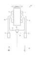
- the schematic diagram which shows the whole structure of a diesel engine.
- the flowchart which shows the flow of EGR cut control.
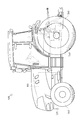
- time chart The side view which shows the whole structure of a tractor.
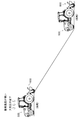
- the schematic diagram which shows the tractor which travels at a high altitude.
- the diesel engine 100 will be described with reference to FIG. In addition, in FIG. 1, the diesel engine 100 is represented typically. Moreover, the broken line of FIG. 1 represents the electric signal line.
- the diesel engine 100 is an embodiment according to the diesel engine of the present invention.
- the diesel engine 100 includes a crankshaft 5, a cylinder block (not shown) that supports the crankshaft 5, a cylinder head 6 provided on the cylinder block, an intake passage 10, an exhaust passage 20, and an exhaust gas recycle.
- EGR (Exhaust Gas Recirculation) device 30 as a circulation device
- ECU (Engine Control Unit) 50 as a control device
- an atmospheric pressure sensor 60 as an atmospheric pressure detection means
- a fuel injection device (not shown), etc. is doing.
- An intake manifold 11 is provided on one side of the cylinder head 6. One end of an intake passage 10 is communicated with the intake manifold 11, and an air cleaner 12 is provided at the other end of the intake passage 10. That is, the intake passage 10 communicates between the intake manifold 11 and the air cleaner 12.
- An exhaust manifold 21 is provided on the other side of the cylinder head 6.
- One end of an exhaust passage 20 is communicated with the exhaust manifold 21, and a muffler 22 is communicated with the other end of the exhaust passage 20. That is, the exhaust passage 20 communicates between the exhaust manifold 21 and the muffler 22.
- the EGR device 30 returns a part of the exhaust gas from the exhaust passage 20 to the intake passage 10. Specifically, the EGR device 30 suppresses the generation of nitrogen oxides by lowering the oxygen concentration in the intake air and gradually burning the fuel.
- the EGR device 30 includes an EGR passage 31 that is an exhaust recirculation passage that communicates between the exhaust passage 20 and the intake passage 10, and an EGR valve 32 that is an exhaust recirculation valve that opens and closes the EGR passage 31. .
- the EGR valve 32 is connected to the ECU 50.
- the ECU 50 controls the operation of the diesel engine 100.
- An EGR valve 32 and an atmospheric pressure sensor 60 are connected to the ECU 50.
- the ECU 50 has a function of determining atmospheric pressure by an atmospheric pressure sensor 60 described later.
- the ECU 50 has a function of adjusting a degree of opening of the EGR valve 32 of the EGR device 30 and returning a part of the exhaust gas from the exhaust passage 20 to the intake passage 10 (EGR control).
- the atmospheric pressure sensor 60 measures atmospheric pressure.
- the atmospheric pressure sensor 60 is connected to the ECU 50.
- the flow of the EGR cut control S100 will be described with reference to FIG. In FIG. 2, the flow of the EGR cut control S100 is schematically represented by a flowchart.
- the EGR cut control S100 is a control for interrupting the reflux of the EGR device when the atmospheric pressure detected by the atmospheric pressure sensor 60 is equal to or lower than a predetermined pressure after the start of the diesel engine 100 is completed.
- step S110 the ECU 50 completes starting the diesel engine 100. Specifically, starting by the starter (cell motor) is completed, and driving of the diesel engine 100 is started.
- step S120 the ECU 50 opens the EGR valve 32 of the EGR device 30 and recirculates a part of the exhaust gas from the exhaust passage 20 to the intake passage 10 (EGR control).
- EGR control the opening degree of the EGR valve 32 is adjusted based on the engine speed and the engine load. However, in this embodiment, the description of the opening degree adjustment of the EGR valve 32 is omitted.
- step S130 the ECU 50 confirms whether the atmospheric pressure sensor 60 is normal. Specifically, the ECU 50 energizes the atmospheric pressure sensor 60, and determines that it is normal if energized. On the other hand, when it cannot energize, it judges that it is abnormal by disconnection or sensor failure. If the atmospheric pressure sensor 60 is normal, the ECU 50 proceeds to step S140. On the other hand, if the atmospheric pressure sensor 60 is abnormal, the ECU 50 proceeds to step S170.
- step S140 the ECU 50 measures the atmospheric pressure by the atmospheric pressure sensor 60.
- step S150 the ECU 50 confirms whether or not the atmospheric pressure measured in step S140 is equal to or lower than a predetermined atmospheric pressure. Specifically, the ECU 50 confirms whether the current position of the diesel engine 100 is high or low based on the measured atmospheric pressure. If the measured atmospheric pressure is equal to or lower than the predetermined atmospheric pressure, that is, if the current position is highland, the ECU 50 proceeds to step S160. On the other hand, if the measured atmospheric pressure is greater than the predetermined atmospheric pressure, that is, if the current position is low, the ECU 50 proceeds to step S170.
- step S160 the ECU 50 closes the EGR valve 32 of the EGR device 30 and blocks recirculation of a part of the exhaust gas from the exhaust passage 20 to the intake passage 10.
- step S170 the EGR valve 32 of the EGR device 30 is opened as it is, and a part of the exhaust gas is recirculated from the exhaust passage 20 to the intake passage 10 (EGR control).
- the EGR cut control S100 is control at the start of engine start, and does not operate during engine operation. For example, it is assumed that the EGR cut control S100 is not executed even when there is a change in atmospheric pressure during engine operation.
- the tractor 500 is set.
- the EGR cut control S100 is configured not to operate even when reciprocating between 1180 m and 1220 m above sea level (see FIG. 5).
- the flow of the EGR cut control S100 will be described with reference to FIG. In FIG. 3, the flow of the EGR cut control S100 is schematically represented by a time chart.
- the starter (cell motor) starts the engine. Further, when the key switch is set to START, the start of the engine is completed by the starter (cell motor), and engine driving is started.
- the atmospheric pressure is measured by the atmospheric pressure sensor 60.
- the atmospheric pressure is measured by the atmospheric pressure sensor 60 for 4 seconds.
- the EGR valve 32 of the EGR device 30 is opened and a part of the exhaust gas is recirculated from the exhaust passage 20 to the intake passage 10 (EGR control).
- the EGR control is interrupted when the current position is determined to be a high altitude by the measured atmospheric pressure.
- the EGR control is continued.
- the effect of the diesel engine 100 will be described. According to the diesel engine 100, generation of black smoke at high altitudes can be prevented.
- the atmospheric pressure is measured by the atmospheric pressure sensor 60, and when it is determined that the current position is a highland based on the measured atmospheric pressure, EGR Since the control is interrupted, the generation of black smoke at high altitudes can be prevented.
- tractor 500 which is embodiment of the diesel engine 100 which concerns on this invention using FIG. 4 and FIG. 5 is demonstrated.
- the tractor 500 is shown in a side view.
- the tractor 500 is equipped with various working machines (such as a rotary) and performs various operations using the worn working machines.
- the tractor 500 is configured such that the body frame 520 is arranged with the longitudinal direction as the front-rear direction, and is connected to the diesel engine 100 at the rear part.
- a transmission case 540 that houses a part of the power transmission mechanism of the tractor 500 is connected to the rear portion of the diesel engine 100 with the longitudinal direction being the front-rear direction.
- the front part of the body frame 520 is supported by a pair of left and right front wheels 550 via a front axle
- the rear part of the transmission case 540 is supported by a pair of left and right rear wheels 560 via a rear axle.
- FIG. 5 schematically shows a tractor 500 that travels at a high altitude.
- the tractor 500 is mounted with a rotary 600 that is a working machine.
- the atmospheric pressure corresponding to the lowland acts on the tractor 500 traveling in the lowland, that is, the normal tractor 500.
- an air pressure smaller than the atmospheric pressure in the lowland is acting on the tractor 500 that travels in a highland such as a mountainous area.
- the oxygen concentration in the atmosphere is low.
- the EGR cut control S100 does not operate even if the tractor 500 works by reciprocating between 1080 m and 1120 m above sea level. That is, even if the tractor 500 is traveling at an altitude near the reference pressure, the EGR cut control S100 does not operate frequently. Therefore, the operation of the diesel engine 100 does not become unstable due to the hunting of the EGR valve 32 of the EGR device 30, and the operator does not feel uncomfortable.
- the present invention can be used for tractors.
- Intake passage 20 Exhaust passage 30 EGR device (exhaust gas circulation device) 50 ECU (control device) 60 atmospheric pressure sensor (atmospheric pressure detection means) 100 diesel engine
Landscapes
- Engineering & Computer Science (AREA)
- Chemical & Material Sciences (AREA)
- Combustion & Propulsion (AREA)
- Mechanical Engineering (AREA)
- General Engineering & Computer Science (AREA)
- Exhaust-Gas Circulating Devices (AREA)
- Combined Controls Of Internal Combustion Engines (AREA)
- Output Control And Ontrol Of Special Type Engine (AREA)
Abstract
Description
ンを提供することである。
なお、図1では、ディーゼルエンジン100を模式的に表している。また、図1の破線は、電気信号線を表している。
なお、図2では、EGRカット制御S100の流れをフローチャートによって模式的に表している。
なお、図3では、EGRカット制御S100の流れをタイムチャートによって模式的に表している。
ディーゼルエンジン100によれば、高地での黒煙の発生を防止できる。
なお、図4では、トラクタ500を側面視にて表している。
なお、図5では、高地走行するトラクタ500を模式的に表している。また、図5では、トラクタ500に作業機であるロータリ600が装着されている。
20 排気通路
30 EGR装置(排気ガス循環装置)
50 ECU(制御装置)
60 大気圧センサ(大気圧検出手段)
100 ディーゼルエンジン
Claims (2)
- 排気通路と吸気通路との間を連通する排気還流通路を排気還流弁によって開閉し、該排気還流通路を介して前記排気通路から前記吸気通路に排気ガスの一部を還流する排気ガス再循環装置と、該排気ガス循環装置の還流を制御する制御装置と、を備えるディーゼルエンジンであって、
大気圧を検出する大気圧検出手段を備え、
前記制御装置は、始動完了後に、前記大気圧検出手段が検出する大気圧が所定圧以下であれば、前記排気ガス再循環装置の還流を遮断する、ディーゼルエンジン。 - 請求項1記載のディーゼルエンジンであって、
前記制御装置は、前記大気圧検出手段が異常である場合には、始動完了後に、前記大気圧検出手段が検出する大気圧が所定圧以下であっても、前記排気ガス再循環装置の還流を遮断しない、ディーゼルエンジン。
Priority Applications (2)
| Application Number | Priority Date | Filing Date | Title |
|---|---|---|---|
| CN201480023414.4A CN105143654B (zh) | 2013-04-23 | 2014-04-22 | 柴油发动机 |
| KR1020157032104A KR101788718B1 (ko) | 2013-04-23 | 2014-04-22 | 디젤 엔진 |
Applications Claiming Priority (2)
| Application Number | Priority Date | Filing Date | Title |
|---|---|---|---|
| JP2013-090811 | 2013-04-23 | ||
| JP2013090811A JP6058461B2 (ja) | 2013-04-23 | 2013-04-23 | ディーゼルエンジン |
Publications (1)
| Publication Number | Publication Date |
|---|---|
| WO2014175269A1 true WO2014175269A1 (ja) | 2014-10-30 |
Family
ID=51791841
Family Applications (1)
| Application Number | Title | Priority Date | Filing Date |
|---|---|---|---|
| PCT/JP2014/061293 Ceased WO2014175269A1 (ja) | 2013-04-23 | 2014-04-22 | ディーゼルエンジン |
Country Status (4)
| Country | Link |
|---|---|
| JP (1) | JP6058461B2 (ja) |
| KR (1) | KR101788718B1 (ja) |
| CN (1) | CN105143654B (ja) |
| WO (1) | WO2014175269A1 (ja) |
Families Citing this family (1)
| Publication number | Priority date | Publication date | Assignee | Title |
|---|---|---|---|---|
| WO2022219765A1 (ja) | 2021-04-15 | 2022-10-20 | 日産自動車株式会社 | 内燃機関の制御方法および制御装置 |
Citations (4)
| Publication number | Priority date | Publication date | Assignee | Title |
|---|---|---|---|---|
| JPS597254U (ja) * | 1982-07-07 | 1984-01-18 | トヨタ自動車株式会社 | 内燃機関の排気ガス再循環制御装置 |
| JPS6181568A (ja) * | 1984-09-11 | 1986-04-25 | Honda Motor Co Ltd | 内燃エンジンの排気還流制御方法 |
| JPH06167236A (ja) * | 1992-11-30 | 1994-06-14 | Mazda Motor Corp | 圧力センサの故障検出装置 |
| JP2011043152A (ja) * | 2009-08-24 | 2011-03-03 | Daihatsu Motor Co Ltd | 制御装置 |
Family Cites Families (7)
| Publication number | Priority date | Publication date | Assignee | Title |
|---|---|---|---|---|
| JPH0243447A (ja) | 1988-07-30 | 1990-02-14 | Sanko Metal Ind Co Ltd | 二重折板屋根 |
| JPH0243447U (ja) * | 1988-09-19 | 1990-03-26 | ||
| JPH06101525A (ja) * | 1992-09-18 | 1994-04-12 | Toyota Motor Corp | ディーゼルエンジンの燃料噴射量制御装置 |
| JPH0960559A (ja) * | 1995-08-24 | 1997-03-04 | Toyota Autom Loom Works Ltd | 内燃機関の高度補償装置 |
| JP3183218B2 (ja) * | 1997-06-10 | 2001-07-09 | トヨタ自動車株式会社 | 内燃機関の制御装置 |
| JP5907339B2 (ja) * | 2011-05-27 | 2016-04-26 | 株式会社デンソー | 内燃機関の筒内流入egrガス流量推定装置 |
| JP5854328B2 (ja) * | 2011-05-27 | 2016-02-09 | 株式会社デンソー | 内燃機関の制御装置 |
-
2013
- 2013-04-23 JP JP2013090811A patent/JP6058461B2/ja active Active
-
2014
- 2014-04-22 KR KR1020157032104A patent/KR101788718B1/ko active Active
- 2014-04-22 WO PCT/JP2014/061293 patent/WO2014175269A1/ja not_active Ceased
- 2014-04-22 CN CN201480023414.4A patent/CN105143654B/zh active Active
Patent Citations (4)
| Publication number | Priority date | Publication date | Assignee | Title |
|---|---|---|---|---|
| JPS597254U (ja) * | 1982-07-07 | 1984-01-18 | トヨタ自動車株式会社 | 内燃機関の排気ガス再循環制御装置 |
| JPS6181568A (ja) * | 1984-09-11 | 1986-04-25 | Honda Motor Co Ltd | 内燃エンジンの排気還流制御方法 |
| JPH06167236A (ja) * | 1992-11-30 | 1994-06-14 | Mazda Motor Corp | 圧力センサの故障検出装置 |
| JP2011043152A (ja) * | 2009-08-24 | 2011-03-03 | Daihatsu Motor Co Ltd | 制御装置 |
Also Published As
| Publication number | Publication date |
|---|---|
| KR101788718B1 (ko) | 2017-10-20 |
| CN105143654A (zh) | 2015-12-09 |
| CN105143654B (zh) | 2017-07-04 |
| KR20150142017A (ko) | 2015-12-21 |
| JP6058461B2 (ja) | 2017-01-11 |
| JP2014214639A (ja) | 2014-11-17 |
Similar Documents
| Publication | Publication Date | Title |
|---|---|---|
| JP5681813B2 (ja) | 内燃機関の吸気制御装置 | |
| KR102274486B1 (ko) | 엔진 작동 장치 | |
| US10907592B2 (en) | Vaporized fuel treatment device and learning method of valve opening start position of sealing valve in vaporized fuel treatment device | |
| JP5176742B2 (ja) | ハイブリッド自動車の制御方法及びその装置 | |
| JP6058461B2 (ja) | ディーゼルエンジン | |
| US10151261B2 (en) | Stop control system for direct-injection type internal combustion engine | |
| KR101926927B1 (ko) | Ffv의 엔진 시동 제어 방법 | |
| JP2007218247A (ja) | 内燃機関の排気浄化装置 | |
| JP3677953B2 (ja) | 内燃機関の燃料供給制御装置 | |
| JP4895951B2 (ja) | ディーゼルエンジンの制御装置 | |
| JP2015017518A (ja) | 内燃機関の制御装置および制御方法 | |
| JP5146560B2 (ja) | 内燃機関の排気浄化装置 | |
| JP4883321B2 (ja) | 内燃機関の制御装置 | |
| JP2007137321A (ja) | ハイブリッド車両の内燃機関制御装置 | |
| JP2006299858A (ja) | 車両の制御装置 | |
| JP4924444B2 (ja) | 内燃機関の制御装置および制御方法 | |
| JP4196897B2 (ja) | 水素添加内燃機関の制御装置 | |
| JP6166646B2 (ja) | 内燃機関の制御装置 | |
| JP4980943B2 (ja) | 燃料流量算出装置 | |
| KR102930672B1 (ko) | 하이브리드 차량을 동작시키는 방법 및 디바이스 | |
| JP2010163940A (ja) | 内燃機関のブローバイガス還流装置 | |
| JP2007016655A (ja) | 内燃機関の排気浄化装置 | |
| JP2017166465A (ja) | パージ処理装置 | |
| EP2530289A2 (en) | Activation determining system for oxygen sensor | |
| JP2017122405A (ja) | エンジン制御装置 |
Legal Events
| Date | Code | Title | Description |
|---|---|---|---|
| WWE | Wipo information: entry into national phase |
Ref document number: 201480023414.4 Country of ref document: CN |
|
| 121 | Ep: the epo has been informed by wipo that ep was designated in this application |
Ref document number: 14788562 Country of ref document: EP Kind code of ref document: A1 |
|
| NENP | Non-entry into the national phase |
Ref country code: DE |
|
| ENP | Entry into the national phase |
Ref document number: 20157032104 Country of ref document: KR Kind code of ref document: A |
|
| 122 | Ep: pct application non-entry in european phase |
Ref document number: 14788562 Country of ref document: EP Kind code of ref document: A1 |