WO2014171209A1 - 多段遠心流体機械 - Google Patents
多段遠心流体機械 Download PDFInfo
- Publication number
- WO2014171209A1 WO2014171209A1 PCT/JP2014/055546 JP2014055546W WO2014171209A1 WO 2014171209 A1 WO2014171209 A1 WO 2014171209A1 JP 2014055546 W JP2014055546 W JP 2014055546W WO 2014171209 A1 WO2014171209 A1 WO 2014171209A1
- Authority
- WO
- WIPO (PCT)
- Prior art keywords
- inner barrel
- casing
- fluid machine
- barrel
- centrifugal fluid
- Prior art date
Links
Images


Classifications
-
- F—MECHANICAL ENGINEERING; LIGHTING; HEATING; WEAPONS; BLASTING
- F04—POSITIVE - DISPLACEMENT MACHINES FOR LIQUIDS; PUMPS FOR LIQUIDS OR ELASTIC FLUIDS
- F04D—NON-POSITIVE-DISPLACEMENT PUMPS
- F04D17/00—Radial-flow pumps, e.g. centrifugal pumps; Helico-centrifugal pumps
- F04D17/08—Centrifugal pumps
- F04D17/10—Centrifugal pumps for compressing or evacuating
- F04D17/12—Multi-stage pumps
- F04D17/122—Multi-stage pumps the individual rotor discs being, one for each stage, on a common shaft and axially spaced, e.g. conventional centrifugal multi- stage compressors
-
- F—MECHANICAL ENGINEERING; LIGHTING; HEATING; WEAPONS; BLASTING
- F04—POSITIVE - DISPLACEMENT MACHINES FOR LIQUIDS; PUMPS FOR LIQUIDS OR ELASTIC FLUIDS
- F04D—NON-POSITIVE-DISPLACEMENT PUMPS
- F04D29/00—Details, component parts, or accessories
- F04D29/40—Casings; Connections of working fluid
- F04D29/42—Casings; Connections of working fluid for radial or helico-centrifugal pumps
- F04D29/4206—Casings; Connections of working fluid for radial or helico-centrifugal pumps especially adapted for elastic fluid pumps
-
- F—MECHANICAL ENGINEERING; LIGHTING; HEATING; WEAPONS; BLASTING
- F04—POSITIVE - DISPLACEMENT MACHINES FOR LIQUIDS; PUMPS FOR LIQUIDS OR ELASTIC FLUIDS
- F04D—NON-POSITIVE-DISPLACEMENT PUMPS
- F04D29/00—Details, component parts, or accessories
- F04D29/60—Mounting; Assembling; Disassembling
- F04D29/62—Mounting; Assembling; Disassembling of radial or helico-centrifugal pumps
- F04D29/624—Mounting; Assembling; Disassembling of radial or helico-centrifugal pumps especially adapted for elastic fluid pumps
Definitions
- the present invention relates to a multistage centrifugal fluid machine such as a pump or a compressor, and more particularly to a fastening / holding structure for an inner barrel of the multistage centrifugal machine.
- Patent Document 1 Examples of conventional single-shaft multi-stage centrifugal compressors are described in Patent Document 1 and Non-Patent Document 1.
- the centrifugal compressor described in Patent Document 1 has an inner barrel type casing, and an annular groove is formed on the inner peripheral surface of the casing and in the vicinity of the end portion in the axial direction.
- a stepped portion is formed on the outer periphery of the head cover that closes the axial end surface of the casing.
- the first shear key is engaged with both the groove portion of the casing and the stepped portion of the head cover, and the second shear key disposed adjacent to the first shear key is engaged with the groove of the casing. Yes.
- the first and second shear keys are each divided into a plurality of circumferential directions, and each divided member is fixed to the casing in the radial direction but is not fastened to each other in the axial direction. Further, a shear force acts between the first shear key member and the second shear key member, but slight displacement of each divided member due to the shear force is allowed in the radial direction.
- Patent Document 2 An example of a conventional turbomachine is described in Patent Document 2.
- a stator including an inner casing and a rotor including an impeller and a rotating shaft are accommodated on the inner peripheral side of a cylindrical outer casing whose both side surfaces are open. Both shaft end surfaces are closed by a closing member. At that time, the closing member is held in the casing by the shear key. Furthermore, an annular groove is formed on the inner side surface of the closing member, and an annular protrusion formed on the side surface of the inner casing and an annular protrusion formed on the inner peripheral side surface of the outer casing in the annular groove. Is engaged.
- each component held inside the barrel casing is set to have a strength and thickness that can withstand the working pressure. Therefore, in each of the above prior art documents, the axial thickness of each component is manufactured within a predetermined manufacturing error, and each component is housed inside the barrel-type casing in a state of being assembled without any gap in the axial direction.
- the stator part including the assembled inner casing and the rotor part including the impeller and the rotating shaft absorb the manufacturing error of each part by the shear key part and are locked to the barrel type outer casing, and can withstand deformation at high pressure. I am doing so.
- the share key in this way makes the structure itself relatively simple. However, since it is necessary to absorb the manufacturing error of each part by the share key part, after measuring the manufacturing error in the assembled state for each part accommodated in the barrel type outer casing, the predetermined dimension correcting part Is processed so that the axial clearance in the shear key portion is about 0.1 mm or less.
- the present invention has been made in view of the above-mentioned problems of the prior art, and its purpose is to determine the axial positioning at the shear key portion when a shear key is used in a barrel type casing in a high-pressure single-shaft multi-stage fluid machine. Therefore, secondary processing is not required.
- a feature of the present invention that achieves the above object is that a multistage centrifugal fluid machine has a rotor formed by attaching a plurality of impellers to a rotating shaft, and is fitted to a cylindrical outer casing and the outer casing.
- Each of the group inner barrels is fastened with tie bolts provided at multiple locations in the circumferential direction. Together it is, lies in the connection between the groove provided on the outer periphery of each of a plurality of connecting members.
- the connecting member has a cross-sectional shape and is fixed to a groove formed in one inner barrel of the first and second group inner barrels, and a shaft formed in the groove formed in the other inner barrel. It is desirable to fit with a gap in the direction, and the size of the gap is preferably equal to or larger than the axial production error of the inner casing.
- the outer barrel has at least two steps, one of the steps is formed in a portion that fits the driving side head flange, and the other step is formed as a first-stage suction flow path of the multistage centrifugal compressor.
- the inner barrel may be formed in the vicinity of the inner barrel, and a step corresponding to the two steps of the outer barrel may be formed on the driving side head flange and the inner barrel so that the inner barrel can be fitted into the step of the outer barrel.
- a vane-shaped spacer may be provided corresponding to the tie bolt in a portion where the tie bolt crosses the suction flow path of the compressor, and a hole through which the tie bolt passes may be formed in the spacer.
- the inner casings accommodated in the barrel type casing are grouped into two groups in the axial direction, and each group is manufactured in the axial direction. Positioning in the axial direction is facilitated because the connecting members that are fitted with a gap larger than the error are arranged. Further, secondary processing for axial positioning is not required at the share key portion.
- FIG. 5 is a detailed view of part C in FIG. 4.
- FIG. 6 is a cross-sectional view taken along line EE in FIG. 5.
- FIG. 5 is a detailed view of a D part in FIG. 4.
- FIG. 1 is a longitudinal sectional view of a single-shaft multistage centrifugal compressor 200 having a barrel-type casing 10.
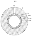
- 2 is a cross-sectional view taken along the arrow A in FIG. 1 and excluding the rotor 3 part
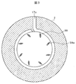
- FIG. 3 is a cross-sectional view taken along the arrow B in FIG. 1 and excluding the rotor 3 part.
- FIG. 4 is an enlarged detail view of the main part of FIG.
- a plurality of (five in the figure) impellers 41 to 81 are attached to the rotary shaft 30, and these constitute the rotor 3.
- a pair of radial bearings 31 and 32 are disposed at both shaft end portions of the rotating shaft 30, and a thrust bearing 36 is disposed further on the shaft end side of the one radial bearing 31.
- the radial bearings 31 and 32 support the rotary shaft 30 so as to be rotatable.
- the thrust bearing 36 supports a thrust load applied to the rotor 3.
- the first and second stage impellers 41 and 51 and the third to final stage impellers 61 to 81 are provided on the back of the core plate. It is a back-facing type that faces each other. Further, the shaft end side of the thrust bearing 36 is covered with a cover 37.
- Sealing means 34 and 35 are disposed between the impellers 41 to 81 and the radial bearings 31 and 32 in order to prevent the working gas compressed in the rotor 3 from being pressurized to leak outside. Yes. Sealing gas is supplied to the sealing means 34 and 35 from the outside by a gas sealing means (not shown).
- the casing 10 of the multistage centrifugal compressor 200 is a double cylinder type casing, and has an inner casing 1 and an outer barrel 2.
- the outer barrel 2 has a suction flow path 17a for supplying a working gas from a suction nozzle (not shown) to the first stage impeller 41, and a discharge nozzle (not shown) from the final stage impeller 81.
- a discharge passage 17d for discharging compressed gas to the outside is formed.
- a discharge flow path 17c for temporarily taking out the intermediate stage compressed gas and cooling it, and a suction flow path 17b for returning it to the compressor 200 are also provided. Is formed.
- FIG. 2 shows the suction flow path 17b of the intermediate stage compressor 60 in a cross-sectional view.
- the suction flow path 17a of the first stage compressor 40 has the same configuration.
- FIG. 3 is a cross-sectional view of the discharge flow path 17c of the intermediate stage compressor 70.
- the discharge flow path 17d of the final stage compressor 80 has the same configuration.
- the channels 17a to 17d are formed in a hole shape that penetrates the outer barrel 2 in the radial direction.
- the outer barrel 2 is a cylindrical casing having a stepped inner surface.
- the inner casing 1 forms a working gas flow path of the multistage centrifugal compressor 200 together with the rotor 3.
- a thrust side head flange 12 that forms a suction flow path 18a to the first stage impeller 41, and a drive side head flange 11 that forms a suction flow path 18b to the intermediate stage impeller are arranged on both shaft end portions.
- an inner barrel 4 called a bundle is disposed between the two head flanges 11 and 12 in order to form a flow path for guiding the flow leaving the impeller to the next stage impeller.
- the inner barrel 4 has a horizontally divided shape, and each horizontally divided inner barrel 4 is divided into a plurality of portions in the axial direction.
- the inner barrel 4 is divided into two groups between the impellers facing each other, and each group is integrated by tie bolts 141 and 143.
- a stepped portion 12a is formed at the outer peripheral portion of the thrust side head flange 12 of the inner casing 1 and at the outer end portion of the machine.
- a groove portion 14b is formed on the inner peripheral surface of the outer barrel 2 on the thrust side.
- Arc-shaped first and second shear keys 21 and 22 are engaged with the groove portion 14b and the stepped portion 12a at a plurality of locations in the circumferential direction.
- the second shear key 22 is locked to both the groove portion 14b and the stepped portion 12a.
- the first shear key 21 connected to the second shear key 22 has a stepped shape and is locked to the corner portion 14a of the groove portion 14b of the outer barrel 2 by the stepped portion 21a.
- a stepped portion is formed on the inner peripheral side of the driving side portion of the outer barrel 2 and in the vicinity of the suction flow path 18a of the first stage compressor.
- a stepped portion 13d on the drive side of the outer barrel 2 is a positioning portion 11d formed on the drive side head flange 11 of the inner casing 1
- a stepped portion 16a formed in the vicinity of the suction passage 18a is a stepped portion of the inner casing.
- 16b is in-row coupled.
- the inlay coupling portion cooperates with the shear keys 21 and 22 to position the inner casing 1 and the outer barrel 2 in the axial direction.
- Each of the stage compressors 40 to 80 basically has a suction channel, an impeller, a diffuser and a diffuser channel formed downstream of the impeller, and a return channel portion connected to the suction channel of the next stage impeller. It is configured. However, as will be described later, the second-stage compressor and the final-stage compressor that are discharged outside the apparatus do not have a return channel section. In the following description, only the first stage compressor 40 will be described in detail, but the configuration and operation of each stage compressor are the same as those of the first stage compressor.
- the working gas flows into the first stage impeller 41 from the suction port formed by the centrifugal impeller 41 and the collar 42 attached to the rotary shaft 30. Then, after being compressed by the first stage impeller 41, the vane diffuser 45 and the diffuser passage 46 formed on the downstream side of the impeller 41 and radially outward are passed through the U-shaped passage. The flow flows inward in the radial direction and flows into the return channel portion 47. The innermost diameter side of the return channel portion 47 serves as a suction passage for the second stage compressor, and the working gas flows into the second stage compressor 50 through the suction passage.
- the working gas compressed to a high pressure by the second stage impeller 51 passes through the second stage diffuser flow path, and is then discharged to the outside of the apparatus.
- a sealing means is provided so that the compressed gas of each stage compressor 40 to 80 does not leak to the outside of the machine and to the other stage compressors.
- the gas seal means 34 and 35 having the stationary ring 34b (35b) and the rotary ring 34a (35a) are arranged at both end portions of the rotary shaft 30, and more than the gas seal means 34 and 35.
- Labyrinth seals 11c and 12c are arranged adjacent to each other inside.
- a suction side labyrinth seal 43 is arranged around the suction port of the impeller, and a back side labyrinth seal 44 is arranged on the back side of the core plate.
- the ring-shaped suction flow path 18a of the inner casing 1 is connected to the suction flow path 17a formed in the outer barrel 2 and extending in the radial direction.
- the suction passage 18a is formed between the inner barrel member 116 disposed at the thrust side end of the inner barrel 4 and the thrust side head flange 12 facing the inner barrel member 116.
- it is the thrust side end surface of the inner barrel member 116, and only the suction flow path 17a portion in the circumferential direction is provided on the outer diameter side.
- a spacer portion 116b in which a space is formed is provided.
- a ring-shaped suction flow path wall 116 a is provided to hold the spacer portion 116 b, and the suction flow path wall 116 a is engaged with the end face on the inner side of the thrust side head flange 12.
- Inner barrel member 116d having an inner diameter side of inner barrel member 116 opposite to the surface facing suction passage 18a, that is, on the rear side, front side facing first-stage diffuser channel 46 and rear side facing return channel portion 47d. Is arranged.
- the inner barrel member 116d is attached with a vane diffuser 45 of the first stage compressor 40 and a vane of the return channel portion 47, and ensures the axial width of the working gas flow path.
- the outer diameter side is inlayed with the inner barrel member 116, the inner diameter front side faces the first-stage return channel portion 47, and the rear side faces the second-stage diffuser flow path.
- a barrel member 115 is disposed.
- a disc-shaped inner barrel member 114 is disposed with one end face facing the second-stage diffuser flow path and the other end face facing the last-stage diffuser flow path. Yes.
- a plurality of tie bolts 141 are provided at intervals in the circumferential direction so that the inner barrel members 116, 115, 114 are skewered.
- the axial width of the discharge passage 58 is maintained, and the tie bolt 141 is prevented from being exposed to the discharge passage 58.
- a vane-shaped spacer 59 is attached.
- the spacer 59 is formed with a hole 59a through which the tie bolt 141 passes (see FIG. 3).
- the end of the tie bolt 141 is embedded in the inner barrel member 114, and the inner barrel members 116 and 115 are fastened to the inner barrel member 114 with a nut 142 provided at the opposite end.
- the ends of the nut 142 and the tie bolt 141 are accommodated in a hole 12 f formed in the thrust side head flange 12.
- the three inner barrel members 116, 115, 114 connected by the tie bolt 141 form a first group inner barrel.
- the inner barrel 4 has three inner barrel members 111, 112, 113 adjacent to each other on the outer diameter side in the axial direction. However, two inner barrel members 111b and 112b are arranged on the inner diameter side.
- the inner barrel members 111, 112, and 113 are connected by a plurality of tie bolts 143 provided at intervals in the circumferential direction, thereby constituting a second group inner barrel.
- the discharge flow path width of the final stage compressor 80 is ensured between the inner barrel member 114 constituting the first group inner barrel and the inner barrel member 113 constituting the second group inner barrel and on the outer diameter side.
- a vane-shaped spacer 89 is arranged.
- the tip of the tie bolt 143 is embedded in the inner barrel member 113, and the opposite end of the tie bolt 143 is configured to fasten the inner barrel members 111 and 112 to the inner barrel member 113 with a nut 144.
- the side opposite to the embedded end of the tie bolt 143 that is, the head side, is held in a hole 146f formed in a spacer portion 146 that is ring-shaped and cut out in the circumferential direction only by the suction flow path 17b.
- the spacer portion 146 is a part of the driving-side head flange 11 and protrudes in the axial direction. Further, the spacer part 146 ensures the flow path width of the suction flow path 18b of the third stage compressor 60.
- the inner barrel 4 is composed of two groups of a first group inner barrel and a second group inner barrel. Therefore, a configuration in which these two groups are fastened with tie bolts 141 and 143 and a configuration in which the second group inner barrel is connected to the drive-side head flange 11 with bolts 131 are adopted. Thereby, it is avoided that the discharge gas pressure of the last stage compressor 80 acts on the tie bolts 141 and 143. The details will be described with reference to FIGS.
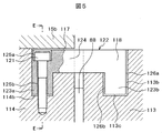
- FIG. 5 is an enlarged view of part C of FIG. 4 and shows a structure for fastening the first group inner barrel and the second group inner barrel.
- 6 is a cross-sectional view taken along line EE in FIG.
- a groove 117 having an L-shaped cross section extending in the circumferential direction in the vicinity of the end portion facing the discharge flow path 88 of the final stage compressor 80 and in the outer peripheral portion. Is formed.
- the inner barrel member 113 that forms the second group inner barrel is in the vicinity of the end facing the discharge flow path 88 of the final stage compressor 80 and has an L-shaped cross section extending in the circumferential direction at the outer peripheral portion.
- a groove 118 is formed.
- a plurality of connecting members 122 having a cross-sectional shape are fitted in these grooves 117 and 118 at intervals in the circumferential direction.
- the connecting member 122 having a cross-sectional shape has a bolt penetration part 123a on one side and a fitting part 123b on the other side, and a horizontal part 124 is connected therebetween.
- Bolt penetration part 123a fits into fitting part 114b which is a deep groove part of inner barrel member 114 of the 1st group inner barrel.
- the horizontal portion 124 spans between the two inner barrel members 114 and 113.
- the fitting part 123b is fitted into the fitting part 113c which is a deep groove part of the inner barrel member 113 of the second group inner barrel.
- the bolt penetration part 123a is formed with a bolt hole 125a in which the head of the bolt 121 is accommodated and a bolt hole 125b that is connected to the bolt hole and into which the threaded part of the bolt 121 is fitted.
- the bolt 121 is fitted into these holes 125 a and 125 b and screwed into the inner barrel member 114.
- the inner barrel member 113 and the connecting member 122 of the second group inner barrel are assembled while having gaps 113b and 126b exceeding the maximum manufacturing dimension error in the axial direction.
- the connecting member 122 and the inner barrel members 113 and 114 are fastened with bolts at a plurality of locations in the circumferential direction (three locations in FIG. 6). Thereby, the connecting member 122 is fixed to the first group inner barrel.
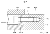
- FIG. 7 shows an enlarged view of a portion D in FIG.
- FIG. 7 shows a structure in which the second group inner barrel is connected to the drive-side head flange 11.
- a bolt groove 111c extending in the circumferential direction is formed in the vicinity of the inner barrel member 111 constituting the second group inner barrel near the side facing the suction flow path 18b of the third stage compressor 60.
- a plurality of through holes (bolt holes) 111d extending in the axial direction are formed on the side surface of the bolt groove 111c.
- the surface of the inner barrel member 111 on the suction channel 18b side is in contact with a spacer portion 146 that is ring-shaped and is cut out only in the suction channel 17b in the circumferential direction.
- the spacer portion 146 is formed with a plurality of bolt screw holes 146a extending in the axial direction. Therefore, the second group inner barrel and the drive-side head flange 11 are connected and integrated by screwing the bolt 131 into the bolt hole formed in the inner barrel member and the bolt screw hole 146a formed in the spacer portion 146. .
- impellers 41, 51,..., A collar 42, and the like are attached to the rotary shaft 30 to complete the rotor 3.
- the periphery of the rotor 3 is covered with an inner barrel 4 having a horizontally divided structure.
- the inner barrel 4 is grouped into the first group inner barrel and the second group inner barrel by the tie bolts 141 and 143. By connecting both groups with the connecting member 122, one inner barrel 4 is provided. Is formed.
- the inner barrel 4 and the driving side head flange 11 are fastened with bolts 131.
- the bolt 131 is fastened with a predetermined fastening force by using a tool such as a hexagon wrench from the outer peripheral side of the inner barrel 4.
- an assembly in which the driving side head flange 11, the inner barrel 4, and the rotor 3 are integrated is assembled into the outer barrel 2 from the non-driving side to the driving side (left side to right side in FIG. 1).
- the drive-side head flange 11 and the second group inner barrel are positioned on the outer barrel 2 using step portions 11d and 13d provided on the outer barrel 2 and the drive-side head flange 11, respectively.
- the inner barrel 4, more precisely, the first group inner barrel is positioned on the outer barrel 2 using the stepped portion 16 a provided in the outer barrel 2 and the stepped portion 16 b provided in the inner barrel member 116.
- the thrust side head flange 12 is assembled into the outer barrel 2.
- the shear keys 21 and 22 are attached to the groove portions 14 b formed on the inner surface side of the outer barrel 2. Thereby, the assembly of the main part of the multistage centrifugal compressor is completed.
- the connecting member 122 is fitted to the inner barrel member 113 with the axial gaps 113b and 126b that are equal to or larger than the axial maximum production dimension error of the inner barrel 4, so that the inner barrel 4 and the head flange Manufacturing errors and the like of each member such as 11 and 12 are absorbed by this fitting portion.
- the axial positioning of the multistage centrifugal compressor can be performed simply by pressing the stepped portion 11d of the driving side head flange and the stepped portion 16b of the inner barrel 4 against the two stepped portions 13d and 16a formed in the outer barrel 2. .
- there is no possibility that excessive stress caused by the dimensional error of the inner barrel is loaded on the positioning portions 11d and 13d and 16a and 16b.
- there is no need to adjust the axial length of the shear keys 21 and 22 by measuring the axial dimension of each component of the centrifugal compressor 200 during assembly.
- the operation of the centrifugal compressor 200 according to the present invention having the above configuration will be described.
- the working gas sucked from the suction flow path 17a is compressed by the first stage compressor 40 and the second stage compressor 50 to become high temperature and high pressure, and once from the discharge flow path 17c.
- a cooler (not shown)
- the positioning part and the load bearing part are shared by the step part of the inner barrel and the outer barrel and the shear key, so the discharge pressure during compressor operation is reliably ensured by the step part of the outer barrel and the head flange and the shear key. It is possible to bear the force that separates in the axial direction due to. As a result, the load can be borne up to a higher discharge pressure condition than in the case of the load borne by the fitting structure of the protrusion on the outer diameter side of the inner barrel and the inner groove of the outer barrel that has been conventionally used.
- SYMBOLS 1 Inner casing, 2 ... Outer barrel (outer casing), 3 ... Rotor, 4 ... Inner barrel, 10 ... (Barrel type) casing, 11 ... Drive side head flange, 11c ... Labyrinth seal, 11d ... Positioning part, 12 ... Thrust side head flange, 12a ... Stepped portion, 12c ... Labyrinth seal, 12f ... Hole, 13d ... Stepped portion, 14a ... Corner portion, 14b ... Groove portion, 16a, 16b ... Positioning portion, 17a, 17b ... Suction channel, 17c , 17d ... discharge flow path, 18a, 18b ... suction flow path, 21 ...
Landscapes
- Engineering & Computer Science (AREA)
- Mechanical Engineering (AREA)
- General Engineering & Computer Science (AREA)
- Structures Of Non-Positive Displacement Pumps (AREA)
Abstract
Description
特許文献1に記載の遠心圧縮機では、インナーバレル型ケーシングを有し、このケーシングの内周面であって軸方向端部近傍に円環状の溝を形成している。一方、ケーシングの軸方向端面を閉塞するヘッドカバーの外側外周部には、段付部が形成されている。そして、第1のシェアキーがケーシングの溝部およびヘッドカバーの段付部の双方に、この第1のシェアキーに隣接して配置された第2のシェアキーがケーシングの溝に、それぞれ係止している。
図1は、バレル型ケーシング10を有する一軸多段遠心圧縮機200の縦断面図である。図2は、図1のA矢視断面図でありロータ3部を除いた図、図3は図1のB矢視断面図でありロータ3部を除いた図である。また図4は、図1の要部の拡大詳細図である。
そして、インナーバレル部材111、112、113は、周方向に間隔をおいて複数本設けられたタイボルト143で連結されることにより、第2グループインナーバレルを構成する。第1グループインナーバレルを構成するインナーバレル部材114と第2グループインナーバレルを構成するインナーバレル部材113との間であって外径側には、最終段圧縮機80の吐出流路幅を確保するために、ベーン形状のスペーサ89が配置されている。
このロータ3の周囲を水平分割構造のインナーバレル4で覆う。上述した通り、インナーバレル4はタイボルト141、143により第1グループインナーバレルと第2グループインナーバレルにグループ化されているが、両グループを連結部材122で連結することにより、1個のインナーバレル4が形成される。次に、インナーバレル4と駆動側ヘッドフランジ11をボルト131で締結する。このボルト131は、インナーバレル4の外周側から六角レンチ等の工具を使用することで、所定の締結力で締結される。
その際、アウターバレル2及び駆動側ヘッドフランジ11のそれぞれに設けた段差部11d、13dを用いてアウターバレル2に駆動側ヘッドフランジ11及び第2グループインナーバレルを位置決めする。また、アウターバレル2に設けた段差部16a及びインナーバレル部材116に設けた段差部16bを用いて、インナーバレル4を、より正確には第1グループインナーバレルをアウターバレル2に位置決めする。
Claims (6)
- 回転軸に複数の羽根車が取り付けられてロータを形成する多段遠心流体機械であって、円筒形状のアウターケーシングと、このアウターケーシングに嵌合し前記ロータとの間で作動ガスの流路を形成するインナーケーシングを備え、前記インナーケーシングを前記アウターケーシングの一端側で固定するシェアキーを有し、前記インナーケーシングは駆動側ヘッドフランジとスラスト側ヘッドフランジと、前記駆動側ヘッドフランジとスラスト側ヘッドフランジの間に配置されるインナーバレルとを有し、前記インナーバレルを第1グループインナーバレルと第2グループインナーバレルとで構成し、これら第1グループインナーバレルと第2グループインナーバレルの各々は周方向複数個所に設けたタイボルトで締結されていると共に、各々の外周部に設けた溝部間を複数の連結部材で連結したことを特徴とする多段遠心流体機械。
- 前記連結部材は断面Π字型であって、前記第1、第2グループインナーバレルの一方のインナーバレルに形成された溝に固定され、他方のインナーバレルに形成された溝には軸方向に隙間を持って嵌合していることを特徴とする請求項1に記載の多段遠心流体機械。
- 前記隙間の大きさは、前記インナーケーシングの軸方向製作誤差以上であることを特徴とする請求項2に記載の多段遠心流体機械。
- 前記アウターバレルは少なくとも2段の段差を有し、一方の段差は前記駆動側ヘッドフランジに嵌合する部分に形成され、他方の段差はこの多段遠心圧縮機の初段の吸込み流路が形成されるインナーバレルの近傍に形成されていることを特徴とする請求項3に記載の多段遠心流体機械。
- 前記アウターバレルの2段の段差に対応して、前記駆動側ヘッドフランジ及び前記インナーバレルに前記アウターバレルの段差にインロー嵌めあい可能な段差を形成したことを特徴とする請求項4に記載の多段遠心流体機械。
- 前記タイボルトがこの圧縮機の吸込み流路を横切る部分に、ベーン形状のスペーサを前記タイボルトに対応して設け、このスペーサに前記タイボルトが貫通する孔を形成したことを特徴とする請求項1ないし5のいずれか1項に記載の多段遠心流体機械。
Priority Applications (3)
| Application Number | Priority Date | Filing Date | Title |
|---|---|---|---|
| CN201480021073.7A CN105121863A (zh) | 2013-04-15 | 2014-03-05 | 多级离心流体机械 |
| BR112015026187A BR112015026187A2 (pt) | 2013-04-15 | 2014-03-05 | máquina de fluido centrífuga com múltiplos estágios |
| RU2015144330A RU2015144330A (ru) | 2013-04-15 | 2014-03-05 | Многоступенчатая центробежная гидро(пневмо)машина |
Applications Claiming Priority (2)
| Application Number | Priority Date | Filing Date | Title |
|---|---|---|---|
| JP2013085110A JP6124659B2 (ja) | 2013-04-15 | 2013-04-15 | 多段遠心流体機械 |
| JP2013-085110 | 2013-04-15 |
Publications (1)
| Publication Number | Publication Date |
|---|---|
| WO2014171209A1 true WO2014171209A1 (ja) | 2014-10-23 |
Family
ID=51731168
Family Applications (1)
| Application Number | Title | Priority Date | Filing Date |
|---|---|---|---|
| PCT/JP2014/055546 WO2014171209A1 (ja) | 2013-04-15 | 2014-03-05 | 多段遠心流体機械 |
Country Status (5)
| Country | Link |
|---|---|
| JP (1) | JP6124659B2 (ja) |
| CN (1) | CN105121863A (ja) |
| BR (1) | BR112015026187A2 (ja) |
| RU (1) | RU2015144330A (ja) |
| WO (1) | WO2014171209A1 (ja) |
Cited By (1)
| Publication number | Priority date | Publication date | Assignee | Title |
|---|---|---|---|---|
| EP3346140A4 (en) * | 2015-11-27 | 2018-10-17 | Mitsubishi Heavy Industries Compressor Corporation | Fixing bolt for stationary member, and centrifugal compressor |
Families Citing this family (4)
| Publication number | Priority date | Publication date | Assignee | Title |
|---|---|---|---|---|
| IT201700007473A1 (it) * | 2017-01-24 | 2018-07-24 | Nuovo Pignone Tecnologie Srl | Treno di compressione con un compressore centrifugo e impianto lng |
| FR3063778A1 (fr) * | 2017-03-08 | 2018-09-14 | BD Kompressor GmbH | Turbocompresseur centrifuge |
| JP6908472B2 (ja) | 2017-08-31 | 2021-07-28 | 三菱重工コンプレッサ株式会社 | 遠心圧縮機 |
| JP6934781B2 (ja) * | 2017-09-06 | 2021-09-15 | 株式会社日立インダストリアルプロダクツ | 多段遠心流体機械 |
Citations (5)
| Publication number | Priority date | Publication date | Assignee | Title |
|---|---|---|---|---|
| GB956731A (en) * | 1961-08-11 | 1964-04-29 | Laval Steam Turbine Co | Improvements in or relating to multiple stage centrifugal pumps, compressors or the like |
| US3153383A (en) * | 1961-08-11 | 1964-10-20 | Laval Turbine | Means and method of assembling a pump, compressor, turbine or the like |
| JPS55137295U (ja) * | 1979-03-22 | 1980-09-30 | ||
| JPS6067797A (ja) * | 1983-09-22 | 1985-04-18 | ドレツサ−・インダストリ−ズ・インコ−ポレ−テツド | 多段遠心圧縮機 |
| JP2003269390A (ja) * | 2002-03-12 | 2003-09-25 | Mitsubishi Heavy Ind Ltd | 圧縮機 |
-
2013
- 2013-04-15 JP JP2013085110A patent/JP6124659B2/ja active Active
-
2014
- 2014-03-05 CN CN201480021073.7A patent/CN105121863A/zh active Pending
- 2014-03-05 WO PCT/JP2014/055546 patent/WO2014171209A1/ja active Application Filing
- 2014-03-05 RU RU2015144330A patent/RU2015144330A/ru unknown
- 2014-03-05 BR BR112015026187A patent/BR112015026187A2/pt not_active IP Right Cessation
Patent Citations (5)
| Publication number | Priority date | Publication date | Assignee | Title |
|---|---|---|---|---|
| GB956731A (en) * | 1961-08-11 | 1964-04-29 | Laval Steam Turbine Co | Improvements in or relating to multiple stage centrifugal pumps, compressors or the like |
| US3153383A (en) * | 1961-08-11 | 1964-10-20 | Laval Turbine | Means and method of assembling a pump, compressor, turbine or the like |
| JPS55137295U (ja) * | 1979-03-22 | 1980-09-30 | ||
| JPS6067797A (ja) * | 1983-09-22 | 1985-04-18 | ドレツサ−・インダストリ−ズ・インコ−ポレ−テツド | 多段遠心圧縮機 |
| JP2003269390A (ja) * | 2002-03-12 | 2003-09-25 | Mitsubishi Heavy Ind Ltd | 圧縮機 |
Cited By (2)
| Publication number | Priority date | Publication date | Assignee | Title |
|---|---|---|---|---|
| EP3346140A4 (en) * | 2015-11-27 | 2018-10-17 | Mitsubishi Heavy Industries Compressor Corporation | Fixing bolt for stationary member, and centrifugal compressor |
| US10801506B2 (en) | 2015-11-27 | 2020-10-13 | Mitsubishi Heavy Industries Compressor Corporation | Fixing bolt for stationary member, and centrifugal compressor |
Also Published As
| Publication number | Publication date |
|---|---|
| RU2015144330A (ru) | 2017-04-24 |
| CN105121863A (zh) | 2015-12-02 |
| JP2014206132A (ja) | 2014-10-30 |
| BR112015026187A2 (pt) | 2017-07-25 |
| JP6124659B2 (ja) | 2017-05-10 |
Similar Documents
| Publication | Publication Date | Title |
|---|---|---|
| EP2872744B1 (en) | A rotor for a radial compressor and a method for construction thereof | |
| WO2014171209A1 (ja) | 多段遠心流体機械 | |
| RU2551453C2 (ru) | Многоступенчатый ротор со стяжным стержнем и фланцем, закрепленным при помощи болтов, и способ сборки | |
| US8191374B2 (en) | Two-shaft gas turbine | |
| US10174628B2 (en) | Axially divided inner ring for a turbomachine and guide vane ring | |
| US9567864B2 (en) | Centrifugal impeller and turbomachine | |
| WO2013146590A1 (ja) | 静翼セグメント、及びこれを備えている軸流流体機械 | |
| JP3762661B2 (ja) | タービンロータ | |
| US11346364B2 (en) | Multistage centrifugal fluid machine | |
| JP2006138255A (ja) | タービンロータ及びガスタービン | |
| US9004857B2 (en) | Barrel-shaped centrifugal compressor | |
| JP2018168741A (ja) | フランジ同士が締結された流体装置の製造方法 | |
| JP2014206132A5 (ja) | ||
| WO2017086345A1 (ja) | 軸継手およびポンプ装置 | |
| JP4436273B2 (ja) | タービン仕切板及びそれを備えたタービン | |
| JP2011137454A (ja) | タービンエンジンロータブレード及びロータホイール | |
| US10539151B2 (en) | Centrifugal compressor casing and centrifugal compressor | |
| JP6655712B2 (ja) | 回転機械 | |
| JP4153446B2 (ja) | ガスタービン | |
| JP2006183465A (ja) | 遠心圧縮機 | |
| JP6128912B2 (ja) | 多段ポンプ | |
| US20220178331A1 (en) | Gas turbine for twin-rotor aircraft | |
| WO2017073499A1 (ja) | ターボ機械 | |
| JP2004150395A (ja) | 蒸気タービン仕切板および蒸気タービン |
Legal Events
| Date | Code | Title | Description |
|---|---|---|---|
| 121 | Ep: the epo has been informed by wipo that ep was designated in this application |
Ref document number: 14785171 Country of ref document: EP Kind code of ref document: A1 |
|
| ENP | Entry into the national phase |
Ref document number: 2015144330 Country of ref document: RU Kind code of ref document: A |
|
| NENP | Non-entry into the national phase |
Ref country code: DE |
|
| REG | Reference to national code |
Ref country code: BR Ref legal event code: B01A Ref document number: 112015026187 Country of ref document: BR |
|
| 122 | Ep: pct application non-entry in european phase |
Ref document number: 14785171 Country of ref document: EP Kind code of ref document: A1 |
|
| ENP | Entry into the national phase |
Ref document number: 112015026187 Country of ref document: BR Kind code of ref document: A2 Effective date: 20151015 |