WO2014168137A1 - Système optique de balayage et radar - Google Patents
Système optique de balayage et radar Download PDFInfo
- Publication number
- WO2014168137A1 WO2014168137A1 PCT/JP2014/060167 JP2014060167W WO2014168137A1 WO 2014168137 A1 WO2014168137 A1 WO 2014168137A1 JP 2014060167 W JP2014060167 W JP 2014060167W WO 2014168137 A1 WO2014168137 A1 WO 2014168137A1
- Authority
- WO
- WIPO (PCT)
- Prior art keywords
- mirror surface
- light
- angle
- mirror
- scanning
- Prior art date
Links
Images


Classifications
-
- G—PHYSICS
- G01—MEASURING; TESTING
- G01S—RADIO DIRECTION-FINDING; RADIO NAVIGATION; DETERMINING DISTANCE OR VELOCITY BY USE OF RADIO WAVES; LOCATING OR PRESENCE-DETECTING BY USE OF THE REFLECTION OR RERADIATION OF RADIO WAVES; ANALOGOUS ARRANGEMENTS USING OTHER WAVES
- G01S7/00—Details of systems according to groups G01S13/00, G01S15/00, G01S17/00
- G01S7/48—Details of systems according to groups G01S13/00, G01S15/00, G01S17/00 of systems according to group G01S17/00
- G01S7/481—Constructional features, e.g. arrangements of optical elements
- G01S7/4817—Constructional features, e.g. arrangements of optical elements relating to scanning
-
- G—PHYSICS
- G01—MEASURING; TESTING
- G01S—RADIO DIRECTION-FINDING; RADIO NAVIGATION; DETERMINING DISTANCE OR VELOCITY BY USE OF RADIO WAVES; LOCATING OR PRESENCE-DETECTING BY USE OF THE REFLECTION OR RERADIATION OF RADIO WAVES; ANALOGOUS ARRANGEMENTS USING OTHER WAVES
- G01S17/00—Systems using the reflection or reradiation of electromagnetic waves other than radio waves, e.g. lidar systems
- G01S17/02—Systems using the reflection of electromagnetic waves other than radio waves
- G01S17/06—Systems determining position data of a target
- G01S17/42—Simultaneous measurement of distance and other co-ordinates
-
- G—PHYSICS
- G01—MEASURING; TESTING
- G01S—RADIO DIRECTION-FINDING; RADIO NAVIGATION; DETERMINING DISTANCE OR VELOCITY BY USE OF RADIO WAVES; LOCATING OR PRESENCE-DETECTING BY USE OF THE REFLECTION OR RERADIATION OF RADIO WAVES; ANALOGOUS ARRANGEMENTS USING OTHER WAVES
- G01S17/00—Systems using the reflection or reradiation of electromagnetic waves other than radio waves, e.g. lidar systems
- G01S17/88—Lidar systems specially adapted for specific applications
- G01S17/93—Lidar systems specially adapted for specific applications for anti-collision purposes
- G01S17/931—Lidar systems specially adapted for specific applications for anti-collision purposes of land vehicles
-
- G—PHYSICS
- G02—OPTICS
- G02B—OPTICAL ELEMENTS, SYSTEMS OR APPARATUS
- G02B26/00—Optical devices or arrangements for the control of light using movable or deformable optical elements
- G02B26/08—Optical devices or arrangements for the control of light using movable or deformable optical elements for controlling the direction of light
- G02B26/10—Scanning systems
- G02B26/12—Scanning systems using multifaceted mirrors
- G02B26/129—Systems in which the scanning light beam is repeatedly reflected from the polygonal mirror
Definitions
- the present invention relates to a scanning optical system and a radar suitable for use in a radar that detects an object by irradiating a laser beam or the like.
- a laser radar which is a distance measuring device using optical scanning is known.
- a general laser radar is a device that measures the distance from the time it takes to project a laser beam and detect reflected light to the obstacle.
- the detection range can be expanded by narrowing the luminous flux for scanning.
- a technique of rotating or swinging a mirror or a polygon mirror having a plurality of mirror surfaces is known.
- the projection range in the scanning angle direction is determined by the scanning angle and the spot size, but since the scanning angle direction of the laser light is the mirror rotation direction, there is no need to make the spot size larger in the scanning angle direction, and the resolution is reduced. In order to increase, a shorter spot size in the scanning angle direction is preferred.
- the light projection range in the sub-scanning angle direction orthogonal to the scanning angle direction is determined by the number of scanning lines and the light projection spot size (or the field of view of the light receiving lens). Since there is a limit to increasing the number of scanning lines, the projection spot size is increased in the sub-scanning angle direction at the center of the scanning angle, and thus the spot size is often different between the horizontal direction and the vertical direction.
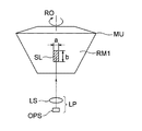
- FIG. 1 schematically showing a laser radar, a mirror unit MU having a reflecting surface RM1 inclined with respect to the rotation axis RO is rotated about the rotation axis RO.
- the spot light SL emitted from the light source LD of the light projecting system LP in the direction along the rotation axis RO has different aspect ratios. Accordingly, in FIG.
- the spot light SL (cross section is hatched) in the measurement range reflected by the reflective surface RM1 travels in the direction perpendicular to the paper surface, but the cross section is long in the scanning angle direction (left and right direction in the figure).
- the rectangular cross section has a length of a and a length in the sub-scanning angle direction (vertical direction in the figure) of b (> a).
- This shift amount is represented by an angle shift ( ⁇ ) in the sub-scanning angle direction.
- ⁇ angle shift
- the spot light rotates, thereby narrowing the spot light interval or opening the interval.
- the rotation angle ⁇ is called a spot rotation angle.
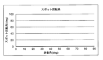
- FIG. 3 is a diagram showing the relationship between the scanning angle and the spot rotation angle when a light beam is incident parallel to the rotation axis on a reflection surface inclined by 45 ° with respect to the rotation axis.
- the scanning angle is the same as the rotation angle.
- the spot rotation angle ⁇ increases as the rotation angle ⁇ of the reflecting surface RM1 increases.
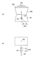
- Patent Document 1 discloses a technique for correcting the longitudinal distortion shown in FIG. 4A in a wide scanning range as shown in FIG. 4B by tilting the rotation axis of the reflecting surface. The rotation of light is not taken into consideration. Moreover, there exists a problem that arrangement
- the present invention has been made in view of the above circumstances, and includes a scanning optical system and a radar capable of suppressing longitudinal distortion and spot rotation of spot light irradiated on an object and suppressing a change in resolution while having a wide visual field range.
- the purpose is to provide.
- the scanning optical system includes: A rotating mirror unit having a first mirror surface and a second mirror surface inclined with respect to the rotation axis; A light projecting system including at least one light source that emits a light beam toward an object through the mirror unit; The light beam emitted from the light source is reflected by the first mirror surface of the mirror unit, then travels toward the second mirror surface, is further reflected by the second mirror surface, and rotates the mirror unit.
- the object is projected while being scanned,
- the light beam emitted from the light projecting system is longer in the sub-scanning angle direction than the scanning angle direction in the measurement range of the object, and satisfies the following conditional expression.
- a first mirror surface and a second mirror surface are formed on a rotating mirror unit at an angle of 90 °, and a light beam emitted from a light source along a direction orthogonal to the rotation axis is used.
- a configuration is disclosed in which scanning is performed by reflecting twice on the first mirror surface and the second mirror surface, so that the scanning line is not disturbed even if the rotation axis is tilted due to rotational shaking.
- a general scanning radar scans the measurement range using a vertically long spot light, and thus has the following problems.
- the direction orthogonal to the rotation axis is the scanning angle direction
- the method parallel to the rotation axis is the sub-scanning angle direction.
- the center of the scanning angle is obtained by reversing the angle in the scanning angle direction of the optical axis of the light projecting system immediately before hitting the first mirror surface by 180 degrees.
- the angle in the sub-scanning angle direction is the sub-scanning angle with respect to the scanning angle direction
- the center of the sub-scanning angle is an angle orthogonal to the rotation axis.
- “Vertical distortion” refers to an angular deviation in the sub-scanning angle direction when the periphery is scanned with respect to the angle in the sub-scanning angle direction at the center of the scanning angle.
- the “spot rotation angle” refers to an angle that rotates around the light projection direction with reference to the spot at the center of the scanning angle.
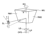
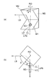
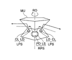
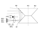
- the optical axis SO of the light projecting system LPS having the light source LD and the collimating lens CL with respect to the rotation axis RO of the mirror unit MU having the first mirror surface M1 and the second mirror surface M2. are arranged so as to be orthogonal to each other.
- the projection system LPS is arranged on the first mirror surface M1 side with reference to the vertex of the intersection angle formed by the first mirror surface M1 and the second mirror surface M2.
- the first mirror surface M1 is tilted by ⁇ 45 degrees with respect to the optical axis direction of the light projecting system LPS from the plane orthogonal to the rotation axis RO, and the light projection system LPS from the plane orthogonal to the rotation axis. Inclined by +45 degrees in the optical axis direction.
- the rotational position of the mirror unit MU becomes an angle at which the optical axis SO of the light projecting system LPS is located in a plane including the normal lines of the first mirror surface M1 and the second mirror surface M2.
- the light beam LB emitted from the light projecting system LPS is reflected by the first mirror surface M1, travels parallel to the rotation axis RO, and then travels on the second mirror surface M2. Reflected.
- the reflected light beam LB is projected from the second mirror M2 onto the object.
- the optical axis SO of the light projecting system LPS may be shifted from the rotation axis RO to the left and right.
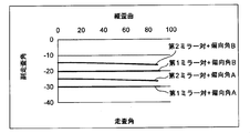
- FIG. 8 shows the relationship between the longitudinal distortion (indicated by the sub-scanning angle) and the scanning angle ⁇ in this case
- FIG. 9 shows the relationship between the spot rotation angle and the scanning angle ⁇ .
- the measurement range may not be a sub-scanning angle of 0 °, or the incident angle and the sub-scanning angle may not match.
- the mirror unit is provided with a plurality of pairs of the first mirror surface and the second mirror surface, and each light beam passing through each mirror pair is shifted in the sub-scanning angle direction and can be scanned at different sub-scanning angle direction positions.
- it is necessary to shift the angle formed by the first mirror surface and the second mirror surface from 90 °.
- the angle formed by the first mirror surface and the second mirror surface is shifted from 90 °, there is a problem that longitudinal distortion and spot rotation increase.
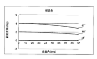
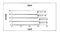
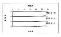
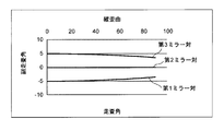
- FIG. 10 shows the relationship between the scanning angle and the longitudinal distortion when the tilt angle of the first mirror surface M1 is changed.
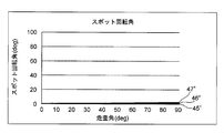
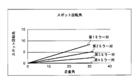
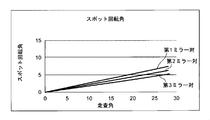
- FIG. 11 shows the relationship between the scanning angle and the spot rotation when the tilt angle of the first mirror surface M1 is changed.
- the rotation angle is as shown in FIGS.
- the angle between the first mirror surface and the second mirror surface changes, the degree of change in longitudinal distortion and spot rotation changes, so the angle of the first mirror surface and the individual angle of the second mirror surface can be set freely. You can see that Further, it is not necessary to rotate at a constant speed as in the case of a laser printer, and when it is desired to project light only in a specific direction, it can be stopped by rotating it by a necessary angle or can be swung back and forth.
- the spot rotation be within 15 °, preferably within 10 ° from the center of the scanning angle, considering that the light projection spots overlap and the interval is increased. all right. It has been found that the longitudinal distortion is desired to be within 1/8, preferably within 1/10 of the scanning angle.
- Conditional expression (1) is a conditional expression that suppresses spot rotation and longitudinal distortion in the range of scanning angle ⁇ 90 degrees and sub-scanning angle ⁇ 30 degrees. If it is within the range of conditional expression (1), the spot rotation and the longitudinal distortion can be suppressed to a range with no problem, but should not be interpreted as being limited to this range.
- the following formula is satisfied.
- the radar according to the present invention has the above-described scanning optical system.
- ⁇ Distance measurement with TOF can be performed by using pulsed LED or laser as light source of radar. Compared with the scanning optical system used in conventional radars that use TOF, there is little change in resolution over a wide scanning angle, so it is possible to provide a radar with a wide viewing angle that can be used effectively.
- a scanning optical system and a radar that can suppress longitudinal distortion and spot rotation of spot light irradiated on an object, and can suppress a change in resolution while having a wide visual field range.
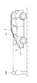
- (A) is a front view of the radar concerning an example of this invention
- (b) is the figure seen in the rotating shaft direction
- 6 is a graph showing the relationship between the scanning angle and the longitudinal distortion in the radar according to the first embodiment.
- 3 is a graph showing a relationship between a scanning angle and a spot rotation angle (absolute value) in the radar according to the first embodiment. It is a graph which shows the relationship between the scanning angle in the radar of Example 2, and longitudinal distortion. It is a graph which shows the relationship between the scanning angle and spot rotation angle (absolute value) in the radar of Example 2.
- FIG. 16 is a schematic view showing a state in which the laser radar according to the present embodiment is mounted on a vehicle.
- the laser radar LR of the present embodiment is provided behind the front window 1a of the vehicle 1 or behind the front grille 1b.
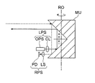
- FIG. 17 is a schematic configuration diagram of the laser radar LR according to the present embodiment, and is a diagram seen from the horizontal direction. However, the shape and length of the components may differ from the actual ones.
- the laser radar LR for example, a pulsed semiconductor laser LD that emits a laser beam, a collimating lens CL that converts divergent light from the semiconductor laser LD into parallel light, and laser light that is collimated by the collimating lens CL, A mirror unit MU that scans and projects light toward the object OBJ side (FIG.
- the semiconductor laser LD and the collimating lens CL constitute a light projecting system LPS
- the lens LS and the photodiode PD constitute a light receiving system RPS.
- the light beam emitted from the light projecting system LPS is longer in the sub-scanning angle direction than in the scanning angle direction in the measurement range of the object (see FIG. 1A).
- the substantially square cylindrical mirror unit MU is rotatably held around a rotation axis RO that is an axis, and four trapezoidal first mirror surfaces M1 are arranged on the outer periphery of the lower portion, and face each other.
- four trapezoidal second mirror surfaces M2 are arranged on the outer periphery of the upper portion.
- the crossing angles of the first mirror surface M1 and the second mirror surface M2 that are paired vertically are different.
- the following conditional expression is satisfied.
- optical axes of the light projecting system LPS and the light receiving system RPS are orthogonal to the rotational axis RO of the mirror unit MU, and the light projecting system LPS is arranged farther in the direction of the rotational axis RO than the light receiving system RPS.
- the divergent light intermittently emitted from the semiconductor laser LD in pulses is converted into a parallel light beam by the collimator lens CL, enters the point P1 of the first mirror surface M1 of the rotating mirror unit MU, and is reflected here.
- the light travels toward the second mirror surface M2, is further reflected at the point P2 on the second mirror surface M2, and is scanned and projected toward the object OBJ.
- FIG. 18 is a diagram showing a state in which the screen G, which is the detection range of the laser radar LR, is scanned with the emitted laser spot light SB (shown by hatching) according to the rotation of the mirror unit MU.
- the crossing angles are different.
- the laser light is sequentially reflected by the first mirror surface M1 and the second mirror surface M2 that rotate, but first the laser light reflected by the first pair of the first mirror surface M1 and the second mirror surface M2. Is scanned in the horizontal direction from left to right in the uppermost region Ln1 of the screen G in accordance with the rotation of the mirror unit MU.
- the laser light reflected by the second pair of the first mirror surface M1 and the second mirror surface M2 passes from the left in the horizontal direction to the second region Ln2 from the top of the screen G according to the rotation of the mirror unit MU. Scan to the right.
- the laser light reflected by the third pair of the first mirror surface M1 and the second mirror surface M2 moves from the left in the horizontal direction to the third region Ln3 from the top of the screen G according to the rotation of the mirror unit MU.
- the laser light reflected by the fourth pair of the first mirror surface M1 and the second mirror surface passes through the lowermost region Ln4 of the screen G from the left to the right in the horizontal direction according to the rotation of the mirror unit MU. Scanned.
- the scanning of one screen is completed.
- the mirror unit MU makes one rotation, if the first pair of the first mirror surface M1 and the second mirror surface M2 return, the scanning from the top of the screen G is repeated again.
- the crossing angle in each pair is other than 90 degrees and is different from each other, the emission timing of the laser light when projecting to the pair whose crossing angle is apart from 90 degrees is set so that the crossing angle is more than that. It is preferable that it is later than the emission timing of the laser light when projecting to a pair close to 90 degrees.
- the laser beam reflected and reflected by the object OBJ out of the projected light beam is incident again on the point P3 of the second mirror surface M2 of the mirror unit MU, reflected here, and along the rotation axis RO.
- the light travels further, is reflected at the point P4 on the first mirror surface M1, is condensed by the lens LS, and is detected by the light receiving surface of the photodiode PD.
- the object OBJ can be detected in the entire range on the screen G.
- FIG. 19 is a diagram illustrating a configuration of a radar according to a modification according to the present embodiment.
- the mirror unit MU having a substantially pentagonal cylindrical shape has five trapezoidal first mirror surfaces M1 arranged on the outer periphery of the lower portion, and five pieces on the upper outer periphery facing it.
- the trapezoidal second mirror surface M2 is arranged.
- two light projecting systems LPS are provided in parallel in the horizontal direction.
- the reflected light of the two-way laser light projected by the two light projecting systems LPS can be received particularly at a position where the light receiving system RPS faces the ridge line of the mirror unit MU, so that the scanning range can be increased. Widely secured.
- Other configurations are the same as those in the above-described embodiment.
- FIG. 28 is a diagram showing a configuration of a radar according to another modification according to the present embodiment.
- the light receiving system RPS is configured by a lens LS and a light receiving sensor RS.
- the light receiving sensor RS is composed of a plurality of light receiving elements RS1 to RS3 arranged in parallel with the rotation axis RO and arranged in the vertical direction in the figure. Since the light receiving sensor RS has the light receiving elements RS1 to RS3 for three pixels in this way, the light receiving field is increased, and the chief ray indicated by the solid line in the figure enters the center light receiving element RS1, and is indicated by the broken line.
- the field of view can be divided in the vertical direction (vertical direction) in the figure, and the resolution is improved.
- Other configurations are the same as those in the above-described embodiment.
- the first embodiment is a radar using a resin-made mirror unit having four pairs of first mirror surfaces and second mirror surfaces (hereinafter referred to as mirror pairs). Therefore, the number of scanning lines is four.
- Table 1 shows the specifications of the radar of Example 1. Referring to FIG.
- FIG. 20 is a graph showing the relationship between the scanning angle and the longitudinal distortion in the radar according to the first embodiment
- FIG. 21 is a graph showing the relationship between the scanning angle and the spot rotation angle (absolute value) in the radar according to the first embodiment. It is.
- Example 1 assuming that the intersection angle between the first mirror surface and the second mirror surface is ⁇ 1 and the rotation angle is ⁇ ,
- 225 as the maximum value.
- the incident angle ⁇ is 0 °. From Example 1, it can be seen that the larger the crossing angle, the smaller the scanning angle even at the same rotation angle.
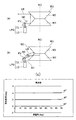
- Example 2 is a radar using a resin mirror unit having two mirror pairs, one light projecting system, and one polarizer.
- the deflector is a mirror, and the incident angle of the light beam emitted from the deflection angle A is ⁇ 30 °, and the incident angle of the light beam emitted from the other deflection angle B is ⁇ 20 °. With these combinations, the number of scanning lines is four.
- Table 2 shows the specifications of the radar of Example 2.
- FIG. 22 is a graph showing the relationship between the scanning angle and the longitudinal distortion in the radar according to the second embodiment
- FIG. 23 is a graph showing the relationship between the scanning angle and the spot rotation angle (absolute value) in the radar according to the second embodiment. It is.
- Example 2 if the intersection angle between the first mirror surface and the second mirror surface is ⁇ 1 and the rotation angle is ⁇ , the maximum value of
- Two incident angles were obtained by the deflector, but using two projection systems, the incident angle of the light beam of the light projecting system A is ⁇ 30 °, and the incident angle of the light beam emitted from the other light projecting system B is ⁇ 20 °. May be used.
- Example 3 is a radar using a resin mirror unit having three mirror pairs. Therefore, the number of scanning lines is three. Table 3 shows the specifications of the radar of Example 3.
- FIG. 24 is a graph showing the relationship between the scanning angle and the longitudinal distortion in the radar according to the third embodiment
- FIG. 25 is a graph showing the relationship between the scanning angle and the spot rotation angle (absolute value) in the radar according to the third embodiment. It is.
- Example 3 assuming that the intersection angle between the first mirror surface and the second mirror surface is ⁇ 1 and the rotation angle is ⁇ , the maximum value of
- the incident angle ⁇ is 30 °.
- Example 4 is a radar using a resin mirror unit having three mirror pairs. Therefore, the number of scanning lines is three. Table 4 shows the specifications of the radar of Example 4.
- FIG. 26 is a graph showing the relationship between the scanning angle and the longitudinal distortion in the radar of Example 4, and
- FIG. 27 is a graph showing the relationship between the scanning angle and the spot rotation angle (absolute value) in the radar of Example 4. It is. In Example 4, assuming that the intersection angle between the first mirror surface and the second mirror surface is ⁇ 1 and the rotation angle is ⁇ ,
- 112.5. The incident angle ⁇ is 0 °.
- the mirror unit preferably includes a plurality of pairs of the first mirror surface and the second mirror surface, and the crossing angles in each pair are different. As described above, by making the crossing angles of the plurality of pairs of the first mirror surface and the second mirror surface different, the spot light reflected from the first pair of the first mirror surface and the second mirror surface, The projection position in the sub-scanning angle direction of the spot light reflected from the second pair of the first mirror surface and the second mirror surface can be changed, whereby the length of the spot light in the sub-scanning angle direction can be changed. Even if is reduced, a wide measurement range can be two-dimensionally scanned.
- the scanning angle can be made larger than the rotation angle, and the pair of the first mirror surfaces. Since the rotation angle required for scanning on the second mirror surface can be made smaller than that shown in FIG. 1, for example, the number of scanning lines in the sub-scanning angle direction can be increased.
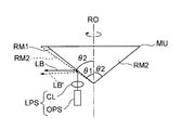
- mirror unit MU of the scanning optical system shown in FIG. 12 as a comparative example, mirror surfaces RM1 and RM2 extending perpendicularly to the paper surface are combined with their back surfaces facing each other.
- the inclination angle ⁇ 1 of the mirror surface RM1 with respect to the rotation axis RO is different from the inclination angle ⁇ 2 of the mirror surface RM2 with respect to the rotation axis RO.
- the number of scanning lines that can be changed only by the inclination angles ⁇ 1 and ⁇ 2 of the mirror surfaces RM1 and RM2 of the mirror unit MU is 2 at maximum.
- the number of scanning lines can be made four by using four pairs of the first mirror surface and the second mirror surface, each having a different crossing angle. It is. It is also possible to increase the scanning angle by reducing the number of scanning lines.
- a deflecting element for changing a traveling direction of a light beam emitted from the light projecting system is provided between the light source and the mirror unit.
- the vertical distortion is increased by shifting the crossing angle between the first mirror surface and the second mirror surface from 90 °, but the incident angle ⁇ to the first mirror surface is set in the sub-scanning angle direction. It is possible to perform scanning without greatly shifting the crossing angle from 90 degrees.
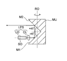
- a reflecting mirror BE is used as an example of a polarizing element, and a light beam LB from the light projecting system LPS is reflected, reflected by the first mirror surface M1, and then reflected by the second mirror surface M2.
- FIG. 13C is a diagram showing the relationship between the scanning angle and the longitudinal distortion when the incident angle to the first mirror surface M1 is changed using the reflecting mirror BE in the state where the crossing angle is 90 °. is there. Thus, if the crossing angle is 90 °, the longitudinal distortion does not change.
- the reflecting mirror since scanning cannot be performed while the reflecting mirror is rotated, for example, when there are three or more pairs of the first mirror surface and the second mirror surface, after scanning with the first to third mirror surfaces, The reflecting mirror may be rotated while the first pair of mirror surfaces pass, and the second, third, and first pair of mirror surfaces after rotation may be scanned in different sub-scanning ranges and the order may be changed. .
- the spot light can be moved in the sub-scanning angle direction by changing the incident angle to the first mirror surface, but as described above, the first mirror surface and the second mirror surface If the crossing angle deviates from 90 °, spot rotation occurs as it goes around the scanning angle (see FIG. 11). Therefore, since the spot light is moved on the extended line where the spot rotation has occurred, by using the intersection angle between the first mirror surface and the second mirror surface that can suppress the spot rotation, the periphery of the scanning angle is obtained. However, it is possible to perform scanning while suppressing changes in the measurement range.
- the deflection angle is used to correct the incident angle. May be adjusted to a desired value.
- the mirror unit has a plurality of pairs of the first mirror surface and the second mirror surface, the crossing angles in each pair are different, and the light projecting system between the light source and the mirror unit. It is preferable that a deflection element for changing a traveling direction of the light beam emitted from the first mirror surface and a sub-scanning angle of an intersection angle between the first mirror surface and the second mirror surface are continuous.
- the incident angle to the first mirror surface is changed by using the deflection element.
- the scanning lines can be arbitrarily increased. In FIG. 13, this corresponds to the case where the mirror unit MU has a plurality of pairs of first mirror surfaces M1 and second mirror surfaces M2 with different crossing angles. In the case where there are a plurality of crossing angles between the first mirror surface and the second mirror surface, if the crossing angles are separated from each other, the crossing angle is 90 ° at which no theoretical vertical distortion occurs. Distortion will occur.
- the intersecting angle between the first mirror surface and the second mirror surface is 90 ° by scanning at an adjacent scanning angle.
- the sub-scanning angle can be increased by the deflection element. “Continuous” means that the deflection angle (angular difference) by the deflecting element is larger than the deflection angle (angular difference) in the sub-scanning angle direction due to the intersection angle between the first mirror surface and the second mirror surface. . It is not always necessary to scan in order of rotation.
- the mirror unit is preferably made of resin. Since the mirror unit according to the present invention combines the first mirror surface and the second mirror surface, the mirror unit tends to increase in size in the rotation axis direction. For this reason, the weight is often larger than that of a mirror or a polygon mirror as known in known examples. Further, if the center of gravity is located at a position farther away from a power source such as a motor, shaft shake is likely to occur. When the axis shake occurs, there is a deviation between the scanning evaluation angle and the sub-scanning angle.For example, when the rotation axis is tilted forward and backward with the object on the front, the vertical direction is increased toward the periphery of the scanning angle. Distortion will come out.
- the mirror unit is made of resin to reduce the weight, it is possible to obtain a mirror unit in which axial blurring hardly occurs.
- the first mirror surface and the second mirror surface can be formed by attaching a reflection film, a metal polishing mirror, or a fill mirror to the mirror unit by reflecting, coating, or plating the reflection layer on the mirror unit.
- the mirror unit is made of resin such as polycarbonate or acrylic when used in an environment with temperature changes, the projected light flux may be destroyed due to changes such as high coefficient of thermal expansion and distortion of the surface due to temperature changes. There is. Therefore, when used in an environment with a temperature change, the mirror unit may be manufactured using a metal such as aluminum having a low coefficient of thermal expansion.
- conditional expression (2) As the crossing angle between the first mirror surface and the second mirror surface is more than 90 degrees, vertical distortion and spot rotation are more likely to occur when scanning around the scanning angle. If it is within the range of conditional expression (2), the incident angle and the sub-scanning angle are close to each other, so that the crossing angle between the first mirror surface and the second mirror surface does not have to be separated from 90 degrees, and the vertical distortion And the spot rotation can be suppressed. Further, when the incident angle is close to an angle orthogonal to the rotation axis, longitudinal distortion and spot rotation can be suppressed if the intersection angle between the first mirror surface and the second mirror surface is the same. Desirably, the following conditional expression is satisfied.
- the light projecting systems are provided, and the light beams emitted from the light projecting systems have different angles with respect to a plane orthogonal to the rotation axis when entering the first mirror surface.
- the sub-scanning range can be increased while using the vicinity of an intersection angle of 90 ° between the first mirror surface and the second mirror surface.
- a light receiving system that receives reflected light of a light beam scanned through the mirror unit and projected onto the object.
- a light receiving system that receives reflected light of a light beam scanned through the mirror unit and projected onto the object.
- the reflected light from the object is preferably reflected by the second mirror surface, then reflected by the first mirror surface, and received by the light receiving system.
- the light receiving system is used as a two-dimensional sensor (CMOS, It is difficult to receive light with a CCD or the like) and a lens, and it is difficult to obtain a necessary object-side aperture diameter. Even if light can be received, the resolution changes due to lens distortion. Therefore, as shown in FIG.
- the light projecting system LPS is arranged closer to the second mirror surface in the direction of the rotation axis RO than the light receiving system RPS, so that the optical axes are orthogonal to the rotation axis and the optical axes are parallel to each other. Then, the reflected light from the object is reflected on the second mirror surface M2, then reflected on the first mirror surface M1, and received by the image sensor PD through the lens LS of the light receiving system RPS, for example, full-width
- the same resolution as the light projecting system LPS can be obtained in the range of 180 degrees.
- the optical axes of the light receiving system RPS and the light projecting system LPS are preferably parallel to each other, but they may be received by shifting the optical axes by a lens or a free-form surface mirror.
- a bilaterally symmetric scanning angle can be obtained. However, if there is a margin for the scanning angle, it may be shifted to the left and right.
- the light receiving system includes a light receiving sensor including a plurality of light receiving elements so as to divide the visual field at least in the long side direction of the emitted light beam of the light projecting system. Since the light beam emitted from the light projecting system is made longer in each sub-scan direction than the scan angle direction within the measurement range of the object, the rotation of the spot can be reduced. Although enlargement can be performed, the resolution is reduced accordingly. Therefore, by arranging multiple light receiving elements at least in the same direction as the long side of the light beam emitted from the light projecting system, the field of view can be widened and the field of view can be divided to improve resolution. it can. For example, as shown in FIG. 28, the visual field can be divided by arranging a plurality of light receiving elements in the rotation axis direction.
- the crossing angle in at least one pair is other than 90 degrees, and light is projected to a pair whose crossing angle is away from 90 degrees. It is preferable that the light emission timing of the light source is set later than the light emission timing of the light source when light is projected to a pair whose intersection angle is close to 90 degrees (including the case where the crossing angle is 90 degrees). When the crossing angle is more than 90 degrees, the rotation angle and the scanning angle are close to each other. For this reason, if the light emission timing is the same at different crossing angles, there is a risk that the spotlights will be clogged or separated. Therefore, it is possible to reduce the change in resolution by delaying the light emission timing of the light source as the crossing angle is away from 90 degrees.
Landscapes
- Physics & Mathematics (AREA)
- Engineering & Computer Science (AREA)
- General Physics & Mathematics (AREA)
- Computer Networks & Wireless Communication (AREA)
- Radar, Positioning & Navigation (AREA)
- Remote Sensing (AREA)
- Electromagnetism (AREA)
- Optics & Photonics (AREA)
- Optical Radar Systems And Details Thereof (AREA)
- Mechanical Optical Scanning Systems (AREA)
- Measurement Of Optical Distance (AREA)
Abstract
Priority Applications (4)
| Application Number | Priority Date | Filing Date | Title |
|---|---|---|---|
| US14/782,505 US10078132B2 (en) | 2013-04-11 | 2014-04-08 | Scanning optical system and radar |
| EP14782429.6A EP2985650B1 (fr) | 2013-04-11 | 2014-04-08 | Système optique de balayage et radar |
| JP2015511262A JP5754564B2 (ja) | 2013-04-11 | 2014-04-08 | 走査光学系及びレーダー |
| US16/106,924 US10989794B2 (en) | 2013-04-11 | 2018-08-21 | Scanning optical system and radar |
Applications Claiming Priority (2)
| Application Number | Priority Date | Filing Date | Title |
|---|---|---|---|
| JP2013082609 | 2013-04-11 | ||
| JP2013-082609 | 2013-04-11 |
Related Child Applications (2)
| Application Number | Title | Priority Date | Filing Date |
|---|---|---|---|
| US14/782,505 A-371-Of-International US10078132B2 (en) | 2013-04-11 | 2014-04-08 | Scanning optical system and radar |
| US16/106,924 Continuation US10989794B2 (en) | 2013-04-11 | 2018-08-21 | Scanning optical system and radar |
Publications (1)
| Publication Number | Publication Date |
|---|---|
| WO2014168137A1 true WO2014168137A1 (fr) | 2014-10-16 |
Family
ID=51689544
Family Applications (1)
| Application Number | Title | Priority Date | Filing Date |
|---|---|---|---|
| PCT/JP2014/060167 WO2014168137A1 (fr) | 2013-04-11 | 2014-04-08 | Système optique de balayage et radar |
Country Status (4)
| Country | Link |
|---|---|
| US (2) | US10078132B2 (fr) |
| EP (1) | EP2985650B1 (fr) |
| JP (2) | JP5754564B2 (fr) |
| WO (1) | WO2014168137A1 (fr) |
Cited By (19)
| Publication number | Priority date | Publication date | Assignee | Title |
|---|---|---|---|---|
| WO2016056545A1 (fr) * | 2014-10-09 | 2016-04-14 | コニカミノルタ株式会社 | Système optique de balayage, et dispositif de projection et de réception de lumière |
| WO2016056544A1 (fr) * | 2014-10-09 | 2016-04-14 | コニカミノルタ株式会社 | Système optique de balayage, et dispositif de projection et de réception de lumière |
| WO2016059948A1 (fr) * | 2014-10-15 | 2016-04-21 | コニカミノルタ株式会社 | Dispositif optique de balayage |
| WO2017010176A1 (fr) * | 2015-07-14 | 2017-01-19 | コニカミノルタ株式会社 | Dispositif de radar laser |
| WO2017010197A1 (fr) * | 2015-07-14 | 2017-01-19 | コニカミノルタ株式会社 | Dispositif de moulage, produit moulé, unité miroir et procédé de moulage |
| WO2017018064A1 (fr) * | 2015-07-24 | 2017-02-02 | コニカミノルタ株式会社 | Dispositif de moulage, objet moulé et unité de miroir |
| WO2017018065A1 (fr) * | 2015-07-27 | 2017-02-02 | コニカミノルタ株式会社 | Unité miroir et dispositif de détection d'objet de type à balayage optique |
| JP2017026523A (ja) * | 2015-07-24 | 2017-02-02 | コニカミノルタ株式会社 | レーザレーダ装置及びその制御方法 |
| WO2017065049A1 (fr) * | 2015-10-16 | 2017-04-20 | コニカミノルタ株式会社 | Dispositif de détection d'objet de type à balayage optique |
| WO2017065048A1 (fr) * | 2015-10-16 | 2017-04-20 | コニカミノルタ株式会社 | Dispositif de détection d'objet de type à balayage optique |
| EP3203259A1 (fr) * | 2016-02-03 | 2017-08-09 | Konica Minolta, Inc. | Dispositif de détection d'objet de type à balayage optique |
| WO2017135225A1 (fr) * | 2016-02-03 | 2017-08-10 | コニカミノルタ株式会社 | Dispositif de détection d'objet de type à balayage optique |
| WO2018143093A1 (fr) * | 2017-01-31 | 2018-08-09 | パイオニア株式会社 | Dispositif de mesure |
| WO2018147454A1 (fr) * | 2017-02-09 | 2018-08-16 | コニカミノルタ株式会社 | Système optique de balayage et dispositif radar laser |
| WO2018147453A1 (fr) * | 2017-02-09 | 2018-08-16 | コニカミノルタ株式会社 | Système optique de balayage et dispositif de radar laser |
| EP3413078A4 (fr) * | 2016-02-03 | 2019-03-13 | Konica Minolta, Inc. | Dispositif de détection d'objets du type à balayage optique |
| CN112997099A (zh) * | 2018-11-13 | 2021-06-18 | 纽诺有限公司 | 用于车辆盲点检测的光检测与测距 |
| JP2022518493A (ja) * | 2019-01-23 | 2022-03-15 | ロベルト・ボッシュ・ゲゼルシャフト・ミト・ベシュレンクテル・ハフツング | 光学系、特にLiDARシステム、および車両 |
| US11726182B2 (en) * | 2018-10-11 | 2023-08-15 | GM Global Technology Operations LLC | Multiple beam, single MEMS lidar |
Families Citing this family (21)
| Publication number | Priority date | Publication date | Assignee | Title |
|---|---|---|---|---|
| WO2017126356A1 (fr) * | 2016-01-21 | 2017-07-27 | コニカミノルタ株式会社 | Dispositif de détection d'objet |
| EP3432732A4 (fr) | 2016-03-24 | 2019-11-13 | Cargill, Incorporated | Produit de protéine de maïs aux taux de sulfite libre réduits et procédé de fabrication associé |
| WO2017183530A1 (fr) * | 2016-04-21 | 2017-10-26 | コニカミノルタ株式会社 | Dispositif de détection d'objet |
| MX2019003316A (es) | 2016-09-23 | 2019-08-21 | Cargill Inc | Retencion de proteina de maiz durante la extraccion. |
| US10942257B2 (en) | 2016-12-31 | 2021-03-09 | Innovusion Ireland Limited | 2D scanning high precision LiDAR using combination of rotating concave mirror and beam steering devices |
| US11980217B2 (en) | 2017-08-02 | 2024-05-14 | Cargill, Incorporated | Extruded corn protein material |
| WO2019060179A1 (fr) | 2017-09-21 | 2019-03-28 | Cargill, Incorporated | Rétention de protéine de maïs pendant l'extraction |
| US11977184B2 (en) | 2018-01-09 | 2024-05-07 | Seyond, Inc. | LiDAR detection systems and methods that use multi-plane mirrors |
| US11675050B2 (en) | 2018-01-09 | 2023-06-13 | Innovusion, Inc. | LiDAR detection systems and methods |
| JP7035558B2 (ja) * | 2018-01-24 | 2022-03-15 | 株式会社デンソー | ライダー装置 |
| US11675053B2 (en) | 2018-06-15 | 2023-06-13 | Innovusion, Inc. | LiDAR systems and methods for focusing on ranges of interest |
| KR20200009757A (ko) * | 2018-07-20 | 2020-01-30 | 현대모비스 주식회사 | 라이다 시스템 및 그의 동작 방법 |
| KR102664391B1 (ko) * | 2018-08-07 | 2024-05-08 | 삼성전자주식회사 | 광 스캐너 및 이를 포함하는 라이다 시스템 |
| US11460662B2 (en) | 2018-11-02 | 2022-10-04 | Waymo Llc | Mirror coupling |
| CN113167866A (zh) | 2018-11-14 | 2021-07-23 | 图达通爱尔兰有限公司 | 使用多面镜的lidar系统和方法 |
| DE102018222426A1 (de) * | 2018-12-20 | 2020-06-25 | Robert Bosch Gmbh | Koaxiales Makroscanner-System |
| US11977185B1 (en) | 2019-04-04 | 2024-05-07 | Seyond, Inc. | Variable angle polygon for use with a LiDAR system |
| JP7433819B2 (ja) * | 2019-09-19 | 2024-02-20 | 株式会社東芝 | 距離計測装置、及び距離計測方法 |
| US20210364605A1 (en) * | 2020-05-19 | 2021-11-25 | Gm Cruise Holdings Llc | Polygon scanning mirror for lidar beam scanning |
| CN117178199A (zh) * | 2021-04-22 | 2023-12-05 | 图达通智能美国有限公司 | 具有高分辨率和超宽视场的紧凑型光检测和测距设计 |
| CN113759342B (zh) * | 2021-08-31 | 2023-10-24 | 柳州柳工叉车有限公司 | 一种激光雷达的扫描方法、装置、计算机设备和存储介质 |
Citations (4)
| Publication number | Priority date | Publication date | Assignee | Title |
|---|---|---|---|---|
| JPS50109737A (fr) | 1974-02-04 | 1975-08-29 | ||
| JPS52154248U (fr) * | 1976-05-18 | 1977-11-22 | ||
| JP2010217782A (ja) * | 2009-03-18 | 2010-09-30 | Toyota Central R&D Labs Inc | 光学装置 |
| JP2011197575A (ja) | 2010-03-23 | 2011-10-06 | Toyota Central R&D Labs Inc | 光走査装置及び距離測定装置 |
Family Cites Families (15)
| Publication number | Priority date | Publication date | Assignee | Title |
|---|---|---|---|---|
| GB1569879A (en) | 1975-12-13 | 1980-06-25 | Barr & Stroud Ltd | Radiation scanning system |
| JPS52154248A (en) | 1976-06-17 | 1977-12-21 | Aisin Seiki Co Ltd | Rotary disc type process and apparatus for treating waste water |
| GB2097145B (en) | 1981-03-31 | 1984-08-22 | Ferranti Ltd | Optical scanning system switching between fields of view |
| US4757200A (en) * | 1986-07-28 | 1988-07-12 | Visidyne, Inc. | Pulsed radiation detection system |
| JPH01315716A (ja) * | 1988-06-16 | 1989-12-20 | Fujitsu Ltd | 走査光学系 |
| JP2771593B2 (ja) * | 1989-04-20 | 1998-07-02 | 富士通株式会社 | 光走査装置 |
| JPH0375718A (ja) * | 1989-08-18 | 1991-03-29 | Fuji Photo Film Co Ltd | 画像走査記録装置 |
| US5268565A (en) * | 1989-10-16 | 1993-12-07 | Fujitsu Limited | Compact type bar code reader |
| JPH03136017A (ja) * | 1989-10-20 | 1991-06-10 | Canon Inc | 走査光学装置 |
| US5187606A (en) * | 1989-10-20 | 1993-02-16 | Canon Kabushiki Kaisha | Scanning optical apparatus |
| JP3446466B2 (ja) * | 1996-04-04 | 2003-09-16 | 株式会社デンソー | 車間距離制御装置用の反射測定装置及びこれを利用した車間距離制御装置 |
| US20040182933A1 (en) * | 2003-03-17 | 2004-09-23 | Kai-Yuan Tien | Light source structure without moving parts for a laser barcode scanner |
| WO2008137597A2 (fr) * | 2007-05-01 | 2008-11-13 | Reliant Technologies, Inc. | Moteur de balayage optique utilisant des secteurs à miroir rotatifs |
| JP5366476B2 (ja) * | 2008-08-21 | 2013-12-11 | 大日本スクリーン製造株式会社 | 視覚装置 |
| US8678285B2 (en) * | 2011-09-20 | 2014-03-25 | Metrologic Instruments, Inc. | Method of and apparatus for multiplying raster scanning lines by modulating a multi-cavity laser diode |
-
2014
- 2014-04-08 JP JP2015511262A patent/JP5754564B2/ja active Active
- 2014-04-08 WO PCT/JP2014/060167 patent/WO2014168137A1/fr active Application Filing
- 2014-04-08 US US14/782,505 patent/US10078132B2/en active Active
- 2014-04-08 EP EP14782429.6A patent/EP2985650B1/fr active Active
-
2015
- 2015-05-27 JP JP2015107146A patent/JP6380235B2/ja active Active
-
2018
- 2018-08-21 US US16/106,924 patent/US10989794B2/en active Active
Patent Citations (4)
| Publication number | Priority date | Publication date | Assignee | Title |
|---|---|---|---|---|
| JPS50109737A (fr) | 1974-02-04 | 1975-08-29 | ||
| JPS52154248U (fr) * | 1976-05-18 | 1977-11-22 | ||
| JP2010217782A (ja) * | 2009-03-18 | 2010-09-30 | Toyota Central R&D Labs Inc | 光学装置 |
| JP2011197575A (ja) | 2010-03-23 | 2011-10-06 | Toyota Central R&D Labs Inc | 光走査装置及び距離測定装置 |
Non-Patent Citations (1)
| Title |
|---|
| See also references of EP2985650A4 |
Cited By (39)
| Publication number | Priority date | Publication date | Assignee | Title |
|---|---|---|---|---|
| WO2016056544A1 (fr) * | 2014-10-09 | 2016-04-14 | コニカミノルタ株式会社 | Système optique de balayage, et dispositif de projection et de réception de lumière |
| US10162171B2 (en) | 2014-10-09 | 2018-12-25 | Konica Minolta, Inc. | Scanning optical system and light projecting and receiving apparatus |
| US10782392B2 (en) | 2014-10-09 | 2020-09-22 | Konica Minolta, Inc. | Scanning optical system and light projecting and receiving apparatus |
| WO2016056545A1 (fr) * | 2014-10-09 | 2016-04-14 | コニカミノルタ株式会社 | Système optique de balayage, et dispositif de projection et de réception de lumière |
| WO2016059948A1 (fr) * | 2014-10-15 | 2016-04-21 | コニカミノルタ株式会社 | Dispositif optique de balayage |
| JPWO2017010197A1 (ja) * | 2015-07-14 | 2018-04-26 | コニカミノルタ株式会社 | 成形装置、成形品、ミラーユニット及び成形方法 |
| WO2017010176A1 (fr) * | 2015-07-14 | 2017-01-19 | コニカミノルタ株式会社 | Dispositif de radar laser |
| WO2017010197A1 (fr) * | 2015-07-14 | 2017-01-19 | コニカミノルタ株式会社 | Dispositif de moulage, produit moulé, unité miroir et procédé de moulage |
| JPWO2017010176A1 (ja) * | 2015-07-14 | 2018-04-26 | コニカミノルタ株式会社 | レーザレーダ装置 |
| WO2017018064A1 (fr) * | 2015-07-24 | 2017-02-02 | コニカミノルタ株式会社 | Dispositif de moulage, objet moulé et unité de miroir |
| JP2017026523A (ja) * | 2015-07-24 | 2017-02-02 | コニカミノルタ株式会社 | レーザレーダ装置及びその制御方法 |
| JPWO2017018065A1 (ja) * | 2015-07-27 | 2018-05-17 | コニカミノルタ株式会社 | ミラーユニット及び光走査型の対象物検知装置 |
| WO2017018065A1 (fr) * | 2015-07-27 | 2017-02-02 | コニカミノルタ株式会社 | Unité miroir et dispositif de détection d'objet de type à balayage optique |
| EP3330766A4 (fr) * | 2015-07-27 | 2018-08-22 | Konica Minolta, Inc. | Unité miroir et dispositif de détection d'objet de type à balayage optique |
| EP3364230A4 (fr) * | 2015-10-16 | 2018-10-31 | Konica Minolta, Inc. | Dispositif de détection d'objet de type à balayage optique |
| WO2017065048A1 (fr) * | 2015-10-16 | 2017-04-20 | コニカミノルタ株式会社 | Dispositif de détection d'objet de type à balayage optique |
| JPWO2017065049A1 (ja) * | 2015-10-16 | 2018-08-02 | コニカミノルタ株式会社 | 光走査型の対象物検出装置 |
| US10605917B2 (en) | 2015-10-16 | 2020-03-31 | Konica Minolta, Inc. | Optical-scanning-type object detection device having a mirror surface to be inclined in a direction crossing a rotation axis |
| US10746856B2 (en) | 2015-10-16 | 2020-08-18 | Konica Minolta, Inc. | Light scanning type object detecting device |
| WO2017065049A1 (fr) * | 2015-10-16 | 2017-04-20 | コニカミノルタ株式会社 | Dispositif de détection d'objet de type à balayage optique |
| JPWO2017065048A1 (ja) * | 2015-10-16 | 2018-08-02 | コニカミノルタ株式会社 | 光走査型の対象物検出装置 |
| EP3364229A4 (fr) * | 2015-10-16 | 2018-10-31 | Konica Minolta, Inc. | Dispositif de détection d'objet de type à balayage optique |
| EP3203259A1 (fr) * | 2016-02-03 | 2017-08-09 | Konica Minolta, Inc. | Dispositif de détection d'objet de type à balayage optique |
| JPWO2017135225A1 (ja) * | 2016-02-03 | 2018-11-29 | コニカミノルタ株式会社 | 光走査型の対象物検出装置 |
| WO2017135225A1 (fr) * | 2016-02-03 | 2017-08-10 | コニカミノルタ株式会社 | Dispositif de détection d'objet de type à balayage optique |
| EP3413079A4 (fr) * | 2016-02-03 | 2019-03-06 | Konica Minolta, Inc. | Dispositif de détection d'objet de type à balayage optique |
| EP3413078A4 (fr) * | 2016-02-03 | 2019-03-13 | Konica Minolta, Inc. | Dispositif de détection d'objets du type à balayage optique |
| US10545223B2 (en) | 2016-02-03 | 2020-01-28 | Konica Minolta, Inc. | Optical scanning object detection device detecting object that invades detection area |
| WO2018143093A1 (fr) * | 2017-01-31 | 2018-08-09 | パイオニア株式会社 | Dispositif de mesure |
| JPWO2018143093A1 (ja) * | 2017-01-31 | 2019-12-19 | パイオニア株式会社 | 計測装置 |
| WO2018147454A1 (fr) * | 2017-02-09 | 2018-08-16 | コニカミノルタ株式会社 | Système optique de balayage et dispositif radar laser |
| JPWO2018147453A1 (ja) * | 2017-02-09 | 2019-12-12 | コニカミノルタ株式会社 | 走査型の光学系及びレーザーレーダー装置 |
| JPWO2018147454A1 (ja) * | 2017-02-09 | 2019-12-12 | コニカミノルタ株式会社 | 走査型の光学系及びレーザーレーダー装置 |
| WO2018147453A1 (fr) * | 2017-02-09 | 2018-08-16 | コニカミノルタ株式会社 | Système optique de balayage et dispositif de radar laser |
| JP7157386B2 (ja) | 2017-02-09 | 2022-10-20 | コニカミノルタ株式会社 | レーザーレーダー用の走査型の光学系及びレーザーレーダー装置 |
| JP7157385B2 (ja) | 2017-02-09 | 2022-10-20 | コニカミノルタ株式会社 | 走査型の光学系及びレーザーレーダー装置 |
| US11726182B2 (en) * | 2018-10-11 | 2023-08-15 | GM Global Technology Operations LLC | Multiple beam, single MEMS lidar |
| CN112997099A (zh) * | 2018-11-13 | 2021-06-18 | 纽诺有限公司 | 用于车辆盲点检测的光检测与测距 |
| JP2022518493A (ja) * | 2019-01-23 | 2022-03-15 | ロベルト・ボッシュ・ゲゼルシャフト・ミト・ベシュレンクテル・ハフツング | 光学系、特にLiDARシステム、および車両 |
Also Published As
| Publication number | Publication date |
|---|---|
| US20160047902A1 (en) | 2016-02-18 |
| JPWO2014168137A1 (ja) | 2017-02-16 |
| EP2985650B1 (fr) | 2020-03-04 |
| US10989794B2 (en) | 2021-04-27 |
| US10078132B2 (en) | 2018-09-18 |
| EP2985650A1 (fr) | 2016-02-17 |
| US20190056481A1 (en) | 2019-02-21 |
| JP5754564B2 (ja) | 2015-07-29 |
| EP2985650A4 (fr) | 2016-11-30 |
| JP2015180956A (ja) | 2015-10-15 |
| JP6380235B2 (ja) | 2018-08-29 |
Similar Documents
| Publication | Publication Date | Title |
|---|---|---|
| JP6380235B2 (ja) | 走査光学系及び走査装置 | |
| US10782392B2 (en) | Scanning optical system and light projecting and receiving apparatus | |
| JP6032416B2 (ja) | レーザレーダ | |
| JP6618042B2 (ja) | 投受光装置 | |
| JP2015180956A5 (fr) | ||
| JP2014020889A (ja) | 物体検出装置 | |
| WO2016056543A1 (fr) | Système optique de balayage et radar | |
| JP6907947B2 (ja) | 光走査型の対象物検出装置 | |
| JP5770844B2 (ja) | 斜視硬性内視鏡の対物レンズ | |
| JP7099514B2 (ja) | 走査型光学系、およびライダー | |
| JP7157386B2 (ja) | レーザーレーダー用の走査型の光学系及びレーザーレーダー装置 | |
| WO2017065048A1 (fr) | Dispositif de détection d'objet de type à balayage optique | |
| WO2016056541A1 (fr) | Système optique de balayage et radar | |
| WO2017065049A1 (fr) | Dispositif de détection d'objet de type à balayage optique | |
| WO2017126356A1 (fr) | Dispositif de détection d'objet | |
| WO2016059948A1 (fr) | Dispositif optique de balayage |
Legal Events
| Date | Code | Title | Description |
|---|---|---|---|
| 121 | Ep: the epo has been informed by wipo that ep was designated in this application |
Ref document number: 14782429 Country of ref document: EP Kind code of ref document: A1 |
|
| ENP | Entry into the national phase |
Ref document number: 2015511262 Country of ref document: JP Kind code of ref document: A |
|
| WWE | Wipo information: entry into national phase |
Ref document number: 2014782429 Country of ref document: EP |
|
| WWE | Wipo information: entry into national phase |
Ref document number: 14782505 Country of ref document: US |
|
| NENP | Non-entry into the national phase |
Ref country code: DE |