WO2014168014A1 - 撮像装置 - Google Patents
撮像装置 Download PDFInfo
- Publication number
- WO2014168014A1 WO2014168014A1 PCT/JP2014/058848 JP2014058848W WO2014168014A1 WO 2014168014 A1 WO2014168014 A1 WO 2014168014A1 JP 2014058848 W JP2014058848 W JP 2014058848W WO 2014168014 A1 WO2014168014 A1 WO 2014168014A1
- Authority
- WO
- WIPO (PCT)
- Prior art keywords
- focus
- subject
- image
- images
- imaging
- Prior art date
- Legal status (The legal status is an assumption and is not a legal conclusion. Google has not performed a legal analysis and makes no representation as to the accuracy of the status listed.)
- Ceased
Links
Images









Classifications
-
- G—PHYSICS
- G06—COMPUTING OR CALCULATING; COUNTING
- G06T—IMAGE DATA PROCESSING OR GENERATION, IN GENERAL
- G06T5/00—Image enhancement or restoration
- G06T5/50—Image enhancement or restoration using two or more images, e.g. averaging or subtraction
-
- G—PHYSICS
- G06—COMPUTING OR CALCULATING; COUNTING
- G06T—IMAGE DATA PROCESSING OR GENERATION, IN GENERAL
- G06T5/00—Image enhancement or restoration
- G06T5/73—Deblurring; Sharpening
-
- H—ELECTRICITY
- H04—ELECTRIC COMMUNICATION TECHNIQUE
- H04N—PICTORIAL COMMUNICATION, e.g. TELEVISION
- H04N23/00—Cameras or camera modules comprising electronic image sensors; Control thereof
- H04N23/60—Control of cameras or camera modules
- H04N23/63—Control of cameras or camera modules by using electronic viewfinders
- H04N23/633—Control of cameras or camera modules by using electronic viewfinders for displaying additional information relating to control or operation of the camera
- H04N23/635—Region indicators; Field of view indicators
-
- H—ELECTRICITY
- H04—ELECTRIC COMMUNICATION TECHNIQUE
- H04N—PICTORIAL COMMUNICATION, e.g. TELEVISION
- H04N23/00—Cameras or camera modules comprising electronic image sensors; Control thereof
- H04N23/60—Control of cameras or camera modules
- H04N23/67—Focus control based on electronic image sensor signals
- H04N23/673—Focus control based on electronic image sensor signals based on contrast or high frequency components of image signals, e.g. hill climbing method
-
- H—ELECTRICITY
- H04—ELECTRIC COMMUNICATION TECHNIQUE
- H04N—PICTORIAL COMMUNICATION, e.g. TELEVISION
- H04N23/00—Cameras or camera modules comprising electronic image sensors; Control thereof
- H04N23/60—Control of cameras or camera modules
- H04N23/67—Focus control based on electronic image sensor signals
- H04N23/676—Bracketing for image capture at varying focusing conditions
-
- H—ELECTRICITY
- H04—ELECTRIC COMMUNICATION TECHNIQUE
- H04N—PICTORIAL COMMUNICATION, e.g. TELEVISION
- H04N23/00—Cameras or camera modules comprising electronic image sensors; Control thereof
- H04N23/70—Circuitry for compensating brightness variation in the scene
- H04N23/743—Bracketing, i.e. taking a series of images with varying exposure conditions
-
- H—ELECTRICITY
- H04—ELECTRIC COMMUNICATION TECHNIQUE
- H04N—PICTORIAL COMMUNICATION, e.g. TELEVISION
- H04N23/00—Cameras or camera modules comprising electronic image sensors; Control thereof
- H04N23/80—Camera processing pipelines; Components thereof
-
- H—ELECTRICITY
- H04—ELECTRIC COMMUNICATION TECHNIQUE
- H04N—PICTORIAL COMMUNICATION, e.g. TELEVISION
- H04N23/00—Cameras or camera modules comprising electronic image sensors; Control thereof
- H04N23/95—Computational photography systems, e.g. light-field imaging systems
- H04N23/951—Computational photography systems, e.g. light-field imaging systems by using two or more images to influence resolution, frame rate or aspect ratio
-
- H—ELECTRICITY
- H04—ELECTRIC COMMUNICATION TECHNIQUE
- H04N—PICTORIAL COMMUNICATION, e.g. TELEVISION
- H04N23/00—Cameras or camera modules comprising electronic image sensors; Control thereof
- H04N23/95—Computational photography systems, e.g. light-field imaging systems
- H04N23/958—Computational photography systems, e.g. light-field imaging systems for extended depth of field imaging
-
- G—PHYSICS
- G06—COMPUTING OR CALCULATING; COUNTING
- G06T—IMAGE DATA PROCESSING OR GENERATION, IN GENERAL
- G06T2207/00—Indexing scheme for image analysis or image enhancement
- G06T2207/10—Image acquisition modality
- G06T2207/10141—Special mode during image acquisition
- G06T2207/10148—Varying focus
-
- G—PHYSICS
- G06—COMPUTING OR CALCULATING; COUNTING
- G06T—IMAGE DATA PROCESSING OR GENERATION, IN GENERAL
- G06T2207/00—Indexing scheme for image analysis or image enhancement
- G06T2207/20—Special algorithmic details
- G06T2207/20212—Image combination
- G06T2207/20221—Image fusion; Image merging
-
- H—ELECTRICITY
- H04—ELECTRIC COMMUNICATION TECHNIQUE
- H04N—PICTORIAL COMMUNICATION, e.g. TELEVISION
- H04N23/00—Cameras or camera modules comprising electronic image sensors; Control thereof
- H04N23/60—Control of cameras or camera modules
- H04N23/62—Control of parameters via user interfaces
Definitions
- the present invention relates to an imaging apparatus that can capture an image having a deep depth of field.
- the present invention relates to an imaging device that generates an output image from a plurality of images.
- An autofocus technique for automatically focusing on a predetermined position is known as a technique for capturing a clear and focused image.
- Various methods such as phase difference method and contrast method are known as auto focus technology methods, and most of the cameras installed in recent compact digital cameras and mobile phones are equipped with contrast auto focus.
- the contrast method is a method of focusing by searching for a position where the high frequency component of the image reflected on the image sensor is large (high contrast) while moving the focus lens.
- the focus is calculated by calculating the high frequency component near the center of the image.
- the position is determined, the focus position is determined by calculating the high frequency component of the entire video, or the focus position is determined by calculating the high frequency component of the subject selected by the operator on the touch panel.
- Autofocus eliminates the need for the operator (photographer) himself to adjust the focus, and it is possible to capture a clear and focused image with a simpler operation.
- Patent Document 1 a technique for obtaining a clear image in which all the subjects are in focus has been developed.
- Patent Document 1 a plurality of images are continuously captured at different focus positions, and a plurality of subject portions common to each image are extracted from the most sharply captured image and combined to obtain a plurality of images. It is described that a clear image is obtained for all subjects.
- FIG. 26 shows the positions of four subjects 2601, 2602, 2603, and 2604, and focus positions 2605, 2606, and 2607 in the case where three consecutive images are taken.
- the arrows shown on 2605, 2606, and 2607 in FIG. 26 indicate the depth of field when imaging is performed at each focus position.
- three of the subjects 2601, 2602, and 2604 are located within the depth of field at any one of the three focus positions, so that a clear focused image can be obtained. Since the focus position is not located within the depth of field, any of the three images to be picked up is not picked up as a clear image in focus.
- FIG. 27 is a diagram in which focus positions 2701, 2702, 2703, and 2704 are newly added to the three focus positions 2605, 2606, and 2607 in FIG.
- FIG. 27 if the number of images is increased and the focus position is changed finely, the probability that the subject that the operator wants to capture is captured as a clear image in focus increases.
- the time required for imaging increases, and the shift of corresponding points between a plurality of images when capturing a moving subject increases. As a result, it becomes difficult to search for corresponding points and it becomes difficult to synthesize images. Therefore, if the number of captured images is increased, a suitable image with a deep depth of field is not always obtained.
- the present invention has been made in view of the above points, and provides an imaging apparatus capable of capturing an image at a focus position that reflects an operator's intention and obtaining a clear image focused on a target subject. Is an issue.
- an imaging unit that captures an image
- a focus control unit that controls the focus of the imaging unit
- a subject selection reception unit that receives a subject selection operation
- an image captured by the imaging unit An image processing unit that performs image processing, wherein the imaging unit captures a plurality of images whose focus is changed by the focus control unit, and at least one of the plurality of images is the subject
- An imaging apparatus is provided that performs imaging based on a focus position of a selected subject received by a selection receiving unit.
- a plurality of subjects selected by the subject selection means reflecting the operator's intention can be imaged at the focus position based on the selection information.
- An image in which the two selected subjects are in focus can be obtained simply by imaging at either one of the focus positions.
- the focus position is set by resetting the subject position and the depth of field. Suitable imaging can be realized with a large number of images.
- a new focus position may be set between the subjects.
- the subject selection receiving unit receives the priority of the operator, and at least one of the plurality of images is a focus position at which a high-priority subject received by the subject selection receiving unit has a high degree of focus. It is characterized by imaging.
- At least one of the plurality of images is picked up at a focus position positioned between the focus positions of the plurality of subjects selected by the subject selection receiving unit.
- the focus control unit controls the focus so that the moving directions of the respective focus positions are the same when taking the plurality of images.
- the image processing unit generates an image having a depth of field larger than the captured one image from the plurality of images.
- FIG. 6 is a flowchart illustrating an example of a flow of control processing according to an operation of an operator in an imaging mode in which imaging is performed a plurality of times continuously at different focus positions in the imaging apparatus according to the present embodiment.
- It is a figure which shows an example of a preview screen. It is the image display surface divided into 25 by taking the image display surface of FIG. 3 as an example. It is a figure which shows an example of the preview screen displayed on the image display surface. It is a figure which shows a mode that an operator touches only the to-be-photographed object with a finger
- FIG. 1 is a schematic diagram illustrating a configuration of an imaging apparatus 10 according to the present embodiment.
- the imaging device 10 includes a control device 100, an imaging unit 101, and an image display unit 102.
- the control device 100 includes a control unit 103, an image processing unit 104, and a storage device 105.
- the imaging unit 101 includes an imaging device such as a CCD (Charge Coupled Device), a lens, a lens driving unit, and the like.
- an imaging device such as a CCD (Charge Coupled Device), a lens, a lens driving unit, and the like.
- the image display unit 102 displays an image indicated by the output image signal input from the control device 100.
- the image display unit 102 is, for example, a liquid crystal display (Liquid Crystal Display).
- the image display unit 102 may have a touch panel function.
- a touch panel is a device that senses touching a picture or area displayed on a display screen and outputs the information as an information signal to the outside.
- the touch panel includes a resistive film type that senses the voltage at the operated position, and a capacitive type that detects the position by detecting the change in capacitance between the fingertip and the conductive film. The operation corresponding to the position information and operation is performed.
- the control unit 103 drives a lens (not shown) of the imaging unit 101, receives an input signal from an input device (not shown) such as a power button or a shutter button, and displays an image on the image display unit 102. Take control.
- the control unit 103 is realized by executing a program by hardware such as a CPU (Central Processing Unit) and a GPU (Graphics Processing Unit) provided in the imaging apparatus 10.
- the control unit 103 includes a focus control unit 103-1, a subject selection receiving unit 103-2, and an imaging control unit 103-3.
- the image processing unit 104 analyzes the sharpness and the like for a plurality of input images, and synthesizes one image based on the analysis result.
- the image processing unit 104 can be realized by hardware such as ASIC (Application Specific Integrated Circuit), FPGA (Field Programmable Gate Array), and the like.
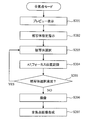
- FIG. 2 is a flowchart illustrating an example of a flow of control processing according to an operation of the operator in an imaging mode in which imaging is performed a plurality of times continuously at different focus positions in the imaging apparatus 10 according to the present embodiment.
- continuous imaging continuous imaging
- continuous imaging while changing the focus position means first imaging at a certain focus position.
- the focus position is moved, and the second imaging is performed at the new focusing position.
- the focusing position is moved and the third imaging is performed at the new focusing position. This means that images are taken sequentially in the order of taking the images.
- an operation in a state where the imaging mode is set to the “all-focus mode” and the all-focus mode is selected will be described.
- an image captured by the imaging unit 101 is displayed as a preview screen on the image display unit 102 (S201).
- an instruction for prompting the operator to specify a subject to be photographed is output to the image display unit 102 (S202).
- the subject selection receiving unit 103-2 of the control unit 103 causes the imaging control unit 103-3 of the control unit 103 to focus on the designated subject.
- a focus control signal is output to the imaging unit 101, and the focus position information that is most in focus detected by the control of the focus control unit 103-1 of the control unit 103 is recorded in the storage device 105 (S204).
- the subject selection accepting unit 103-2 determines whether or not another subject different from the subject selected in S203 is selected (S205). If there is no further subject selection and imaging is selected by the operator, the subject selection ends and the process proceeds to S206.
- the process returns to S203, and the position information that best focuses on the newly designated subject is recorded in the storage device 105.
- S203 to S205 are repeated until the operator finishes selecting the subject.
- a configuration may be adopted in which the focus position of each subject is calculated in S204 after all the subjects that the operator wants to capture are selected in S203, and the process proceeds to S205.
- the process proceeds to S206.
- step S ⁇ b> 206 the image is picked up with the focus at the focus position determined based on the focus position information recorded in the storage device 105. The focus position adjustment and imaging are repeated until all imaging is completed.
- an omnifocal image is generated from the image captured by the image processing unit 104 (S207).
- the preview display in S201 will be described.
- the omnifocal mode When the omnifocal mode is set, first, an image in which the focus is set to a predetermined focus position by autofocus is displayed on the preview screen.
- a subject in S203 which will be described later, it is preferable that all the subjects are in focus so that the operator can identify a plurality of subjects on the preview screen. It is preferable to focus on the near view and the distant view rather than blurring the image or focusing on the distant view and blurring the close view.
- the focus position is determined by calculating the contrast of not only the center of the screen but also the entire screen. The probability of becoming an extreme state can be reduced.
- the all-focus mode is set, if an image focused on a predetermined focus position is displayed, the focus position does not change depending on the scene, so that the focus position becomes extremely close or distant. Can be avoided.
- the depth of field can be increased by reducing the aperture.
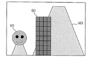
- FIG. 3 shows an example of the preview screen in S201.
- the subjects are arranged in the order of the subject H3 (person), the subject B3 (building), and the subject M3 (mountain) from the front.
- the control device 100 displays an instruction on the image display unit 102 so as to prompt the operator to select a subject to be imaged with focus.
- an instruction to display for example, by displaying “Please select a subject to be imaged”, the operator can be prompted to select a subject.
- the image display unit 102 is a touch panel, it is possible to prompt the operator to select a subject by displaying “Please touch the subject to be imaged”.
- an instruction may be output as an audio signal from a speaker (not shown) mounted on the imaging device 10.
- the operator is prompted to select a subject that reflects the intention (a plurality of subjects that the operator wants to image), the focus position is determined based on the selection information, and continuous imaging is performed. A suitable composite image is synthesized.
- the selection means can be selected by touching the subject displayed on the preview screen by the operator. Even if it is not a touch panel, for example, the cursor is displayed on the preview screen, and the cursor is moved to the target subject using an input device that can operate the cursor up and down, left and right, for example, the cross key. It is only necessary to select with an input device such as a decision button when moving to. These operations are detected by the subject selection receiving unit 103-2.
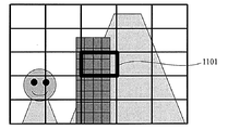
- FIG. 4 shows an image display screen divided into 25 by taking the image display screen of FIG. 3 as an example.
- the operator can select the subject more easily.
- the subject in the region 401 that is, the position where the subject H3 is most focused becomes the focus position of the selected region 401.
- the size of the subject displayed on the image display surface of a digital camera or a mobile phone is small, it is not easy for the operator to select the subject. However, as shown in FIG. Becomes easier. Further, by selecting the position or area selected by the operator in an enlarged manner and selecting the operator on the enlarged display screen, a more suitable subject can be selected.
- FIG. 5 shows an example of a preview screen displayed on the image display surface, which includes subject H5, subject B5, and subject M5. Since the subjects B5 and M5 are adjacent to the subject H5 on the preview screen, it is not easy for the operator to touch only the subject H5 on the image display surface with the finger 601 as shown in FIG. Therefore, when the operator touches the screen, an enlarged view 701 centered on the touched position is displayed as shown in FIG. 7, and the operator selects a subject on the enlarged view 701. The subject displayed in a small size on the preview screen can be selected more accurately.
- the predetermined area may be enlarged centering on the position touched by the operator. When the screen is divided as shown in FIG. 4, the position touched by the operator belongs.
- the area may be enlarged.
- a selection method on the enlarged view for example, there is a method in which the enlarged view is displayed by the first touch, and then the operator's finger is once removed from the screen and the subject is selected by the second touch.
- the enlarged display is made, after the selection is finished, the enlarged display is finished and the screen returns to the preview screen.
- the periphery of the point 801 is a flat region and there are few high frequency components. It is not easy to detect with high accuracy. Therefore, by specifying a region surrounding an arbitrary region instead of a point, such as a region 901A surrounded by a thick line shown in FIG. 9A and a region 901B surrounded by a thick line shown in FIG. 9B, The probability that the high-frequency component of the subject selected by the operator in the designated area is improved, and the focus position can be detected with high accuracy.
- the method for selecting an area can be specified by, for example, moving the screen from the point (start point) on the screen first touched by the operator and returning to the start point so as to surround the predetermined area.
- the focus position may be calculated and stored every time the operator selects one subject, and selection and focus position calculation may be repeated until all subjects are selected.
- the focus position of each subject may be calculated in S204 after all the subjects that the operator wants to image are selected in S203, and the process may proceed to S205.
- the operator can confirm that the selected subject is correctly focused when the focus is on the subject selected by the operator, the operator can be in the case where the focus is at a position different from the operator's intention. This makes it possible to reduce the image pickup at a focus position different from the intended position.
- a subject is selected, and an image focused on the selected subject is displayed on the preview screen.
- the operator can check whether the focus is correctly on the target subject. Further, confirmation is further facilitated by performing an enlarged display as shown in FIG.
- the second subject selection is performed.
- the preview screen when the second subject is selected will be described. If an image in which the first selected subject is in focus is displayed on the preview screen when the second subject is selected, the second subject will be in focus when the foreground or distant view is extremely focused. There is a possibility that the subject that the operator wants to select is so blurred that the subject cannot be identified.
- the preview screen at the time of setting the all-focus mode is a state in which the focus is set from the foreground to the background so that the subject can be identified from the foreground to the background.
- Display for confirmation For example, the first selected subject or region is displayed as a region 1001 indicated by a thick line circle in FIG. 10 superimposed on the preview screen. Further, when the selected area is a divided area as shown in FIG. 4, as shown in FIG. 11, the selected divided area 1101 may be displayed so as to be highlighted by a thick line frame. Good.
- an image focused on the first selected subject may be displayed.
- the display By performing the display as described above, it becomes easy to recognize which subject is selected first when the second subject is selected. Further, when the third subject is selected, the first selected subject and the second selected subject or area are superimposed on the preview screen as shown by areas 1201 and 1202 indicated by thick circles in FIG. Or displayed so as to be highlighted with a thick line frame as in the areas 1301 and 1302 shown in FIG.
- the operator can more suitably select a plurality of subjects by displaying the preview screen so that the selected subject or region can be identified. It becomes possible.
- the configuration in which the focus position of each subject is calculated and stored after all the subjects to be imaged by the operator are selected will be described in more detail.
- the selected subject or region is displayed superimposed on the preview screen so as to be clear.
- the second and third subjects are selected, they are displayed as shown in FIGS.
- the process proceeds to S204, where the focus position of each selected subject is calculated, and the focus position information is stored in the storage device 105.
- the operator can confirm that the desired subject is correctly focused when the focus is in a position different from the operator's intention. This is preferable because imaging at a focus position different from the intention can be reduced.
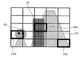
- the selected area is displayed on the preview screen so that the selected area becomes clear, such as areas 1401, 1402, and 1403 shown in FIG.
- it is possible to confirm whether or not the desired subject (B3) is in focus by displaying an image when the area 1401 is focused on the area 1401.
- an area 1402 displays an image when the area 1402 is focused
- an area 1403 displays an image when the area 1403 is focused, so that all subjects selected on one preview screen are displayed.
- the operator can confirm whether (B3, H3, M3) is in focus.
- the images of the selected subjects at the respective focus positions are stored in the storage device 105 when the focus is adjusted, and are displayed on the preview screen after the selection is completed.
- imaging in S206 will be described.
- the image display unit 102 is a touch panel
- a display such as “End selection” is displayed on the preview screen, and it can be determined that the subject selection is ended when the operator touches “End selection”.
- the number of selected subjects is determined in advance, it is possible to shift to imaging when the determined number of selections is reached.
- shifting to imaging the number of images set based on the focus position information recorded in the storage device is continuously imaged.
- imaging is performed at the focus position of each of the plurality of subjects selected by the operator, thereby obtaining an image in which all the subjects that the operator wishes to capture are in focus.
- imaging from the side closer to the focus position to the side farther has the following effects.
- the focus position changes from the first image to the last image in the same direction, so the focus drive time is shorter than when the focus position is changed in random order. is there. That is, it can be said that the time required for continuous imaging is the shortest. By shortening the imaging time, it is possible to minimize movement when shooting a moving subject.
- the shift of corresponding points between a plurality of images can be reduced, and more suitable composition can be performed in the composition processing of S207. Further, even if images are taken in order from the side closer to the focus position to the far side, the change in the focus position is in the same direction.
- S207 all-focus image synthesis
- the focus position is closer to the focus position of other images, and it is easier to search for the corresponding point.
- the imaging order is suitable for the corresponding point search.
- the case where the subjects H3, B3, and M3 in FIG. 3 are imaged will be described as an example.
- the images 1501, 1502 shown in FIG. An image 1503 is obtained.
- searching for corresponding points in the two images 1501 and 1503 the corresponding points are not easily searched because the blurring of the two images is greatly different.
- the degree of similarity is higher than when searching for corresponding points from the two images 1501 and 1503, and the corresponding points are searched. It becomes easy to do.
- the following effects can be obtained by changing the focus position in order from the closest side.
- the subject to be imaged is a moving subject
- there is a time difference between when the focus position is determined and when the image is captured and thus there is a case where the position of the subject is shifted between the time when the focus position is determined and the time when the image is captured.
- a subject close to the subject has a greater amount of movement on the captured image and a change in focus than the subject far away, even with the same amount of movement.
- a subject at a distance of 100 m moves 50 cm forward there is no significant change in focus.
- the focus adjustment may change significantly.
- the foremost focus position is caused by the movement of a close subject by performing continuous shooting after refocusing.
- Focus shift can be reduced.
- the areas 1401, 1402, and 1403 shown in FIG. 14 are selected by the operator, and the respective focus position information is recorded in the storage device 105, and when imaging is performed at three focus positions, the closest focus position is obtained.
- a certain area 1402 is focused again before imaging, the first image is captured at the focus position where the area 1402 is most focused, and the second and third images are recorded in the storage device 105.
- the number of images taken when performing continuous shooting will be described. If the number of images is large, the focus position can be chopped finely, but the time required for imaging increases, the storage device for recording images requires a large capacity, and the amount of processing required for omnifocal image synthesis also increases. There is. On the other hand, when the number is small, the processing amount is lightened, but the operator may not be able to focus on all the subjects that the operator wants to capture.
- the number of continuous shots may be determined in consideration of the above points.
- the following describes how to set the number of images to be captured and the focus position.
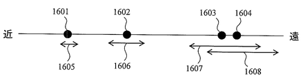
- FIG. 16 shows the focus positions 1601, 1602, 1603, and 1604 and the depths of field 1605, 1606, 1607, and 1608 at the respective focus positions when four subjects located at different distances are selected. ing.
- the depth of field changes depending on the distance from the imaging device, and the depth of field becomes shallower as the distance increases.
- the focus is taken into account the subject position and the depth of field. By resetting the position, suitable imaging can be realized with the set number of sheets. In the case of FIG.
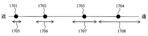
- FIG. 17 shows the depths of field 1705, 1706, and 1707 when four subjects 1701, 1702, 1703, and 1704 located at different distances are selected by the operator and the respective subject positions are focused and imaged. , 1708.
- the difference between FIG. 16 and FIG. 17 is that in FIG. 17, the depths of field at the focus positions of the four subjects do not overlap at all.
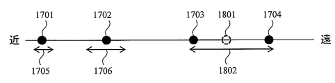
- a new focus position 1801 is set between the subject 1703 and the subject 1704.
- the depth of field at the focus position 1801 is 1802, and both the subject 1703 and the subject 1704 are included in 1802. That is, by resetting the focus position on the subjects 1701, 1702, and 1801, an image in which all of the four subjects 1701-1704 that the operator wants to capture is in focus can be obtained with three images.
- FIG. 19 shows focus positions 1901, 1902, and 1903 and depths of field 1904, 1905, and 1906 at the respective focus positions when three subjects located at different distances are selected.
- the subjects located at the focus positions 1902 and 1903 are both within the depth of field 1908 of 1907 by newly setting the focus position to a point 1907.
- a focused image can be obtained. Therefore, the two focus positions 1902 and 1903 are changed to new focus positions 1907.
- one image pick-up position remaining after resetting is set to a position near the closest focus position 1901, for example, 1909.
- the new focus position is set to 1910, there is an effect that the corresponding point search at the time of synthesizing the omnifocal image becomes easy.
- the operator can set the number of images to be captured according to the number of subjects to be imaged, it is possible to set the number of images appropriately so that there is no excess or deficiency compared to the case where the number of images to be captured is determined in advance. It is. For example, in the case of FIG. 19, if the focus positions are set at two positions 1901 and 1907, focused images of all three subjects to be captured can be obtained. By reducing the number of times of imaging, the imaging time can be shortened, and there are effects of reducing the amount of storage device used for storing images and reducing the amount of processing in subsequent omnifocal image synthesis. Further, as shown in FIG.
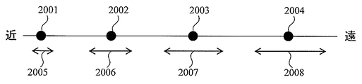
- the number of images set in advance is three, and all the subjects at the four positions 2001, 2002, 2003, 2004 are set regardless of the combination of the three focus positions. If the focus cannot be adjusted, a new fourth focus position is set and four consecutive images are taken, so that an image focused on all selected subjects can be obtained.
- FIG. 21 shows a flowchart of the omnifocal image composition processing.
- S2101 a plurality of images with different focus are corrected.
- the subject size may be different because the angle of view is different.
- the imaging position is shifted due to an operator's hand shake or the like, and when the subject is moving, the position of the moving subject on the image is shifted. Therefore, in S2101, the position shift and size of the subject imaged in common for the plurality of images are corrected.
- the degree of focus of each image is calculated. The degree of focus is the degree of focus.
- As the degree of focus for example, there is a method of calculating a high frequency component. In S2103, a pixel (region) having the highest degree of focus in each corresponding pixel (corresponding region) is selected from each image based on the degree of focus calculated in S2102, and the omnifocal image is synthesized.
- selection is performed by a selection unit that reflects the priority of the operator, and focus control and continuous imaging based on the priority are performed.
- the sentence “Please select in order of image capture” is displayed on the preview screen, so that the priority of the subject selected first is the second highest. Information that the selected subject has the second highest priority can be obtained. Furthermore, not only the priority order but also a selection unit that performs weighting can further select a subject that reflects the user's intention. As a method of performing weighting, there is a method of performing weighting according to the number of selections. In FIG.
- the priority when the priority is the order of the subject H3, the subject M3, and the subject B3, for example, if the image display unit 102 is a touch panel, the subject H3 is touched three times, the subject M3 is touched twice, and the subject B3 Can be set in the order of the subject H3, the subject M3, and the subject B3.
- the priorities of a plurality of subjects are equal, for example, the same weight can be set by setting the same number of times as in a combination of (three times, once, once).
- the strength of the priority when there is a subject with a very high priority, the strength of the priority can be reflected in the weight by combining, for example, (10 times, 2 times, 1 time).
- the priority of the operator changes during the selection of the subject, it is possible to change it with a simple operation without resetting the preset priority from the beginning. For example, after the three subjects H3, M3, and B3 in FIG. 3 are once weighted with a combination of (three times, two times, and once), the subject B3 having the lowest priority has the highest priority. If the third subject B3 is touched three more times, the number of touches of each subject becomes a combination of (three times, two times, four times), and the third subject B3 has the highest priority. Can be set.
- the weighting may be set by displaying a slider bar 2201 as shown in FIG. 22 at the position or area selected by the operator and operating the slider 2202.
- the priority can be set for each subject by one operation regardless of the priority. Even when the priority is changed, it is only necessary to select the subject to be changed again and operate the slider, and the setting can be changed with a very simple operation.
- a weight setting method as shown in FIG. 23 may be used. The numbers from 0 to 7 shown in FIG. 23 indicate weights. When the operator selects a subject, the weight setting screen shown in FIG. 23 is displayed, and the weights may be selected. Similar to the slider bar, it can be set by a simple operation, and the setting can be changed or canceled (for example, set to 0) by a simple operation.
- the operation becomes easier if the operator can recognize the weights already input. Therefore, in addition to the display indicating that the selection has been made as shown in FIGS. 12 and 13, for example, by displaying the number of input weights in the vicinity of the selected region, the weight value can be given to the operator. Can be recognized. Further, when the selected area is displayed surrounded by a thick line, it is easy to recognize even if the thickness of the thick line is increased in descending order of weight. It can also be recognized by changing the color of the display indicating that it has been selected. For example, if the color of the thick line indicating selection is changed to red, yellow, and blue in descending order of weight, it can be recognized.
- FIG. 24 shows four subjects 2401, 402, 2403, and 2404 selected by the operator, and depths of field 2405, 2406, 2407, and 2408 when images are taken at the respective positions.
- the number of captured images is set to 3
- the priority of the selected subject is 2403, 2401, 2402, 2404 in descending order.
- the subjects 2403 and 2404 are located at a close distance, and by capturing images at a focus position where the two subjects are both within one depth of field, an image in which the two subjects are in focus can be obtained by one imaging. be able to.
- setting based on priority is performed.
- the position is set so that 2403 is imaged as clearly as possible. That is, the focus position is set as close to the subject 2403 as possible.
- the positions 2409 as a new focus position
- the subjects 2403 and 2404 both enter one depth of field 2410, and the subject 2403 is positioned at the approximate center of the depth of field 2410. In other words, a clearer image can be obtained than when focusing is performed between 2403 and 2404.
- FIG. 25 shows subjects 2501 and 2502 selected by the operator, and depths of field 2503 and 2504 corresponding to the subjects.
- the number of captured images is set to 3, and the priority of the selected subject is in the order of 2502, 2501 from the highest. Since the number of selected subjects is two for three images, two of the three images are focused on each subject, and the remaining one is given priority. Can be set based on.
- the focus position for the remaining one focus is set near the subject 2502 with high priority, such as a position 2505 shown in FIG. By capturing images twice at close focus positions, it is possible to increase the probability that the subject 2502 can be focused and imaged.
- the remaining one is imaged at the same position as the subject 2502, noise can be reduced. If two images are taken at the same focus position, two images with the same in-focus degree can be obtained. If they are averaged, the in-focus degree is equivalent, so there is no blurring and the noise reduction effect by averaging is achieved. can get. Similarly, if the number of images to be captured is six and the number of selected subjects is three, the focus position of six times of imaging is set near the subject with the highest priority, twice and the second priority is the second priority. If imaging is performed in the vicinity of a high subject in accordance with the subject having the lowest priority at least once, continuous imaging can be performed in which the probability of successful imaging reflects the operator's intention.
- the priority By setting the focus position in order of priority so that the subject with a high priority is focused, continuous imaging with a focus on the subject with a high priority can be performed.
- any one of the images that the subject that the operator wants to capture is continuously captured based on the subject selection information input by the subject selection unit that reflects the priority of the operator.
- All the subjects that the operator wants to capture are set by setting the focus position so that subjects with high priority of the operator are captured as images with high focus in the image. In particular, it is possible to provide a clear image with a high degree of focus on a high priority subject.
- the present invention includes the following disclosure.
- An imaging unit that captures an image, a focus control unit that controls the focus of the imaging unit, a subject selection unit that can select a subject, and an image processing unit that performs image processing on an image captured by the imaging unit
- An imaging device comprising: The imaging unit captures a plurality of images whose focus is changed by the focus control unit, At least one of the plurality of images is captured based on a focus position of the subject selected by the subject selection unit, The image processing unit generates an image in which a depth of field is enlarged from the captured one image from the plurality of images.
- At least one of the plurality of images is picked up at a focus position positioned between the focus positions of the plurality of subjects selected by the subject selection receiving unit.
- the subject selection accepting unit is a subject selecting unit that accepts and reflects the priority of the operator, and at least one of the plurality of images is a subject with high priority accepted by the subject selection accepting unit.
- the imaging apparatus according to (1) wherein imaging is performed at a focus position where a degree of in-focus is high.
- the focus control unit controls the focus so that the movement directions of the respective focus positions when capturing the plurality of images are the same direction. Any one of (1) to (3) Or the imaging device according to claim 1.
- the image processing unit generates, from the plurality of images, an image in which the depth of field is expanded from the captured one image, and any one of (1) to (4) The imaging device described.
- An imaging unit that captures an image, a focus control unit that controls the focus of the imaging unit, a subject selection unit that can select a subject, and an image processing unit that performs image processing on an image captured by the imaging unit.
- An imaging method using an imaging apparatus comprising: The imaging unit captures a plurality of images whose focus is changed by the focus control unit, At least one of the plurality of images is captured based on a focus position of the subject selected by the subject selection unit, The imaging method, wherein the image processing unit generates, from the plurality of images, an image in which a depth of field is expanded from the captured one image.
- a computer-readable recording medium for recording the program according to (7) A computer-readable recording medium for recording the program according to (7).
- Each component of the present invention can be arbitrarily selected, and an invention having a selected configuration is also included in the present invention.
- a program for realizing the functions described in the present embodiment is recorded on a computer-readable recording medium, and the program recorded on the recording medium is read into a computer system and executed to execute processing of each unit. May be performed.
- the “computer system” here includes an OS and hardware such as peripheral devices.
- the “computer system” includes a homepage providing environment (or display environment) if a WWW system is used.
- the “computer-readable recording medium” means a storage device such as a flexible disk, a magneto-optical disk, a portable medium such as a ROM and a CD-ROM, and a hard disk incorporated in a computer system. Furthermore, the “computer-readable recording medium” dynamically holds a program for a short time like a communication line when transmitting a program via a network such as the Internet or a communication line such as a telephone line. In this case, a volatile memory in a computer system serving as a server or a client in that case, and a program that holds a program for a certain period of time are also included.
- the program may be a program for realizing a part of the above-described functions, or may be a program that can realize the above-described functions in combination with a program already recorded in a computer system. At least a part of the functions may be realized by hardware such as an integrated circuit.
- DESCRIPTION OF SYMBOLS 10 ... Imaging device, 100 ... Control apparatus, 101 ... Imaging part, 102 ... Image display part, 103 ... Control part, 103-1 ... Focus control part, 103-2 ... Subject selection reception part, 103-3 ... Imaging control part 104: Image processing unit, 105: Storage device.
Landscapes
- Engineering & Computer Science (AREA)
- Multimedia (AREA)
- Signal Processing (AREA)
- Theoretical Computer Science (AREA)
- Computing Systems (AREA)
- Physics & Mathematics (AREA)
- General Physics & Mathematics (AREA)
- Studio Devices (AREA)
Abstract
画像を撮像する撮像部と、前記撮像部のフォーカスを制御するフォーカス制御部と、被写体の選択操作を受け付ける被写体選択受付部と、前記撮像部が撮像した画像を画像処理する画像処理部と、を備える撮像装置であって、前記撮像部は、前記フォーカス制御部によりフォーカスを変えた複数の画像を撮像し、前記複数の画像のうち少なくとも1つは、前記被写体選択受付部により受け付けた選択された被写体のフォーカス位置に基づいて撮像し、前記画像処理部は、前記撮像した1つの画像より被写界深度を拡大した画像を、前記複数の画像から生成することを特徴とする撮像装置。
Description
本発明は、被写界深度の深い画像を撮影することができる撮像装置に関する。特に、複数の画像から出力画像を生成する撮像装置に関する。
フォーカスの合った鮮明な画像を撮像するための技術として、自動的に所定位置にフォーカスを合わせるオートフォーカス技術が知られている。オートフォーカス技術の方式には、位相差方式やコントラスト方式など様々な方式が知られており、近年のコンパクトデジタルカメラや携帯電話等に搭載されるカメラの多くには、コントラスト方式のオートフォーカスが搭載されている。コントラスト方式は、フォーカスレンズを動かしながら撮像素子に映った映像の高周波数成分が大きい(コントラストが高い)位置を探してフォーカスを合わせる方式であり、映像の中央付近の高周波数成分を算出してフォーカス位置を決定したり、映像全体の高周波数成分を算出してフォーカス位置を決定したり、タッチパネル上で操作者により選択された被写体の高周波数成分を算出してフォーカス位置を決定したりする。オートフォーカスにより、操作者(撮影者)自身がフォーカスを調整する必要がなくなり、より簡単な操作でフォーカスの合った鮮明な画像を撮像することが可能となる。
しかしながら、異なる距離に複数の被写体が存在する場合、オートフォーカスにより一方の被写体にフォーカスを合わせると、距離の異なる他方の被写体にはフォーカスが合わない可能性がある。
そこで、操作者が撮像したい被写体が複数存在し、各被写体が異なる距離に位置する場合において、複数の被写体すべてにフォーカスの合った鮮明な画像を得るための技術が開発されている。例えば、下記特許文献1では、異なるフォーカス位置で複数の画像を連続的に撮像し、各画像に共通する複数の被写体部それぞれについて、最も鮮明に撮像された画像から抽出し合成することで、複数の被写体がすべて鮮明な画像を得ると記載されている。
しかしながら、特許文献1に記載の撮像方法では、操作者がフォーカスを合わせて鮮明に撮像したい被写体が複数のフォーカス位置のいずれにも位置しない可能性があり、そのような場合、目的の被写体が不鮮明になるという課題がある。図26は、4つの被写体2601,2602、2603、2604の位置と、連続して3回撮像する場合のフォーカス位置2605、2606、2607を示している。図26の2605、2606、2607上に示す矢印は、各フォーカス位置で撮像する場合の被写界深度を示している。図26は、被写体2601、2602、2604の3つは、3つのフォーカス位置のいずれかの被写界深度内に位置しているためフォーカスの合った鮮明な画像が得られるが、被写体2603はいずれのフォーカス位置の被写界深度内にも位置していないため、撮像する3枚のいずれの画像においてもフォーカスの合った鮮明な画像として撮像されない。
図27は、図26の3つのフォーカス位置2605、2606、2607に加え、新たにフォーカス位置2701、2702、2703、2704を加えた図である。図27に示すように、撮像枚数を増やし、フォーカス位置を細かく変化させて撮像すれば、操作者が撮像したい被写体がフォーカスの合った鮮明な画像として撮像される確率は増加する。しかしながら、撮像する枚数が増えると、撮像に要する時間が長くなり、動いている被写体を撮影する場合における複数画像間での対応点のずれが大きくなる。その結果、対応点探索が困難になり、画像の合成が困難になるため、撮像枚数を増やせば被写界深度の深い好適な画像が得られるとは限らない。
本発明は上記の点に鑑みてなされたものであり、操作者の意図を反映するフォーカス位置で撮像し、目的の被写体にフォーカスの合った鮮明な画像を得ることができる撮像装置を提供することを課題とする。
本発明の一観点によれば、画像を撮像する撮像部と、前記撮像部のフォーカスを制御するフォーカス制御部と、被写体の選択操作を受け付ける被写体選択受付部と、前記撮像部が撮像した画像を画像処理する画像処理部と、を備える撮像装置であって、前記撮像部は、前記フォーカス制御部によりフォーカスを変えた複数の画像を撮像し、前記複数の画像のうち少なくとも1つは、前記被写体選択受付部により受け付けた選択された被写体のフォーカス位置に基づいて撮像することを特徴とする撮像装置が提供される。
上記により、操作者の意図を反映する被写体選択手段により選択された複数の被写体を、選択情報に基づくフォーカス位置で撮像することができる。いずれか一方のフォーカス位置で撮像するだけで、選択された2つの被写体にフォーカスが合った画像を得ることができる。
この際、設定された撮像枚数に対し、それよりも多い数の被写体が操作者に選択されている場合、被写体位置と被写界深度を考慮してフォーカス位置を再設定することで、設定された枚数で好適な撮像を実現することができる。
再設定は、フォーカス位置での被写界深度が重複している場合には、いずれか一方又はその間に再設定し、被写体のフォーカス位置での被写界深度が全く重複していない場合には、被写体間に新たにフォーカス位置を設定するようにすると良い。
前記被写体選択受付部は、操作者の優先度を受付け、前記複数の画像のうち少なくとも1つは、前記被写体選択受付部により受け付けられた優先度の高い被写体の合焦度が高くなるフォーカス位置で撮像することを特徴とする。
選択されたすべての被写体にフォーカスを合わせて撮像するために最低限必要なフォーカス位置が、設定された撮像枚数より少ない場合においては、フォーカス位置を新たに点に設定することで、1回の撮像で2つの被写体にフォーカスの合った画像が得られるようにする。
前記複数の画像のうち少なくとも1つは、前記被写体選択受付部により選択が受付された複数の被写体のフォーカス位置間に位置するフォーカス位置で撮像することを特徴とする。
前記フォーカス制御部は、前記複数の画像を撮像する際のそれぞれのフォーカス位置の移動方向が同一方向になるようにフォーカスを制御することを特徴とする。
前記画像処理部は、前記撮像した1つの画像より被写界深度を拡大した画像を、前記複数の画像から生成することを特徴とする。
本明細書は本願の優先権の基礎である日本国特許出願2013-082457号の明細書および/または図面に記載される内容を包含する。
本発明によれば、選択された複数の被写体にフォーカスの合った鮮明な画像を得ることができる。
(第1の実施形態)
以下、図面を参照しながら本発明の実施形態について説明する。図1は、本実施形態に係る撮像装置10の構成を示す概略図である。
以下、図面を参照しながら本発明の実施形態について説明する。図1は、本実施形態に係る撮像装置10の構成を示す概略図である。
撮像装置10は、制御装置100、撮像部101、画像表示部102を含んで構成される。制御装置100は、制御部103、画像処理部104、記憶装置105を含んで構成される。
撮像部101は、CCD(Charge Coupled Device、電荷結合素子)等の撮像デバイスやレンズ、レンズ駆動部などを含んで構成される。
画像表示部102は、制御装置100から入力された出力画像信号が示す画像を表示する。画像表示部102は、例えば、液晶ディスプレイ(Liquid Crystal Display)である。画像表示部102は、タッチパネル機能を備えていてもよい。タッチパネルとは、表示画面に表示された絵や領域に触れることを感知して外部へ情報信号として出力する装置である。タッチパネルには、操作した位置の電圧を感知する抵抗膜方式や、指先と導電膜の間での静電容量の変化を捉えて位置を検出する静電容量方式などがあり、操作者の画面上での位置情報や操作に対応した動作を行なう。
制御部103は、撮像部101のレンズ(図示せず)の駆動や、電源ボタンやシャッタボタンなどの入力装置(図示せず)からの入力信号の受信、画像表示部102への画像表示などの制御を行う。制御部103は、撮像装置10に備えられたCPU(Central Processing Unit)、GPU(Graphics Processing Unit)等のハードウェアがプログラムを実行することで実現される。
制御部103は、図1(b)に示すように、フォーカス制御部103-1と、被写体選択受付部103-2と、撮像制御部103-3とを有している。画像処理部104は、入力された複数の入力画像に対して鮮鋭度などを解析し、解析結果に基づいて1枚の画像を合成する。また、画像処理部104は、例えば、ASIC(Application Specific Integrated Circuit)、FPGA(Field Programmable Gate Array)等のハードウェアで実現することができる。
図2は、本実施形態に係る撮像装置10において、異なるフォーカス位置で複数回の撮像を連続して行う撮像モードにおける、操作者の操作に応じた制御処理の流れの一例を示すフローチャートである。なお、「連続して撮像(連続撮像)」とは、複数回の撮像を短時間で行うことを意味し、「フォーカス位置を変えながら連続撮像する」とは、あるフォーカス位置で1回目の撮像を行い、1回目の撮像が終わると、フォーカス位置を移動し、新たなフォーカス位置で2回目の撮像を行い、2回目の撮像が終わると、フォーカス位置を移動し、新たなフォーカス位置で3回目の撮像を行う、という順に、順次撮像を行うことを意味する。以下では、この撮像モードを「全焦点モード」とし、全焦点モードが選択された状態での操作について述べる。
全焦点モードに設定されると、撮像部101で撮影した画像が画像表示部102にプレビュー画面として表示される(S201)。次に、画像表示部102に、操作者に撮影したい被写体の指定を促す指示を出力する(S202)。被写体選択に関する操作者からの入力が検知されると(S203)、制御部103の被写体選択受付部103-2により、指定された被写体にフォーカスが合うよう制御部103の撮像制御部103-3から撮像部101へフォーカス制御信号が出力され、制御部103のフォーカス制御部103-1が制御することにより検出された最もフォーカスの合うフォーカス位置情報を記憶装置105に記録する(S204)。次に、S203で選択された被写体とは異なる被写体が更に選択されるか否かが被写体選択受付部103-2により判断される(S205)。更なる被写体の選択がなく、操作者によって撮像が選択される場合は、被写体選択終了となり、S206へ進む。
新たに被写体が選択される場合は、S203に戻り、新たに指定された被写体に最もフォーカスの合う位置情報を記憶装置105に記録する。
以上のように、操作者の被写体選択が終了するまでS203からS205を繰り返す。なお、S203からS205を繰り返す構成ではなく、S203で操作者が撮像したい被写体がすべて選択されてから、S204でそれぞれの被写体のフォーカス位置を算出し、S205に進む構成でもよい。S205で被写体選択が終了した場合は、S206に進む。S206では、記憶装置105に記録されたフォーカス位置情報に基づいて決定されたフォーカス位置にフォーカスを合わせて撮像する。すべての撮像が終わるまで、フォーカス位置の調整と撮像を繰り返す。撮像が終了すると、画像処理部104で撮像された画像から全焦点画像が生成される(S207)。
次に、図2に示したフローチャートの各ステップの詳細について述べる。まず、S201におけるプレビュー表示について述べる。全焦点モードに設定されると、最初はオートフォーカスでフォーカスを所定のフォーカス位置に合わせた画像をプレビュー画面に表示する。後述するS203で被写体を選択する際、操作者がプレビュー画面上で複数の被写体を識別できる程度にはすべての被写体にフォーカスが合っている方が好適であるため、極端に近景にフォーカスが合い遠景がボケている状態や、極端に遠景にフォーカスが合い近景がボケている状態よりは、近景から遠景までフォーカスが合っている状態の方が好ましい。被写体を識別できる程度に近景から遠景までフォーカスの合っている状態を実現するために、例えば、オートフォーカス時に、画面中央だけでなく画面全体のコントラストを算出してフォーカス位置を決定することで上述の極端な状態になる確率を低減することができる。また、全焦点モード設定時に、あらかじめ決められた所定のフォーカス位置にフォーカスを合わせた画像を表示すれば、シーンに依ってフォーカス位置が変化しないため、極端にフォーカス位置が近景や遠景となることを避けることができる。また、絞りを絞ることで被写界深度を深くすることができる。
図3は、S201のプレビュー画面の一例を示している。図3では、手前から被写体H3(人物)、被写体B3(建物)、被写体M3(山)の順に被写体が並んでいる。プレビュー状態において、制御装置100は、操作者に、フォーカスを合わせて撮像したい被写体の選択を促すよう、画像表示部102に指示を表示する。表示する指示としては、例えば、「撮像したい被写体を選択して下さい」と表示することで、操作者に被写体選択を促すことができる。画像表示部102がタッチパネルであれば、「撮像したい被写体にタッチして下さい」と表示することで、操作者に被写体選択を促すことができる。また、選択できる被写体の数に上限を設けることで、操作者の意図をより反映することができる。例えば、「撮影したい被写体上位3つを選択して下さい」と表現することで、単に選択するより操作者の意図を反映する被写体選択を促すことができる。上限を設けることで、操作者の意図を重視するフォーカス位置設定を行うことができるとともに、選択開始から選択終了までに要する時間が短縮される効果が期待でき、後述する全焦点画像合成に好適である。また、撮像装置10に搭載されているスピーカ(図示せず)から音声信号として指示を出力してもよい。本実施の形態では、操作者に意図(操作者が撮像したい複数の被写体)を反映する被写体選択を促し、その選択情報に基づいてフォーカス位置を決定し連続撮像を行うことで、操作者の意図にそぐう好適な合成画像を合成する。
次に、S203における操作者の被写体選択方法について述べる。
選択手段は、例えば、画像表示部102がタッチパネルであれば、プレビュー画面に表示されている被写体に操作者が触れることで選択することができる。また、タッチパネルでなくても、例えば、プレビュー画面上にカーソルを表示させ、カーソルを上下左右に操作可能な入力装置、例えば十字キーで、目的の被写体までカーソルを移動し、カーソルが目的の被写体上に移動した時点で決定ボタンなどの入力装置により選択すればよい。これらの操作を、被写体選択受付部103-2により検出する。
図4は、図3の画像表示面を例として25分割した画像表示面である。被写体選択時に、プレビュー画面を分割することで、操作者がより簡単に被写体を選択することができる。被写体H3を選択する場合、図4に太線で示す領域401を選択すれば、領域401内にある被写体、すなわち、被写体H3に最もフォーカスの合う位置が選択された領域401のフォーカス位置となる。デジタルカメラや携帯電話などの画像表示面に表示される被写体のサイズが小さい場合、その被写体を操作者が選択することは容易でないが、図4に示すように、領域を選択することで、操作が簡単になる。また、操作者が選択した位置または領域を拡大表示し、拡大表示画面上で操作者が選択する構成とすることで、更に好適な被写体選択が可能となる。図5は、画像表示面に表示されたプレビュー画面の一例を示しており、被写体H5、被写体B5、被写体M5が含まれる。プレビュー画面上では被写体H5に被写体B5、M5が隣接しているため、図6に示すように、操作者が指601で画像表示面上の被写体H5のみに触れることは容易ではない。そこで、操作者が画面上に触れると、図7に示すように、触れた位置を中心とする拡大図701を表示し、拡大図701上で操作者が被写体を選択する構成とすることで、プレビュー画面上に小さく表示される被写体を、より正確に選択することができる。図7に示す拡大図701は、操作者が触れた位置を中心として所定領域を拡大してもよいし、図4のように画面が分割されている場合は、操作者が触れた位置が属する領域を拡大してもよい。拡大図上での選択方法は、例えば、1度目のタッチで拡大図が表示され、次に、操作者の指が一度画面上から離れ、2度目のタッチで被写体を選択する方法がある。拡大表示した場合は、選択終了後、拡大表示を終了し、プレビュー画面に戻る。
また、操作者に任意の領域を選択させることで、さらに好適な被写体選択が可能となる。図8において、操作者が被写体M3を選択する際、点801を指定した場合、点801の周辺は平坦領域であり高周波数成分が少ないため、コントラスト方式で点801に最もフォーカスの合うフォーカス位置を精度良く検出することは容易ではない。そこで、図9(a)に示す太線で囲まれた領域901Aや図9(b)に示す太線で囲まれた領域901Bのように、点ではなく、任意の領域を囲むようにして指定することで、指定領域に操作者が選択した被写体の高周波数成分を含む確率が向上し、精度良くフォーカス位置を検出することができる。領域の選択方法は、例えば、操作者が最初にタッチした画面上の点(始点)から画面上を動かし、所定領域を囲むように始点に戻る操作をすることで指定することができる。
次に、S203からS205の流れについて述べる。S203からS205では、上述のように、操作者が1つ被写体を選択する毎にフォーカス位置を算出して記憶し、すべての被写体選択が終わるまで、選択とフォーカス位置算出とを繰り返してもよいし、S203で操作者が撮像したい被写体がすべて選択されてから、S204でそれぞれの被写体のフォーカス位置を算出し、S205に進む構成でもよい。
操作者が1つ被写体を選択する毎にフォーカス位置を算出して記憶し、すべての被写体選択が終わるまで、選択とフォーカス位置算出を繰り返す構成について、更に詳しく説明する。
操作者に選択された被写体にフォーカスを合わせた際、選択された被写体に正しくフォーカスが合っているかを操作者が確認できれば、操作者の意図とは異なる位置にフォーカスが合っている場合に操作者に認識させることができ、意図とは異なるフォーカス位置での撮像を低減することができ好適である。
そこで、本実施の形態では、被写体が選択され、選択された被写体にフォーカスを合わせた画像をプレビュー画面に表示する。プレビュー画面に表示することで、フォーカスが目的の被写体に正しく合っているかを操作者が確認することができる。また、図7に示したような拡大表示をすることで、更に確認が容易になる。最初の被写体選択とフォーカス位置算出が終わると、2つ目の被写体選択となる。ここで、2つ目の被写体選択時のプレビュー画面について述べる。2つ目の被写体選択時のプレビュー画面に、最初に選択された被写体にフォーカスが合っている画像が表示されていると、極端に近景や遠景にフォーカスが合っている場合、2つ目の被写体として操作者が選択したい被写体が識別できないほどボケている可能性がある。そこで、2つ目の被写体選択時には、全焦点モード設定時のプレビュー画面に戻す方が被写体選択という点で好ましい。全焦点モード設定時のプレビュー画面とは、前述の、近景から遠景まで被写体を識別できる程度に近景から遠景までフォーカスの合っている状態である。ただし、最初のプレビュー画面に戻すと、どの被写体が選択済みであるかを画面上からは確認できなくなり、操作者が覚えておく必要が生じるため、選択済みである被写体を操作者が画面上で確認できるよう表示を行う。例えば、最初に選択された被写体または領域を、図10に太い線の円で示す領域1001としてプレビュー画面に重畳して表示する。また、選択された領域が図4で示したような分割された領域である場合には、図11に示すように、選択された分割領域1101を太い線の枠で強調するよう表示してもよい。また、選択された分割領域のみをプレビュー画面に戻さず、最初に選択された被写体にフォーカスを合わせた画像を表示してもよい。
以上のような表示を行うことで、2つ目の被写体選択時に、最初にどの被写体を選択したかを認識しやすくなる。更に、3つ目の被写体選択時には、最初に選択された被写体と2つ目に選択された被写体または領域を、図12に示す太い線の円で示す領域1201、1202のようにプレビュー画面に重畳して表示したり、図13に示す領域1301、1302のように太い線の枠で強調するよう表示したりしてもよい。
以上説明したように、被写体選択とフォーカス位置算出を繰り返す構成において、選択済みの被写体または領域を識別できるようにプレビュー画面を表示することで、操作者がより好適に複数の被写体を選択することが可能となる。
次に、操作者が撮像したい被写体がすべて選択されてから、ぞれぞれの被写体のフォーカス位置を算出して記憶する構成について、更に詳しく説明する。最初の被写体が選択されると、図10や図11に示したように、選択された被写体または領域が明確になるようプレビュー画面上に重畳して表示する。2つ目、3つ目の被写体が選択された場合も同様に、図12や図13に示したように表示する。そして、被写体選択が終わると、S204に進み、選択されたそれぞれの被写体のフォーカス位置を算出し、フォーカス位置情報を記憶装置105に保存する。フォーカス位置の算出を終えた際、所望の被写体に正しくフォーカスが合っているかを操作者が確認できる方が、操作者の意図とは異なる位置にフォーカスが合っている場合に操作者に認識させることができ、意図とは異なるフォーカス位置での撮像を低減することができ好適である。
そこで、フォーカス位置の算出を終えると、図14に示す領域1401、1402、1403のように、選択された領域が明確になるようプレビュー画面に表示する。このとき、領域1401には領域1401にフォーカスを合わせた際の画像を表示することで、所望の被写体(B3)にフォーカスが合っているかを確認することができる。同様に、領域1402には領域1402にフォーカスを合わせた際の画像、領域1403には領域1403にフォーカスを合わせた際の画像をそれぞれ表示することで、1つのプレビュー画面上で選択したすべての被写体(B3、H3、M3、)にフォーカスが合っているかを操作者が確認することができる。選択された被写体のそれぞれのフォーカス位置での画像は、フォーカスを合わせた際に記憶装置105に保存しておき、選択終了後にプレビュー画面に表示する。
次に、S206の撮像について述べる。S205からS206への移行は、例えば、操作者によってシャッタボタンが押された場合に被写体選択終了と判断してS206の撮像に移行することができる。また、画像表示部102がタッチパネルであれば、プレビュー画面に「選択終了」などの表示を行い、操作者が「選択終了」に触れたら被写体選択終了と判断することができる。また、予め被写体選択数が決まっている場合は、決められた選択回数に達した時点で撮像に移行することができる。撮像に移行すると、記憶装置に記録されたフォーカス位置情報に基づいて設定された枚数を連続撮像する。選択、フォーカス合わせ、撮像の順に、1つの被写体を選択する度に撮影まで行うと、被写体を選択している間に被写体が動いてしまうため、撮像の前にすべてのフォーカス位置を設定しておき、その設定に基づいて連続撮像することで、撮像画像間の時間差を減少させることができ、後述のS207(全焦点画像合成)に好適である。
次に、フォーカス位置を変えながら連続撮像する際の、撮像順序について述べる。本実施の形態では、操作者により選択された複数の被写体それぞれのフォーカス位置で撮像を行うことで、操作者が撮像したい被写体すべての被写体にフォーカスの合った画像を得る。フォーカスを変えて撮像する際、フォーカス位置の近い側から遠い側に撮像することで以下の効果がある。フォーカス位置の近い側から順に撮像すると、最初の撮像から最後の撮像まで、フォーカス位置の変化が同一方向となるため、ランダムな順にフォーカス位置を変化させる場合と比べ、フォーカス駆動時間が短くなる効果がある。つまり、連続撮像に要する時間が最も短くなる順序と言える。撮像時間が短くなることで、動いている被写体を撮影する場合における動きを最小限に抑えることができる。つまり、複数画像間での対応点のずれを小さくすることができ、S207の合成処理においてより好適な合成が可能となる。また、フォーカス位置の近い側から遠い側に順に撮像しても、フォーカス位置の変化が同一方向であるため、近い側から遠い側の順で撮像する場合と同様の効果がある。
また、フォーカス位置の変化を同一方向にすることで、更に以下の効果がある。後述のS207(全焦点画像合成)において、合成に用いる複数の画像の対応点を探索する必要があり、対応点を探索する場合、複数の画像間の類似度が高い方が探索しやすくなる。例えば、近景にフォーカスを合わせて遠景がボケている画像と遠景にフォーカスを合わせて近景がボケている画像では、対応する領域のフォーカスの合い具合が全く異なるため、対応点探索が容易ではない場合がある。上記の点を考慮すると、フォーカス位置を同一方向に変化させて撮像する場合、連続して撮像する2枚を比較すると、フォーカス位置が他の画像のフォーカス位置に比べ近く対応点を探索しやすく、また、撮像間隔も短いことから、被写体位置のずれも小さいことから、対応点探索に適した撮像順序である。図3の被写体H3、B3、M3を撮像する場合を例に説明すると、近い側から被写体H3、B3、M3の順で撮像すると、ぞれぞれの画像は図15に示す画像1501、画像1502、画像1503になる。画像1501と画像1503との2つの画像で対応点を探索する場合、両画像のボケ方が大きく異なるため対応点探索が容易ではない。一方、画像1502を基準に、画像1501、画像1503との対応点を探索する場合、画像1501と画像1503の2枚の画像から対応点を探索する場合に比べ類似度が高く、対応点を探索しやすくなる。
近い側から順にフォーカス位置を変えて撮像することで、更に以下の効果がある。撮像する被写体が動く被写体である場合、フォーカス位置決定時と撮像時とで時間差があるため、フォーカス位置を決定してから撮像するまでの時間に被写体の位置がずれる場合がある。特に、近くにある被写体は、遠くにある被写体に比べ、同じ動き量であっても撮像される画像上での移動量や、フォーカスの合い具合の変化が大きくなる。例えば、距離100mにある被写体が50cm手前に移動してもフォーカスの合い具合に大きな変化はないが、距離1mにある被写体が50cm手前に移動すると、フォーカスの合い具合が大きく変化する可能性がある。近い側からフォーカス位置を変えて撮像する場合、被写体選択終了から最も近い側での撮像までの時間を最も短くすることができ、上述の被写体の動きに起因するフォーカスのずれを低減することができる。
上述の点を考慮し、撮像前に設定された複数のフォーカス位置のうち、最も手前のフォーカス位置に関しては、再度フォーカス合わせをしてから連写撮像を行うことで、近い被写体の動きに起因するフォーカスのずれを低減することができる。例えば、図14で示した領域1401、1402、1403が操作者により選択され、それぞれのフォーカス位置情報が記憶装置105に記録されており、3つのフォーカス位置で撮像する際、最も手前のフォーカス位置である領域1402については、撮像前に再度フォーカス合わせを行い、領域1402に最もフォーカスの合うフォーカス位置で1枚目の撮像を行い、2枚目、3枚目の撮像は、記憶装置105に記録されたフォーカス位置に設定して撮像を行うことで、被写体の動きに起因するフォーカスのずれを更に低減することができる。
次に、連写撮像を行う際の撮像枚数について述べる。撮像枚数が多いとフォーカス位置を細かく刻んで撮像できるが、撮像に要する時間が長くなり、画像を記録する記憶装置も大きな容量が必要になり、全焦点画像合成に要する処理量も多くなるという課題がある。一方、枚数が少ないと、処理量は軽くなるが、操作者が撮像したい被写体すべてにはフォーカスを合わせられない場合がある。以上の点を考慮して連写する枚数を決定すればよい。
以下では、撮像枚数とフォーカス位置の設定方法について述べる。
まず、撮像枚数が固定されている場合の撮像方法について述べる。ここでは、撮像枚数が3枚に設定されているとする。図16は、異なる距離に位置する4つの被写体が選択された場合における、そのフォーカス位置1601、1602、1603、1604と、それぞれのフォーカス位置での被写界深度1605、1606、1607、1608を示している。被写界深度は撮像装置からの距離によって変化し、近景ほど被写界深度が浅くなっている。図16にように、設定された撮像枚数(3枚)に対し、選択された被写体の数(4つ)が操作者に選択されている場合、被写体位置と被写界深度を考慮してフォーカス位置を再設定することで、設定された枚数で好適な撮像を実現する。図16の場合は、被写界深度1607または被写界深度1608の一方に、被写体1603と被写体1604がともに含まれるため、いずれか一方のフォーカス位置で撮像するだけで、選択された2つの被写体にフォーカスが合った画像を得ることができる。つまり、フォーカス位置1601、1602、1603の3つフォーカス位置で撮像することで、4つの被写体すべてにフォーカスの合った画像を得ることができる。また、図17は、異なる距離に位置する4つの被写体1701、1702、1703、1704が操作者に選択され、それぞれの被写体位置にフォーカスを合わせて撮像する場合の被写界深度1705、1706、1707、1708を示している。図16と図17の違いは、図17では、4つの被写体のフォーカス位置での被写界深度が全く重複していない点である。図17の場合においては、4つのフォーカス位置のうち3つを選択すると、それぞれの被写界深度が重複していないため、選択されない被写体については、フォーカスの合った画像が得られない。そこで、図18に示すように、被写体1703と被写体1704の間に新たにフォーカス位置1801を設定する。フォーカス位置1801の被写界深度は1802であり、1802には被写体1703と被写体1704が共に含まれる。すなわち、被写体1701、1702、1801にフォーカス位置を再設定することで、3枚の撮像で、操作者が撮像したい4つの被写体1701-1704のすべてにフォーカスが合った画像が得られることになる。
次に、選択されたすべての被写体にフォーカスを合わせて撮像するために最低限必要なフォーカス位置が、設定された撮像枚数より少ない場合について述べる。図19は、異なる距離に位置する3つの被写体が選択された場合における、そのフォーカス位置1901、1902、1903と、それぞれのフォーカス位置での被写界深度1904、1905、1906を示している。図19の場合、フォーカス位置1902と1903に位置する被写体は、フォーカス位置を新たに点1907に設定することで、共に1907の被写界深度1908内となるため、1回の撮像で2つの被写体にフォーカスの合った画像が得られる。そこで、2つのフォーカス位置1902と1903を、新たなフォーカス位置1907に変更する。そして、設定された撮像枚数3枚のうち、再設定により残された1つの撮像位置を最も近い側のフォーカス位置1901の近くの位置、例えば、1909に設定する。近い側でフォーカス位置を細かく変えて撮像することで、被写体の動きに起因するフォーカスのずれを低減する効果がある。また、被写体が動かない場合も、新たなフォーカス位置を近い側に設定することで、以下の効果がある。被写体に奥行きがある場合、例えば、撮像装置に正対した人の顔を撮影するような場合、鼻が最も近くなり、耳のあたりは鼻よりは遠くなる。このような場合、鼻と耳で奥行きが異なるため、鼻にフォーカスを合わせると耳合わず、耳にフォーカスを合わせると鼻に合わない可能性がある。したがって、近い側の被写体は小さな奥行きの違いでもフォーカスが合わなくなる可能性が高いため、より細かくフォーカスを変えて撮像する方が好適である。
また、新たなフォーカス位置を1910に設定すれば、全焦点画像合成時の対応点探索が容易になるという効果がある。
次に、撮像枚数を操作者が設定可能な構成について述べる。操作者は、撮像したい被写体の数に合わせて撮像枚数を設定することができるため、あらかじめ撮像枚数が決められている場合に比べ、過不足のないよう適切に撮像枚数を設定することができ好適である。例えば、図19の場合、フォーカス位置を1901と1907の2箇所に設定すれば、撮像したい3つの被写体すべてのフォーカスの合った画像が得られる。撮像回数を低減することで、撮像時間を短縮できるとともに、画像を保存するための記憶装置の使用量低減や、後段の全焦点画像合成における処理量削減の効果がある。また、図20に示すように、あらかじめ設定された撮像枚数が3枚であり、3つのフォーカス位置をどのような組み合わせで設定しても、4つの位置2001、2002、2003、2004のすべての被写体にフォーカスを合わせることはできない場合、新たに4つ目のフォーカス位置を設定し、4枚の連続撮像を行うことで、選択されたすべての被写体にフォーカスの合った画像を得ることができる。
次に、S207の画像の合成方法について述べる。図21は、全焦点画像合成処理のフローチャートを示す。S2101では、フォーカスの異なる複数の画像の補正を行う。フォーカスを変えて撮像した場合、画角が異なるため被写体の大きさが異なる場合がある。また、撮像に時間差があるため、操作者の手振れなどにより撮像位置がずれたり、被写体が動いている場合には、動いている被写体の画像上での位置がずれたりする。そこで、S2101では、複数画像に共通して撮像された被写体の位置のずれや大きさを補正する。次に、S2102では、各画像の合焦度を算出する。合焦度とはフォーカスの合っている度合いであり、合焦度が高いほど、フォーカスが合って撮像され被写体が鮮明に撮像されていることになる。合焦度は、例えば、高周波数成分を計算する方法がある。S2103では、S2102で算出した合焦度から、各対応画素(対応領域)において最も合焦度の高い画素(領域)を、各画像から選択し、全焦点画像を合成する。
以上説明したように、本実施の形態によれば、操作者の選択に基づいて複数のフォーカス位置を設定し、設定されたフォーカス位置で連続撮像を行うことで、操作者が撮像したいすべての被写体が、連続撮像したいずれかの画像において鮮明に撮像され、操作者が撮像したいすべての被写体にフォーカスの合った鮮明な画像を提供することできる。
(第2の実施形態)
次に、第2の実施形態について説明する。第2の実施形態では、操作者の優先度を反映する選択手段により選択を行い、優先度に基づいたフォーカス制御と連続撮像を行う。
次に、第2の実施形態について説明する。第2の実施形態では、操作者の優先度を反映する選択手段により選択を行い、優先度に基づいたフォーカス制御と連続撮像を行う。
優先度を反映する選択方法として、例えば、S202において、「撮像したい順に選択して下さい」という文をプレビュー画面に表示することで、最初に選択された被写体の優先度が最も高く、2番目に選択された被写体の優先度が2番目に高い、という情報を得ることができる。また、優先度の順位だけでなく、重み付けを行う選択手段により、更にユーザの意図を反映する被写体選択を行うことができる。重み付けを行う方法としては、選択回数により重み付けを行う方法がある。図3において優先度が被写体H3、被写体M3、被写体B3の順である場合、例えば、画像表示部102がタッチパネルであれば、被写体H3を3回タッチし、被写体M3を2回タッチし、被写体B3を1回タッチすることで、優先度を被写体H3、被写体M3、被写体B3の順に設定することができる。複数の被写体の優先度が等しい場合には、例えば、(3回、1回、1回)の組み合わせのように同じ回数に設定することで、同じ重みに設定することができる。また、優先度の非常に高い被写体がある場合は、例えば(10回、2回、1回)の組み合わせにすることで、優先度の強さを重みに反映することができる。また、操作者の優先度が被写体選択中に変化した場合においても、一旦設定した優先度を最初から再設定することなく、簡単な操作での変更が可能となる。例えば、図3の3つの被写体H3、M3、B3を一旦、(3回、2回、1回)の組み合わせで重み付けを行ったあと、最も優先度の低かった被写体B3の優先度が最も高くなった場合、3つ目の被写体B3を更に3回タッチすることで、各被写体のタッチ回数は(3回、2回、4回)の組み合わせとなり、3つ目の被写体B3の優先度を最も高く設定することができる。
重み付けは、操作者が選択した位置または領域に図22に示すようなスライダバー2201を表示させ、スライダ2202を操作することで設定してもよい。スライダバーを用いることで、優先度の高さに依らず、それぞれの被写体に対して1度の操作で優先度を設定することができる。また、優先度を変更する場合においても、変更したい被写体を再度選択してスライダを操作するだけであり、非常に簡単な操作で設定変更ができる。また、図23に示すような重み設定方法でもよい。図23に示す0から7の数字は重みを示しており、操作者が被写体を選択すると、図23に示す重み設定画面が表示され、重みを選択すればよい。スライダバー同様、簡単な操作で設定可能であり、設定変更やキャンセル(例えば、0に設定する)も簡単な操作で行うことができる。
操作者が複数の被写体を選択する際、操作者が既に入力した重み付けを認識できる方が、操作が簡単になる。そこで、図12や図13に示したような選択されたことを示す表示に加え、例えば、入力された重みの数を、選択された領域付近に表示することで、操作者に重み付けの値を認識させることができる。また、選択された領域を太線で囲って表示する場合には、重みの大きい順に太線の太さを太くしても、認識しやすくなる。また、選択されたことを示す表示の色を変えることで認識させることもできる。例えば、重みの大きい順に、選択されたことを示す太線の色を、赤、黄、青と変えれば認識させることができる。
次に、優先度を反映して被写体を選択した場合の効果について述べる。図24は、操作者に選択された4つの被写体2401、2402、2403、2404と、それぞれの位置で撮像した場合の被写界深度2405、2406、2407、2408を示している。図24では、撮像枚数が3枚に設定されており、選択された被写体の優先度は、高い順から2403、2401、2402、2404の順である。被写体2403と2404は近い距離に位置しており、2つの被写体がともに1つの被写界深度内に入るフォーカス位置で撮像することで1回の撮像で2つの被写体にフォーカスの合った画像を得ることができる。本実施形態では、フォーカス位置を設定する際、優先度に基づく設定を行う。2つの被写体2403と2404がともに1つの被写界深度内に位置する範囲内で、できるだけ2403が鮮明に撮像される位置に設定する。すなわち、できるだけ被写体2403に近い位置にフォーカス位置を設定する。図24においては、位置2409を新たなフォーカス位置に設定することで、被写体2403と2404がともに1つの被写界深度2410に入るとともに、被写体2403は、被写界深度2410のほぼ中央に位置することになり、2403と2404の中間にフォーカスを合わせるよりも鮮明な画像が得られる。
次に、図25は操作者に選択された被写体2501と2502と、それぞれに対応した被写界深度2503、2504を示している。図25では、撮像枚数が3枚に設定されており、選択された被写体の優先度は、高い順から2502、2501の順である。撮像枚数3枚に対し選択された被写体の数が2つであるため、3回の撮像のうち、2回の撮像はそれぞれの被写体にフォーカスを合わせて撮像し、残りの1回は優先度に基づいて設定することができる。優先度の高い被写体にフォーカスを合わせて鮮明に撮像する確率を上げるため、残り1回のフォーカス位置は、図25に示す位置2505のように優先度の高い被写体2502付近にフォーカス位置を設定する。近いフォーカス位置で2度撮像することで、被写体2502にフォーカスを合わせて撮像できる確率を上げることができる。また、残りの1枚を被写体2502と全く同じ位置で撮像すれば、ノイズを低減することができる。同じフォーカス位置で2回撮像すると、同じ合焦度の画像が2枚得られることになり、それらを平均化すれば合焦度が同等であるからボケることなく、平均化によるノイズ低減効果が得られる。同様に、撮像枚数が6枚、選択された被写体が3つであれば、6回の撮像のフォーカス位置を、3回は優先度の最も高い被写体付近に、2回は2番目に優先度の高い被写体付近に、残りの1回は最も優先度の低い被写体に合わせて撮像すれば、撮像成功の確率が操作者の意図を反映する連続撮像を行うことができる。
また、あらかじめ撮像枚数が設定されており、決められた枚数分のフォーカス位置をどのような組み合わせで設定しても、操作者が選択したすべての被写体にフォーカスを合わせることはできない場合は、優先度の高い被写体にフォーカスが合うよう、優先度の順にフォーカス位置を設定することで、優先度の高い被写体にはフォーカスの合う連続撮像を行うことができる。
以上説明したように、第2の実施形態では、操作者の優先度を反映する被写体選択手段により入力された被写体選択情報に基づいて、操作者が撮像したい被写体が、連続撮像したいずれかの画像においてフォーカスの合った鮮明な画像として撮像され、かつ、操作者の優先度が高い被写体が合焦度が高い画像として撮像されるようフォーカス位置を設定することで、操作者が撮像したいすべての被写体にフォーカスが合い、特に、優先度の高い被写体の合焦度の高い鮮明な画像を提供することできる。
本発明は、以下の開示を含む。
(1)画像を撮像する撮像部と、前記撮像部のフォーカスを制御するフォーカス制御部と、被写体を選択可能な被写体選択部と、前記撮像部が撮像した画像を画像処理する画像処理部とを備える撮像装置であって、
前記撮像部は、前記フォーカス制御部によりフォーカスを変えた複数の画像を撮像し、
前記複数の画像のうち少なくとも1つは、前記被写体選択部により選択された被写体のフォーカス位置に基づいて撮像し、
前記画像処理部は、前記撮像した1つの画像より被写界深度を拡大した画像を、前記複数の画像から生成すること
を特徴とする撮像装置。
前記撮像部は、前記フォーカス制御部によりフォーカスを変えた複数の画像を撮像し、
前記複数の画像のうち少なくとも1つは、前記被写体選択部により選択された被写体のフォーカス位置に基づいて撮像し、
前記画像処理部は、前記撮像した1つの画像より被写界深度を拡大した画像を、前記複数の画像から生成すること
を特徴とする撮像装置。
(2)前記複数の画像のうち少なくとも1つは、前記被写体選択受付部により選択が受付された複数の被写体のフォーカス位置の間に位置するフォーカス位置で撮像することを特徴とする(1)に記載の撮像装置。
(3)前記被写体選択受付部は、操作者の優先度を受付反映する被写体選択部であり、前記複数の画像のうち少なくとも1つは、前記被写体選択受付部により受け付けられた優先度の高い被写体の合焦度が高くなるフォーカス位置で撮像することを特徴とする(1)に記載の撮像装置。
(4)前記フォーカス制御部は、前記複数の画像を撮像する際のそれぞれのフォーカス位置の移動方向が同一方向になるようにフォーカスを制御することを特徴とする(1)から(3)のいずれか1に記載の撮像装置。
(5)前記画像処理部は、前記撮像した1つの画像より被写界深度を拡大した画像を、前記複数の画像から生成することを特徴とする(1)から(4)までいずれか1に記載の撮像装置。
(6)画像を撮像する撮像部と、前記撮像部のフォーカスを制御するフォーカス制御部と、被写体を選択可能な被写体選択部と、前記撮像部が撮像した画像を画像処理する画像処理部とを備える撮像装置による撮像方法であって、
前記撮像部が、前記フォーカス制御部によりフォーカスを変えた複数の画像を撮像し、
前記複数の画像のうち少なくとも1つは、前記被写体選択部により選択された被写体のフォーカス位置に基づいて撮像し、
前記画像処理部が、前記撮像した1つの画像より被写界深度を拡大した画像を、前記複数の画像から生成すること
を特徴とする撮像方法。
前記撮像部が、前記フォーカス制御部によりフォーカスを変えた複数の画像を撮像し、
前記複数の画像のうち少なくとも1つは、前記被写体選択部により選択された被写体のフォーカス位置に基づいて撮像し、
前記画像処理部が、前記撮像した1つの画像より被写界深度を拡大した画像を、前記複数の画像から生成すること
を特徴とする撮像方法。
(7)上記(6)に記載の撮像方法をコンピュータに実行させるためのプログラム。
(8)上記(7)に記載のプログラムを記録するコンピュータ読み取り可能な記録媒体。
以上、図面を参照してこの発明の実施形態について詳しく説明してきたが、具体的な構成は上述のものに限られることはなく、この発明の要旨を逸脱しない範囲内において様々な設計変更等をすることが可能である。
また、上記の実施の形態において、添付図面に図示されている構成等については、これらに限定されるものではなく、本発明の効果を発揮する範囲内で適宜変更することが可能である。その他、本発明の目的の範囲を逸脱しない限りにおいて適宜変更して実施することが可能である。
また、本発明の各構成要素は、任意に取捨選択することができ、取捨選択した構成を具備する発明も本発明に含まれるものである。
また、本実施の形態で説明した機能を実現するためのプログラムをコンピュータ読み取り可能な記録媒体に記録して、この記録媒体に記録されたプログラムをコンピュータシステムに読み込ませ、実行することにより各部の処理を行ってもよい。尚、ここでいう「コンピュータシステム」とは、OSや周辺機器等のハードウェアを含むものとする。
また、「コンピュータシステム」は、WWWシステムを利用している場合であれば、ホームページ提供環境(あるいは表示環境)も含むものとする。
また、「コンピュータ読み取り可能な記録媒体」とは、フレキシブルディスク、光磁気ディスク、ROM、CD-ROM等の可搬媒体、コンピュータシステムに内蔵されるハードディスク等の記憶装置のことをいう。さらに「コンピュータ読み取り可能な記録媒体」とは、インターネット等のネットワークや電話回線等の通信回線を介してプログラムを送信する場合の通信線のように、短時間の間、動的にプログラムを保持するもの、その場合のサーバやクライアントとなるコンピュータシステム内部の揮発性メモリのように、一定時間プログラムを保持しているものも含むものとする。また前記プログラムは、前述した機能の一部を実現するためのものであっても良く、さらに前述した機能をコンピュータシステムにすでに記録されているプログラムとの組み合わせで実現できるものであっても良い。機能の少なくとも一部は、集積回路などのハードウェアで実現しても良い。
10…撮像装置、100…制御装置、101…撮像部、102…画像表示部、103…制御部、103-1…フォーカス制御部、103-2…被写体選択受付部、103-3…撮像制御部、104…画像処理部、105…記憶装置。
本明細書で引用した全ての刊行物、特許および特許出願をそのまま参考として本明細書にとり入れるものとする。
Claims (5)
- 画像を撮像する撮像部と、前記撮像部のフォーカスを制御するフォーカス制御部と、被写体の選択操作を受け付ける被写体選択受付部と、前記撮像部が撮像した画像を画像処理する画像処理部と、を備える撮像装置であって、
前記撮像部は、前記フォーカス制御部によりフォーカスを変えた複数の画像を撮像し、
前記複数の画像のうち少なくとも1つは、前記被写体選択受付部により受け付けた選択された被写体のフォーカス位置に基づいて撮像すること
を特徴とする撮像装置。 - 前記複数の画像のうち少なくとも1つは、前記被写体選択受付部により選択が受付された複数の被写体のフォーカス位置間に位置するフォーカス位置で撮像することを特徴とする請求項1に記載の撮像装置。
- 前記被写体選択受付部は、操作者の優先度を受け付け、
前記複数の画像のうち少なくとも1つは、前記被写体選択受付部により受け付けられた優先度の高い被写体の合焦度が高くなるフォーカス位置で撮像することを特徴とする請求項1に記載の撮像装置。 - 前記フォーカス制御部は、前記複数の画像を撮像する際のそれぞれのフォーカス位置の移動方向が同一方向になるようにフォーカスを制御することを特徴とする請求項1から3のいずれか1項に記載の撮像装置。
- 前記画像処理部は、前記撮像した1つの画像より被写界深度を拡大した画像を、前記複数の画像から生成することを特徴とする請求項1から4までいずれか1項に記載の撮像装置。
Priority Applications (1)
| Application Number | Priority Date | Filing Date | Title |
|---|---|---|---|
| US14/781,672 US9756241B2 (en) | 2013-04-10 | 2014-03-27 | Image capturing apparatus |
Applications Claiming Priority (2)
| Application Number | Priority Date | Filing Date | Title |
|---|---|---|---|
| JP2013082457A JP5662511B2 (ja) | 2013-04-10 | 2013-04-10 | 撮像装置 |
| JP2013-082457 | 2013-04-10 |
Publications (1)
| Publication Number | Publication Date |
|---|---|
| WO2014168014A1 true WO2014168014A1 (ja) | 2014-10-16 |
Family
ID=51689426
Family Applications (1)
| Application Number | Title | Priority Date | Filing Date |
|---|---|---|---|
| PCT/JP2014/058848 Ceased WO2014168014A1 (ja) | 2013-04-10 | 2014-03-27 | 撮像装置 |
Country Status (3)
| Country | Link |
|---|---|
| US (1) | US9756241B2 (ja) |
| JP (1) | JP5662511B2 (ja) |
| WO (1) | WO2014168014A1 (ja) |
Families Citing this family (41)
| Publication number | Priority date | Publication date | Assignee | Title |
|---|---|---|---|---|
| US9918017B2 (en) | 2012-09-04 | 2018-03-13 | Duelight Llc | Image sensor apparatus and method for obtaining multiple exposures with zero interframe time |
| US9531961B2 (en) | 2015-05-01 | 2016-12-27 | Duelight Llc | Systems and methods for generating a digital image using separate color and intensity data |
| US10558848B2 (en) | 2017-10-05 | 2020-02-11 | Duelight Llc | System, method, and computer program for capturing an image with correct skin tone exposure |
| US9819849B1 (en) | 2016-07-01 | 2017-11-14 | Duelight Llc | Systems and methods for capturing digital images |
| US9807322B2 (en) | 2013-03-15 | 2017-10-31 | Duelight Llc | Systems and methods for a digital image sensor |
| CN103703757B (zh) * | 2013-08-01 | 2015-09-09 | 华为终端有限公司 | 一种拍照方法及装置 |
| JP6178987B2 (ja) * | 2014-02-05 | 2017-08-16 | パナソニックIpマネジメント株式会社 | 撮像装置 |
| KR102149463B1 (ko) * | 2014-02-19 | 2020-08-28 | 삼성전자주식회사 | 이미지를 처리하기 위한 전자 장치 및 방법 |
| US9307166B2 (en) * | 2014-03-26 | 2016-04-05 | Intel Corporation | All-in-focus implementation |
| US9538065B2 (en) * | 2014-04-03 | 2017-01-03 | Qualcomm Incorporated | System and method for multi-focus imaging |
| US10412374B2 (en) * | 2014-04-10 | 2019-09-10 | Sony Corporation | Image processing apparatus and image processing method for imaging an image by utilization of a pseudo image |
| US10924688B2 (en) | 2014-11-06 | 2021-02-16 | Duelight Llc | Image sensor apparatus and method for obtaining low-noise, high-speed captures of a photographic scene |
| US11463630B2 (en) | 2014-11-07 | 2022-10-04 | Duelight Llc | Systems and methods for generating a high-dynamic range (HDR) pixel stream |
| US12401911B2 (en) | 2014-11-07 | 2025-08-26 | Duelight Llc | Systems and methods for generating a high-dynamic range (HDR) pixel stream |
| US12401912B2 (en) | 2014-11-17 | 2025-08-26 | Duelight Llc | System and method for generating a digital image |
| JP6504693B2 (ja) * | 2015-01-06 | 2019-04-24 | オリンパス株式会社 | 撮像装置、操作支援方法及び操作支援プログラム |
| JP6521715B2 (ja) * | 2015-04-22 | 2019-05-29 | キヤノン株式会社 | 撮像装置、その制御方法、および制御プログラム |
| US12445736B2 (en) | 2015-05-01 | 2025-10-14 | Duelight Llc | Systems and methods for generating a digital image |
| JP2017003832A (ja) * | 2015-06-12 | 2017-01-05 | キヤノン株式会社 | 自動焦点調節装置および光学機器 |
| US10425577B2 (en) | 2016-08-02 | 2019-09-24 | Panasonic Intellectual Property Management Co., Ltd. | Image processing apparatus and imaging apparatus |
| CN114449163A (zh) * | 2016-09-01 | 2022-05-06 | 迪尤莱特公司 | 基于焦点目标信息调整焦点的装置和方法 |
| US10282825B2 (en) | 2016-09-13 | 2019-05-07 | Panasonic Intellectual Property Management Co., Ltd. | Image processing apparatus and imaging apparatus |
| JP6621027B2 (ja) | 2016-09-16 | 2019-12-18 | パナソニックIpマネジメント株式会社 | 撮像装置 |
| CN107872614A (zh) * | 2016-09-27 | 2018-04-03 | 中兴通讯股份有限公司 | 一种拍摄方法及拍摄装置 |
| JP6752685B2 (ja) * | 2016-10-28 | 2020-09-09 | キヤノン株式会社 | 撮像装置、撮像方法およびプログラム |
| US10412321B2 (en) | 2016-12-12 | 2019-09-10 | Panasonic Intellectual Property Management Co., Ltd. | Imaging apparatus and image synthesis method |
| JP6906947B2 (ja) * | 2016-12-22 | 2021-07-21 | キヤノン株式会社 | 画像処理装置、撮像装置、画像処理方法およびコンピュータのプログラム |
| CN110603565A (zh) * | 2017-04-21 | 2019-12-20 | 夏普株式会社 | 图像处理装置、拍摄装置、图像打印装置、图像处理装置的控制方法以及图像处理程序 |
| WO2018229920A1 (ja) * | 2017-06-15 | 2018-12-20 | オリンパス株式会社 | 定量評価装置 |
| JP6590899B2 (ja) * | 2017-12-07 | 2019-10-16 | キヤノン株式会社 | 撮像装置、撮像方法およびプログラム |
| JP7024539B2 (ja) * | 2018-03-22 | 2022-02-24 | カシオ計算機株式会社 | 画像編集装置、画像編集方法、及びプログラム |
| JP7195790B2 (ja) * | 2018-07-02 | 2022-12-26 | キヤノン株式会社 | 撮像装置及びその制御方法 |
| JP6833801B2 (ja) | 2018-12-26 | 2021-02-24 | キヤノン株式会社 | 撮像装置、撮像方法、プログラムおよび記録媒体 |
| JP6828069B2 (ja) * | 2019-02-18 | 2021-02-10 | キヤノン株式会社 | 撮像装置、撮像方法およびプログラム |
| JP7378999B2 (ja) * | 2019-07-26 | 2023-11-14 | キヤノン株式会社 | 撮像装置、撮像方法、プログラムおよび記録媒体 |
| CN112929557A (zh) * | 2019-12-05 | 2021-06-08 | 北京小米移动软件有限公司 | 一种拍摄方法、装置、终端及存储介质 |
| WO2021120188A1 (en) * | 2019-12-20 | 2021-06-24 | Qualcomm Incorporated | Image fusion |
| US20230216979A1 (en) * | 2020-07-20 | 2023-07-06 | Sony Group Corporation | Information processing device, information processing method, and program |
| JP7643844B2 (ja) * | 2020-08-07 | 2025-03-11 | 日本放送協会 | 撮像装置およびプログラム |
| CN112492212B (zh) * | 2020-12-02 | 2022-05-06 | 维沃移动通信有限公司 | 拍照方法、装置、电子设备及存储介质 |
| JP2024071082A (ja) * | 2022-11-14 | 2024-05-24 | キヤノン株式会社 | 撮像装置及びその制御方法とプログラム |
Citations (3)
| Publication number | Priority date | Publication date | Assignee | Title |
|---|---|---|---|---|
| JP2005277813A (ja) * | 2004-03-25 | 2005-10-06 | Canon Inc | 電子撮像装置 |
| JP2009027212A (ja) * | 2007-06-20 | 2009-02-05 | Ricoh Co Ltd | 撮像装置 |
| WO2012132129A1 (ja) * | 2011-03-31 | 2012-10-04 | 富士フイルム株式会社 | 撮像装置、撮像方法およびプログラム |
Family Cites Families (6)
| Publication number | Priority date | Publication date | Assignee | Title |
|---|---|---|---|---|
| EP2007135B1 (en) | 2007-06-20 | 2012-05-23 | Ricoh Company, Ltd. | Imaging apparatus |
| JP5239280B2 (ja) | 2007-09-28 | 2013-07-17 | カシオ計算機株式会社 | 撮像装置、撮像制御プログラム及び撮像方法 |
| JP5163446B2 (ja) * | 2008-11-25 | 2013-03-13 | ソニー株式会社 | 撮像装置、撮像方法及びプログラム |
| ATE551841T1 (de) * | 2009-04-22 | 2012-04-15 | Raytrix Gmbh | Digitales bildgebungsverfahren zum synthetisieren eines bildes unter verwendung der mit einer plenoptischen kamera aufgezeichneten daten |
| KR101643321B1 (ko) * | 2010-02-02 | 2016-07-27 | 삼성전자주식회사 | 디지털 촬영 장치, 그 제어 방법, 및 컴퓨터 판독가능 매체 |
| US9420158B2 (en) * | 2012-07-16 | 2016-08-16 | Sony Corporation | System and method for effectively implementing a lens array in an electronic device |
-
2013
- 2013-04-10 JP JP2013082457A patent/JP5662511B2/ja not_active Expired - Fee Related
-
2014
- 2014-03-27 US US14/781,672 patent/US9756241B2/en not_active Expired - Fee Related
- 2014-03-27 WO PCT/JP2014/058848 patent/WO2014168014A1/ja not_active Ceased
Patent Citations (3)
| Publication number | Priority date | Publication date | Assignee | Title |
|---|---|---|---|---|
| JP2005277813A (ja) * | 2004-03-25 | 2005-10-06 | Canon Inc | 電子撮像装置 |
| JP2009027212A (ja) * | 2007-06-20 | 2009-02-05 | Ricoh Co Ltd | 撮像装置 |
| WO2012132129A1 (ja) * | 2011-03-31 | 2012-10-04 | 富士フイルム株式会社 | 撮像装置、撮像方法およびプログラム |
Also Published As
| Publication number | Publication date |
|---|---|
| US9756241B2 (en) | 2017-09-05 |
| US20160028948A1 (en) | 2016-01-28 |
| JP2014207502A (ja) | 2014-10-30 |
| JP5662511B2 (ja) | 2015-01-28 |
Similar Documents
| Publication | Publication Date | Title |
|---|---|---|
| JP5662511B2 (ja) | 撮像装置 | |
| US9888182B2 (en) | Display apparatus | |
| JP5613187B2 (ja) | 撮像装置、撮像装置の制御方法、及び、撮像装置の制御をコンピュータに行わせるためのコードを備える持続性コンピュータ可読媒体 | |
| JP6083987B2 (ja) | 撮像装置、その制御方法及びプログラム | |
| US10237491B2 (en) | Electronic apparatus, method of controlling the same, for capturing, storing, and reproducing multifocal images | |
| US9843728B2 (en) | Focus control apparatus, control method therefor, storage medium therefor, and image capturing apparatus | |
| JP6086975B2 (ja) | 画像処理装置、撮像装置、画像処理方法及び画像処理プログラム | |
| US10715719B2 (en) | Image capturing apparatus and control method thereof | |
| JP2016080791A (ja) | 撮像装置および撮像装置の制御方法 | |
| US10477101B2 (en) | Focus detection apparatus, control method and storage medium | |
| US11490002B2 (en) | Image capture apparatus and control method thereof | |
| JP2014078826A (ja) | 撮像装置、その制御方法、および制御プログラム、並びに記録媒体 | |
| US9888206B2 (en) | Image capturing control apparatus that enables easy recognition of changes in the length of shooting time and the length of playback time for respective settings, control method of the same, and storage medium | |
| US9912858B2 (en) | Image capturing apparatus and control method thereof | |
| US11405555B2 (en) | Information processing apparatus, image capturing apparatus, information processing method, and storage medium | |
| JP2013210572A (ja) | 撮像装置および撮像装置の制御プログラム | |
| JP6645711B2 (ja) | 画像処理装置、画像処理方法、プログラム | |
| KR20110090085A (ko) | 입체 터치 패널을 구비하는 디지털 촬영 장치 및 이의 제어 방법 | |
| JP2011151728A (ja) | 撮像装置及びその制御方法 | |
| JP5972485B2 (ja) | 画像処理装置、撮像装置、画像処理方法及び画像処理プログラム | |
| JP5934844B2 (ja) | 画像処理装置、撮像装置、画像処理方法及び画像処理プログラム | |
| JP2012027347A (ja) | 撮像装置 | |
| JP2021089644A (ja) | 電子機器 | |
| US20160198084A1 (en) | Image pickup apparatus, operation support method, and medium recording operation support program | |
| JP2016126160A (ja) | 撮像装置、撮像制御方法及びプログラム |
Legal Events
| Date | Code | Title | Description |
|---|---|---|---|
| 121 | Ep: the epo has been informed by wipo that ep was designated in this application |
Ref document number: 14782671 Country of ref document: EP Kind code of ref document: A1 |
|
| WWE | Wipo information: entry into national phase |
Ref document number: 14781672 Country of ref document: US |
|
| NENP | Non-entry into the national phase |
Ref country code: DE |
|
| 122 | Ep: pct application non-entry in european phase |
Ref document number: 14782671 Country of ref document: EP Kind code of ref document: A1 |