WO2014167602A1 - 電池システム - Google Patents
電池システム Download PDFInfo
- Publication number
- WO2014167602A1 WO2014167602A1 PCT/JP2013/002482 JP2013002482W WO2014167602A1 WO 2014167602 A1 WO2014167602 A1 WO 2014167602A1 JP 2013002482 W JP2013002482 W JP 2013002482W WO 2014167602 A1 WO2014167602 A1 WO 2014167602A1
- Authority
- WO
- WIPO (PCT)
- Prior art keywords
- secondary battery
- battery
- lithium ion
- ion secondary
- soc
- Prior art date
- Legal status (The legal status is an assumption and is not a legal conclusion. Google has not performed a legal analysis and makes no representation as to the accuracy of the status listed.)
- Ceased
Links
Images










Classifications
-
- H—ELECTRICITY
- H01—ELECTRIC ELEMENTS
- H01M—PROCESSES OR MEANS, e.g. BATTERIES, FOR THE DIRECT CONVERSION OF CHEMICAL ENERGY INTO ELECTRICAL ENERGY
- H01M10/00—Secondary cells; Manufacture thereof
- H01M10/42—Methods or arrangements for servicing or maintenance of secondary cells or secondary half-cells
- H01M10/48—Accumulators combined with arrangements for measuring, testing or indicating the condition of cells, e.g. the level or density of the electrolyte
-
- B—PERFORMING OPERATIONS; TRANSPORTING
- B60—VEHICLES IN GENERAL
- B60L—PROPULSION OF ELECTRICALLY-PROPELLED VEHICLES; SUPPLYING ELECTRIC POWER FOR AUXILIARY EQUIPMENT OF ELECTRICALLY-PROPELLED VEHICLES; ELECTRODYNAMIC BRAKE SYSTEMS FOR VEHICLES IN GENERAL; MAGNETIC SUSPENSION OR LEVITATION FOR VEHICLES; MONITORING OPERATING VARIABLES OF ELECTRICALLY-PROPELLED VEHICLES; ELECTRIC SAFETY DEVICES FOR ELECTRICALLY-PROPELLED VEHICLES
- B60L58/00—Methods or circuit arrangements for monitoring or controlling batteries or fuel cells, specially adapted for electric vehicles
- B60L58/10—Methods or circuit arrangements for monitoring or controlling batteries or fuel cells, specially adapted for electric vehicles for monitoring or controlling batteries
- B60L58/12—Methods or circuit arrangements for monitoring or controlling batteries or fuel cells, specially adapted for electric vehicles for monitoring or controlling batteries responding to state of charge [SoC]
-
- H—ELECTRICITY
- H01—ELECTRIC ELEMENTS
- H01M—PROCESSES OR MEANS, e.g. BATTERIES, FOR THE DIRECT CONVERSION OF CHEMICAL ENERGY INTO ELECTRICAL ENERGY
- H01M10/00—Secondary cells; Manufacture thereof
- H01M10/05—Accumulators with non-aqueous electrolyte
- H01M10/052—Li-accumulators
-
- H—ELECTRICITY
- H01—ELECTRIC ELEMENTS
- H01M—PROCESSES OR MEANS, e.g. BATTERIES, FOR THE DIRECT CONVERSION OF CHEMICAL ENERGY INTO ELECTRICAL ENERGY
- H01M10/00—Secondary cells; Manufacture thereof
- H01M10/05—Accumulators with non-aqueous electrolyte
- H01M10/052—Li-accumulators
- H01M10/0525—Rocking-chair batteries, i.e. batteries with lithium insertion or intercalation in both electrodes; Lithium-ion batteries
-
- H—ELECTRICITY
- H01—ELECTRIC ELEMENTS
- H01M—PROCESSES OR MEANS, e.g. BATTERIES, FOR THE DIRECT CONVERSION OF CHEMICAL ENERGY INTO ELECTRICAL ENERGY
- H01M10/00—Secondary cells; Manufacture thereof
- H01M10/42—Methods or arrangements for servicing or maintenance of secondary cells or secondary half-cells
- H01M10/425—Structural combination with electronic components, e.g. electronic circuits integrated to the outside of the casing
-
- H—ELECTRICITY
- H02—GENERATION; CONVERSION OR DISTRIBUTION OF ELECTRIC POWER
- H02J—ELECTRIC POWER NETWORKS; CIRCUIT ARRANGEMENTS OR SYSTEMS FOR SUPPLYING OR DISTRIBUTING ELECTRIC POWER; SYSTEMS FOR STORING ELECTRIC ENERGY
- H02J7/00—Circuit arrangements for charging or discharging batteries or for supplying loads from batteries
-
- G—PHYSICS
- G01—MEASURING; TESTING
- G01R—MEASURING ELECTRIC VARIABLES; MEASURING MAGNETIC VARIABLES
- G01R31/00—Arrangements for testing electric properties; Arrangements for locating electric faults; Arrangements for electrical testing characterised by what is being tested not provided for elsewhere
- G01R31/36—Arrangements for testing, measuring or monitoring the electrical condition of accumulators or electric batteries, e.g. capacity or state of charge [SoC]
- G01R31/367—Software therefor, e.g. for battery testing using modelling or look-up tables
-
- H—ELECTRICITY
- H01—ELECTRIC ELEMENTS
- H01M—PROCESSES OR MEANS, e.g. BATTERIES, FOR THE DIRECT CONVERSION OF CHEMICAL ENERGY INTO ELECTRICAL ENERGY
- H01M10/00—Secondary cells; Manufacture thereof
- H01M10/42—Methods or arrangements for servicing or maintenance of secondary cells or secondary half-cells
- H01M10/425—Structural combination with electronic components, e.g. electronic circuits integrated to the outside of the casing
- H01M2010/4278—Systems for data transfer from batteries, e.g. transfer of battery parameters to a controller, data transferred between battery controller and main controller
-
- H—ELECTRICITY
- H01—ELECTRIC ELEMENTS
- H01M—PROCESSES OR MEANS, e.g. BATTERIES, FOR THE DIRECT CONVERSION OF CHEMICAL ENERGY INTO ELECTRICAL ENERGY
- H01M2220/00—Batteries for particular applications
- H01M2220/20—Batteries in motive systems, e.g. vehicle, ship, plane
-
- Y—GENERAL TAGGING OF NEW TECHNOLOGICAL DEVELOPMENTS; GENERAL TAGGING OF CROSS-SECTIONAL TECHNOLOGIES SPANNING OVER SEVERAL SECTIONS OF THE IPC; TECHNICAL SUBJECTS COVERED BY FORMER USPC CROSS-REFERENCE ART COLLECTIONS [XRACs] AND DIGESTS
- Y02—TECHNOLOGIES OR APPLICATIONS FOR MITIGATION OR ADAPTATION AGAINST CLIMATE CHANGE
- Y02E—REDUCTION OF GREENHOUSE GAS [GHG] EMISSIONS, RELATED TO ENERGY GENERATION, TRANSMISSION OR DISTRIBUTION
- Y02E60/00—Enabling technologies; Technologies with a potential or indirect contribution to GHG emissions mitigation
- Y02E60/10—Energy storage using batteries
-
- Y—GENERAL TAGGING OF NEW TECHNOLOGICAL DEVELOPMENTS; GENERAL TAGGING OF CROSS-SECTIONAL TECHNOLOGIES SPANNING OVER SEVERAL SECTIONS OF THE IPC; TECHNICAL SUBJECTS COVERED BY FORMER USPC CROSS-REFERENCE ART COLLECTIONS [XRACs] AND DIGESTS
- Y02—TECHNOLOGIES OR APPLICATIONS FOR MITIGATION OR ADAPTATION AGAINST CLIMATE CHANGE
- Y02T—CLIMATE CHANGE MITIGATION TECHNOLOGIES RELATED TO TRANSPORTATION
- Y02T10/00—Road transport of goods or passengers
- Y02T10/60—Other road transportation technologies with climate change mitigation effect
- Y02T10/70—Energy storage systems for electromobility, e.g. batteries
Definitions
- the present invention relates to a technique for estimating the internal state of a lithium ion secondary battery.
- the internal state of a lithium ion secondary battery is estimated by defining a battery model.
- the internal state is the lithium concentration distribution in the active material model, and the lithium concentration distribution is calculated using the diffusion equation.
- a so-called two-phase coexisting positive electrode active material may be used.
- the battery performance is changed according to the past charge and discharge state (referred to as charge and discharge history).
- charge and discharge history the past charge and discharge state
- a battery system includes a lithium ion secondary battery using a two-phase coexisting positive electrode active material, and a controller.
- the controller calculates the lithium concentration distribution in the active material in the lithium ion secondary battery using the diffusion equation in which the boundary conditions are set. Further, the controller corrects the diffusion coefficient used in the diffusion equation according to the history data indicating the charge / discharge state of the lithium ion secondary battery until now.
- Historical data can be stored in memory. Thereby, the diffusion coefficient can be corrected by referring to the history data stored in the memory.
- the history data stored in the memory can be updated whenever charging or discharging of the lithium ion secondary battery is performed. Specifically, the newly acquired history data can be stored in the memory, and the history data of the past can be erased from the memory. Thus, history data can be stored in the memory in consideration of the storage capacity of the memory.
- the amount of change in SOC of the lithium ion secondary battery within the predetermined period up to the present it is possible to use the amount of change in SOC of the lithium ion secondary battery within the predetermined period up to the present, or to use the average current value of the lithium ion secondary battery within the predetermined period.
- the SOC of the lithium ion secondary battery changes, so the charge / discharge state up to the present can be grasped based on the amount of change of the SOC.
- the difference between the maximum value and the minimum value of the SOC within a predetermined period can be used as the amount of change of the SOC.
- the current value of the lithium ion secondary battery changes.
- a positive value can be used as the current value when the lithium ion secondary battery is discharged
- a negative value can be used as the current value when the lithium ion secondary battery is charged.
- the sign (positive or negative) of the current value changes in accordance with charging or discharging of the lithium ion secondary battery. Therefore, the charge / discharge state up to the present can be grasped based on the current value of the lithium ion secondary battery.
- the current value easily changes, the average current value can be calculated.
- the reference value of the diffusion coefficient depends on the temperature of the lithium ion secondary battery. Therefore, if the correspondence between the battery temperature and the diffusion coefficient (reference value) is obtained in advance, the diffusion coefficient (reference value) corresponding to the detected temperature is calculated by detecting the temperature of the lithium ion secondary battery. be able to.
- the temperature of the lithium ion secondary battery can be detected using a temperature sensor.
- the diffusion coefficient (reference value) depends on the SOC of the lithium ion secondary battery. Therefore, if the correspondence relationship between the SOC and the diffusion coefficient (reference value) is obtained in advance, the diffusion coefficient (reference value) corresponding to the SOC can be calculated by estimating the SOC of the lithium ion secondary battery. it can.
- the SOC of the lithium ion secondary battery can be calculated based on the lithium concentration distribution in the active material. Specifically, first, by calculating the lithium concentration distribution in the active material, the average concentration of lithium in the active material can be calculated. Here, if the correspondence between the average concentration and the SOC is obtained in advance, the SOC can be calculated (estimated) by calculating the average concentration. As described above, the estimation accuracy of the SOC can be improved by accurately estimating the lithium concentration distribution.
- an assembled battery can be configured.
- a plurality of lithium ion secondary batteries can be connected in series.
- discharge circuits can be connected in parallel to each lithium ion secondary battery. By operating the discharge circuit, only the lithium ion secondary battery corresponding to the discharge circuit can be discharged.
- the discharge circuit can be used to suppress variations in voltage value (OCV) or SOC in a plurality of lithium ion secondary batteries. Specifically, by discharging the lithium ion secondary battery on the high voltage side by the discharge circuit, the voltage value of the lithium ion secondary battery after discharge is made equal to the voltage value of the other lithium ion secondary batteries. be able to.
- the lithium ion secondary battery can be mounted on a vehicle. If the output power of the lithium ion secondary battery is converted into kinetic energy, the kinetic energy can be used to drive the vehicle. On the other hand, if kinetic energy generated at the time of braking of the vehicle is converted into electric power, this electric power (regenerated electric power) can be used to charge the lithium ion secondary battery.
- a battery system includes a lithium ion secondary battery using a two-phase coexisting positive electrode active material, and a controller for estimating the internal resistance of the lithium ion secondary battery.
- the controller corrects the reference value of the internal resistance according to the history data indicating the charge / discharge state of the lithium ion secondary battery up to the present time.
- the battery performance is changed under the influence of the charge / discharge state up to the present. Therefore, the internal resistance in the present lithium ion secondary battery can be estimated in consideration of the charge / discharge state up to the present. Specifically, a reference value of internal resistance can be determined, and the internal resistance (reference value) can be corrected according to the history data.
- the internal resistance (reference value) can be multiplied by the correction coefficient as in the method of correcting the diffusion coefficient.
- the internal resistance (reference value) depends on the temperature and SOC of the lithium ion secondary battery. For this reason, if the correspondence between at least one of the temperature and the SOC and the internal resistance (reference value) is determined in advance, the internal resistance (reference value) can be calculated by specifying the temperature or the SOC.
- the correction coefficient to be multiplied by the internal resistance may be changed according to the history data. Specifically, if the correspondence between the correction coefficient and the history data is obtained in advance, the correction coefficient can be calculated by specifying the history data. As the history data, as described above, the amount of change in SOC or the average current value can be used.
- Example 7 is a flowchart showing processing of calculating a diffusion coefficient in the first embodiment. It is a figure which shows the structure of a monitoring unit and a discharge circuit. It is a figure which shows the structure of a discharge circuit. In Example 2, it is a flowchart which shows the process which estimates the internal state of a secondary battery.
- FIG. 1 is a diagram showing the configuration of the battery system of the present embodiment.
- the battery system shown in FIG. 1 can be mounted on a vehicle.
- vehicles there are HV (Hybrid Vehicle), PHV (Plug-in Hybrid Vehicle) and EV (Electric Vehicle).
- HV Hybrid Vehicle
- PHV Plug-in Hybrid Vehicle
- EV Electric Vehicle
- the HV is provided with another power source such as an engine or a fuel cell in addition to a battery pack to be described later as a power source for driving the vehicle.
- power from an external power supply can be used to charge the battery pack.
- the EV includes only a battery pack, which will be described later, as a power source of the vehicle, and can charge the battery pack by receiving power supply from an external power supply.
- the external power source is a power source (for example, a commercial power source) provided separately from the vehicle outside the vehicle.
- the battery assembly 100 has a plurality of secondary batteries 1 connected in series.
- a lithium ion secondary battery can be used as the secondary battery 1.
- the number of secondary batteries 1 constituting the battery assembly 100 can be appropriately set based on the required output of the battery assembly 100 and the like.
- the battery assembly 100 can also include a plurality of secondary batteries 1 connected in parallel.
- the secondary battery 1 has a battery case and a power generation element housed in the battery case.
- the power generation element is an element that performs charge and discharge, and includes a positive electrode (also referred to as an electrode), a negative electrode (also referred to as an electrode), and a separator disposed between the positive electrode and the negative electrode.
- a solid electrolyte can be used instead of the separator.
- the positive electrode has a current collector and a positive electrode active material layer formed on the surface of the current collector.
- the current collector plate of the positive electrode can be formed of, for example, aluminum.
- the positive electrode active material layer contains, for example, a positive electrode active material, a binder and a conductive additive.
- the binder for example, polyvinylidene fluoride can be used, and as the conductive auxiliary, for example, acetylene black can be used.
- the negative electrode has a current collector and a negative electrode active material layer formed on the surface of the current collector.
- the current collector plate of the negative electrode can be formed of, for example, copper.
- the negative electrode active material layer contains, for example, a negative electrode active material, a binder, and a thickener.
- a well-known material can be suitably selected as a material which comprises a negative electrode active material layer.
- the negative electrode active material for example, a natural graphite-based carbon material can be used as the negative electrode active material.
- the monitoring unit 201 detects the voltage value of the assembled battery 100 or detects the voltage value Vb of each secondary battery 1.
- the monitoring unit 201 outputs the detection result to the controller 300.
- Current sensor 202 detects current value Ib flowing to battery assembly 100 and outputs the detection result to controller 300.
- the current value Ib when the battery pack 100 is discharged is a positive value
- the current value Ib when the battery pack 100 is charged is a negative value.
- Temperature sensor 203 detects temperature Tb of battery assembly 100 (secondary battery 1), and outputs the detection result to controller 300. If a plurality of temperature sensors 203 are used, it becomes easy to detect the temperature Tb of the secondary battery 1 disposed at different positions.
- the controller 300 has a memory 300a, and the memory 300a stores various information for the controller 300 to perform predetermined processing (for example, the processing described in the present embodiment).
- the memory 300a is built in the controller 300, but the memory 300a may be provided outside the controller 300.
- the controller 300 can read out the information stored in the memory 300a via wireless or wired communication.
- System main relay SMR-B is provided on positive electrode line PL connected to the positive electrode terminal of battery assembly 100. System main relay SMR-B switches between on and off in response to a control signal from controller 300.
- a system main relay SMR-G is provided on the negative electrode line NL connected to the negative electrode terminal of the assembled battery 100. System main relay SMR-G is switched between on and off by receiving a control signal from controller 300.
- System main relay SMR-P and resistance element 204 are connected in parallel to system main relay SMR-G.
- System main relay SMR-P and resistance element 204 are connected in series.
- System main relay SMR-P is switched between on and off in response to a control signal from controller 300.
- the resistance element 204 is used to suppress the flow of rush current through the capacitor 205 when the battery assembly 100 is connected to a load (specifically, the inverter 206).
- Capacitor 205 is connected to positive electrode line PL and negative electrode line NL, and is used to smooth the voltage fluctuation between positive electrode line PL and negative electrode line NL.
- the controller 300 When connecting the battery assembly 100 to the inverter 206, the controller 300 first switches the system main relay SMR-B from off to on, and switches the system main relay SMR-P from off to on. Thus, current flows in the resistance element 204.
- controller 300 switches system main relay SMR-G from off to on, and switches system main relay SMR-P from on to off.
- the connection of the battery assembly 100 and the inverter 206 is completed, and the battery system shown in FIG. 1 enters a start-up state (Ready-On).
- Information on on / off of the ignition switch of the vehicle is input to the controller 300, and the controller 300 activates the battery system shown in FIG. 1 in response to the ignition switch switching from off to on.
- the controller 300 switches the system main relays SMR-B and SMR-G from on to off. Thereby, the connection of the battery assembly 100 and the inverter 206 is cut off, and the battery system shown in FIG. 1 is in a stop state (Ready-Off).
- Inverter 206 converts DC power from assembled battery 100 into AC power, and outputs AC power to motor generator 207.
- the motor generator 207 for example, a three-phase alternating current motor can be used.
- Motor generator 207 receives AC power from inverter 206 to generate kinetic energy for causing the vehicle to travel. The kinetic energy generated by the motor generator 207 is transmitted to the wheels to allow the vehicle to travel.
- the motor generator 207 converts kinetic energy generated upon braking of the vehicle into electrical energy (AC power).
- Inverter 206 converts AC power generated by motor generator 207 into DC power, and outputs DC power to battery assembly 100. Thereby, the battery pack 100 can store regenerative power.
- the present invention is not limited to this.
- a booster circuit can be provided in the current path between the battery assembly 100 and the inverter 206.
- the booster circuit can boost the output voltage of the assembled battery 100.
- the booster circuit can step down the output voltage from the inverter 206 to the battery assembly 100.
- a charger 208 is connected to the positive electrode line PL and the negative electrode line NL via charging lines CL1 and CL2.
- Charge relays Rch1 and Rch2 are provided for each of the charge lines CL1 and CL2, and each of the charge relays Rch1 and Rch2 is switched between on and off in response to a control signal from the controller 30.
- An inlet (so-called connector) 209 is connected to the charger 208, and a plug (so-called connector) installed outside the vehicle is connected to the inlet 209.
- the plug is connected to an external power supply, and by connecting the plug to the inlet 209, power from the external power supply can be supplied to the battery assembly 100 via the charger 208. Thereby, the battery pack 100 can be charged using the power from the external power supply. Charging of the battery assembly 100 using an external power supply is called external charging.
- the charger 208 converts the AC power from the external power supply into DC power and supplies DC power to the assembled battery 100. Also, when performing external charging, the charger 208 can also convert voltage. In the present embodiment, the charger 208 is mounted on the vehicle, but the charger can be installed outside the vehicle. Further, in the path for supplying power from the external power supply to the battery assembly 100, wired or wireless can be used. As the radio, a noncontact charging system using electromagnetic induction or resonance can be used. A well-known structure can be suitably selected as a non-contact charge system.
- external charging can be performed by turning on the system main relays SMR-B and SMR-G and turning on the charge relays Rch1 and Rch2.
- the charge lines CL1 and CL2 can be directly connected to the positive electrode terminal and the negative electrode terminal of the assembled battery 100.
- external charging can be performed simply by turning on the charging relays Rch1 and Rch2.
- part of charging lines CL1 and CL2 may overlap part of lines PL and NL.
- a two-phase coexisting positive electrode active material is used.
- the two-phase coexisting positive electrode active material is an active material in which two phases (a first phase and a second phase) can stably coexist.
- the first phase is a state in which lithium ions are inserted into the positive electrode active material
- the second phase is a state in which lithium ions are released from the positive electrode active material.
- the two-phase coexisting positive electrode active material is a compound containing lithium, and for example, a spinel type compound containing Ni or Mn or an olivine type compound containing Fe (such as LiFePO 4 ) is used as the positive electrode active material.
- a spinel type compound containing Ni or Mn or an olivine type compound containing Fe such as LiFePO 4
- the whole of the positive electrode active material When the secondary battery 1 is completely discharged, the whole of the positive electrode active material is in the first phase, and when the secondary battery 1 is in a fully charged state, the whole of the positive electrode active material is in the second phase.
- the secondary battery 1 when the secondary battery 1 is charged, lithium ions are released from the surface (also referred to as an interface) of the positive electrode active material, and the positive electrode active material gradually changes from the first phase to the second phase.
- the surface of the positive electrode active material is a boundary (interface) at which the positive electrode active material and the electrolytic solution contact each other.
- the surface layer of the positive electrode active material changes from the first phase to the second phase, and as the charging progresses, the first phase to the second phase is directed toward the central layer of the positive electrode active material. A change to the phase occurs.
- the secondary battery 1 when the secondary battery 1 is discharged, lithium ions are inserted into the surface of the positive electrode active material, and the positive electrode active material changes from the second phase to the first phase. That is, when the secondary battery 1 is discharged, first, the surface layer of the positive electrode active material changes from the second phase to the first phase, and the discharge proceeds from the second phase toward the central layer of the positive electrode active material A change to the first phase occurs.
- the performance of the secondary battery 1 may change according to the past history (charge and discharge history) when the secondary battery 1 is charged and discharged. I understood. The performance change of the secondary battery 1 will be described using FIGS. 2A to 2D.
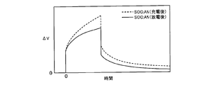
- FIG. 2A shows a voltage behavior when discharging (here, pulse discharging) is performed using the secondary battery 1 when the SOC (State of Charge) is A (A> 0) [%].
- FIG. 2B shows voltage behavior when charging (here, pulse charging) is performed using the secondary battery 1 when the SOC is A (A> 0) [%].
- the vertical axis indicates the amount of voltage change associated with discharge or charge
- the horizontal axis indicates time.
- the SOC is the ratio of the current charge capacity to the full charge capacity.
- the dotted line shows the case where the SOC of the secondary battery 1 is set to A [%] by charging the secondary battery 1
- the solid line shows the case where the secondary battery 1 is discharged.
- 6 shows the case where the SOC of the secondary battery 1 is set to A [%].
- FIG. 2C is a schematic view showing a change in the internal state of the positive electrode active material when the secondary battery 1 is charged.
- the charging of the secondary battery 1 changes the SOC of the secondary battery 1 from 0 [%] to A [%].
- the positive electrode active material is regarded as a sphere.
- FIG. 2D is a schematic view showing a change in the internal state of the positive electrode active material when the secondary battery 1 is discharged.
- the SOC of the secondary battery 1 is changed from 100% to A% by the discharge of the secondary battery 1.
- hatched regions indicate regions where lithium is present in the positive electrode active material.
- the non-hatched areas indicate areas where lithium is not present.
- the voltage behavior changes in accordance with the charge / discharge history until the SOC is set to A [%]. That is, as described above, the performance of the secondary battery 1 changes in accordance with the charge and discharge history.
- the voltage change amount (absolute value) ⁇ V of the secondary battery 1 whose SOC is set to A [%] by the discharge corresponds to the SOC A by charging.
- the voltage change amount (absolute value) ⁇ V of the secondary battery 1 set to [%] is larger.
- the voltage change amount ⁇ V has a negative value.
- the resistance value of the secondary battery 1 whose SOC is set to A [%] is set to the SOC [A] by charging. It can be seen that the resistance value of the secondary battery 1 is higher.
- the voltage change amount ⁇ V of the secondary battery 1 whose SOC is set to A [%] by charging is set to 2 times when the SOC is set to A [%].
- the voltage change amount ⁇ V of the secondary battery 1 becomes larger.
- the voltage change amount ⁇ V has a positive value.
- the resistance value of the secondary battery 1 whose SOC is set to A [%] is set to the SOC [A] by discharging. It can be seen that the resistance value of the secondary battery 1 is higher.
- the resistance value of the secondary battery 1 is affected by the charge and discharge history up to the present. Specifically, the resistance value of the secondary battery 1 when the past and current energized states are in the discharged state is secondary when the past energized state is in the charged state and the current energized state is in the discharged state. It becomes higher than the resistance value of the battery 1. Further, the resistance value of the secondary battery 1 when the past and current energized states are in the charge state is the secondary battery 1 when the past energized state is in the discharged state and the current energized state is in the charged state. It becomes higher than the resistance value.
- the resistance value of the secondary battery 1 when the past and current energization states (charging state or discharging state) are the same is based on the resistance value of the secondary battery 1 when the past and current energization states are different from each other. Will also be high.
- the resistance (internal resistance) of the secondary battery 1 includes a direct current resistance, a reaction resistance, and a diffusion resistance.
- the direct current resistance is a purely electrical resistance to the movement of electrons.
- the reaction resistance is a resistance (charge transfer resistance) that acts equivalently as an electric resistance when a reaction current is generated on the surface of the active material.
- the diffusion resistance is a resistance when lithium diffuses inside the active material.
- the voltage fluctuation caused by the diffusion resistance occurs at a later timing than the voltage fluctuation caused by the DC resistance or the reaction resistance.
- the voltage value of the secondary battery 1 changes, but this voltage fluctuation is caused by DC resistance or reaction resistance.
- FIG. 2A or 2B immediately after performing pulse discharge or pulse charge, the behavior of the voltage change amount ⁇ V indicated by the dotted line and the behavior of the voltage change amount ⁇ V indicated by the solid line coincide with each other. .
- the influence of the above-mentioned diffusion resistance is taken into consideration. Specifically, as described below, the diffusion coefficient used in the battery model is corrected based on the charge / discharge history of the secondary battery 1.
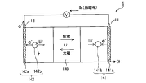
- FIG. 3 is a schematic view showing the configuration of the secondary battery 1.
- the coordinate axis x shown in FIG. 3 indicates the position in the thickness direction of the electrode.
- the secondary battery 1 has a positive electrode 141, a negative electrode 142, and a separator 143.
- the separator 143 is located between the positive electrode 141 and the negative electrode 142, and contains an electrolytic solution.
- the positive electrode 141 has a current collecting plate 141 a made of aluminum or the like, and the current collecting plate 141 a is electrically connected to the positive electrode terminal 11 of the secondary battery 1.
- the negative electrode 142 has a current collecting plate 142 a made of copper or the like, and the current collecting plate 142 a is electrically connected to the negative electrode terminal 12 of the secondary battery 1.
- Each of the negative electrode 142 and the positive electrode 141 is configured of an aggregate of spherical active materials 142 b and 141 b.
- a chemical reaction is performed on the interface of the active material 142 b of the negative electrode 142 to release lithium ions Li + and electrons e ⁇ .
- a chemical reaction is performed to absorb lithium ions Li + and electrons e ⁇ .
- FIG. 3 shows the state when the secondary battery 1 is discharged.
- the basic battery model equation used in the present embodiment is expressed by a basic equation consisting of the following equations (1) to (11).
- FIG. 4 shows a list of variables and constants used in the battery model equation.
- subscript e indicates that it is a value in the electrolyte
- s indicates that it is a value in the active material.
- the subscript j distinguishes between the positive electrode and the negative electrode, and indicates the value at the positive electrode when j is 1 and indicates the value at the negative electrode when j is 2.
- the subscript j is omitted when the variables or constants in the positive electrode and the negative electrode are comprehensively described.
- the notation of (t) showing that it is a function of time the notation of (T) showing the dependency of battery temperature Tb, or the notation of ( ⁇ ) showing the dependency of local SOC ⁇ , etc. May be omitted.
- the symbol # attached to a variable or constant represents an average value.
- the following equation (3) holds as a formula relating to the lithium ion concentration conservation law in the electrolytic solution.
- the diffusion equation of the following equation (4) and the boundary condition equation shown in the following equations (5) and (6) are applied as equations relating to the lithium concentration conservation law in the active material.
- the following formula (5) shows the boundary conditions in the central part of the active material
- the following formula (6) shows the boundary conditions in the interface of the active material (hereinafter, also simply referred to as “interface”).
- the local lithium concentration distribution (concentration distribution) at the interface of the active material is defined as the local SOC.
- ⁇ j representing the local SOC is defined by the following equation (7).
- c sej in the following formula (7) indicates the lithium concentration at the active material interface of the positive electrode and the negative electrode.
- c sj, max indicates the limit lithium concentration in the active material.
- the battery model equations represented by the basic equations of the above equations (1) to (11) can be simplified as described below. By simplifying the battery model formula, it is possible to reduce the operation load and shorten the operation time.
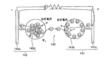
- the battery model shown in FIG. 5 it is possible to model an electrode reaction on the surface of the active material model 141 b of the positive electrode 141 or to model an electrode reaction on the surface of the active material model 142 b of the negative electrode 142. Further, in the battery model shown in FIG. 5, it is possible to model the diffusion (diameter direction) of lithium inside the active material models 141 b and 142 b and the diffusion (concentration distribution) of lithium ions in the electrolytic solution. Furthermore, in each part of the battery model shown in FIG. 5, the potential distribution and the temperature distribution can be modeled.
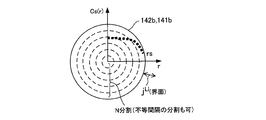
- the lithium concentration c s inside each of the active material models 141 b and 142 b can be expressed as a function on the coordinate r in the radial direction of the active material models 141 b and 142 b.
- r is the distance from the centers of the active material models 141 b and 142 b to each point
- r s is the radius of the active material models 141 b and 142 b.
- the active material models 141 b and 142 b shown in FIG. 6 are used to estimate the lithium diffusion phenomenon inside the active material accompanying the electrochemical reaction at the interface.
- N natural number of 2 or more
- the equation (10) relating to the charge conservation law in the active material can also be simplified to the following equation (17). That is, the potential ⁇ sj of the active material is also approximated as a quadratic function of x.
- the average potential ⁇ sj # in the active material used to calculate the overvoltage ⁇ ⁇ ⁇ j # is determined by the following expression (18) obtained by integrating the following expression (17) by the electrode thickness L j . Therefore, regarding the positive electrode 141, the potential difference between the active material average potential ⁇ s1 # and the active material potential at the boundary between the active material model 141b and the current collector plate 141a is represented by the following formula (19). Similarly, for the negative electrode 142, the following equation (20) is established.
- FIG. 7 shows the relationship between the terminal voltage V (t) of the secondary battery 1 and the average potentials obtained as described above.
- the voltage drop at the separator 143 is proportional to the current density I (t), and L s / ⁇ s eff II (t) Become.
- Average potentials ⁇ s1 and ⁇ s2 are determined using FIG. 7, and the determined values are substituted into the above equation (22). Further, the average overvoltage ⁇ 1 # (t) and ⁇ 2 # (t) obtained from the above equation (25) are substituted into the above equation (23). As a result, a voltage-current relationship model formula (M1a) according to the electrochemical reaction model formula is derived based on the formulas (1 ′), (21) and the formula (2 ′).
- the active material diffusion model equation (M2a) for the active material models 141b and 142b is determined by the above equation (4 ′) and boundary condition equations (5 ′) and (6 ′), which are lithium concentration conservation rules (diffusion equation) .
- the first term on the right side of the model formula (M1a) represents the open circuit voltage (OCV) determined by the concentration of the reactant (lithium) on the surface of the active material
- OCV open circuit voltage
- the second term on the right side represents the overvoltage ( ⁇ 1 # - ⁇ 2
- the third term on the right side indicates the voltage drop due to the current flowing to the secondary battery. That is, the direct current resistance of the secondary battery 10 is represented by Rd (T) in the formula (M2a).
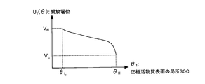
- Open-circuit potential U 1 included in the formula (M1a) will depend on the local SOC [theta] 1 of the positive electrode active material model 141b. Thus, if the correspondence between the open-circuit potential U 1 and local SOC [theta] 1 is previously obtained by experiments or the like, by specifying the local SOC [theta] 1, it is possible to calculate the open-circuit potential U 1. Correspondence between the open-circuit potential U 1 and local SOC [theta] 1 can be expressed as a map or a function, information about the correspondence relationship may be stored in memory 300a.
- Figure 8 shows the map the correspondence between open-circuit potential U 1 and local SOC [theta] 1. According to the map shown in FIG. 8, in response to an increase in local SOC [theta] 1, open-circuit potential U 1 is lowered.
- the local SOC ⁇ H is higher than the local SOC ⁇ L
- the open potential V H is higher than the open potential V L.
- open-circuit potential U 2 is dependent on the local SOC [theta] 2 of the negative electrode active material model 142b.
- the correspondence between the open-circuit potential U 2 and the local SOC [theta] 2 is previously obtained by experiments or the like, by identifying the local SOC [theta] 2, can be calculated open-circuit potential U 2.
- Correspondence between the open-circuit potential U 2 and the local SOC [theta] 2 can be represented as a map or a function, information about the correspondence relationship may be stored in memory 300a.
- FIG 9 depicts the map the correspondence between open-circuit potential U 2 and the local SOC [theta] 2. According to the map shown in FIG. 9, in response to an increase in local SOC [theta] 2, open-circuit potential U 2 is increased.
- the exchange current density i 01 , i 02 included in the equation (M1a) depends on the local SOC ⁇ 1 , ⁇ 2 and the battery temperature Tb. Therefore, if correspondence relationships (maps or functions) of exchange current density i 01 , i 02 , local SOC ⁇ 1 , ⁇ 2 and battery temperature Tb are prepared in advance, exchange from local SOC ⁇ 1 , ⁇ 2 and battery temperature Tb The current density i 01 , i 02 can be identified.
- the direct current resistance Rd depends on the battery temperature Tb. Therefore, if the correspondence (map or function) of the direct current resistance Rd and the battery temperature Tb is prepared in advance, the direct current resistance Rd can be specified from the battery temperature Tb. In addition, about the correspondence of direct current resistance Rd and battery temperature Tb, it can create based on experimental results, such as the known alternating current impedance measurement regarding the secondary battery 1. FIG.
- the battery model shown in FIG. 5 can be further simplified. Specifically, a common active material model can be used as the active material of the electrodes 142 and 141. By treating the active material models 141 b and 142 b shown in FIG. 5 as one active material model, it is possible to replace the equation as shown in the following equation (26). In the following formula (26), the subscript j indicating the distinction between the positive electrode 141 and the negative electrode 142 is omitted.
- the model formulas (M1a) and (M2a) can be represented by the following formulas (M1b) and (M2b). Also, in a battery model using one active material model, the following equation (21 ′) is applied instead of the above equation (21) as a relational expression of the current density I (t) and the reaction current density j j Li Ru.
- Equation (M1c) is obtained by first approximation (linear approximation) of the arcsinh term in the above equation (M1a). By performing linear approximation in this manner, calculation load can be reduced and calculation time can be shortened.
- the second term on the right side is also represented by the product of the current density I (t) and the reaction resistance Rr.
- the reaction resistance Rr is calculated from the exchange current densities i 01 and i 02 depending on the local SOC ⁇ 1 and ⁇ 2 and the battery temperature Tb, as shown in the above equation (27). Therefore, when the above equation (M1c) is used, the correspondence (map or function) of the local SOC ⁇ 1 , ⁇ 2 , the battery temperature Tb and the exchange current density i 01 , i 02 may be prepared in advance.
- the above equation (28) is obtained according to the above equation (M1c) and the above equation (27).
- Equation (M1e) is represented by the following equation (M1f) by performing linear approximation (linear approximation).
- FIG. 10 is a schematic diagram showing an internal configuration of the controller 300.
- the battery state estimation unit 310 included in the controller 300 includes a diffusion estimation unit 311, an open circuit voltage estimation unit 312, a current estimation unit 313, a parameter setting unit 314, and a boundary condition setting unit 315.
- battery state estimating unit 310 calculates current density I (t) by using equation (M1f) and equation (M2b).
- the current density I (t) is calculated using the above formulas (M1f) and (M2b), but the present invention is not limited to this. Specifically, the current density I (t) is calculated based on any combination of the above formula (M1a) to the above formula (M1e) and the above formula (M2a) or the above formula (M2b). Can.
- the diffusion estimating unit 311 calculates the lithium concentration distribution inside the active material based on the boundary condition set by the boundary condition setting unit 315 using the above-mentioned equation (M2b).
- the boundary conditions are set based on the above equation (5 ′) or the above equation (6 ′).
- the diffusion estimation unit 311 calculates the local SOC ⁇ based on the calculated lithium concentration distribution, using the above equation (7).
- Diffusion estimation section 311 outputs information on the local SOC ⁇ to open circuit voltage estimation section 312.
- ⁇ 1 and ⁇ 2 are calculated as the local SOC ⁇ .
- the local SOC ⁇ in one active material model is calculated.
- the open circuit voltage estimation unit 312 specifies the open potentials U 1 and U 2 of the electrodes 142 and 141 based on the local SOC ⁇ ( ⁇ 1 , ⁇ 2 ) calculated by the diffusion estimation unit 311. Specifically, the open circuit voltage estimation unit 312 can specify the open potentials U 1 and U 2 by using, for example, the maps shown in FIGS. 8 and 9. The open circuit voltage estimation unit 312 can calculate the open circuit voltage of the secondary battery 1 based on the open potentials U 1 and U 2 . Open circuit voltage of the secondary battery 1 is obtained by subtracting the open-circuit potential U 2 from the open potential U 1.
- the parameter setting unit 314 sets parameters used in the battery model according to the battery temperature Tb and the local SOC ⁇ .
- the battery temperature Tb a temperature detected by the temperature sensor 203 is used.
- the local SOC ⁇ is obtained from the diffusion estimation unit 311.
- the parameters set by the parameter setting unit 314 include the diffusion constant D s in the above equation (M2b), the current density i 0 in the above equation (M1f), and the direct current resistance Rd.
- the current estimation unit 313 calculates (estimates) the current density I (t) using the following equation (M3a).
- the following formula (M3a) is a formula obtained by modifying the above formula (M1f).
- the open circuit voltage U ( ⁇ , t) is the open circuit voltage U ( ⁇ ) estimated by the open circuit voltage estimation unit 312.
- the voltage V (t) is the battery voltage Vb acquired using the monitoring unit 201.
- Rd (t) and i 0 ( ⁇ , T, t) are values set by the parameter setting unit 314.
- the current density I (t) can be calculated by the same method as the above-mentioned formula (M3a). .
- the boundary condition setting unit 315 determines the reaction current density (lithium production amount) j j Li from the current density I (t) calculated by the current estimation unit 313 using the above equation (21) or the above equation (21 ′). calculate. Then, the boundary condition setting unit 315 updates the boundary condition in the equation (M2b) using the equation (6 ′).
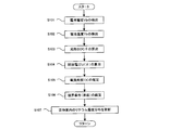
- step S101 battery state estimation unit 310 detects voltage value (battery voltage) Vb of secondary battery 1 based on the output of monitoring unit 201.
- step S102 battery state estimation unit 310 detects temperature (battery temperature) Tb of secondary battery 1 based on the output of temperature sensor 203.
- step S103 the battery state estimation unit 310 (diffusion estimation unit 311) calculates the local SOC ⁇ based on the lithium concentration distribution at the time of the previous calculation using the above equation (M2b).
- step S104 the battery state estimation unit 310 (open circuit voltage estimation unit 312) calculates an open circuit voltage U ( ⁇ ) from the local SOC ⁇ obtained in step S103.
- step S105 the battery state estimation unit 310 (current estimation unit 313) calculates (estimates) the current density I (t) using the above equation (M3a).
- the estimated current density I (t) is obtained by the above equation (B), the battery voltage Vb, the battery temperature Tb, the open circuit voltage U (.theta.) Obtained in step S103, and the parameter value set by the parameter setting unit 314. It is obtained by substituting for M3a).
- step S106 the battery state estimation unit 310 (boundary condition setting unit 315) calculates a reaction current density (lithium production amount) j j Li from the estimated current density I (t) obtained in step S105.
- the battery state estimation unit 310 (boundary condition setting unit 315) sets the boundary condition at the active material interface of the above formula (M2b) using the calculated reaction current density.
- step S107 the battery state estimation unit 310 (diffusion estimation unit 311) calculates the lithium concentration distribution inside the active material model using the above equation (M2b), and updates the estimated value of the lithium concentration in each region .
- the lithium concentration (updated value) in the outermost divided region is used for the process of step S103 (calculation of the local SOC ⁇ ) when the process shown in FIG. 11 is performed next time.
- the battery current (battery current density I (t)) is estimated with the battery voltage Vb as an input, and based on this, the internal state of the secondary battery 1 (lithium concentration distribution in active material) ) Can be estimated.
- the SOC of the secondary battery 1 can be estimated.
- the process of estimating the SOC is performed by the controller 300.
- the controller 300 calculates the lithium average concentration c save based on the lithium concentration distribution by using the following equation (29).
- controller 300 estimates the SOC of secondary battery 1 based on the following formula (30).
- FIG. 12 shows the relationship between the lithium average concentration c save and the SOC (estimated value) of the positive electrode active material model 141 b.
- FIG. 12 shows the relationship between the average lithium concentration c save and the SOC of the positive electrode active material model 141 b, the present invention is not limited to this. That is, instead of average lithium concentration c save in the positive electrode active material model 141b, it is also possible to use a lithium average concentration c save in the negative electrode active material model 142b.
- the SOC (estimated value) decreases in response to the increase of the lithium average concentration c save .
- the diagram is obtained. Linear interpolation can be performed as shown in FIG. Thereby, the SOC of the secondary battery 1 can be calculated from the lithium average concentration c save by using the above equation (30).
- the diffusion coefficient D s used in the diffusion equation shown in the above equation (M2a) or (M2b) is corrected. Specifically, the diffusion coefficient D s is corrected based on the following equation (31).
- the diffusion coefficient D s corrected based on the following equation (31) is used .
- D s — ini is a reference value of the diffusion coefficient, and is a value specified in advance by experiment or the like in a state where the influence of the charge and discharge history can be ignored.
- the diffusion coefficient D s_ini depends on the battery temperature Tb. Therefore, if the correspondence (map or function) of the diffusion coefficient D s_ini and the battery temperature Tb is obtained in advance, the diffusion coefficient D s_ini can be calculated by detecting the battery temperature Tb.
- information on the correspondence between the diffusion coefficient D s — ini and the battery temperature Tb can be stored in the memory 300 a.
- FIG. 13 shows the correspondence between the diffusion coefficient D s_ini and the battery temperature Tb.
- the diffusion coefficient D s_ini rises.
- the diffusion coefficient D s_ini decreases.
- diffusion coefficient D s_ini not only the dependence of the battery temperature Tb but also the dependence of the local SOC ⁇ can be considered.
- diffusion coefficient D s_ini is calculated by specifying battery temperature Tb and local SOC ⁇ . be able to.
- information on the correspondence between the diffusion coefficient D s — ini , the battery temperature Tb, and the local SOC ⁇ can be stored in the memory 300 a.
- the diffusion coefficient D s_ini corresponding to each of the diffusion coefficients D s1 and D s2 may be calculated.
- the method of calculating the diffusion coefficient D s_ini is as described above.
- the correction coefficient k shown in the said Formula (31) is a correction coefficient.
- the correction coefficient k is used to correct the diffusion coefficient D s_ini in consideration of the influence of the charge and discharge history of the secondary battery 1.
- parameters for specifying the charge and discharge history for example, there are a change amount ⁇ SOC and an average current value I_ave.
- the amount of change ⁇ SOC is an amount (maximum value) in which the SOC of the secondary battery 1 has changed during the predetermined period ⁇ t. Specifically, if the maximum value and the minimum value of SOC are specified from the variation history of SOC during the predetermined period ⁇ t, the difference between the SOC (maximum value) and the SOC (minimum value) becomes the amount of change ⁇ SOC.
- the change amount ⁇ SOC can be used as the charge / discharge history.
- the amount of change ⁇ SOC increases, the lithium concentration distribution inside the active material is more likely to change.
- the average current value I_ave is an average value of current values Ib when the secondary battery 1 is charged and discharged during a predetermined period ⁇ t. If current value Ib is detected by current sensor 202 during predetermined period ⁇ t, average current value I_ave can be calculated. When the secondary battery 1 is charged or discharged, the current value Ib changes between a positive value and a negative value, so the current value Ib of the secondary battery 1 can be used as the charge and discharge history.
- the current value Ib is likely to change, so it is preferable to use the average current value I_ave as the charge and discharge history during the predetermined period ⁇ t. If the integrated value of the discharge current is larger than the integrated value of the charging current during the predetermined period ⁇ t, the average current value I_ave becomes a positive value. On the other hand, if the integrated value of the charge current is larger than the integrated value of the discharge current, the average current value I_ave becomes a negative value.
- the correction coefficient k is changed according to the parameter specifying the charge and discharge history. Specifically, if the correspondence (map or function) between at least one of the variation ⁇ SOC and the average current value I_ave and the correction coefficient k is determined in advance by experiment or the like, the variation ⁇ SOC and the average current value I_ave are specified. By doing this, the correction coefficient k can be calculated.
- information on the correspondence relationship between the change amount ⁇ SOC (or / and the average current value I_ave) and the correction coefficient k can be stored in the memory 300 a.
- the correspondence relationship between the change amount ⁇ SOC (or / and the average current value I_ave) and the correction coefficient k may differ depending on the material (in particular, the material of the active material) constituting the secondary battery 1 and the like. For this reason, it is necessary to obtain the above-mentioned correspondence by experiments using the secondary battery 1 actually used. For example, depending on the material constituting the secondary battery 1, the correction coefficient k can be increased as the change amount ⁇ SOC increases, or the correction coefficient k can be increased as the average current value I_ave increases.
- the influence of the change amount ⁇ SOC on the correction coefficient k and the influence of the average current value I_ave on the correction coefficient k may be different from each other is there.
- the correction coefficient k can be calculated in consideration of the respective effects.
- the correction coefficient k1 is calculated only from the change amount ⁇ SOC
- the correction coefficient k2 is calculated only from the average current value I_ave.
- the correction coefficient k can be calculated by weighting the correction coefficients k1 and k2 and adding them. If the influence of the change amount ⁇ SOC on the correction coefficient k and the influence of the average current value I_ave on the correction coefficient k are confirmed by experiments etc., it is possible to set a weighting coefficient to be multiplied by each of the correction coefficients k1 and k2. it can.
- the diffusion coefficient D s is calculated by multiplying the diffusion coefficient D s_ini by the correction coefficient k, but the present invention is not limited to this.
- the diffusion coefficient D s can also be calculated by adding or subtracting a correction value to or from the diffusion coefficient D s_ini .
- the correction value may be changed according to the change amount ⁇ SOC or the average current value I_ave.
- the method of correcting the diffusion coefficient D s_ini can be selected as appropriate.
- the predetermined period ⁇ t described above is a period up to the present, and is a period of charge and discharge history that affects the current performance of the secondary battery 1.
- the predetermined period ⁇ t can be set by an experiment or the like while considering whether the current performance of the secondary battery 1 is affected.
- the predetermined period ⁇ t may differ depending on the material constituting the secondary battery 1.
- the predetermined period ⁇ t is a period up to the present, data (SOC or current value Ib) past the predetermined period ⁇ t with respect to the current may be erased from the memory 300a. That is, whenever the SOC and the current value Ib are newly obtained, the oldest data (SOC and the current value Ib) stored in the memory 300a may be erased. Thus, past data for a predetermined period ⁇ t can be continuously stored in the memory 300 a based on the current.
- charging and discharging are performed in various patterns. For example, when the vehicle is driven using only the output of the secondary battery 1, the discharge of the secondary battery 1 is continuously performed. In addition, when performing external charging, charging of the secondary battery 1 is continuously performed.
- the vehicle in the vehicle provided with the secondary battery 1 and the engine, the vehicle can be run while using the secondary battery 1 and the engine in combination.
- charging / discharging of the secondary battery 1 is controlled such that the SOC of the secondary battery 1 changes along the reference SOC.
- the reference SOC can be set in advance.
- the secondary battery 1 When the SOC of the secondary battery 1 becomes higher than the reference SOC, the secondary battery 1 is actively discharged, whereby the SOC of the secondary battery 1 approaches the reference SOC. Further, when the SOC of the secondary battery 1 becomes lower than the reference SOC, the secondary battery 1 is positively charged, whereby the SOC of the secondary battery 1 approaches the reference SOC.
- the secondary battery 1 when the secondary battery 1 is charged, the secondary battery 1 can be charged using regenerative electric power. Also, when the generator converts kinetic energy from the engine into electrical energy, the power generated by the generator can be used to charge the secondary battery 1.
- the SOC of the secondary battery 1 can be changed along the reference SOC.
- charge and discharge of the secondary battery 1 are alternately repeated.
- the diffusion coefficient D s can be set in advance in consideration of the charging and discharging pattern.
- the diffusion coefficient D s is corrected in consideration of the actual charge and discharge history, the change in battery performance accompanying the charge and discharge history is reflected in estimating the internal state of the secondary battery 1 It can be done. That is, the diffusion coefficient D s after correction easily matches the diffusion coefficient D s corresponding to the actual internal state of the secondary battery 1, and the internal state of the secondary battery 1 can be estimated with high accuracy.
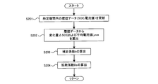
- step S201 the controller 300 updates history data (SOC and current value Ib) during a predetermined period ⁇ t each time the controller 300 acquires the SOC of the secondary battery 1 and the current value Ib. Specifically, the controller 300 stores the newly acquired SOC and current value Ib in the memory 300a, and erases, from the memory 300a, the history data (SOC and current value Ib) acquired most recently.
- step S202 the controller 300 calculates the amount of change ⁇ SOC and the average current value I_ave using the history data stored in the memory 300a.
- step S203 controller 300 calculates correction coefficient k corresponding to change amount ⁇ SOC calculated in the process of step S202 and average current value I_ave using the correspondence relationship between change amount ⁇ SOC, average current value I_ave and correction coefficient k. Do.
- step S204 the controller 300 calculates the diffusion coefficient D s using the above equation (31).
- the correction coefficient k the correction coefficient k calculated in the process of step S203 is used. Further, by detecting the battery temperature Tb and calculating the SOC of the secondary battery 1, it is possible to calculate the diffusion coefficient (reference value) D s_ini .
- the processing shown in FIG. 11 is performed using the latest diffusion coefficient D s .
- the internal state of the secondary battery 1 can be accurately estimated. If the internal state of the secondary battery 1 can be accurately estimated, the SOC of the secondary battery 1 can also be accurately estimated.
- a battery system that is Embodiment 2 of the present invention will be described.
- the same reference numerals are used for the same members as the members described in the first embodiment, and the detailed description will be omitted.
- differences from the first embodiment will be mainly described.
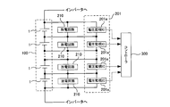
- the monitoring unit 201 has voltage monitoring ICs (Integrated Circuits) 201a as many as the number of secondary batteries 1 constituting the battery assembly 100, and each voltage monitoring IC 201a is a secondary battery. Connected in parallel to 1.
- the voltage monitoring IC 201 a detects the voltage value Vb of the secondary battery 1, and outputs the detection result to the controller 300.
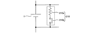
- a discharge circuit 210 is connected in parallel to each secondary battery 1, and the discharge circuit 210 suppresses variations in voltage value (OCV) or SOC (State of Charge) in the plurality of secondary batteries 1. Used for The operation of the discharge circuit 210 is controlled by the controller 300.
- the controller 300 determines that the voltage value (or SOC) of a specific secondary battery 1 is higher than the voltage value (or SOC) of another secondary battery 1 based on the output of the voltage monitoring IC 201a.
- Only the discharge circuit 210 corresponding to the specific secondary battery 1 is operated.
- the specific secondary battery 1 can be discharged, and the voltage value of the specific secondary battery 1 can be made equal to the voltage value of the other secondary batteries 1.
- the process of equalizing voltage values (or SOCs) in the plurality of secondary batteries 1 constituting the battery assembly 100 using the discharge circuit 210 is referred to as equalization process.
- the number of secondary batteries 1 to be discharged may be one or more.
- FIG. 16 shows a configuration of secondary battery 1 and discharge circuit 210.
- the discharge circuit 210 includes a resistive element 210a and a switch element 210b. In response to the control signal from controller 300, switch element 210b switches between on and off. When the switch element 210b is switched from off to on, a current flows from the secondary battery 1 to the resistor element 210a, and the secondary battery 1 can be discharged.
- the equalization process can be performed when the ignition switch is off. After the equalization process is performed while the ignition switch is off, when the ignition switch is switched on, a discharge history is generated in the secondary battery 1 that is the target of the equalization process. Therefore, for the secondary battery 1 that has become the target of the equalization process, it is necessary to consider the discharge history accompanying the equalization process when calculating the diffusion coefficient D s .
- the diffusion coefficient D s is calculated in consideration of the discharge history associated with the equalization process for the secondary battery 1 that is the target of the equalization process.
- the secondary battery 1 which has not become the target of the equalization process since the discharge accompanying the equalization process is not performed, it is not necessary to consider the discharge history.
- the diffusion coefficient D s when the ignition switch is turned on may be calculated. it can.
- the voltage value OCV_s after the equalization processing is lower than the voltage value OCV_e before the equalization processing. For this reason, it is possible to calculate the change amount ⁇ OCV of the voltage value OCV accompanying the equalization process.
- the amount of change ⁇ OCV is calculated based on the following equation (32).
- change amount ⁇ OCV corresponds to SOC change amount ⁇ SOC. Therefore, if the correspondence (map or function) of the variation ⁇ OCV and the correction coefficient k is obtained in advance as in the first embodiment, the correction coefficient k can be calculated by calculating the variation ⁇ OCV. . Information on the correspondence between the change amount ⁇ OCV and the correction coefficient k can be stored in the memory 300 a.
- the correction coefficient k can be calculated based on the change amount ⁇ OCV.
- the predetermined period ⁇ t is longer than the period during which the equalization process is performed, the charge / discharge history before the ignition switch is turned off may also be taken into consideration.
- the correction coefficient k may be calculated based on the change amount ⁇ SOC.
- the change amount ⁇ SOC is calculated, the change in SOC accompanying the equalization process is also taken into consideration. Specifically, when the SOC after performing the equalization process becomes the minimum value during the predetermined period ⁇ t, the change amount ⁇ SOC is calculated using this SOC.
- the current value at the time of equalization processing corresponds to the average current value I_ave described in the first embodiment. Therefore, as in the first embodiment, if the correspondence relationship (map or function) between change amount ⁇ OCV, current value at the time of equalization processing, and correction coefficient k is determined in advance by experiment, etc., change amount ⁇ OCV and The correction coefficient k can be calculated by specifying the current value at the time of equalization processing.
- information relating to the correspondence relationship between the variation amount ⁇ OCV, the current value at the time of equalization processing, and the correction coefficient k can be stored in the memory 300 a.
- the resistance value of resistance element 210 a of discharge circuit 210 is sufficiently larger than the resistance value (internal resistance) of secondary battery 1, at the time of equalization processing based on the resistance value of resistance element 210 a and change amount ⁇ OCV.
- the current value of can be calculated. Specifically, the current value at the time of equalization processing can be calculated based on the following equation (33).
- I is a current value (discharge current) at the time of equalization processing
- R res is a resistance value of the resistance element 210a.
- the resistance value of the circuit including the resistive element 210 a and the secondary battery 1 can be regarded as the resistance value R res of the resistive element 210 a.
- the correction coefficient k can be calculated based on the change amount ⁇ OCV and the current value I at the time of the equalization process.
- the predetermined period ⁇ t is longer than the period during which the equalization process is performed, the charge / discharge history before the ignition switch is turned off may also be taken into consideration.
- the correction coefficient k may be calculated based on the change amount ⁇ SOC and the average current value I_ave.
- the current value I at the time of equalization processing is also considered.
- the average current value I_ave is calculated based on the current value I at the time of equalization processing and the current value before the ignition switch is turned off.
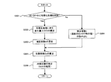
- processing for estimating the internal state of the secondary battery 1 will be described with reference to the flowchart shown in FIG.
- the process shown in FIG. 17 is started when the ignition switch is switched from off to on, and is executed by the controller 300. In the process shown in FIG. 17, only the period in which the equalization process is performed is set as the predetermined period ⁇ t.
- step S301 the controller 300 determines whether equalization processing has been performed on each secondary battery 1 while the ignition switch immediately before is off.
- the controller 300 can set a flag indicating execution of equalization processing when the equalization processing is performed while the ignition switch is off.
- the setting information of this flag can be stored in the memory 300a.
- the controller 300 can determine whether the equalization process has been performed by confirming the setting information of the flag.
- information on the secondary battery 1 that is the target of the equalization process is stored in the memory 300a.
- the information on the secondary battery 1 is information for specifying each of the plurality of secondary batteries 1 constituting the assembled battery 100. Specifically, for example, an identification number assigned to each secondary battery 1 can be used as the information related to the secondary battery 1.
- the controller 300 can specify the secondary battery 1 that is the target of the equalization process by using the information on the secondary battery 1.
- step S302 the controller 300 calculates the amount of change ⁇ OCV associated with the equalization process. As described above, the controller 300 calculates the change amount ⁇ OCV based on the voltage value OCV_s before the equalization process and the voltage value OCV_e after the equalization process. Information on the voltage values OCV_s and OCV_e can be stored in the memory 300a when the equalization process is performed.
- step S303 the controller 300 calculates the correction coefficient k based on the amount of change ⁇ OCV calculated in the process of step S302. Specifically, the controller 300 can calculate the correction coefficient k from the change amount ⁇ OCV by using the correspondence (map or function) of the change amount ⁇ OCV and the correction coefficient k.
- the correction coefficient k can be calculated in consideration of not only the change amount ⁇ OCV but also the current value at the time of equalization processing.
- the controller 300 reads out the correction coefficient k in step S304 for the secondary battery 1 that has not become the target of equalization processing.
- the correction coefficient k is a correction coefficient k calculated when the ignition switch is turned off, and is stored in the memory 300a.
- the controller 300 reads the correction coefficient k stored in the memory 300a. Thereby, the correction coefficient k regarding the secondary battery 1 which was not the object of equalization processing can be specified.
- step S305 the controller 300 calculates the diffusion coefficient D s using the correction coefficient k specified in the process of step S303 or step S304. Specifically, the controller 300 substitutes the correction coefficient k and the diffusion coefficient D s_ini calculated from the battery temperature Tb and the SOC of the secondary battery 1 into the equation (31) to obtain the diffusion coefficient D s . calculate.
- the diffusion coefficient D s is calculated using the correction coefficient k calculated in the process of step S303 for the secondary battery 1 that has become the target of the equalization process. Further, for the secondary battery 1 that has not become the target of equalization processing, the diffusion coefficient D s is calculated using the correction coefficient k read out in the processing of step S304.
- step S306 the controller 300 estimates the internal state of each secondary battery 1 based on the diffusion coefficient D s calculated in the process of step S305.
- the process of step S306 is the same as the process described in the first embodiment (FIG. 11).
- the diffusion coefficient D s at the time of estimating the internal state may be different between the secondary battery 1 targeted for equalization processing and the secondary battery 1 not targeted for equalization processing.
- the predetermined period ⁇ t includes the period before the ignition switch is turned off, as described above, the charge / discharge history before the ignition switch is turned off and the discharge history when the equalization process is performed
- the correction coefficient k may be calculated based on the above. Then, the diffusion coefficient D s can be calculated using the calculated correction coefficient k, and the internal state of the secondary battery 1 can be estimated.
- the diffusion coefficient D s of each secondary battery 1 can be specified in consideration of the equalization processing performed while the ignition switch is off.
- the internal state of the secondary battery 1 can be accurately estimated in consideration of the discharge history associated with the equalization process.
- the SOC of the secondary battery 1 can also be accurately estimated.
- a third embodiment of the present invention will be described.
- the same reference numerals are used for the same members as the members described in the first embodiment, and the detailed description will be omitted.
- the resistance value (particularly, the diffusion resistance) changes according to the charge and discharge history. For this reason, the resistance value of the secondary battery 1 can be corrected based on the following equation (34).
- R ini shown in the above equation (34) is a resistance value (reference value) specified in advance by an experiment or the like in a state where the influence of the charge and discharge history can be ignored. As the deterioration of the secondary battery 1 progresses with the passage of time, the resistance value R ini can be set in consideration of the usage period of the secondary battery 1.
- the use period is a period from when the secondary battery 1 is used for the first time to the present.
- the resistance value R ini can be calculated by specifying the use period.
- the use period can be measured, for example, using a timer. Further, information on the correspondence between the resistance value R ini and the use period can be stored in the memory 300 a.
- the resistance value R ini depends on the temperature Tb and the SOC of the secondary battery 1. Therefore, the correspondence (map or function) between at least one of battery temperature Tb and SOC and resistance value R ini can be obtained in advance by experiment or the like, and the information on the correspondence is stored in memory 300 a be able to. Here, by detecting the battery temperature Tb or estimating the SOC. The resistance value R ini can be calculated.
- the K 'shown in the said Formula (34) is a correction coefficient.
- the correction coefficient k ′ is used to correct the resistance value R ini in consideration of the influence of the charge and discharge history of the secondary battery 1.
- the correction coefficient k ′ is set in accordance with the parameter specifying the charge and discharge history. As this parameter, there are the change amount ⁇ SOC and the average current value I_ave described in the first embodiment.
- the correspondence relationship (map or function) between at least one of the change amount ⁇ SOC and the average current value I_ave and the correction coefficient k ′ is obtained in advance by experiment or the like, by specifying the change amount ⁇ SOC and the average current value I_ave, The correction coefficient k 'can be calculated.
- the method of calculating the change amount ⁇ SOC and the average current value I_ave is the same as the method described in the first embodiment.
- the process of calculating the resistance value R of the secondary battery 1 can be executed by the controller 300.
- the controller 300 calculates the resistance value R ini by acquiring at least one of the use period, the battery temperature Tb, and the SOC. Further, the controller 300 calculates the correction coefficient k ′ by acquiring history data (the amount of change ⁇ SOC or the average current value I_ave). If the resistance value R ini and the correction coefficient k ′ are calculated, the controller 300 can calculate the resistance value R based on the above equation (34).
- the influence of the charge and discharge history can be reflected in the resistance value R of the secondary battery 1.
- the resistance value R can be accurately estimated in the secondary battery 1 including the two-phase coexisting positive electrode active material.
Landscapes
- Engineering & Computer Science (AREA)
- Chemical & Material Sciences (AREA)
- Manufacturing & Machinery (AREA)
- Chemical Kinetics & Catalysis (AREA)
- Electrochemistry (AREA)
- General Chemical & Material Sciences (AREA)
- Power Engineering (AREA)
- Transportation (AREA)
- Life Sciences & Earth Sciences (AREA)
- Sustainable Development (AREA)
- Sustainable Energy (AREA)
- Mechanical Engineering (AREA)
- Materials Engineering (AREA)
- Microelectronics & Electronic Packaging (AREA)
- Secondary Cells (AREA)
- Charge And Discharge Circuits For Batteries Or The Like (AREA)
- Tests Of Electric Status Of Batteries (AREA)
- Battery Electrode And Active Subsutance (AREA)
Abstract
Description

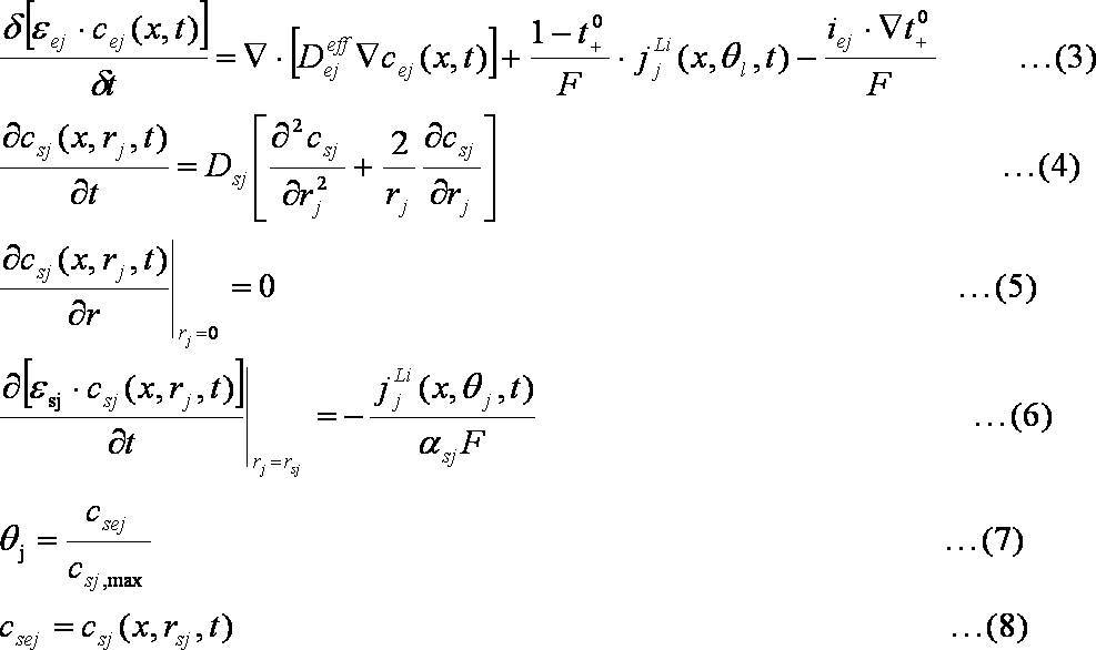

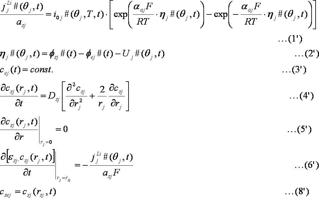
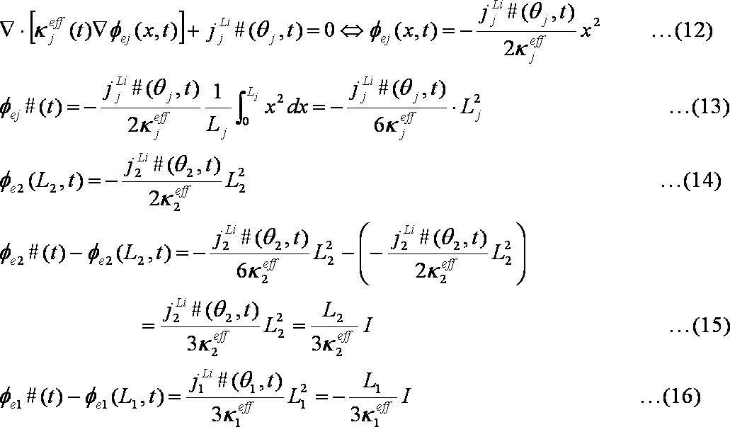
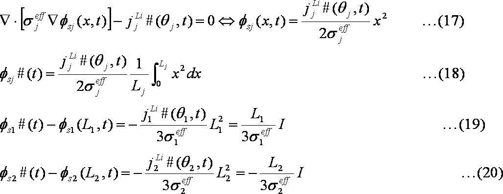



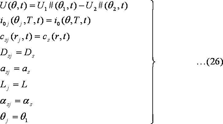
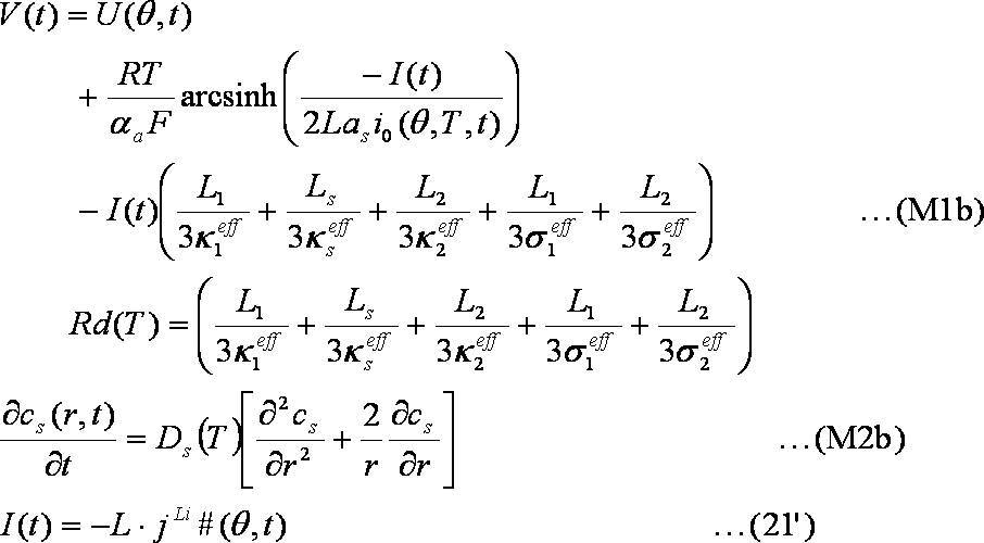
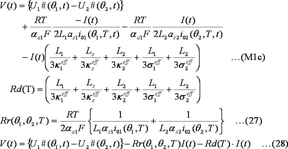










Claims (12)
- 二相共存型の正極活物質を用いたリチウムイオン二次電池と、
境界条件が設定された拡散方程式を用いて、前記リチウムイオン二次電池における活物質内のリチウム濃度分布を算出するコントローラと、を有し、
前記コントローラは、前記リチウムイオン二次電池の現在までの充放電状態を示す履歴データに応じて、前記拡散方程式で用いられる拡散係数を補正することを特徴とする電池システム。 - 前記コントローラは、拡散係数の基準値に、前記履歴データに応じた補正係数を乗算することにより、前記拡散方程式で用いられる拡散係数を算出することを特徴とする請求項1に記載の電池システム。
- 前記コントローラは、前記履歴データおよび前記補正係数の対応関係を用いて、現在の前記リチウムイオン二次電池における前記履歴データに対応した前記補正係数を算出することを特徴とする請求項2に記載の電池システム。
- 前記履歴データを記憶するメモリを有しており、
前記コントローラは、前記リチウムイオン二次電池の充電又は放電が行われるたびに、前記メモリに記憶された前記履歴データを更新することを特徴とする請求項1から3のいずれか1つに記載の電池システム。 - 前記履歴データは、現在までの所定期間内における前記リチウムイオン二次電池のSOCの変化量および、前記所定期間内における前記リチウムイオン二次電池の平均電流値のうち、少なくとも一方を含むことを特徴とする請求項1から4のいずれか1つに記載の電池システム。
- 前記変化量は、前記所定期間内における前記SOCの最大値および最小値の差であることを特徴とする請求項5に記載の電池システム。
- 前記リチウムイオン二次電池の温度を検出する温度センサを有しており、
前記コントローラは、前記リチウムイオン二次電池の温度および前記基準値の対応関係を用いて、前記温度センサの検出温度に対応する前記基準値を算出することを特徴とする請求項2に記載の電池システム。 - 前記コントローラは、前記リチウムイオン二次電池のSOCおよび前記基準値の対応関係を用いて、前記リチウムイオン二次電池の現在のSOCに対応する前記基準値を算出することを特徴とする請求項2に記載の電池システム。
- 複数の前記リチウムイオン二次電池が直列に接続されており、
前記各リチウムイオン二次電池と並列に接続され、前記各リチウムイオン二次電池を放電させる放電回路を有し、
前記履歴データは、前記放電回路によって前記リチウムイオン二次電池を放電したときの電圧変化量を含むことを特徴とする請求項1から8のいずれか1つに記載の電池システム。 - 前記コントローラは、
算出した前記リチウム濃度分布を用いて、前記活物質内におけるリチウムの平均濃度を算出し、
前記平均濃度および前記リチウムイオン二次電池のSOCの対応関係を用いて、算出した前記平均濃度に対応するSOCを算出することを特徴とする請求項1から9のいずれか1つに記載の電池システム。 - 前記リチウムイオン二次電池は、車両の走行に用いられる運動エネルギに変換される電力を出力することを特徴とする請求項1から10のいずれか1つに記載の電池システム。
- 二相共存型の正極活物質を用いたリチウムイオン二次電池と、
前記リチウムイオン二次電池の内部抵抗を推定するコントローラと、を有し、
前記コントローラは、前記リチウムイオン二次電池の現在までの充放電状態を示す履歴データに応じて、前記内部抵抗の基準値を補正することを特徴とする電池システム。
Priority Applications (5)
| Application Number | Priority Date | Filing Date | Title |
|---|---|---|---|
| DE112013006931.8T DE112013006931T5 (de) | 2013-04-11 | 2013-04-11 | Akkusystem |
| CN201380075508.1A CN105190985B (zh) | 2013-04-11 | 2013-04-11 | 电池系统 |
| US14/783,268 US10189366B2 (en) | 2013-04-11 | 2013-04-11 | Battery system |
| PCT/JP2013/002482 WO2014167602A1 (ja) | 2013-04-11 | 2013-04-11 | 電池システム |
| JP2015510952A JP5862836B2 (ja) | 2013-04-11 | 2013-04-11 | 電池システム |
Applications Claiming Priority (1)
| Application Number | Priority Date | Filing Date | Title |
|---|---|---|---|
| PCT/JP2013/002482 WO2014167602A1 (ja) | 2013-04-11 | 2013-04-11 | 電池システム |
Publications (1)
| Publication Number | Publication Date |
|---|---|
| WO2014167602A1 true WO2014167602A1 (ja) | 2014-10-16 |
Family
ID=51689040
Family Applications (1)
| Application Number | Title | Priority Date | Filing Date |
|---|---|---|---|
| PCT/JP2013/002482 Ceased WO2014167602A1 (ja) | 2013-04-11 | 2013-04-11 | 電池システム |
Country Status (5)
| Country | Link |
|---|---|
| US (1) | US10189366B2 (ja) |
| JP (1) | JP5862836B2 (ja) |
| CN (1) | CN105190985B (ja) |
| DE (1) | DE112013006931T5 (ja) |
| WO (1) | WO2014167602A1 (ja) |
Cited By (9)
| Publication number | Priority date | Publication date | Assignee | Title |
|---|---|---|---|---|
| JP2016167357A (ja) * | 2015-03-09 | 2016-09-15 | 株式会社デンソー | 2次電池制御装置 |
| JP2016201190A (ja) * | 2015-04-07 | 2016-12-01 | 株式会社デンソー | 充放電制御装置 |
| JP2017161490A (ja) * | 2015-09-18 | 2017-09-14 | 住友電気工業株式会社 | 内部抵抗算出装置、コンピュータプログラム及び内部抵抗算出方法 |
| EP3624252A1 (en) * | 2018-09-14 | 2020-03-18 | Toyota Jidosha Kabushiki Kaisha | Secondary battery system and method of estimating an internal state of secondary battery |
| CN111007410A (zh) * | 2018-10-08 | 2020-04-14 | 现代自动车株式会社 | 车辆电池诊断方法和装置 |
| KR20210095988A (ko) * | 2020-01-27 | 2021-08-04 | 도요타지도샤가부시키가이샤 | 이차 전지의 진단 장치, 및 soc 불균일 검지 방법 |
| JP2022532120A (ja) * | 2019-12-11 | 2022-07-13 | エルジー エナジー ソリューション リミテッド | 電極の相対的退化度を用いた二次電池の動作制御装置及び方法 |
| JP2024044899A (ja) * | 2022-09-21 | 2024-04-02 | トヨタ自動車株式会社 | 全固体電池のイオン分布状態推定装置 |
| JP2025062860A (ja) * | 2023-10-03 | 2025-04-15 | トヨタ自動車株式会社 | 電源システム |
Families Citing this family (19)
| Publication number | Priority date | Publication date | Assignee | Title |
|---|---|---|---|---|
| JP2015191878A (ja) * | 2014-03-31 | 2015-11-02 | 株式会社日立製作所 | リチウムイオン二次電池システムおよびリチウムイオン二次電池の状態診断方法 |
| DE102015117171B4 (de) * | 2014-10-09 | 2019-03-21 | Denso Corporation | Batteriezustandsabschätzvorrichtung |
| US9983266B2 (en) * | 2015-03-30 | 2018-05-29 | Eaton Intelligent Power Limited | Apparatus and methods for battery monitoring using discharge pulse measurements |
| US10137797B2 (en) * | 2015-09-28 | 2018-11-27 | Ford Global Technologies, Llc | Battery state of charge estimation based on current pulse duration |
| US9834112B2 (en) * | 2016-03-09 | 2017-12-05 | Ford Global Technologies, Llc | Battery state of charge estimation based on reduced order electrochemical models |
| US10040366B2 (en) | 2016-03-10 | 2018-08-07 | Ford Global Technologies, Llc | Battery terminal voltage prediction |
| US10023064B2 (en) | 2016-03-10 | 2018-07-17 | Ford Global Technologies, Llc | Power capability estimation for vehicle battery systems |
| JP6647111B2 (ja) | 2016-03-29 | 2020-02-14 | 古河電気工業株式会社 | 二次電池劣化推定装置および二次電池劣化推定方法 |
| JP6339618B2 (ja) | 2016-03-29 | 2018-06-06 | 古河電気工業株式会社 | 二次電池劣化推定装置および二次電池劣化推定方法 |
| JP2017204407A (ja) | 2016-05-12 | 2017-11-16 | トヨタ自動車株式会社 | 燃料電池システム及びその制御方法 |
| US11462929B2 (en) * | 2016-10-04 | 2022-10-04 | University Of Washington | Systems and methods for direct estimation of battery parameters using only charge/discharge curves |
| US10566811B2 (en) * | 2017-01-11 | 2020-02-18 | Samsung Electronics Co., Ltd. | Method and apparatus estimating and controlling battery state |
| CN107571747B (zh) * | 2017-07-07 | 2020-06-16 | 北汽福田汽车股份有限公司 | Soc的平滑控制方法、装置、电池管理系统及车辆 |
| KR102608468B1 (ko) | 2017-11-28 | 2023-12-01 | 삼성전자주식회사 | 배터리 상태 추정 방법 및 장치 |
| JP6947014B2 (ja) * | 2017-12-25 | 2021-10-13 | トヨタ自動車株式会社 | 二次電池システムおよび二次電池の制御方法 |
| KR102655792B1 (ko) | 2018-10-19 | 2024-04-09 | 삼성전자주식회사 | 배터리 충전 장치 및 방법 |
| CN110861534B (zh) * | 2019-11-27 | 2021-03-16 | 安徽江淮汽车集团股份有限公司 | 电动汽车修正方法、装置、设备及存储介质 |
| US11585862B2 (en) * | 2020-02-28 | 2023-02-21 | Denso Corporation | Battery deterioration prediction system |
| JP7479416B2 (ja) * | 2022-03-30 | 2024-05-08 | 本田技研工業株式会社 | 出力制御装置、出力制御方法、及びプログラム |
Citations (4)
| Publication number | Priority date | Publication date | Assignee | Title |
|---|---|---|---|---|
| JP2008241246A (ja) * | 2007-03-23 | 2008-10-09 | Toyota Central R&D Labs Inc | 二次電池の状態推定装置 |
| JP2008243373A (ja) * | 2007-03-23 | 2008-10-09 | Toyota Motor Corp | 二次電池の状態推定装置 |
| JP2009210477A (ja) * | 2008-03-05 | 2009-09-17 | Nissan Motor Co Ltd | 電気車両用組電池の内部抵抗の推定方法 |
| JP2010257984A (ja) * | 2008-04-01 | 2010-11-11 | Toyota Motor Corp | 二次電池システム |
Family Cites Families (2)
| Publication number | Priority date | Publication date | Assignee | Title |
|---|---|---|---|---|
| KR101338639B1 (ko) * | 2010-06-07 | 2013-12-06 | 미쓰비시덴키 가부시키가이샤 | 충전 상태 추정 장치 |
| JP5694088B2 (ja) * | 2011-08-23 | 2015-04-01 | トヨタ自動車株式会社 | 二次電池の劣化管理システム |
-
2013
- 2013-04-11 DE DE112013006931.8T patent/DE112013006931T5/de active Pending
- 2013-04-11 JP JP2015510952A patent/JP5862836B2/ja active Active
- 2013-04-11 CN CN201380075508.1A patent/CN105190985B/zh active Active
- 2013-04-11 WO PCT/JP2013/002482 patent/WO2014167602A1/ja not_active Ceased
- 2013-04-11 US US14/783,268 patent/US10189366B2/en active Active
Patent Citations (4)
| Publication number | Priority date | Publication date | Assignee | Title |
|---|---|---|---|---|
| JP2008241246A (ja) * | 2007-03-23 | 2008-10-09 | Toyota Central R&D Labs Inc | 二次電池の状態推定装置 |
| JP2008243373A (ja) * | 2007-03-23 | 2008-10-09 | Toyota Motor Corp | 二次電池の状態推定装置 |
| JP2009210477A (ja) * | 2008-03-05 | 2009-09-17 | Nissan Motor Co Ltd | 電気車両用組電池の内部抵抗の推定方法 |
| JP2010257984A (ja) * | 2008-04-01 | 2010-11-11 | Toyota Motor Corp | 二次電池システム |
Cited By (16)
| Publication number | Priority date | Publication date | Assignee | Title |
|---|---|---|---|---|
| JP2016167357A (ja) * | 2015-03-09 | 2016-09-15 | 株式会社デンソー | 2次電池制御装置 |
| JP2016201190A (ja) * | 2015-04-07 | 2016-12-01 | 株式会社デンソー | 充放電制御装置 |
| JP2017161490A (ja) * | 2015-09-18 | 2017-09-14 | 住友電気工業株式会社 | 内部抵抗算出装置、コンピュータプログラム及び内部抵抗算出方法 |
| EP3624252A1 (en) * | 2018-09-14 | 2020-03-18 | Toyota Jidosha Kabushiki Kaisha | Secondary battery system and method of estimating an internal state of secondary battery |
| CN111007410A (zh) * | 2018-10-08 | 2020-04-14 | 现代自动车株式会社 | 车辆电池诊断方法和装置 |
| JP7275452B2 (ja) | 2019-12-11 | 2023-05-18 | エルジー エナジー ソリューション リミテッド | 電極の相対的退化度を用いた二次電池の動作制御装置及び方法 |
| US12149111B2 (en) | 2019-12-11 | 2024-11-19 | Lg Energy Solution, Ltd. | Apparatus and method for controlling operation of secondary battery using relative deterioration degree of electrode |
| US11942810B2 (en) | 2019-12-11 | 2024-03-26 | Lg Energy Solution, Ltd. | Apparatus and method for controlling operation of secondary battery using relative deterioration degree of electrode |
| JP2022532120A (ja) * | 2019-12-11 | 2022-07-13 | エルジー エナジー ソリューション リミテッド | 電極の相対的退化度を用いた二次電池の動作制御装置及び方法 |
| JP7215438B2 (ja) | 2020-01-27 | 2023-01-31 | トヨタ自動車株式会社 | 二次電池の診断装置、及びsocムラ検知方法 |
| KR102515759B1 (ko) | 2020-01-27 | 2023-03-31 | 도요타지도샤가부시키가이샤 | 이차 전지의 진단 장치, 및 soc 불균일 검지 방법 |
| JP2021118105A (ja) * | 2020-01-27 | 2021-08-10 | トヨタ自動車株式会社 | 二次電池の診断装置、及びsocムラ検知方法 |
| KR20210095988A (ko) * | 2020-01-27 | 2021-08-04 | 도요타지도샤가부시키가이샤 | 이차 전지의 진단 장치, 및 soc 불균일 검지 방법 |
| JP2024044899A (ja) * | 2022-09-21 | 2024-04-02 | トヨタ自動車株式会社 | 全固体電池のイオン分布状態推定装置 |
| JP7694519B2 (ja) | 2022-09-21 | 2025-06-18 | トヨタ自動車株式会社 | 全固体電池のイオン受容可能状態推定装置 |
| JP2025062860A (ja) * | 2023-10-03 | 2025-04-15 | トヨタ自動車株式会社 | 電源システム |
Also Published As
| Publication number | Publication date |
|---|---|
| CN105190985A (zh) | 2015-12-23 |
| JP5862836B2 (ja) | 2016-02-16 |
| US20160052419A1 (en) | 2016-02-25 |
| JPWO2014167602A1 (ja) | 2017-02-16 |
| US10189366B2 (en) | 2019-01-29 |
| CN105190985B (zh) | 2017-05-24 |
| DE112013006931T5 (de) | 2016-01-07 |
Similar Documents
| Publication | Publication Date | Title |
|---|---|---|
| JP5862836B2 (ja) | 電池システム | |
| JP6094598B2 (ja) | 電池システム | |
| US10553896B2 (en) | Battery capacity degradation resolution methods and systems | |
| JP5761378B2 (ja) | 二次電池の制御装置および制御方法 | |
| JP5673654B2 (ja) | 蓄電システムおよび満充電容量算出方法 | |
| CN107128186B (zh) | 用于电池健康状态监测的系统和方法 | |
| JP5704108B2 (ja) | 電池システムおよび推定方法 | |
| US9377512B2 (en) | Battery state estimator combining electrochemical solid-state concentration model with empirical equivalent-circuit model | |
| CN103424710B (zh) | 用于监测电池组中的老化单体的性能变化的方法和系统 | |
| JP5768754B2 (ja) | 推定装置および推定方法 | |
| JP5831631B2 (ja) | 電池システムおよび、二次電池の分極判別方法 | |
| CN111969262B (zh) | 具有混合电极的电池管理系统 | |
| CN110549876A (zh) | 一种能量输出控制方法、装置和氢燃料混合动力汽车 | |
| WO2011155298A1 (ja) | リチウムイオン二次電池の劣化判定システムおよび劣化判定方法 | |
| JP2014157662A (ja) | 電池システム | |
| JPWO2020085011A1 (ja) | 電池制御装置 | |
| JP7174327B2 (ja) | 二次電池の状態判定方法 | |
| CN102540085B (zh) | 储能系统模型中电气部件参数的优化方法及系统 | |
| JP5704120B2 (ja) | 電池システムおよび劣化状態判別方法 | |
| JP2019144211A (ja) | 推定装置および推定方法 | |
| JP2014120200A (ja) | 電池システムおよび、リチウム濃度分布の推定方法 | |
| JP2007333447A (ja) | 二次電池の充電状態推定装置、充電状態推定方法、およびプログラム | |
| JP2021071415A (ja) | 蓄電量推定装置、蓄電量推定方法及びコンピュータプログラム |
Legal Events
| Date | Code | Title | Description |
|---|---|---|---|
| WWE | Wipo information: entry into national phase |
Ref document number: 201380075508.1 Country of ref document: CN |
|
| 121 | Ep: the epo has been informed by wipo that ep was designated in this application |
Ref document number: 13881535 Country of ref document: EP Kind code of ref document: A1 |
|
| ENP | Entry into the national phase |
Ref document number: 2015510952 Country of ref document: JP Kind code of ref document: A |
|
| WWE | Wipo information: entry into national phase |
Ref document number: 14783268 Country of ref document: US |
|
| WWE | Wipo information: entry into national phase |
Ref document number: 1120130069318 Country of ref document: DE Ref document number: 112013006931 Country of ref document: DE |
|
| 122 | Ep: pct application non-entry in european phase |
Ref document number: 13881535 Country of ref document: EP Kind code of ref document: A1 |