WO2014162901A1 - 電子顕微鏡及び試料観察方法 - Google Patents
電子顕微鏡及び試料観察方法 Download PDFInfo
- Publication number
- WO2014162901A1 WO2014162901A1 PCT/JP2014/057874 JP2014057874W WO2014162901A1 WO 2014162901 A1 WO2014162901 A1 WO 2014162901A1 JP 2014057874 W JP2014057874 W JP 2014057874W WO 2014162901 A1 WO2014162901 A1 WO 2014162901A1
- Authority
- WO
- WIPO (PCT)
- Prior art keywords
- image
- detector
- electron
- sample
- secondary electron
- Prior art date
- Legal status (The legal status is an assumption and is not a legal conclusion. Google has not performed a legal analysis and makes no representation as to the accuracy of the status listed.)
- Ceased
Links
Images








Classifications
-
- H—ELECTRICITY
- H01—ELECTRIC ELEMENTS
- H01J—ELECTRIC DISCHARGE TUBES OR DISCHARGE LAMPS
- H01J37/00—Discharge tubes with provision for introducing objects or material to be exposed to the discharge, e.g. for the purpose of examination or processing thereof
- H01J37/02—Details
- H01J37/244—Detectors; Associated components or circuits therefor
-
- H—ELECTRICITY
- H01—ELECTRIC ELEMENTS
- H01J—ELECTRIC DISCHARGE TUBES OR DISCHARGE LAMPS
- H01J37/00—Discharge tubes with provision for introducing objects or material to be exposed to the discharge, e.g. for the purpose of examination or processing thereof
- H01J37/02—Details
- H01J37/04—Arrangements of electrodes and associated parts for generating or controlling the discharge, e.g. electron-optical arrangement or ion-optical arrangement
- H01J37/06—Electron sources; Electron guns
-
- H—ELECTRICITY
- H01—ELECTRIC ELEMENTS
- H01J—ELECTRIC DISCHARGE TUBES OR DISCHARGE LAMPS
- H01J37/00—Discharge tubes with provision for introducing objects or material to be exposed to the discharge, e.g. for the purpose of examination or processing thereof
- H01J37/02—Details
- H01J37/16—Vessels; Containers
-
- H—ELECTRICITY
- H01—ELECTRIC ELEMENTS
- H01J—ELECTRIC DISCHARGE TUBES OR DISCHARGE LAMPS
- H01J37/00—Discharge tubes with provision for introducing objects or material to be exposed to the discharge, e.g. for the purpose of examination or processing thereof
- H01J37/02—Details
- H01J37/18—Vacuum locks ; Means for obtaining or maintaining the desired pressure within the vessel
-
- H—ELECTRICITY
- H01—ELECTRIC ELEMENTS
- H01J—ELECTRIC DISCHARGE TUBES OR DISCHARGE LAMPS
- H01J37/00—Discharge tubes with provision for introducing objects or material to be exposed to the discharge, e.g. for the purpose of examination or processing thereof
- H01J37/02—Details
- H01J37/20—Means for supporting or positioning the object or the material; Means for adjusting diaphragms or lenses associated with the support
-
- H—ELECTRICITY
- H01—ELECTRIC ELEMENTS
- H01J—ELECTRIC DISCHARGE TUBES OR DISCHARGE LAMPS
- H01J37/00—Discharge tubes with provision for introducing objects or material to be exposed to the discharge, e.g. for the purpose of examination or processing thereof
- H01J37/26—Electron or ion microscopes; Electron or ion diffraction tubes
- H01J37/28—Electron or ion microscopes; Electron or ion diffraction tubes with scanning beams
-
- H—ELECTRICITY
- H01—ELECTRIC ELEMENTS
- H01J—ELECTRIC DISCHARGE TUBES OR DISCHARGE LAMPS
- H01J37/00—Discharge tubes with provision for introducing objects or material to be exposed to the discharge, e.g. for the purpose of examination or processing thereof
- H01J37/26—Electron or ion microscopes; Electron or ion diffraction tubes
- H01J37/285—Emission microscopes, e.g. field-emission microscopes
-
- H—ELECTRICITY
- H01—ELECTRIC ELEMENTS
- H01J—ELECTRIC DISCHARGE TUBES OR DISCHARGE LAMPS
- H01J37/00—Discharge tubes with provision for introducing objects or material to be exposed to the discharge, e.g. for the purpose of examination or processing thereof
- H01J37/26—Electron or ion microscopes; Electron or ion diffraction tubes
- H01J37/295—Electron or ion diffraction tubes
-
- H—ELECTRICITY
- H01—ELECTRIC ELEMENTS
- H01J—ELECTRIC DISCHARGE TUBES OR DISCHARGE LAMPS
- H01J2237/00—Discharge tubes exposing object to beam, e.g. for analysis treatment, etching, imaging
- H01J2237/006—Details of gas supplies, e.g. in an ion source, to a beam line, to a specimen or to a workpiece
-
- H—ELECTRICITY
- H01—ELECTRIC ELEMENTS
- H01J—ELECTRIC DISCHARGE TUBES OR DISCHARGE LAMPS
- H01J2237/00—Discharge tubes exposing object to beam, e.g. for analysis treatment, etching, imaging
- H01J2237/18—Vacuum control means
- H01J2237/182—Obtaining or maintaining desired pressure
-
- H—ELECTRICITY
- H01—ELECTRIC ELEMENTS
- H01J—ELECTRIC DISCHARGE TUBES OR DISCHARGE LAMPS
- H01J2237/00—Discharge tubes exposing object to beam, e.g. for analysis treatment, etching, imaging
- H01J2237/244—Detection characterized by the detecting means
- H01J2237/24475—Scattered electron detectors
-
- H—ELECTRICITY
- H01—ELECTRIC ELEMENTS
- H01J—ELECTRIC DISCHARGE TUBES OR DISCHARGE LAMPS
- H01J2237/00—Discharge tubes exposing object to beam, e.g. for analysis treatment, etching, imaging
- H01J2237/244—Detection characterized by the detecting means
- H01J2237/2448—Secondary particle detectors
-
- H—ELECTRICITY
- H01—ELECTRIC ELEMENTS
- H01J—ELECTRIC DISCHARGE TUBES OR DISCHARGE LAMPS
- H01J2237/00—Discharge tubes exposing object to beam, e.g. for analysis treatment, etching, imaging
- H01J2237/26—Electron or ion microscopes
- H01J2237/28—Scanning microscopes
- H01J2237/2802—Transmission microscopes
Definitions
- the present invention relates to an electron microscope.
- in-situ observation is sometimes performed in which a reaction process between a sample in a gas atmosphere and the gas is dynamically observed in situ.
- in-situ observation when the catalyst is exposed to a gas, noble metal particles move on the carrier and grow particles, and deterioration analysis of the catalyst is performed by observing the particle growth in situ.
- the sample holder includes a sample mounting portion in which an opening for passing an electron beam is formed, a heater wire (sample heating device) stretched across the opening, and the sample mounting portion in the sample chamber ( A diaphragm for isolating from a vacuum) and a gas introduction pipe (gas introduction device) for introducing gas into a sample mounting space formed by the diaphragm.
- a low-vacuum secondary detector that detects an electron beam generated secondarily from an electron beam that has been exposed to water vapor at a low vacuum level of 50 Pa or higher.
- ESED detectors secondary electron detectors
- UV detectors that detect secondary generated light as well, all of which are in a vacuum state of less than 50 Pa (for example, from 10 -6 Pa to 10 Pa). Can not be used. Therefore, in-situ observation that captures three-dimensional sample changes while introducing gas is still impossible.
- An object of the present invention is to provide an electron microscope that can obtain a microscopic image of a sample placed in a gas atmosphere by using a detector that requires voltage application.
- the present invention provides a detector for detecting electrons generated by irradiating a sample with an electron beam from an electron gun, and a microscopic image of the sample based on the output of the detector.
- a display device for displaying, a gas introduction device for releasing gas to the sample, and the degree of vacuum in the space in which the detector is installed is continuously less than a set value during gas discharge by the gas introduction device
- a gas control device for controlling a gas discharge amount by the gas introduction device so as to be held is continuously less than a set value during gas discharge by the gas introduction device.
- the present invention it is possible to use a detector that requires voltage application for in-situ observation of a sample in a gas atmosphere.
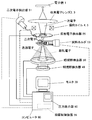
- FIG. 1 is a schematic configuration diagram of a scanning fluoroscopic electron microscope according to an embodiment of the present invention.
- the schematic block diagram of the sample holder 53 which concerns on embodiment of this invention.
- the schematic diagram of the division of each room provided in the lens body of the electron microscope which concerns on embodiment of this invention.
- the schematic block diagram of the pressure display part 90 which concerns on embodiment of this invention.
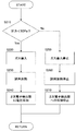
- the flowchart of the control processing of the gas introduction apparatus 60 and the secondary electron detector 51 which concern on embodiment of this invention.
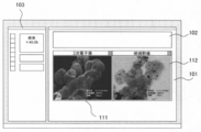
- FIG. An example of the display screen of the monitor 39 which concerns on embodiment of this invention.
- FIG. The figure which shows an example of the image display part 101 at the time of displaying a secondary electron image on the window 111, and displaying the bright field image on the window 112.
- the figure which shows an example at the time of switching and displaying several types of images suitably on one window.
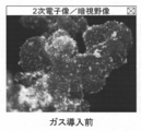
- the figure which shows an example at the time of superimposing and displaying a secondary electron image on a bright-field image The figure which shows an example at the time of superimposing and displaying a secondary electron image on a dark field image about the sample before gas introduction.
- a scanning transmission electron microscope (STEM) will be described as an example, but the present invention is an electron including a scanning electron microscope (SEM), a transmission electron microscope (TEM), and a scanning transmission electron microscope. It can be applied not only to a microscope but also to a charged particle beam apparatus.
- FIG. 1 is a schematic configuration diagram of a scanning fluoroscopic electron microscope according to an embodiment of the present invention.
- the electron microscope apparatus shown in this figure includes an electron gun 1, first and second irradiation lens coils 2 and 3, first and second deflection coils (scanning coils) 4 and 5, and an objective lens coil 6.
- MPU microprocessor
- HDD hard disk drive
- ALU arithmetic unit
- CRT controller monitor controller
- a sample holder 53 for holding the sample 70 (see FIG. 3) is disposed on the optical axis.
- the objective lens coil 6 shown in the figure is a strong excitation lens (see FIG. 4), and lenses are formed on the upper side and the lower side of the sample.
- FIG. 2 is a diagram showing an extracted main part related to the present invention in the electron microscope apparatus according to the embodiment of the present invention.
- the electron microscope section according to the present embodiment includes an electron gun 1, a converging electron lens formed by irradiation lens coils 2 and 3, and an electron beam generated by the electron gun 1 as a sample 70 (FIG. 3).
- Reference) Deflection coils (scanning coils) 4 and 5 as a scanning device to be scanned above, a sample holder 53 holding a sample 70, and an electron beam from the electron gun 1 are generated when the sample 70 is irradiated.
- a detector for detecting electrons (secondary electron detector 51, backscattered electron detector 55, dark field image detector 50 and bright field image detector 49), computer 80, and detectors 51, 55, 50, 49
- a monitor 39 for displaying a microscopic image of the sample 70 based on the output and a pressure display unit 90 for displaying the degree of vacuum of each part in the lens body are provided.
- the computer 80 records a part of the hardware shown in FIG. 1 such as the microprocessor 35, the HDD 36, the monitor controller 38, the RAM 45, the ROM 46, and the image capture interface 48, and a microscope image displayed on the monitor 39.
- the video recording control device 95 is installed.
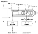
- FIG. 3 is a schematic configuration diagram of the sample holder 53 according to the embodiment of the present invention.
- the sample holder 53 includes a heater (heating device) 64, a vacuum gauge 65, and a gas introduction device 60.
- the heater 64 is composed of a wire that spans a pair of lead wires connected to a power source (not shown), and the sample 70 is attached and held on the wire. That is, the heater 64 also functions as a sample holder.
- a temperature sensor is attached to the heater 64 so that the temperature of the sample 70 can be detected.
- the output of the temperature sensor (that is, the sample temperature) is output to the computer 80 and displayed on the monitor 39 as necessary.
- the output of the heater 64 is controlled based on a control signal output to the heater 64 from a heater control device 83 mounted in the computer 80.
- the vacuum gauge 65 is for detecting the degree of vacuum (pressure) in the vicinity of the sample 70 and is installed in the sample holder 53.
- the vacuum gauge 65 is attached to the sample holder 53 so as to be located within 1 mm from the sample 70 in the example shown in the figure, but may be installed independently from the sample holder 53.
- the output of the vacuum gauge 65 (pressure in the vicinity of the sample 70) is output to the computer 80, and is displayed on the pressure display unit 90 (see FIG. 2), or control of the gas discharge amount by the gas introduction device 60 (described later). It is used for.
- FIG. 4 is a schematic diagram of compartments of each room provided in the body of the electron microscope according to the embodiment of the present invention.
- the body of the electron microscope according to the present embodiment can be classified into an electron gun chamber 71, a first intermediate chamber 72, a second intermediate chamber 73, a third intermediate chamber 74, and a sample chamber 75.
- a first orifice 76 is installed in a partition wall that divides the electron gun chamber 71 and the first intermediate chamber 72.
- a gun valve 78 is installed in a partition wall that divides the first intermediate chamber 72 and the second intermediate chamber 73.
- a second orifice 79 is installed in a partition wall provided in the second intermediate chamber, and a third orifice 84 is installed in a partition partitioning the second intermediate chamber 73 and the third intermediate chamber 74.
- the third intermediate chamber 74 and the sample chamber 75 are partitioned by the upper magnetic pole 85 of the objective lens, and the sample holder 53 is disposed between the upper magnetic pole 85 and the lower magnetic pole 86 of the objective lens in the sample chamber 75.
- a vacuum pump (ion pump) 87 a is connected to the electron gun chamber 71, a vacuum pump (ion pump) 87 b is connected to the first intermediate chamber 72, and a vacuum pump (ion ion) is connected to the second intermediate chamber 73.
- Pump) 87c is connected.
- the same vacuum pump (the turbo molecular pump 88 and the dry pump 89) is independent in the third intermediate chamber 74, the space formed between the upper magnetic pole 85 and the lower magnetic pole 86, and the space below the lower magnetic pole 86. Connected through a route.
- a secondary electron detector 51 to which a predetermined voltage (extraction voltage) is applied when detecting secondary electrons generated by the electron beam from the electron gun 1 is installed.
- Application of the voltage of the secondary electron detector 51 is controlled based on a control signal output to the secondary electron detector 51 from the detector control device 82 mounted in the computer 80.
- a vacuum gauge 77 is installed at the suction port of the turbo molecular pump 88, and the detection value of the vacuum gauge 77 is output to the computer 80.
- FIG. 5 is a schematic configuration diagram of the pressure display unit 90 according to the embodiment of the present invention.
- the pressure display unit 90 shown in this figure includes a first display unit 91 that displays a detection value of a vacuum gauge 77 installed in the vicinity of the suction port of the turbo molecular pump 88, and a vacuum gauge installed in the sample holder 53. It has the 2nd display part 92 on which 65 detected values are displayed.
- the pressure at the suction port of the turbo molecular pump 88 is 0.034 [Pa], while the pressure near the sample 70 is maintained at 1.0 [Pa]. .
- the gas introducing device 60 is for discharging gas to the sample 70 irradiated with the electron beam generated by the electron gun 1.
- the gas introduction device 60 is connected to a gas cylinder (not shown) and has a gas nozzle 61 having a tip of an injection port 63 opened in the sample holder 53, and an adjustment for adjusting the amount of gas discharged from the injection port 63.
- a valve 62 is provided.
- the injection port 63 is directed to the heater 64, and the gas from the injection port 63 is released to the sample 70 on the wire in the heater 64.
- the adjustment valve 62 is an electromagnetic valve, and the opening degree of the adjustment valve 62 is controlled based on a control signal output from the gas control device 81.
- the gas control device 81 performs gas treatment so that the degree of vacuum in the third intermediate chamber 74 in which the secondary electron detector 51 is installed is continuously maintained below the set value P1. This is for controlling the gas introduction amount (discharge amount) by the introduction device 60.
- the gas control device 81 is mounted in the computer 80.
- the output of the vacuum gauge 65 is input to the gas control device 81, and the gas control device 81 inputs a gas introduction amount (discharge amount) into the sample holder 53 based on the degree of vacuum input from the vacuum gauge 65. Is adjusted.
- the gas control device 81 holds the adjustment valve 62 at a predetermined opening and receives the input from the vacuum gauge 65.
- the pressure value is equal to or greater than the set value P1
- a process for closing the adjustment valve 62 and stopping the gas introduction device 60 from releasing the gas to the sample 70 is executed.
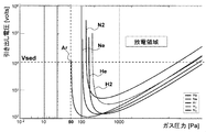
- the set value P1 relating to the control of the gas introduction amount is determined based on the value of the voltage (drawing voltage) applied to the secondary electron detector 51 and the type of gas introduced by the gas introduction device 60. It is set to a value at which no discharge occurs when the extraction voltage is applied to the secondary electron detector 51.
- FIG. 6 is a diagram showing pressure value regions in which discharge does not occur for helium (He), neon (Ne), argon (Ar), hydrogen (H 2 ), and nitrogen (N 2 ).
- Vsed is the extraction voltage value of the secondary electron detector 51 used in the present embodiment, and the region located above each curve in the graph is a region where discharge occurs (discharge region). Show.
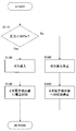
- FIG. 7 is a flowchart of control processing of the gas introduction device 60 and the secondary electron detector 51 according to the embodiment of the present invention.
- the gas control device 81 and the detector control device 82 determine whether or not the pressure value indicated by the vacuum gauge 65 is less than P1 (50 [Pa]) (S110).
- the gas control device 81 controls the opening degree of the adjustment valve 62 to a predetermined value, and the gas introduction device 60 starts introducing gas into the sample ( S120). Then, the detector control device 82 applies a drawing voltage to the secondary electron detector 51 (S130), and returns to S110. Thereby, even in a gas atmosphere, the pressure in the vicinity of the secondary electron detector 51 is maintained at less than 50 [Pa] and the occurrence of discharge is prevented. Therefore, the secondary electron image of the sample 70 in the gas atmosphere is continuously obtained. Can be obtained. Thereby, the moving image of the secondary electron image of the sample 70 in a gas atmosphere can be obtained. Since no voltage is applied when electrons are detected, an image obtained based on the detection value of a detector that does not cause discharge is naturally obtained as a moving image.
- the gas control device 81 closes the adjustment valve 62, and the gas introduction device 60 stops introducing the gas to the sample (S140). Then, the detector control device 82 stops applying the extraction voltage to the secondary electron detector 51 (S150), and returns to S110. Since the inside of the sample chamber 75 in which the sample holder 53 is housed is exhausted at a constant displacement by a vacuum pump (turbo molecular pump 88 and dry pump 89), gas introduction by the gas control device 81 is performed as described above. By stopping, the pressure in the vicinity of the sample 70 decreases toward a value less than the set value P1.
- FIG. 8 is a flowchart of control processing of the gas introduction device 60, the secondary electron detector 51, and the heater 64 according to the embodiment of the present invention.
- the gas control device 81, the detector control device 82, and the heater control device 83 determine whether or not the pressure value indicated by the vacuum gauge 65 is less than P1 (50 [Pa]). (S210).
- the gas control device 81 controls the opening degree of the adjustment valve 62 to a predetermined value, and the gas introduction device 60 starts introducing gas into the sample ( S220). Then, the heater control device 83 heats the sample 70 at a predetermined temperature by the heater 64 (S230). In addition, the detector control device 82 applies a drawing voltage to the secondary electron detector 51 (S240), and returns to S210. As a result, the pressure in the vicinity of the secondary electron detector 51 is maintained below 50 [Pa] even in a gas atmosphere to prevent the occurrence of discharge, so that the secondary electron image of the sample heated in the gas atmosphere is continuously obtained. Can be obtained. Thereby, the moving image of the secondary electron image of the sample 70 in a gas atmosphere can be obtained. Since no voltage is applied when electrons are detected, an image obtained based on the detection value of a detector that does not cause discharge is naturally obtained as a moving image.
- the gas control device 81 closes the adjustment valve 62, and the gas introduction device 60 stops introducing the gas to the sample (S250). Then, the heater control device 83 stops the heating of the sample 70 by the heater 64 (S260). In addition, the detector control device 82 stops applying the extraction voltage to the secondary electron detector 51 (S270), and returns to S210. Since the sample chamber in which the sample holder 53 is accommodated is exhausted at a constant displacement by a vacuum pump (turbo molecular pump TMP and dry pump DRP), the gas control device 81 stops gas introduction as described above. As a result, the pressure in the vicinity of the sample 70 decreases toward a value less than the set value P1.
- a vacuum pump turbo molecular pump TMP and dry pump DRP
- DACs digital-analog converters
- DACs digital-analog converters
- the electron beam generated by the electron gun 1 is converged by the first and second irradiation lens coils 2 and 3, scanned by the first and second deflection coils 4 and 5, and imaged by the objective lens coil 6.
- the sample 70 in the sample holder 53 is irradiated.
- secondary electrons excited from the electron beam (primary electrons) and generated from the sample 70 are detected by the secondary electron detector 51, and those reflected by the sample 70 (reflected electrons) are reflected electron detector 55.
- the light emitted from the sample 70 is detected by a cathodoluminescence detector (CL detector) 54, and the X-ray emitted from the sample 70 is detected by the X-ray detector 52.
- the outputs of these detectors 51, 55, 54, 52 are output to the computer via the image capturing interface 48, and are displayed on the screen of the monitor 39 as scanning images (SEM images) such as secondary electron images and reflected electron images. Is drawn as appropriate.
- those scattered and diffracted through the sample 70 are detected by the dark field detector and transmitted through the sample 70 but not scattered or diffracted (transmitted electrons).
- Is detected by a bright field detector Is detected by a bright field detector.
- the outputs of these detectors are output to a computer via the image capture interface 48 and are appropriately drawn on the screen of the monitor 39 as scanning transmission images (STEM images) such as a dark field image and a bright field image.
- FIG. 9 is an example of a display screen of the monitor 39 according to the embodiment of the present invention.
- the screen shown in this figure includes an image display unit 101 on which electron microscope images 111 and 112 are displayed, an image control unit 102 for controlling the images 111 and 112 displayed on the image display unit 101, and mainly an electron microscope.
- the image display unit 101 displays one or more electron microscope images for each window.
- the number of windows displayed on the image display unit 101 can be freely increased or decreased via the main control unit 103.
- two windows (images) 111 and 112 are displayed.
- the image control unit 102 can control an image related to a window 111 or 112 displayed on the image display unit 101 that is selected by the mouse 57 or the like (hereinafter may be referred to as a “selected window”). it can.
- FIG. 10 is an enlarged view of the image control unit 102. As shown in this figure, the image control unit 102 includes a single button 121, a secondary electronic image button 122, a bright field image button 123, a dark field image button 124, a reflected electronic image button 125, and a color button 126.
- Overlay button 131 Overlay button 131, upper image pull-down menu 132, lower image pull-down menu 133, color button 134, color button 135, transmittance input unit 136, time button 141, vacuum degree button 142, sample A temperature button 143, a time button 144, and a recording button 151 are provided.
- the selected button is displayed with “black paint”, and the unselected button is displayed with “white paint”.
- the secondary electron image detected by the secondary electron detector 51 at that time is selected as a real-time moving image. Displayed in the window.
- the bright field image button 123 is pressed, a bright field image is displayed in the selection window
- the dark field image button 124 is pressed, a dark field image is displayed in the selection window
- the reflected electron image button 125 is pressed, the selection window is displayed. A reflected electron image is displayed. Only one of these buttons 122, 123, 124, and 125 can be pressed. When a button other than the selected button is pressed, the selection of the button that has been selected is canceled. .
- the image in the selection window can be switched. Since the secondary electron image, the bright field image, the dark field image, and the reflected electron image can be alternately displayed in real time as desired by the operator, for example, the movement of the particles related to the sample 70 can be easily grasped.
- the image displayed in the selection window changes from grayscale display to pseudo color display.
- the pseudo color display corresponds to, for example, a display in which an image is displayed with a single chromatic color of green and light instead of black and white.
- the color button 126 can be selected together with the other buttons 122, 123, 124 and 125.
- the selection is canceled and the display image returns to the gray scale display.
- the shooting time of the image is displayed on the image in the selected window.
- the degree of vacuum button 142 is pressed, the degree of vacuum (pressure) of the vacuum gauge 65 related to the photographing time of the image is displayed on the image in the selection window.
- the sample temperature button 143 is pressed, the sample temperature related to the photographing time of the image is displayed on the image in the selection window.
- the time button 144 is pressed, an elapsed time from the time when the observation of the sample 70 is started to the time when the image is captured is displayed on the image in the selection window.
- the observation start time of the sample 70 is designated by the operator via the main control unit 103.
- the time, the degree of vacuum, the sample temperature, and the time are displayed on the image in the window, but these may be displayed at other places on the screen. Furthermore, if it is the information which concerns on an image, it is information other than time, a vacuum degree, sample temperature, and time (for example, the total amount of energy added to the sample 70 with the heater 64 during observation, and observation conditions of an electron microscope) Needless to say, the electron acceleration voltage, magnification, scale bar, and the like may be displayed.
- the recording button 151 is a button for storing (recording) an image (moving image) displayed in the selection window in a storage device (for example, HDD or ROM) in the computer 80.
- a recording start signal is output to the recording control device 95, and recording of a moving image in the selection window is started.
- a recording stop signal is output to the recording control device 95 and recording is stopped.
- the recording is started by pressing the recording button 151.
- the recording control device 95 may be set so as to record automatically.
- the recorded moving image may be configured to be displayed on the image display unit 101 after the observation is completed. In this case, the recorded moving image can also be displayed via the image display unit 101 and the image control unit 102.
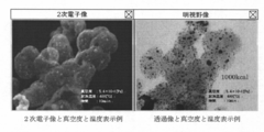
- FIG. 11 is a diagram illustrating an example of the image display unit 101 when a secondary electron image is displayed in the window 111 and a bright field image is displayed in the window 112.
- the images displayed in the windows 111 and 112 are synchronized and are created based on outputs detected at the same time by the detectors 51, 55, 49, and 50.
- the vacuum degree button 142, the sample temperature button 143 and the time button 144 are pressed for the windows 111 and 112, and the degree of vacuum, the sample temperature and the time are displayed on the images in the windows 111 and 112. Is displayed.
- a three-dimensional change in the sample can be observed. For example, among the particles related to the sample 70, those present on the surface of the sample 70 move. Thus, it can be observed that the sample sinks from the sample surface into the sample.
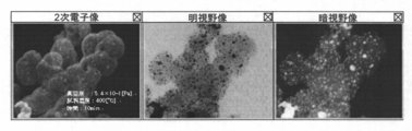
- FIG. 12 is a diagram showing an example in which three windows 111, 112, and 113 are displayed on the image display unit 101 at the same time. It is possible to easily confirm that particles existing on the surface of the sample have moved from the sample surface to the inside of the sample. It is. In the example shown in this figure, a dark field image is displayed in the added window 113.
- a reflected electron image may be displayed on the image display unit 101 by adding a window or replacing the other image. Since the reflected electron image has the surface and the inside of the sample, an image in which the secondary electron image and the dark field image are combined can be acquired.
- FIG. 13 is a diagram showing an example of a case where a plurality of types of images are appropriately switched and displayed on one window.
- Selection of an image to be displayed on the selection window can be performed by pressing a secondary electron image button 122, a bright field image button 123, a dark field image button 124, and a reflected electron image button 125. it can.
- any one of the secondary electron image, the bright field image, the dark field image, and the reflected electron image at the same time can be displayed on the selection window.
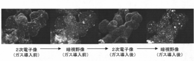
- the secondary electron image is switched to the dark field image before the gas introduction, and the secondary electron image is switched to the dark field image after the gas introduction.
- the image type is switched in real time during observation, for example, the particle movement related to the sample 70 can be easily grasped visually.
- any two of the secondary electron image, the bright field image, the dark field image, and the reflected electron image are selected. Can be displayed superimposed on each other.
- the upper image pull-down menu 132 is used to select an image to be displayed on the window in which the overlay button 131 is pressed from a secondary electron image, a bright field image, a dark field image, and a reflected electron image.
- the secondary electron image is selected.
- the lower image pull-down menu 133 is used to select an image to be displayed below from the secondary electron image, the bright field image, the dark field image, and the reflected electron image in the window in which the overlay button 131 is pressed.
- a dark field image is selected.
- the single button 121 is used when returning from the superimposed display to the single display when the selection window is superimposed and displayed by the overlay button 131.
- the image displayed in the selection window when returning to the single display is the buttons (secondary electronic image button 122, bright field image button 123, dark field image button 124, reflected electronic image button 125) pressed at the time of return. And the color button 126).
- the transmittance input unit 136 is used to set and change the transmittance of the one that is positioned above the two microscope images displayed superimposed on the selection window (the image selected by the upper image pull-down menu 132). In the example of FIG. 10, the transmittance is set to 50%. The transmittance setting by the transmittance input unit 136 is reflected in real time on the upper image in the selection window.
- the color button 134 is for displaying the image selected in the upper image pull-down menu 132 in color.
- the color button 135 is for displaying the image selected by the lower image pull-down menu 133 in color.
- the color buttons 134 and 135 are pressed, the lower image changes from grayscale display to color display.
- the color buttons 134 and 135 are pressed again, the selection is canceled and the image returns to the gray scale display.
- FIG. 14 is a diagram showing an example in which a secondary electron image is displayed overlaid on a dark field image
- FIG. 15 is an example in which a secondary electron image is displayed overlaid on a bright field image.
- FIG. 14 is a diagram showing an example in which a secondary electron image is displayed overlaid on a dark field image
- FIG. 15 is an example in which a secondary electron image is displayed overlaid on a bright field image.
- FIG. 14 is a diagram showing an example in which a secondary electron image is displayed overlaid on a dark field image
- FIG. 15 is an example in which a secondary electron image is displayed overlaid on a bright field image.
- FIG. 16 is a diagram showing an example in which a secondary electron image (color) is superimposed on a dark field image (grayscale) for a sample before gas introduction
- FIG. 17 shows a sample after gas introduction
- FIG. 18 is a diagram showing an example of a case where a secondary electron image (color) is superimposed and displayed on a dark field image (gray scale)
- FIG. 18 is a diagram above the bright field image (gray scale) of the sample after gas introduction. It is a figure which shows an example at the time of superimposing and displaying a secondary electron image (color).
- the two images expressed in grayscale When two images expressed in grayscale are superimposed, if the portion expressed in black with close density in the two images happens to be in the same or close location, the two images can be distinguished. It may disappear. However, when the grayscale image and the color image are superimposed and displayed in one window in this way, the image can be distinguished by the difference in color. For example, on which image the same particle is expressed. Can be easily determined, and the position of the particle can be easily grasped.
- the gas introduction device 60 is controlled based on the detection value of the vacuum gauge 65 installed in the vicinity of the sample 70, but in the vicinity of the secondary electron detector 51 (for example, the first in FIG. 4). 3)
- the vacuum gauge 65 is installed in the intermediate chamber 74), and discharge can be prevented from occurring even if the gas introduction device 60 is controlled based on the detected value.
- the degree of vacuum in the vicinity of the sample 70 is a measure of the mass (Mass) of the gas blown to the sample 70, the amount of energy burned in the sample 70 can be calculated based on the heated temperature and the degree of vacuum.
- the secondary electron detector 51 has the relationship that the third intermediate chamber 74 in which the secondary electron detector 51 is housed is exhausted by the vacuum pumps 88 and 89 in a path independent of the vicinity of the sample 70. Since the degree of vacuum is not worse than the vicinity of the sample 70, there is no problem in gas control.
- a vacuum gauge is installed in the vicinity of the secondary electron detector 51, the amount of energy is calculated based on the vacuum gauge in the vicinity of the sample 70, and the vacuum gauge in the vicinity of the secondary electron detector 51. The gas control may be performed based on the above.
- the present invention can be applied to any electron microscope provided with a detector that needs to be considered.
- some dark field detectors are of a type that once scatters an electron beam on a conversion plate (gold vapor-deposited plate) and draws it with an extraction voltage. Since a voltage is applied in the same manner as the secondary electron detector 51 in the present embodiment and discharge may occur depending on the degree of vacuum, the present invention can be applied.
- the gas introduction device 60 is attached in the sample holder 53, but if the gas can be introduced into the sample 70 in the sample holder 53, the gas introduction device 60 is installed independently of the sample holder 53. It doesn't matter.
- the present invention is not limited to the above-described embodiment, and includes various modifications within the scope not departing from the gist thereof.
- the present invention is not limited to the one having all the configurations described in the above embodiment, and includes a configuration in which a part of the configuration is deleted.
- part of the configuration according to one embodiment can be added to or replaced with the configuration according to another embodiment.
- each configuration relating to the above-described computer and various control devices, functions and execution processing of each configuration, etc. are partly or entirely hardware (for example, logic for executing each function is designed by an integrated circuit, etc.) It may be realized with.
- the configuration related to the computer and the various control devices is a program (software) that is read and executed by an arithmetic processing device (for example, a CPU) to realize each function related to the configuration of the computer and the various control devices. Also good.
- Information related to the program can be stored in, for example, a semiconductor memory (flash memory, SSD, etc.), a magnetic storage device (hard disk drive, etc.), a recording medium (magnetic disk, optical disc, etc.), and the like.
- control line and the information line are shown to be understood as necessary for the description of the embodiment, but all the control lines and information lines related to the product are not necessarily included. It does not always indicate. In practice, it can be considered that almost all the components are connected to each other.
- SYMBOLS 1 Electron gun, 2 ... 1st irradiation lens coil, 3 ... 2nd irradiation lens coil, 4 ... 1st deflection coil, 5 ... 2nd deflection coil, 6 ... Objective lens coil, 7 ... 1st electromagnetic sample image movement Coil, 8 ... second electromagnetic sample image moving coil, 9 ... first intermediate lens coil, 10 ... second intermediate lens coil, 11 ... first projection lens coil, 12 ... second projection lens coil, 13-23 ... Excitation power supply, 24-34 ... DAC, 35 ... Microprocessor, 36 ... Storage device, 37 ... Calculation device, 38 ... Monitor controller, 39 ... Monitor, 40-41 ... I / F, 42 ...
- Rotary encoder for magnification switching 43 ... Rotary encoder for input, 44 ... Keyboard, 45 ... RAM, 46 ... ROM, 47 ... Scanned image capture interface 48, 48 ... Image capture interface 49 ... Bright field image detector, 50 ... Dark field image detector, 51 ... Secondary electron detector, 52 ... X-ray detector, 53 ... Sample stage, 54 ... CL detector, 55 ... Backscattered electron detector 59 ... Heating heater, 60 ... Gas introduction device, 62 ... Adjustment valve, 63 ... Injection port, 64 ... Heating heater, 65 ... Vacuum gauge, 70 ... Sample, 77 ... Vacuum gauge, 81 ... Gas control device, 82 ... Detection Control device, 83 ... heater control device, 90 ... pressure display unit, 95 ... recording control device, 101 ... image display unit
Landscapes
- Chemical & Material Sciences (AREA)
- Analytical Chemistry (AREA)
- Analysing Materials By The Use Of Radiation (AREA)
Abstract
Description
図12は3つのウィンドウ111,112,113を画像表示部101に同時に表示した場合の一例を示す図である。この図に示した例では、追加したウィンドウ113に暗視野像を表示している。このように同時刻に検出された2次電子像、明視野像および暗視野像を同時に表示すると、試料70の表面、内部および背面を同時に観察することができ、例えば、試料70に係る粒子が表面、内部、背面のいずれに位置しているかを容易に把握することができる。なお、ウィンドウを追加して又は他の像に代えて、画像表示部101に反射電子像を表示しても良い。反射電子像は、試料の表面と内部があるため、2次電子像と暗視野像が合わさったような画像が取得できる。
Claims (12)
- 電子銃からの電子線が試料に照射されることで発生する電子を検出する検出器と、
当該検出器の出力に基づいて前記試料の顕微鏡像を表示する表示装置と
前記試料にガスを放出するためのガス導入装置と、
当該ガス導入装置によるガス放出中に、前記検出器が設置された空間内の真空度が継続的に設定値未満に保持されるように前記ガス導入装置によるガス放出量を制御するガス制御装置とを備えることを電子顕微鏡。 - 請求項1に記載の電子顕微鏡において、
前記検出器には、前記電子線により発生する電子を検出する際に電圧が印加され、
前記設定値は、前記検出器に前記電圧が印加されても放電が発生しない値に設定されていることを特徴とする電子顕微鏡。 - 請求項1に記載の電子顕微鏡において、
前記検出器は、前記電子線により発生する電子を検出する2次電子検出器であり、
前記顕微鏡像は、前記2次電子検出器によって検出される2次電子像であることを特徴とする電子顕微鏡。 - 請求項1に記載の電子顕微鏡において、
前記検出器は、前記電子線により発生する電子を検出する2次電子検出器と、前記電子線に係る電子のうち前記試料を透過したものを検出する明視野検出器及び暗視野検出器であり、
前記表示装置は、前記顕微鏡像として、前記2次電子検出器によって検出される2次電子像と、当該2次電子像と同時刻に前記明視野検出器又は前記暗視野検出器によって検出される顕微鏡像とを表示することを特徴とする電子顕微鏡。 - 請求項1に記載の電子顕微鏡において、
前記検出器は、前記電子線により発生する電子を検出する反射電子検出器であり、
前記顕微鏡像は、前記反射電子検出器によって検出される反射電子像であることを特徴とする電子顕微鏡。 - 請求項1に記載の電子顕微鏡において、
前記表示装置には、さらに、前記顕微鏡像の撮影時刻、当該撮影時刻に係る前記試料の近傍の真空度及び前記試料の温度のうち少なくとも1つが表示されることを特徴とする電子顕微鏡。 - 請求項4に記載の電子顕微鏡において、
前記表示装置には、前記2次電子検出器によって検出される2次電子像と、当該2次電子像と同時刻に前記明視野検出器又は前記暗視野検出器によって検出される顕微鏡像とが同時に表示されることを特徴とする電子顕微鏡。 - 請求項4に記載の電子顕微鏡において、
前記表示装置は、前記2次電子検出器によって検出される2次電子像と、当該2次電子像と同時刻に前記明視野検出器によって検出される明視野像と、当該2次電子像と同時刻に前記暗視野検出器によって検出される暗視野像のうちいずれか1つが表示される表示部を有し、当該表示部に表示される顕微鏡像は選択可能であることを特徴とする電子顕微鏡。 - 請求項4に記載の電子顕微鏡において、
前記表示装置は、前記2次電子検出器によって検出される2次電子像と、当該2次電子像と同時刻に前記明視野検出器によって検出される明視野像と、当該2次電子像と同時刻に前記暗視野検出器によって検出される暗視野像のうちいずれか2つが重ね合わせて表示される表示部を有し、
当該表示部に重ね合わせて表示される2つの顕微鏡像のうち上に位置するものの透過率は変更可能であることを特徴とする電子顕微鏡。 - 請求項9に記載の電子顕微鏡において、
前記表示部に重ね合わせて表示される2つの顕微鏡のうち一方は、カラーで表示されることを特徴とする電子顕微鏡。 - 請求項1から10のいずれかに記載の電子顕微鏡において、
前記表示装置に表示される顕微鏡像を録画する録画装置をさらに備えることを特徴とする電子顕微鏡。 - 電子銃で発生された電子線が試料に照射される際に発生する電子を検出する検出器が設置された空間内の真空度が、継続的に設定値未満に保持されるように前記試料に放出するガス放出量を制御し、
前記電子線の照射時に発生する電子を前記検出器で検出して、当該検出器の出力に基づいて顕微鏡像を表示装置に表示することを特徴とする電子顕微鏡による試料観察方法。
Priority Applications (3)
| Application Number | Priority Date | Filing Date | Title |
|---|---|---|---|
| DE112014001796.5T DE112014001796B4 (de) | 2013-04-02 | 2014-03-20 | Elektronenmikroskop und Probenbeobachtungsverfahren |
| CN201480018726.6A CN105103263B (zh) | 2013-04-02 | 2014-03-20 | 电子显微镜和试样观察方法 |
| US14/781,634 US10083814B2 (en) | 2013-04-02 | 2014-03-20 | Electron microscope and sample observation method |
Applications Claiming Priority (2)
| Application Number | Priority Date | Filing Date | Title |
|---|---|---|---|
| JP2013077175A JP6215557B2 (ja) | 2013-04-02 | 2013-04-02 | 電子顕微鏡 |
| JP2013-077175 | 2013-04-02 |
Publications (1)
| Publication Number | Publication Date |
|---|---|
| WO2014162901A1 true WO2014162901A1 (ja) | 2014-10-09 |
Family
ID=51658200
Family Applications (1)
| Application Number | Title | Priority Date | Filing Date |
|---|---|---|---|
| PCT/JP2014/057874 Ceased WO2014162901A1 (ja) | 2013-04-02 | 2014-03-20 | 電子顕微鏡及び試料観察方法 |
Country Status (5)
| Country | Link |
|---|---|
| US (1) | US10083814B2 (ja) |
| JP (1) | JP6215557B2 (ja) |
| CN (1) | CN105103263B (ja) |
| DE (1) | DE112014001796B4 (ja) |
| WO (1) | WO2014162901A1 (ja) |
Families Citing this family (4)
| Publication number | Priority date | Publication date | Assignee | Title |
|---|---|---|---|---|
| JP6117070B2 (ja) * | 2013-09-26 | 2017-04-19 | 株式会社日立ハイテクノロジーズ | 電子顕微鏡 |
| JP6698867B2 (ja) * | 2016-11-22 | 2020-05-27 | 株式会社日立ハイテク | 荷電粒子線装置および試料観察方法 |
| CN114175206A (zh) * | 2019-07-26 | 2022-03-11 | Asml荷兰有限公司 | 多着陆能量扫描电子显微镜系统和方法 |
| EP4369376A1 (en) * | 2022-06-24 | 2024-05-15 | FEI Company | Improved transmission electron microscopy |
Citations (6)
| Publication number | Priority date | Publication date | Assignee | Title |
|---|---|---|---|---|
| JPH10134751A (ja) * | 1996-10-29 | 1998-05-22 | Nikon Corp | 環境制御型の走査型電子顕微鏡 |
| JP2000241372A (ja) * | 1999-02-24 | 2000-09-08 | Canon Inc | 表面観察装置 |
| JP2002083564A (ja) * | 2000-09-05 | 2002-03-22 | Hitachi Ltd | 微小部分析装置及び分析方法 |
| JP2004335242A (ja) * | 2003-05-07 | 2004-11-25 | Jeol Ltd | 試料観察装置 |
| JP2007214088A (ja) * | 2006-02-13 | 2007-08-23 | Hitachi High-Technologies Corp | 集束イオンビーム加工観察装置および試料加工方法、試料観察方法 |
| JP2009099468A (ja) * | 2007-10-18 | 2009-05-07 | Hitachi High-Technologies Corp | 荷電粒子線応用装置 |
Family Cites Families (8)
| Publication number | Priority date | Publication date | Assignee | Title |
|---|---|---|---|---|
| JPS4925814U (ja) * | 1972-06-09 | 1974-03-05 | ||
| US5578823A (en) * | 1994-12-16 | 1996-11-26 | Hitachi, Ltd. | Transmission electron microscope and method of observing element distribution by using the same |
| JPH09196831A (ja) | 1996-01-19 | 1997-07-31 | Hitachi Ltd | 試料冷却観察装置 |
| JP2003100248A (ja) * | 2001-09-25 | 2003-04-04 | Hitachi Ltd | 荷電粒子線を用いたパターン検査装置 |
| US7053370B2 (en) * | 2001-10-05 | 2006-05-30 | Canon Kabushiki Kaisha | Information acquisition apparatus, cross section evaluating apparatus, cross section evaluating method, and cross section working apparatus |
| JP2003187735A (ja) | 2001-12-18 | 2003-07-04 | Jeol Ltd | 試料ホルダ |
| JP4014916B2 (ja) * | 2002-04-11 | 2007-11-28 | 株式会社キーエンス | 電子顕微鏡、電子顕微鏡の操作方法、電子顕微鏡操作プログラムおよびコンピュータで読み取り可能な記録媒体 |
| JP4850654B2 (ja) * | 2006-10-23 | 2012-01-11 | 株式会社日立ハイテクノロジーズ | 荷電粒子線装置および荷電粒子線装置用試料保持装置 |
-
2013
- 2013-04-02 JP JP2013077175A patent/JP6215557B2/ja not_active Expired - Fee Related
-
2014
- 2014-03-20 CN CN201480018726.6A patent/CN105103263B/zh not_active Expired - Fee Related
- 2014-03-20 DE DE112014001796.5T patent/DE112014001796B4/de not_active Expired - Fee Related
- 2014-03-20 WO PCT/JP2014/057874 patent/WO2014162901A1/ja not_active Ceased
- 2014-03-20 US US14/781,634 patent/US10083814B2/en active Active
Patent Citations (6)
| Publication number | Priority date | Publication date | Assignee | Title |
|---|---|---|---|---|
| JPH10134751A (ja) * | 1996-10-29 | 1998-05-22 | Nikon Corp | 環境制御型の走査型電子顕微鏡 |
| JP2000241372A (ja) * | 1999-02-24 | 2000-09-08 | Canon Inc | 表面観察装置 |
| JP2002083564A (ja) * | 2000-09-05 | 2002-03-22 | Hitachi Ltd | 微小部分析装置及び分析方法 |
| JP2004335242A (ja) * | 2003-05-07 | 2004-11-25 | Jeol Ltd | 試料観察装置 |
| JP2007214088A (ja) * | 2006-02-13 | 2007-08-23 | Hitachi High-Technologies Corp | 集束イオンビーム加工観察装置および試料加工方法、試料観察方法 |
| JP2009099468A (ja) * | 2007-10-18 | 2009-05-07 | Hitachi High-Technologies Corp | 荷電粒子線応用装置 |
Also Published As
| Publication number | Publication date |
|---|---|
| US20160064183A1 (en) | 2016-03-03 |
| US10083814B2 (en) | 2018-09-25 |
| CN105103263A (zh) | 2015-11-25 |
| JP6215557B2 (ja) | 2017-10-18 |
| CN105103263B (zh) | 2017-06-09 |
| JP2014203594A (ja) | 2014-10-27 |
| DE112014001796T5 (de) | 2016-01-21 |
| DE112014001796B4 (de) | 2020-03-26 |
Similar Documents
| Publication | Publication Date | Title |
|---|---|---|
| US8993961B2 (en) | Electric charged particle beam microscope and electric charged particle beam microscopy | |
| KR101810437B1 (ko) | 하전입자선 장치, 시료 화상 취득 방법, 및 프로그램 기록 매체 | |
| CN105359249B (zh) | 能够用ebsd检测器容易地分析所期望位置的带电粒子线装置以及其控制方法 | |
| JP6215557B2 (ja) | 電子顕微鏡 | |
| JP6698867B2 (ja) | 荷電粒子線装置および試料観察方法 | |
| US10157727B2 (en) | Aberration measurement in a charged particle microscope | |
| CN104838466B (zh) | 带电粒子束装置及其方法 | |
| KR20180007695A (ko) | 프티코그래피를 이용한 시료 이미징 방법 | |
| JP7026568B2 (ja) | 荷電粒子顕微鏡法の革新的な画像処理 | |
| CN111354612B (zh) | 操作气体供应装置的方法、气体供应装置和粒子辐射设备 | |
| JP6117070B2 (ja) | 電子顕微鏡 | |
| JP6097863B2 (ja) | 荷電粒子線装置、試料画像取得方法、およびプログラム記録媒体 | |
| JP7844271B2 (ja) | ビームによる試料損傷を低減した走査型透過荷電粒子顕微鏡を使用して試料を調査する方法およびシステム | |
| US20250323012A1 (en) | Method for obtaining a tilt series of images of a sample at a plurality of tilt angles | |
| JP4863886B2 (ja) | 電子線応用装置および電子源の安定稼動状態判定方法 | |
| JP2013254574A (ja) | 荷電粒子線観察装置および試料観察方法 |
Legal Events
| Date | Code | Title | Description |
|---|---|---|---|
| WWE | Wipo information: entry into national phase |
Ref document number: 201480018726.6 Country of ref document: CN |
|
| 121 | Ep: the epo has been informed by wipo that ep was designated in this application |
Ref document number: 14778584 Country of ref document: EP Kind code of ref document: A1 |
|
| WWE | Wipo information: entry into national phase |
Ref document number: 14781634 Country of ref document: US |
|
| WWE | Wipo information: entry into national phase |
Ref document number: 112014001796 Country of ref document: DE Ref document number: 1120140017965 Country of ref document: DE |
|
| 122 | Ep: pct application non-entry in european phase |
Ref document number: 14778584 Country of ref document: EP Kind code of ref document: A1 |