WO2014162670A1 - Air blowing device - Google Patents
Air blowing device Download PDFInfo
- Publication number
- WO2014162670A1 WO2014162670A1 PCT/JP2014/001490 JP2014001490W WO2014162670A1 WO 2014162670 A1 WO2014162670 A1 WO 2014162670A1 JP 2014001490 W JP2014001490 W JP 2014001490W WO 2014162670 A1 WO2014162670 A1 WO 2014162670A1
- Authority
- WO
- WIPO (PCT)
- Prior art keywords
- air
- airflow
- door
- outlet
- duct
- Prior art date
Links
Images


Classifications
-
- B—PERFORMING OPERATIONS; TRANSPORTING
- B60—VEHICLES IN GENERAL
- B60S—SERVICING, CLEANING, REPAIRING, SUPPORTING, LIFTING, OR MANOEUVRING OF VEHICLES, NOT OTHERWISE PROVIDED FOR
- B60S1/00—Cleaning of vehicles
- B60S1/02—Cleaning windscreens, windows or optical devices
- B60S1/023—Cleaning windscreens, windows or optical devices including defroster or demisting means
-
- B—PERFORMING OPERATIONS; TRANSPORTING
- B60—VEHICLES IN GENERAL
- B60H—ARRANGEMENTS OF HEATING, COOLING, VENTILATING OR OTHER AIR-TREATING DEVICES SPECIALLY ADAPTED FOR PASSENGER OR GOODS SPACES OF VEHICLES
- B60H1/00—Heating, cooling or ventilating [HVAC] devices
- B60H1/34—Nozzles; Air-diffusers
- B60H1/3414—Nozzles; Air-diffusers with means for adjusting the air stream direction
-
- B—PERFORMING OPERATIONS; TRANSPORTING
- B60—VEHICLES IN GENERAL
- B60H—ARRANGEMENTS OF HEATING, COOLING, VENTILATING OR OTHER AIR-TREATING DEVICES SPECIALLY ADAPTED FOR PASSENGER OR GOODS SPACES OF VEHICLES
- B60H1/00—Heating, cooling or ventilating [HVAC] devices
- B60H1/34—Nozzles; Air-diffusers
- B60H1/345—Nozzles; Air-diffusers with means for adjusting divergence, convergence or oscillation of air stream
-
- B—PERFORMING OPERATIONS; TRANSPORTING
- B60—VEHICLES IN GENERAL
- B60S—SERVICING, CLEANING, REPAIRING, SUPPORTING, LIFTING, OR MANOEUVRING OF VEHICLES, NOT OTHERWISE PROVIDED FOR
- B60S1/00—Cleaning of vehicles
- B60S1/02—Cleaning windscreens, windows or optical devices
- B60S1/54—Cleaning windscreens, windows or optical devices using gas, e.g. hot air
- B60S1/544—Cleaning windscreens, windows or optical devices using gas, e.g. hot air moving gas spreading means, e.g. arranged in wiper arms
Definitions
- This disclosure relates to an air blowing device that blows air into a space to be air-conditioned.
- Patent Document 1 discloses an air blowing device in which a defroster outlet that blows air toward a windshield of a vehicle and an outlet that blows air toward the vehicle interior are used in common.
- the air blowing device includes a duct connected to the air outlet, a guide wall provided at least on the passenger compartment side of the air outlet side portion of the duct, a nozzle provided inside the duct, and an air flow upstream side of the nozzle. And a control flow outlet for blowing out the control flow.
- the guide wall has a convex curved shape.
- the nozzle is used to form a high-speed air flow by narrowing the main flow.
- the control flow outlets are provided on both sides of the vehicle front side and the vehicle rear side, and are configured such that the control flow is blown out from only one of the control flow outlets.
- the direction of the air blown from the blowout port is switched by the control flow. That is, by blowing out a control flow from the rear of the vehicle toward the front of the vehicle, a high-speed air flow from the nozzle is drawn toward the front of the vehicle. Thereby, air blows off toward a windshield from a blower outlet. On the other hand, by blowing a control flow from the front of the vehicle toward the rear of the vehicle, a high-speed air flow from the nozzle is drawn toward the rear of the vehicle. Thus, the high-speed airflow is bent by flowing along the guide wall due to the Coanda effect, and air is blown out from the outlet toward the vehicle interior.
- the present disclosure aims to provide an air blowing device capable of switching the blowing direction of the air blown from the blower outlet and capable of increasing the bending angle when blowing the air from the blower outlet.
- an air blowing device includes an air outlet that blows air into a target space, a duct that is connected to the air outlet and has an air flow path formed therein, and an airflow deflecting member that is provided inside the duct. .
- the air flow paths on one side and the other side sandwiching the airflow deflecting member inside the duct are defined as the one side flow path and the other side flow path, respectively.
- the airflow deflecting member forms a high-speed airflow in the one-side flow path by making the flow-path cross-sectional area ratio of the one-side flow path smaller than the flow-path cross-sectional area ratio of the other-side flow path.
- the first state in which a low-speed air flow is formed and the second state in which an air flow different from the first state is formed inside the duct are configured to be switchable.
- the duct is provided with a guide wall that bends a high-speed airflow from the one-side flow path along the wall surface on one side wall in the outlet side portion.
- the blowing direction of the air blown out from the blowout port can be switched.
- the first state high-speed airflow from the one-side flow path flows along the guide wall, so that the air flowing in the duct is bent to one side and blown out from the outlet.
- the second state the air flowing in the duct is not bent to one side, or is bent to one side at a bending angle smaller than that in the first state and blown out from the outlet.
- a high-speed airflow is formed in the one-side flow path, thereby generating a negative pressure on the airflow downstream side of the airflow deflecting member.
- the low-speed airflow of the other side channel is drawn into the airflow downstream side of the airflow deflecting member, and the low-speed airflow merges with the high-speed airflow while bending to the high-speed airflow side.
- FIG. 1 It is a schematic diagram which shows the air blowing apparatus and air-conditioning unit which concern on 1st Embodiment. It is a schematic diagram which shows the structure of the air conditioning unit of FIG. It is an enlarged view of the blower outlet and duct of FIG. 1 at the time of face mode. It is an enlarged view of the blower outlet and duct of FIG. 1 at the time of a defroster mode. It is an enlarged view of the blower outlet and duct of FIG. 1 at the time of a defroster mode. It is a figure which shows the vehicle mounting state of the air conditioning unit which concerns on a comparative example. It is a schematic diagram which shows the airflow from the face blower outlet of a comparative example.
- FIG. 24 is a sectional view taken along line XXIV-XXIV in FIG. 23.
- FIG. 24 is a sectional view taken along line XXV-XXV in FIG. 23.
- FIG. 25 is an enlarged view of a region XXVI in FIG. 24.
- It is sectional drawing which shows the modification with respect to 13th Embodiment.
- It is sectional drawing which shows the positional relationship of the cover and guide wall of the air blowing apparatus which concern on 14th Embodiment.
- FIG. 30 is a plan view of the cover in FIG. 29.
- FIG. 31 is a sectional view taken along the line XXXI-XXXI in FIG. 30. It is a schematic diagram which shows the air blowing apparatus which concerns on 16th Embodiment. It is the figure which looked at the inside of the duct in FIG. 32 from the top. It is EE sectional drawing in FIG. It is EE sectional drawing in FIG. It is EE sectional drawing in FIG. It is a block diagram of the electric control part of the air blowing apparatus which concerns on 16th Embodiment. It is a top view which shows the air blowing direction from the blower outlet at the time of the normal mode of the air blowing apparatus which concerns on 16th Embodiment. It is EE sectional drawing in FIG.
- FIG. 56 It is a schematic diagram which shows the air blowing apparatus which concerns on 20th Embodiment. It is a schematic diagram which shows the air blowing apparatus which concerns on 20th Embodiment. It is a perspective view which shows the air blowing apparatus which concerns on other embodiment. It is the figure which looked at the cover and duct inside in FIG. 56 from the top.
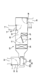
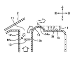
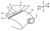
- the air blowing device is applied to an air outlet and a duct of an air conditioning unit mounted in front of the vehicle.
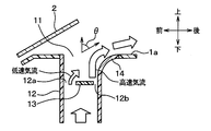
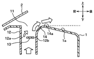
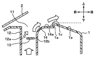
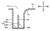
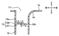
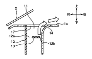
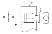
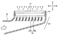
- the air blowing device 10 includes an air outlet 11 provided on the windshield 2 side of the upper surface 1 a of the instrument panel 1, a duct 12 that connects the air outlet 11 and the air conditioning unit 20, and a duct 12 and an airflow deflecting door 13 disposed in the inside.
- the blower outlet 11 blows out temperature-adjusted air by switching the three blowout modes of the defroster mode, the upper vent mode, and the face mode by the airflow deflecting door 13.
- the defroster mode is a blowing mode in which air is blown out toward the windshield 2 to clear the cloudiness of the window.
- the face mode is a blowing mode that blows air toward the upper body of the front seat passenger.
- the upper vent mode is a blow-out mode in which air is blown upward from the face mode and blown to the rear seat occupant.
- the air outlet 11 has an elongated shape in the vehicle width direction and is arranged over the front of the driver seat and the front of the passenger seat. In addition, the vehicle width direction length of the blower outlet 11 and the arrangement
- the air outlet 11 is formed by a terminal opening of the duct 12.
- the duct 12 forms an air flow path through which air blown from the air conditioning unit 20 flows.
- the duct 12 is made of a resin that is configured separately from the air conditioning unit 20, and is connected to the air conditioning unit 20.
- the duct 12 is connected to the defroster / face opening 30 of the air conditioning unit 20.
- the duct 12 may be formed integrally with the air conditioning unit 20.
- the airflow deflecting door 13 is an airflow deflecting member that deflects the speed of the airflow inside the duct 12. In other words, the airflow deflection door 13 is closer to the vehicle rear side than the airflow deflection door 13 inside the duct 12 and the airflow deflection door 13 inside the duct 12.
- the airflow velocity of the front flow passage 12a and the air flow velocity of the rear flow passage 12b are made different.
- the rear side flow path 12b on the vehicle rear side corresponds to one side flow path
- the front side flow path 12a on the vehicle front side corresponds to the other side flow path.
- a sliding door 131 that is slidable in the vehicle front side and the vehicle rear side is employed as the airflow deflecting door 13.
- the sliding door 131 has a length in the front-rear direction of the vehicle that is smaller than the width of the duct 12 in the front-rear direction of the vehicle, and is long enough to form the front-side channel 12a and the rear-side channel 12b.
- the sliding door 131 slides in the front-rear direction to form a high-speed air flow (jet) in the rear-side flow path 12b and a first state in which a low-speed air flow is formed in the front-side flow path 12a, and the duct 12 It is possible to switch between a second state in which an air flow different from the first state is formed inside.
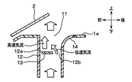
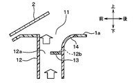
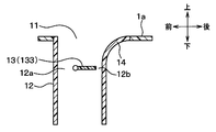
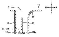
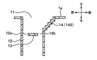
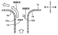
- the duct 12 is provided with a guide wall 14 on the wall on the vehicle rear side of the outlet 11 side portion.
- the guide wall 14 is continuous with the upper surface 1 a of the instrument panel 1.
- the guide wall 14 is for guiding a high-speed air flow along the wall surface to the vehicle rear side.
- the guide wall 14 has a shape that widens the width of the air flow path in the air outlet 11 side portion of the duct 12 toward the downstream side of the air flow.
- a guide wall 141 having a curved wall surface is employed as the guide wall 14.
- the air conditioning unit 20 is disposed inside the instrument panel 1 disposed in front of the front seat in the passenger compartment. As shown in FIG. 2, the air conditioning unit 20 includes an air conditioning casing 21 that forms an outer shell.
- the air conditioning casing 21 constitutes an air passage that guides air to the vehicle interior, which is the air conditioning target space.
- the inside air inlet 22, the outside air inlet 23, and the inlet opening / closing door 24 constitute an inside / outside air switching unit that switches the intake air into the air conditioning casing 21 between the inside air and the outside air.
- the operation of the inlet opening / closing door 24 is controlled by a control signal output from a control device (not shown).
- a blower 25 serving as a blower that blows air into the passenger compartment is disposed on the downstream side of the air flow of the suction opening / closing door 24.
- the blower 25 of the present embodiment is an electric blower that drives a centrifugal multiblade fan (sirocco fan) 25a by an electric motor 25b that is a drive source, and the number of rotations (air flow rate) is controlled by a control signal output from a control device (not shown). ) Is controlled.
- the evaporator 26 that functions as a cooling unit that cools the air blown by the blower 25 is disposed on the downstream side of the air flow of the blower 25.
- the evaporator 26 is a heat exchanger that exchanges heat between the refrigerant flowing through the inside and the blown air, and constitutes a vapor compression refrigeration cycle together with a compressor, a condenser, an expansion valve, and the like (not shown).
- a heater core 27 that functions as a heating unit that heats the air cooled by the evaporator 26 is disposed on the downstream side of the air flow of the evaporator 26.
- the heater core 27 of the present embodiment is a heat exchanger that heats air using the cooling water of the vehicle engine as a heat source.
- the evaporator 26 and the heater core 27 constitute a temperature adjusting unit that adjusts the temperature of the air blown into the passenger compartment.
- a cold air bypass passage 28 is formed on the downstream side of the air flow of the evaporator 26 to allow the air after passing through the evaporator 26 to flow around the heater core 27.
- the temperature of the blown air mixed on the air flow downstream side of the heater core 27 and the cold air bypass passage 28 varies depending on the air volume ratio of the blown air passing through the heater core 27 and the blown air passing through the cold air bypass passage 28.
- an air mix door 29 is arranged on the downstream side of the air flow of the evaporator 26 and on the inlet side of the heater core 27 and the cold air bypass passage 28.
- the air mix door 29 continuously changes the air volume ratio of the cold air flowing into the heater core 27 and the cold air bypass passage 28, and functions as a temperature adjusting unit together with the evaporator 26 and the heater core 27.
- the operation of the air mix door 29 is controlled by a control signal output from the control device.
- a defroster / face opening 30 and a foot opening 31 are provided in the most downstream portion of the air flow of the air conditioning casing 21.
- the defroster / face opening 30 is connected to the air outlet 11 provided on the upper surface 1 a of the instrument panel 1 through the duct 12.
- the foot opening 31 is connected to the foot outlet 33 via the foot duct 32.
- a defroster / face door 34 that opens and closes the defroster / face opening 30 and a foot door 35 that opens and closes the foot opening 31 are arranged on the upstream side of the air flows of the openings 30 and 31.
- the defroster / face door 34 and the foot door 35 are blowing mode doors for switching the blowing state of air into the vehicle interior.
- the air flow deflecting door 13 is configured to be interlocked with these blowing mode doors 34 and 35 so as to be in a desired blowing mode.
- the operations of the air flow deflecting door 13 and the blowing mode doors 34 and 35 are controlled by a control signal output from the control device. Note that the airflow deflecting door 13 and the blowing mode doors 34 and 35 can be changed in position by a passenger's manual operation.
- the defroster / face door 34 closes the defroster / face opening 30 and the foot door 35 opens the foot opening 31.
- the defroster / face door 34 opens the defroster / face opening 30 and the foot door 35 closes the foot opening 31.
- the position of the airflow deflecting door 13 is a position corresponding to a desired blowing mode.
- the airflow deflection door 13 is moved in the front-rear direction, and the position of the airflow deflection door 13 is changed to change the airflow velocity of the front side flow path 12a and the rear side flow path 12b. Then, the blowing angle ⁇ is changed.
- the blowing angle ⁇ here is an angle formed by the blowing direction with respect to the vertical direction as shown in FIG.
- the reason why the vertical direction is used as a reference is that the blowing direction from the outlet 11 when the airflow deflecting door 13 is not provided in the duct 12 is the vertical direction.
- the blowing mode when the blowing mode is the face mode, the flow passage cross-sectional area ratio of the rear flow passage 12b is relatively reduced and the flow flow cross-sectional area ratio of the front flow passage 12a is relatively increased.
- the position of the airflow deflecting door 13 is the position on the vehicle rear side. Accordingly, a high-speed airflow is formed in the rear-side flow path 12b, and a low-speed airflow is formed in the front-side flow path 12a.
- the high-speed airflow is bent toward the vehicle rear side by flowing along the guide wall 14 by the Coanda effect.
- air whose temperature has been adjusted by the air conditioning unit 20, for example, cold air is blown out from the air outlet 11 toward the upper body of the occupant.
- the blowing mode when the blowing mode is the defroster mode, the flow passage cross-sectional area ratio of the front flow path 12a is relatively reduced and the flow flow cross-sectional area ratio of the rear flow path 12b is relatively increased.
- the position of the airflow deflecting door 13 is the position on the front side of the vehicle.
- a second state different from the first state that is, a high-speed airflow is formed in the front-side flow path 12a and a low-speed airflow is formed in the rear-side flow path 12b.
- the air flows upward along the vehicle front side wall of the duct 12.
- air whose temperature has been adjusted by the air conditioning unit 20, for example, warm air is blown out from the air outlet 11 toward the windshield 2.
- the occupant manually adjusts the position of the airflow deflecting door 13 or the control device automatically adjusts the speed ratio between the high-speed airflow and the low-speed airflow, and the blowing angle in the defroster mode Can be at any angle.
- the position of the airflow deflection door 13 is a position between the position of the airflow deflection door 13 in the face mode and the position of the airflow deflection door 13 in the defroster mode.
- the first state is entered, but since the speed of the high-speed airflow is lower than in the face mode, the blowing angle ⁇ is smaller than in the face mode.
- air whose temperature has been adjusted by the air conditioning unit 20, for example, cold air is blown out from the air outlet 11 toward the rear seat occupant.
- the airflow deflection door 13 changes the ratio of the channel cross-sectional area of the rear-side channel 12b and the channel cross-section of the front-side channel 12a with respect to the face mode. This is realized by adjusting the speed ratio between the airflow and the low-speed airflow. Even in the upper vent mode, the position of the airflow deflecting door 13 is manually adjusted by the occupant, or the control device automatically adjusts the speed ratio between the high-speed airflow and the low-speed airflow, The blowing angle can be set to an arbitrary angle.
- the position of the airflow deflecting door 13 may be set to the position shown in FIG. In FIG. 5, the position of the airflow deflection door 13 is set to a position where the rear side flow path 12 b is fully closed and the front side flow path 12 a is fully opened. Also in this case, since the second state different from the first state, that is, the air flows only through the front channel 12a and no high-speed airflow is formed in the rear channel 12b, It blows out toward the windshield 2. Further, the position of the airflow deflecting door 13 may be a position where the front side channel 12a is fully closed and the rear side channel 12b is fully opened, contrary to the position shown in FIG. Also in this case, since the second state different from the first state, that is, the air flows only through the rear-side flow path 12b and the high-speed airflow is not formed in the rear-side flow path 12b, Is blown out toward the windshield 2.
- the high-speed air flow (jet flow) from the nozzle is simply moved along the guide wall, and the high-speed air flow is bent to change the air blowing direction from the outlet. For this reason, in the face mode, the air cannot be greatly bent, and the air cannot be blown toward the upper half of the front seat occupant.
- a high-speed airflow is formed in the rear-side flow path 12b, and a low-speed airflow is formed in the front-side flow path 12a.
- a negative pressure is generated on the downstream side of the airflow deflecting door 13 by the flow of the high-speed airflow.
- the low-speed air current is drawn to the downstream side of the air flow deflecting door 13 and merges with the high-speed air current while being bent toward the high-speed air current side.
- the maximum bending angle (theta) when the air which flows through the inside of the duct 12 is bent by the vehicle rear side and is blown off from the blower outlet 11 can be enlarged, and it can be in the upper body of a front seat passenger
- the direction of the high-speed air flow is changed by the control flow blown from the control flow outlet. For this reason, in order to make the blowing direction of the blown air from the blower outlet uniform in the vehicle width direction, it is necessary to blow a uniform slit-like wind in the vehicle width direction from the control flow blower outlet. However, since it is difficult to blow a uniform slit-like wind in the vehicle width direction, it is difficult to make the direction of the high-speed air flow uniform in the vehicle width direction, and the direction of the air blown out from the outlet is determined by the vehicle width. It becomes difficult to make it uniform in the direction.
- the high-speed airflow since the position of the high-speed airflow is mechanically changed by the airflow deflecting door 13 instead of the control flow, the high-speed airflow can be blown uniformly in the vehicle width direction. For this reason, compared with patent document 1, it becomes easy to make the blowing direction of the air which blows off from the blower outlet 11 uniform in a vehicle width direction.
- the flow passage cross-sectional area ratio of the rear-side flow path 12b is made smaller than the flow-path cross-sectional area ratio of the front-side flow path 12a, thereby increasing the air blowing angle ⁇ .
- Air is blown out from the upper surface 1a of the panel 1 toward the rear of the vehicle. Since the cold air is mainly used in the face mode, the blown airflow is cold with respect to the room temperature, and the airflow blown to the rear of the vehicle falls downward due to the density difference, so that the blowout angle ⁇ can be further increased.
- the air flow angle ⁇ is reduced by making the flow passage cross-sectional area ratio of the front flow passage 12a smaller than the flow passage cross-sectional area ratio of the rear flow passage 12b, thereby reducing the instrument panel 1.
- the air is blown out upward from the upper surface 1a.
- warm air is mainly used, so that the blown airflow is warm with respect to the room temperature, and the airflow blown upward is less likely to drop due to the density difference.
- a defroster outlet 41, an upper vent outlet 42, and a face outlet 43 are necessary to execute the three blowing modes of the defroster mode, the upper vent mode, and the face mode, respectively. It was.
- the defroster outlet 41 is connected to a defroster opening 45 formed in the air conditioning casing 21 via the defroster duct 44.
- the upper vent outlet 42 and the face outlet 43 are connected to a face opening 47 formed in the air conditioning casing 21 via a face duct 46.
- the air conditioning casing 21 is provided with blowing mode doors 48 and 49 for opening and closing the defroster opening 45 and the face opening 47.
- the defroster outlet, the upper vent outlet, and the face outlet are integrated into one outlet 11, the number of ducts is reduced compared to the conventional example shown in FIG. While being able to reduce, the number of the opening part for air blowing formed in the air-conditioning casing 21 and the blowing mode door which opens and closes this can be reduced. As a result, the air conditioning unit 20 and the duct can be simplified, and the cost can be reduced.
- the face outlet 43 is provided on the design surface 1 b of the instrument panel 1.
- the design of the instrument panel 1 can be improved, the size can be reduced, and the storage space can be increased.
- the air outlet 11 by providing the air outlet 11 on the upper surface 1a of the instrument panel 1, it becomes possible to make the air outlet 11 difficult to see from the occupant.
- the face outlet 43 is provided on the design surface 1 b of the instrument panel 1. For this reason, the installation range of the face outlet 43 is limited by a handle, a meter, or the like, the opening area of the face outlet is small, and the airflow from the outlet becomes a spot shape.
- the opening area of the air outlet 11 is larger than the face air outlet 43 of the conventional example shown in FIG. it can. Thereby, the wind speed of the blowing wind from the blower outlet 11 can be suppressed, and the spot of an airflow can be reduced.
- the face outlet 43 of the conventional example shown in FIG. 6 is arranged on the left and right sides of the handle, and air cannot be blown from the front of the driver. It was.
- air can be blown from the front in front of the driver by blowing air from the upper surface 1a of the instrument panel 1 in the face mode. Thereby, the cooling efficiency at the time of cooling can be improved.
- the blowing angle of the defroster can be changed by moving the airflow deflecting door 13 in the defroster mode. For this reason, the time required for window clearing can be reduced by changing the blowing angle of the defroster by the manual operation of the occupant or the automatic operation by the control device in the defroster mode.
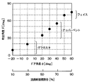
- the airflow blown out from the face outlet 43 is eroded by the upper and lower ambient air immediately after the blowout. In other words, the ambient air above and below the airflow blown from the face outlet 43 is involved. For this reason, as shown in FIG. 7, the airflow blown out from the face outlet 43 flows toward the rear of the vehicle while diffusing in the vertical direction.
- a portion of the airflow having a high blown air velocity is susceptible to erosion of the surrounding air, but in this embodiment, as shown in FIG. 8, in the vicinity of a high-speed airflow blown from the air outlet 11.
- the arrow in FIG. 8 has shown that the blowing wind speed is so high that it is long.
- a downward force along the upper surface 1a of the instrument panel 1 acts on the airflow. For this reason, the spreading
- a butterfly door 132 is employed as the airflow deflecting door 13.
- the butterfly door 132 includes a plate-like door main body and a rotation shaft provided at the center of the door main body.
- the vehicle front-rear direction length of the door main body is smaller than the width of the duct 12 in the vehicle front-rear direction. For this reason, even if the butterfly door 132 is leveled, the duct 12 is not closed.
- the rotation axis is located on the vehicle rear side with respect to the center of the duct 12 in the vehicle front-rear direction. This is because the cross-sectional area of the rear channel 12b is reduced to form a high-speed air flow in the rear channel 12b.
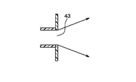
- FIG. 10 shows the result of the investigation of the relationship between the door angle ⁇ of the butterfly door 132 and the blowout angle ⁇ of the air blown from the blowout port 11 by the present inventor.
- the door angle ⁇ on the horizontal axis is an angle formed by the door main body with respect to the vertical direction, and the angle formed on the vehicle rear side with respect to the vertical direction is a positive value.
- the horizontal axis also shows the flow passage cross-sectional area ratio of the front flow passage 12a according to the door angle ⁇ .
- the remaining part obtained by subtracting the channel cross-sectional area ratio of the front-side channel 12a from 100% is the channel cross-sectional area ratio of the rear-side channel 12b.
- the vertical blowing angle ⁇ is an angle formed by the air blowing direction with respect to the vertical direction.
- the blowing angle ⁇ is increased.
- the flow passage cross-sectional area ratio of the front flow passage 12a is 10, 30%, and the blowing angle ⁇ is 10, 20 deg. Therefore, when the door angle ⁇ is approximately ⁇ 20 to 0 deg, it can be used as the defroster mode.
- the flow passage cross-sectional area ratio of the front flow passage 12a was 50, 60, and 70%, and the blowing angle ⁇ was 35, 45, and 55 deg. Therefore, the upper vent mode can be used when the door angle ⁇ is approximately 20 to 40 deg.
- the flow passage cross-sectional area ratio of the front flow passage 12a was 80, 90%
- the blowing angle ⁇ was 70, 75 deg. Therefore, it is possible to use the face mode when the door angle ⁇ is approximately 50 to 60 degrees.
- FIG. 10 shows the relationship between the door angle ⁇ and the blowout angle ⁇ when the butterfly door 132 is used, and the flow path cross-sectional area ratio when the slide door 131 of the first embodiment is used. It is estimated that the relationship with the blowing angle ⁇ is the same as that in FIG.
- the guide wall 14 is raised above the upper surface (general surface) 1 a of the instrument panel 1. For this reason, the uppermost part 14a of the guide wall 14 is located at a height h1 from the upper surface 1a of the instrument panel 1.
- the air flow from the air outlet 11 in the face mode is the same as that of the instrument panel 1. It flows close to the upper surface 1a.
- the face mode when cold air is blown out normally, if the upper surface 1a of the instrument panel 1 is heated by solar radiation, the cold air is heated by heat radiation from the upper surface 1a of the instrument panel 1.
- the uppermost portion 14a of the guide wall 14 is at a position higher than the upper surface 1a of the instrument panel 1, and the blown airflow from the air outlet 11 in the face mode is the uppermost portion of the guide wall 14. It flows substantially horizontally in the space above 14a. That is, according to this embodiment, the blown airflow from the blower outlet 11 in the face mode can be separated from the upper surface 1a of the instrument panel 1. Thereby, it can suppress that a cold wind is heated by the thermal radiation from the upper surface 1a of the instrument panel 1.
- the upper surface 1 a of the instrument panel 1 is inclined so as to become lower from the outlet 11 toward the vehicle rear side. Thereby, the uppermost part 14 a of the guide wall 14 is located at a position higher than the upper surface 1 a of the instrument panel 1. For this reason, also by this embodiment, the same effect as a 3rd embodiment is acquired.
- the upper surface 1a of the instrument panel 1 has a step portion 1c, and the upper surface 1a is raised by the step portion 1c.
- the uppermost part 14a of a guide wall exists in the position lower than the uppermost part of the step part 1c.
- a portion of the upper surface 1a on the vehicle front side with respect to the step portion 1c is at the same height as the uppermost portion 14a of the guide wall 14.
- a portion of the upper surface 1a on the vehicle rear side with respect to the step portion 1c is inclined so as to become lower toward the vehicle rear side.
- the height of the stepped portion 1c is set so that the blown airflow from the blowout port 11 in the face mode can exceed the stepped portion 1c. For this reason, in this embodiment, the blowing airflow from the blower outlet 11 at the time of face mode flows substantially horizontally, exceeding the step part 1c.
- the portion of the upper surface 1a on the vehicle rear side with respect to the stepped portion 1c is inclined so as to become lower toward the vehicle rear side, so that the air flow from the air outlet 11 in the face mode Can be separated from the upper surface 1 a of the instrument panel 1.
- the same effect as the third embodiment can be obtained.
- the upper surface 1a of the instrument panel 1 may be inclined so as to become lower toward the vehicle rear side.
- the airflow from the air outlet 11 in the face mode can be separated from the upper surface 1 a of the instrument panel 1.
- the upper surface 1a of the instrument panel 1 is a flat inclined surface.
- the upper surface 1a is not necessarily a flat inclined surface, and is provided with a stepped portion (unevenness). May be.
- it is only necessary that the upper surface 1a of the instrument panel 1 is lowered below the horizontal as it goes to the vehicle rear side. According to this, since the blowing airflow from the blower outlet 11 in the face mode flows substantially horizontally in the upper space of the upper surface 1a of the instrument panel 1, the blowing airflow can be separated from the upper surface 1a of the instrument panel 1. .
- a cantilever door 133 is employed as the airflow deflecting door 13.
- the cantilever door 133 includes a plate-like door main body and a rotating shaft provided at one end of the door main body.
- the vehicle front-rear direction length of the door main body is smaller than the width of the duct 12 in the vehicle front-rear direction. For this reason, even if the cantilever door 133 is leveled, the duct 12 is not closed. According to this embodiment, the same effect as that of the first embodiment can be obtained.
- a wall 15 is provided.
- two cantilever doors 134 and 135 are employed as the airflow deflecting door 13. The effect similar to 1st Embodiment is acquired by adjusting the flow-path cross-sectional area ratio of the front side flow path 12a and the back side flow path 12b with the two cantilever doors 134 and 135.
- the duct 12 can be fully closed, and the defroster / face door 34 can be omitted.
- two slide doors 136 and 137 are employed as the airflow deflecting door 13.
- the effect similar to 1st Embodiment is acquired by adjusting the flow-path cross-sectional area ratio of the front side flow path 12a and the back side flow path 12b with the two slide doors 136 and 137.
- the duct 12 can be fully closed, and the defroster / face door 34 can be omitted.
- a guide wall 142 having a tapered wall surface is employed as the guide wall 14.
- the taper shape is a flat surface shape that gradually increases the flow path width of the duct 12 toward the downstream side of the air flow.
- This guide wall 142 can also guide high-speed airflow along the wall surface to the vehicle rear side.
- a guide wall 143 having a stepped wall surface is employed as the guide wall 14.
- This guide wall 143 can also guide a high-speed air flow along the wall surface to the vehicle rear side.
- the guide wall is not limited to a curved shape, and the guide wall may be any shape that can bend a high-speed air current along the wall surface.
- the duct 12 is provided with a first guide wall 14 on the vehicle rear side wall of the air outlet 11 side portion and the vehicle front side of the air outlet 11 side portion.
- the second guide wall 16 is provided on the wall.
- the first guide wall 14 is the same as the guide wall 14 of the first embodiment.
- the second guide wall 16 is for guiding a high-speed air flow along the wall surface to the front side of the vehicle.
- the second guide wall 16 is different from the first guide wall 14 except that the first guide wall 14 is different in the front-rear direction. It has the same shape.
- the first and second guide walls 14 and 16 may have a tapered shape or a stepped shape as in the tenth and eleventh embodiments.
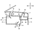
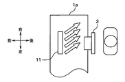
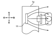
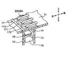
- the air outlet 11 has a shape that extends long in one direction, specifically in the left-right direction of the vehicle, and is arranged over the front of the driver seat and the front of the passenger seat where the steering 3 is located. Yes.
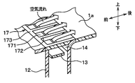
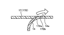
- the cover 17 is a foreign matter intrusion prevention member that prevents foreign matter from entering from the air outlet 11.
- the cover 17 is a slit forming member for forming a plurality of slits 171.
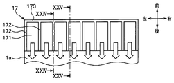
- the cover 17 has a comb shape, and includes a plurality of rod-like members 172 corresponding to a plurality of comb teeth, and a connecting member 173 that connects them.
- the plurality of rod-shaped members 172 are parallel to the vehicle front-rear direction, and the connecting member 173 is parallel to the vehicle left-right direction.
- a slit 171 is formed between adjacent rod-shaped members 172.
- the slit 171 is an opening that is long in one direction.
- the slit 171 extends parallel to the vehicle longitudinal direction. In other words, the slit 171 extends in a direction perpendicular to the direction in which the air outlet 11 extends long. For this reason, the slit 171 has a shape extending in parallel to the direction in which air is blown out from the air outlet 11 toward the occupant (see the white arrow in FIGS. 22 and 23) in the face mode.
- the bar-like member when the bar-like member is parallel to the left-right direction of the vehicle and the cover is provided with a slit parallel to the left-right direction of the vehicle, the bar-like member exists in the entire area of the left-right direction of the vehicle Therefore, it affects the direction of the air blown out from the air outlet 11 in the face mode. That is, when the high-speed airflow flows along the guide wall 14, the air flowing inside the duct 12 is bent toward the rear side of the vehicle and blown out from the air outlet 11. If it exists in the passing position, the high-speed air current flows along the rod-shaped member, so that the bending angle when the air current bends along the guide wall 14 becomes small.
- the slit 171 has a shape extending in parallel to the direction in which air is blown from the air outlet 11 toward the occupant, and the high-speed airflow passes through the slit 17.
- the width of the slit 171 is determined in consideration of the size of the foreign matter that prevents intrusion and the ventilation resistance when air passes through the slit 171.
- the extending direction of the slit 171 is the vehicle front-rear direction, but may be other directions.
- the extending direction of the slit 171 may be the direction.
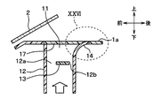
- the end 172 a of the rod-shaped member 172 of the cover 17 is in contact with the guide wall 14. Therefore, the end 172 a of the rod-shaped member 172 is a contact portion that contacts the guide wall 14.
- the uppermost portion 172 b of the contact portion 172 a of the rod-shaped member 172 is at the same height position as the uppermost portion 14 a of the guide wall 14.
- the uppermost portion 172b of the contact portion 172a of the rod-shaped member 172 is a downstream end portion of the contact portion 172a when the airflow along the guide wall 14 is formed, and the uppermost portion 14a of the guide wall 14 is connected to the guide wall 14. It is a downstream side edge part of the guide wall 14 when the airflow which follows is formed.
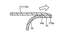
- the end portion 172a of the cover 17 may be changed to be positioned downstream of the uppermost portion 14a of the guide wall 14 as shown in FIG.
- the end 172a of the cover 17 is brought into contact with the upper surface 1a of the instrument panel instead of the guide wall 14.
- the cover 17 since the cover 17 exists on the downstream side when the airflow along the guide wall 14 is formed rather than the uppermost portion 14a of the guide wall 14, the air blown out from the outlet 11 in the face mode The cover 17 affects the direction.
- the uppermost portion 172b of the contact portion 172a of the rod-shaped member 172 is set at the same height position with respect to the uppermost portion 14a of the guide wall 14, so that the uppermost portion of the guide wall 14 None that affects the direction of air is present downstream of 14a. Thereby, the influence of the cover 17 given to the direction of the air blown out from the blower outlet 11 in the face mode can be reduced.
- the cover 17 has the rod-like member 172, but the rod-like member 172 may be changed to a plate-like member.
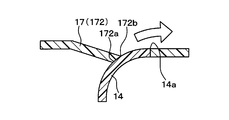
- the position of the contact portion 172a of the cover 17 is changed with respect to the thirteenth embodiment. Specifically, as shown in FIG. 28, the uppermost portion 172 b of the contact portion 172 a of the cover 17 is at a position lower than the uppermost portion 14 a of the guide wall 14.
- the uppermost portion 172b of the contact portion 172a of the cover 17 is located on the upstream side of the uppermost portion 14a of the guide wall 14, and affects the direction of air downstream of the uppermost portion 14a of the guide wall 14. Therefore, as in the thirteenth embodiment, the influence of the cover 17 on the direction of the air blown from the air outlet 11 in the face mode can be reduced.
- the cover 17 is disposed away from the guide wall 14. That is, the end 172 c of the rod-shaped member 172 of the cover 17 is not in contact with the guide wall 14, and a space is formed in the vicinity of the guide wall 14. According to this, since the cover 17 does not exist in the vicinity of the guide wall 14, the direction of the air blown out from the air outlet 11 in the face mode is not affected.
- cover 17 may exist above the uppermost portion 14 a of the guide wall 14 at a position away from the guide wall 14.
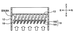
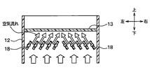
- a left-right adjustment door 18 is provided inside the duct 12.
- the left / right direction adjusting door 18 is a blow direction adjusting member that adjusts the air blowing direction from the air outlet 11 in the left / right direction of the vehicle by adjusting the direction of the air flow flowing in the duct 12 in the left / right direction of the vehicle.
- the left / right direction adjusting door 18 also has a wind speed of air blown from the central portion of the air outlet 11 and an air speed of air blown from a portion outside the central portion of the air outlet 11 in the left / right direction of the vehicle. It also functions as a wind speed distribution forming unit that forms a wind speed distribution that is different from each other.
- the left-right direction of the vehicle corresponds to a direction perpendicular to the direction connecting the other side and one side.
- the left / right direction adjusting door 18 is disposed on the upstream side of the air flow with respect to the airflow deflecting door 13 in the duct 12.
- the airflow deflecting door 13 is the same sliding door as in the first embodiment.
- the left-right direction adjustment door 18 is configured as a butterfly door having a plate-like door body 181 and a rotating shaft 182.
- the left and right direction adjusting doors 18 are plural and are arranged in parallel to the air flow.
- the plurality of left and right adjustment doors 18 all face the same direction, or as shown in FIGS. 35 and 36, the left and right groups of the plurality of left and right adjustment doors 18 It is possible to point in different directions. Therefore, by setting the direction of the plurality of left and right direction adjustment doors 18 to the direction shown in FIG. 34, air is blown out from the outlet 11 toward only one side in the left and right direction, or the direction shown in FIG. The air may be blown out in a V shape from the air outlet 11 toward both sides in the left-right direction, or the air may be blown out from the air outlet 11 in a central portion in the left-right direction by setting the orientation shown in FIG. it can.
- the air blown from the air outlet 11 can be passed through the side of the occupant's face by setting the direction shown in FIG. 35, or the air blown from the air outlet 11 can be changed to the direction shown in FIG. You can concentrate on the face of the passenger. Further, in the defroster mode, the air blown from the air outlet 11 can be spread over the front surface of the windshield 2 by switching between the direction shown in FIG. 35 and the direction shown in FIG. .
- the high-speed airflow formed by the airflow deflecting door 13 bends and flows along the guide wall 14 so that air is blown out from the air outlet 11 toward the occupant.
- the left-right direction adjustment door 18 is provided on the downstream side of the airflow of the airflow deflection door 13
- the high-speed airflow formed by the airflow deflection door 13 flows along the left-right direction adjustment door 18, The bending state of the air that bends and flows along the guide wall 14 is reduced.
- the left-right direction adjustment door 18 is provided on the upstream side of the airflow of the airflow deflection door 13, and before the high-speed airflow is formed by the airflow deflection door 13, the direction of the airflow in the left-right direction is adjusted. Yes. For this reason, since the high-speed airflow formed by the airflow deflecting door 13 bends and flows along the guide wall 14, it can be avoided that the bending state of the air that bends and flows along the guide wall 14 becomes small.
- the left-right adjustment door 18 is configured as a butterfly door, but may be configured as a cantilever door having a door body and a rotation shaft.
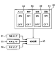
- the operation panel 60 is provided with selection switches 61, 62, 63, and 64 for each wind direction mode of the avoidance mode, the diffusion mode, the concentration mode, and the auto mode. Operation signals from the selection switches 61 to 64 for each wind direction mode are input to the control device 50. Based on the input operation signal, the control device 50 operates the plurality of left and right direction adjusting doors 18 so that the selected wind direction mode is executed. In this way, the occupant can manually change the wind direction mode by operating the selection switch.
- the control device 50 is composed of a microcomputer and its peripheral circuits, and controls the operation of various devices connected to the output side.
- the operation panel 60 is provided with various air conditioning operation switches such as a vehicle interior temperature setting switch for setting the vehicle interior temperature, in addition to the selection switches 61 to 64 for each wind direction mode, and operation signals from the various air conditioning operation switches are received. It is input to the control device 50.
- the control device 50 receives detection signals from sensor groups such as an inside air sensor 51 that detects the vehicle interior temperature Tr, an outside air sensor 52 that detects the outside air temperature Tam, and a solar radiation sensor 53 that detects the amount of solar radiation Ts in the vehicle interior. It has come to be.
- the air outlet 11 is provided corresponding to the driver's seat and the passenger seat. Below, the blower outlet 11 corresponding to a driver's seat is demonstrated.
- the blower outlet 11 has the same center position in the left-right direction as the center position in the left-right direction of the seat, and the length of the blower outlet 11 in the left-right direction is the same as the left and right length of the seat.
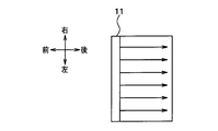
- the normal mode is when the selection switches 61 to 64 for each wind direction mode are all OFF. As shown in FIG. 38, this normal mode is directed from the air outlet 11 toward the occupant in the air outlet mode in which air is blown out from the air outlet 11 toward the rear of the vehicle, for example, as in the face mode or the bi-level mode. Blow out the air.
- the plurality of left and right adjustment doors 18 are all parallel to the vertical direction.
- the wind speed distribution of the air blown from the outlet 11 is a distribution in which the wind speed is uniform in the left-right direction.
- the wind speed distribution at the position of the occupant is the highest wind speed distribution at the position of the occupant's face (particularly around the mouth).
- FIG. 41 shows the wind speed distribution in the occupant's face and the surrounding area, and the curve in FIG. 41 is a boundary line that partitions the same wind speed area.
- this avoidance mode is the direction of the blown air from the blowout port 11 in the blowout mode in which air is blown out from the blowout port 11 toward the rear of the vehicle, as in the face mode or the bi-level mode. This is a wind direction mode in which the occupant is avoided.
- the plurality of left and right direction adjusting doors 18 are all tilted so that the downstream end is on the window side (right side in the case of a right-hand drive vehicle). Thereby, the air which passed the some left-right direction adjustment door 18 flows toward the vehicle right side. Then, while maintaining the direction of the air flow, the air flow bends to the vehicle rear side along the guide wall 14, and as shown in FIG. 42, the vehicle rearward from the air outlet 11 and on the right side of the vehicle from the occupant. Air is blown out. When no passenger is present in the passenger seat, air may be blown out from the air outlet 11 toward the passenger seat only.
- the avoidance mode is selected when the occupant wants to avoid direct wind hitting the occupant. For example, when the occupant selects this avoidance mode at the start of cool-down in summer, the heat mass in the ventilation path (the amount of heat existing in the ventilation path) can be discarded without directing the occupant. In addition, when the occupant selects this avoidance mode during the cooling operation, it is possible to prevent the conditioned air from directly hitting the occupant.
- This avoidance mode is also selected when it is desired to blow conditioned air toward the window side from the passenger. For example, when the temperature of the window side portion in the vehicle interior is higher than that of other spaces due to partial solar radiation, by selecting this avoidance mode, cold air can be blown to the window side portion of the vehicle interior.
- the diffusion mode selection switch 62 When the diffusion mode selection switch 62 is ON, the diffusion mode is set.
- the diffusion mode is a blow mode in which air is blown out toward the rear of the vehicle from the blowout port 11 as in the face mode or the bi-level mode. It is a wind direction mode that diffuses widely in the direction.
- the downstream end of the left and right side adjusting door 18 is directed to the left side of the vehicle, and the right and left side adjusting doors are adjusted.
- the downstream end of the door 18 is directed to the right side of the vehicle.
- the wind speed distribution of the blown air from the blower outlet 11 is such that the wind speed of the blown air from the central part in the left-right direction is low and the wind speed of the blown air from the outside is higher than the central part. Wind speed distribution. For this reason, for example, when the occupant selects this diffusion mode during the cooling operation, a gentle breeze close to natural wind can be directly given to the occupant as shown in FIG. Note that the wind speed distribution shown in FIG. 45 is smaller in the number of boundary lines in the occupant's face and the surrounding area than the wind speed distribution in the normal mode shown in FIG. It is small. In addition, the wind speed at the position of the occupant's face is lower than that in the normal mode under the same conditions of the blower's blowing capacity.
- the diffusion mode of the present embodiment the air blown from the air outlet 11 is directly applied to the occupant, so that the occupant can be directly cooled by the blown air.
- the diffusion mode of the present embodiment it is possible to reduce the capacity and power of the compressor constituting the refrigeration cycle as compared with the indirect air conditioning in the conventional example.
- the left and right side walls of the duct 12 are parallel to the vehicle vertical direction. For this reason, some of the air that has passed through the plurality of left and right direction adjusting doors 18 flows along the left and right side walls of the duct 12. Accordingly, as shown in FIG. 43, the air blown from the air outlet 11 flows in a V shape toward the outer side in the left-right direction, and then forms an air flow that bends inward in the left-right direction and envelops the occupant. This has been confirmed by the inventors' experiments.
- the duct 12 is arranged such that the distance between the left and right side walls of the duct 12 increases toward the downstream side of the air flow on the downstream side of the air flow adjustment door 18 of the duct 12.
- the 12 shapes may be changed.
- air is blown out from the blower outlet 11 so as to spread in a V shape on both the left and right sides. Even in this case, a wind speed distribution as shown in FIGS. 44 and 45 is formed.
- the diffusion mode can be used, for example, when the heat mass in the ventilation path is discarded at the start of cooldown in summer. Further, by using the diffusion mode in the defroster mode, the windshield fog can be cleared over a wide range.
- the central mode selection switch 63 When the central mode selection switch 63 is ON, the central mode is selected.
- the concentration mode is a mode in which air is blown from the air outlet 11 when the air is blown out from the air outlet 11 toward the rear of the vehicle as in the face mode or the bi-level mode. It is a wind direction mode that concentrates on a part of the seat.
- a part of the driver's seat is, for example, a central portion in the left-right direction of the driver's seat.
- the plurality of left and right direction adjusting doors 18 When the concentrated mode is selected, as shown in FIG. 36, the plurality of left and right direction adjusting doors 18 have the downstream end of the left and right side adjusting door 18 facing the right side of the vehicle and the right and left side adjusting doors. The downstream end of the door 18 is directed to the left side of the vehicle. Thereby, the air which passed the some left-right direction adjustment door 18 flows in reverse V shape. Then, while maintaining the direction of the air flow, the air flow bends to the vehicle rear side along the guide wall 14, and as shown in FIG. 48, while concentrating on the left and right inner sides from the air outlet 11 toward the vehicle rear. Air is blown out.
- the wind speed distribution of the blown air from the blower outlet 11 indicates that the wind speed of the blown air from the central part in the left-right direction is high and the wind speed of the blown air from the outside is lower than the central part. Wind speed distribution. Therefore, for example, when the occupant selects this concentrated mode during the cooling operation, cold air can be given to the occupant in a spot manner as shown in FIG.
- the wind speed distribution shown in FIG. 50 has the highest wind speed at the position of the occupant's face. Compared with the wind speed distribution in the normal mode shown in FIG. In many cases, there is a large difference in wind speed between the occupant's face and the surrounding area.
- the airflow blown from the blower outlet 11 includes the surrounding air on the left and right. For this reason, the cold wind blown out from the blower outlet 11 is easily influenced by the temperature of the surrounding air, and the temperature of the cold wind reaching the passenger increases.
- the high-speed airflow from the central part of the blower outlet 11 is from outside the central part of the blower outlet 11.
- a low-speed air current is involved, and the amount of ambient air can be reduced.
- the influence of the surrounding air with respect to the cold wind blown out from the blower outlet 11 can be suppressed, and the temperature rise of the cold wind reaching the passenger can be suppressed.
- the cooling punching power can be increased during the cool-down period in summer.
- the concentration mode can be intensively cleared by selecting it in the defroster mode. At this time, the direction of the left-right adjustment door 18 is finely adjusted manually by the occupant, or the control device 50 automatically finely adjusts the position of the portion of the windshield where the blown air is concentrated. You may do it.
- the control device 50 selects any one of the avoidance mode, the diffusion mode, the concentration mode, and the normal mode as the wind direction mode.
- the control device 50 calculates the target blown air temperature TAO based on the vehicle interior temperature, the inside air temperature, the outside air temperature, and the like set by the occupant, and determines the operating states of various devices according to the target blown air temperature TAO.
- the avoidance mode is selected at the rise of the cool-down, the concentrated mode is selected after the rise of the cool-down, and the diffusion mode is selected during steady operation after the cool-down.
- the heat mass in the ventilation path can be thrown away without directing it toward the occupant at the start of cooldown, and cold air can be spotted on the occupant after the start of cooldown. A gentle breeze close to the natural wind can be applied to the passenger.
- the rise of the cool-down is a predetermined period from the start of the cool-down control in the cooling operation until the blown wind becomes cool.
- the term “after the start of cool-down” refers to the period from the start of the cool-down control in the cooling operation to the end of the cool-down control after the elapse of a predetermined period from when the blown air becomes cool.
- the steady operation is a cooling operation after the end of the cool-down control, for example, when the difference between the target blown air temperature TAO and the inside air temperature is smaller than a predetermined temperature.
- control device 50 may select the avoidance mode so that air blows out from the air outlet 11 toward the window side.
- the present embodiment is different from the sixteenth embodiment in that the airflow deflecting door 13 is a butterfly door 132 having a door body portion and a rotating shaft. Further, in the present embodiment, a recess 183 is formed on one side of the door main body 181 of the left-right adjustment door 18 on the airflow deflection door 13 side. The recess 183 is formed so that the airflow deflecting door 13 does not hit when the airflow deflecting door 13 rotates, and the locus drawn by the end of the airflow deflecting door 13 when the airflow deflecting door 13 rotates. It is the circular arc shape along.
- the airflow deflection door 13 and the left-right direction adjustment door 18 have a positional relationship in which the end of the airflow deflection door 13 passes through the recess 183 of the left-right direction adjustment door 18 when the airflow deflection door 13 rotates.
- the distance between the airflow deflection door 13 and the left-right adjustment door 18 can be shortened, and the duct 12 can be downsized (shortened).
- the concave portion 183 has an arc shape, but is not limited to this shape, and may have another shape such as a square.
- the left-right direction adjustment door 18 is configured as a butterfly door, but the left-right direction adjustment door 18 may be configured as a cantilever door having a door body portion and a rotation shaft.
- the rotation shaft is positioned at the upstream end of the door body, and a recess is formed on one side of the door body on the side of the air flow deflecting door 13.
- the duct 12 has a bent portion 121 on the upstream side of the air flow of the air outlet 11, and a plurality of left and right direction adjusting doors 18 are provided inside the bent portion 121. ing.
- the bent portion 121 of the duct 12 is bent so that the outside (right side in the figure) is convex so as to guide the air flowing in the left-right direction (right direction in the figure) upward.
- the passage cross-sectional area of the duct 12 is narrowed upstream of the bent portion 121 so that the air volume after passing through the bent portion 121 is uniform in the left-right direction.
- the left-right direction adjustment door 18 is a butterfly door, and has a curved shape so that the door main body 181 is convex on the same side as the bent portion 121 of the duct 12.
- the plurality of left and right direction adjustment doors 18 have the same size of the door body 181.
- the plurality of left and right adjustment doors 18 are configured to be rotatable so that they all face the same direction.
- the bending of the duct 12 is performed. It is possible to make the wind passing through the section 121 uniform in the left-right direction.
- the shape of the door main body portion 181 of the left-right adjustment door 18 is curved so that the same side as the bent portion 121 is convex.
- the wind passing outside the door main body 181 peels off from the door main body 181, thereby causing pressure loss and generating sound.
- the cross-sectional area of the flow path upstream of the bent portion 121 is uniform in the air flow direction.
- the door main-body part 181 of the some left-right direction adjustment door 18 is large toward the outer side of the bending part 121.
- a plurality of air passages are defined in the bent portion 121 by the plurality of right and left direction adjusting doors 18, and the air passage becomes longer and the pressure loss increases toward the outside of the bent portion 121. As a result, it is possible to make the wind passing through the bent portion 121 uniform in the left-right direction.
- the left-right adjustment door 18 is configured as a butterfly door, but may be configured as a cantilever door having a door body and a rotation shaft.
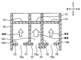
- partition walls 71 and 72 are provided to partition the inside of the duct 12 into three passages 12c, 12d, and 12e arranged in the left-right direction.
- the partition walls 71 and 72 are provided over the air flow upstream and downstream sides of the airflow deflecting door 13.
- the partition walls 71 and 72 are disposed such that the passage cross-sectional area of the central passage 12c is small and the passage cross-sectional areas of the left passage 12d and the right passage 12e are large.
- a wall 73 having an opening 73a is provided on the entrance side of each passage 12c, 12d, 12e.
- the opening areas of the openings 73a in the passages 12c, 12d, and 12e are all the same, and are smaller than the opening area of the central passage 12c.
- an adjustment door 74 for adjusting the opening area of the opening 73a is provided on the entrance side of the central passage 12c.
- the adjustment door 74 is a slide door.
- the partition walls 71 and 72, the wall 73 having the opening 73 a, and the adjustment door 74 are the wind speed of the air blown from the center of the air outlet 11 and the air outlet 11 in the vehicle left-right direction.
- a wind speed distribution forming section is formed that forms a wind speed distribution in which the wind speed of air blown from a portion outside the central portion is different. For this reason, also in this embodiment, the concentrated mode and the diffusion mode can be realized as in the sixteenth embodiment.
- the position of the adjustment door 74 is set to the fully open position of the opening 73a.
- the airflow in the central passage 12c becomes high speed
- the airflow in the left passage 12d and the right passage 12e becomes low speed.
- the wind speed distribution of the blown air from the blower outlet 11 becomes a wind speed distribution in which the wind speed of the blown air from the central part in the left-right direction is high and the wind speed of the blown air from the outside of the central part is low, and the concentrated mode is realizable.
- the position of the adjustment door 74 is a position where the opening area of the opening 73a is narrowed.
- the air volume in the central passage 12c is smaller than the air volume in the left passage 12d and the right passage 12e, the air flow in the central passage 12c becomes low, and the air flow in the left passage 12d and right passage 12e becomes high.
- the wind speed distribution of the blown air from the blower outlet 11 becomes a wind speed distribution in which the wind speed of the blown air from the central part in the left-right direction is low and the wind speed of the blown air from the outside of the central part is high, and the diffusion mode is realizable.
- the air blowing apparatus of this indication was applied to the blower outlet 11 of the upper surface 1a of the instrument panel 1, the air blower of this indication is applied to the blower outlet (foot outlet) of the lower surface of the instrument panel 1. You may apply to. In this case, the blowing angle of the air blown from the foot outlet can be arbitrarily changed.
- the air blowing apparatus of this indication was applied to the vehicle air conditioner, you may apply the air blowing apparatus of this indication to air conditioners other than a vehicle.
- the twelfth embodiment can be combined with each of the first to eleventh embodiments.
- the thirteenth embodiment can be combined with each of the first to twelfth embodiments.
- Each of the sixteenth to twentieth embodiments can be combined with each of the first to fifteenth embodiments.
- the cover 17 of the thirteenth embodiment and the left-right direction adjusting door 18 of the sixteenth embodiment can be used in combination.
Landscapes
- Engineering & Computer Science (AREA)
- Mechanical Engineering (AREA)
- Physics & Mathematics (AREA)
- Thermal Sciences (AREA)
- Air-Conditioning For Vehicles (AREA)
Abstract
Description
本実施形態では、本開示に係る空気吹出装置を車両前方に搭載される空調ユニットの吹出口およびダクトに適用している。 (First embodiment)
In the present embodiment, the air blowing device according to the present disclosure is applied to an air outlet and a duct of an air conditioning unit mounted in front of the vehicle.
本実施形態は、図9に示すように、気流偏向ドア13としてバタフライドア132を採用している。バタフライドア132は、板状のドア本体部と、ドア本体部の中心部に設けられた回転軸とを備える。ドア本体部の車両前後方向長さは、車両前後方向におけるダクト12の幅よりも小さい。このため、バタフライドア132を水平にしてもダクト12は閉じられない。回転軸は、ダクト12の車両前後方向での中心よりも車両後方側に位置する。これは、後方側流路12bの流路断面積を小さくして、後方側流路12bに高速の気流を形成するためである。 (Second Embodiment)
In this embodiment, as shown in FIG. 9, a
本実施形態では、図11に示すように、ガイド壁14がインストルメントパネル1の上面(一般面)1aよりも盛り上がっている。このため、ガイド壁14の最上部14aがインストルメントパネル1の上面1aから高さh1の位置にある。 (Third embodiment)
In this embodiment, as shown in FIG. 11, the
本実施形態では、図12に示すように、インストルメントパネル1の上面1aが吹出口11から車両後方側に向かうにつれて低くなるように傾斜している。これにより、ガイド壁14の最上部14aがインストルメントパネル1の上面1aよりも高い位置にある。このため、本実施形態によっても、第3実施形態と同様の効果が得られる。 (Fourth embodiment)
In the present embodiment, as shown in FIG. 12, the
本実施形態では、図13に示すように、インストルメントパネル1の上面1aが段部1cを有しており、この段部1cによって上面1aが盛り上がっている。このため、ガイド壁の最上部14aは、段部1cの最上部よりも低い位置にある。上面1aのうち段部1cよりも車両前方側の部位は、ガイド壁14の最上部14aと同じ高さ位置にある。一方、上面1aのうち段部1cよりも車両後方側の部位は、車両後方側に向かうにつれて低くなるように傾斜している。段部1cの高さは、フェイスモード時の吹出口11からの吹出気流が段部1cを越えられるように設定される。このため、本実施形態では、フェイスモード時の吹出口11からの吹出気流は、段部1cを越えながら略水平に流れる。 (Fifth embodiment)
In this embodiment, as shown in FIG. 13, the
本実施形態では、図14に示すように、気流偏向ドア13として、片持ちドア133を採用している。片持ちドア133は、板状のドア本体部と、ドア本体部の片側端部に設けられた回転軸とを備える。ドア本体部の車両前後方向長さは、車両前後方向におけるダクト12の幅よりも小さい。このため、片持ちドア133を水平にしてもダクト12は閉じられない。本実施形態によっても、第1実施形態と同様の効果が得られる。 (Sixth embodiment)
In the present embodiment, as shown in FIG. 14, a
本実施形態では、図15に示すように、ダクト12の内部のうち気流偏向ドア13の空気流れ下流側に、前方側流路12aに連なる流路と後方側流路12bに連なる流路とに仕切る仕切壁15を設けている。本実施形態によっても、第1実施形態と同様の効果が得られる。 (Seventh embodiment)
In this embodiment, as shown in FIG. 15, in the
本実施形態では、図16に示すように、ダクト12の内部のうち気流偏向ドア13の空気流れ下流側に、前方側流路12aに連なる通路と後方側流路12bに連なる通路とに仕切る仕切壁15を設けている。さらに、気流偏向ドア13として、2つの片持ちドア134、135を採用している。2つの片持ちドア134、135によって、前方側流路12aと後方側流路12bの流路断面積割合を調整することにより、第1実施形態と同様の効果が得られる。さらに、本実施形態によれば、2つの片持ちドア134、135を用いることで、ダクト12を全閉することが可能となり、デフロスタ/フェイスドア34を省略することができる。 (Eighth embodiment)
In the present embodiment, as shown in FIG. 16, a partition that divides the
本実施形態では、図17に示すように、気流偏向ドア13として、2枚のスライドドア136、137を採用している。2枚のスライドドア136、137によって、前方側流路12aと後方側流路12bの流路断面積割合を調整することにより、第1実施形態と同様の効果が得られる。さらに、本実施形態によれば、2枚のスライドドア136を用いることで、ダクト12を全閉することが可能となり、デフロスタ/フェイスドア34を省略することができる。 (Ninth embodiment)
In the present embodiment, as shown in FIG. 17, two
本実施形態では、図18に示すように、ガイド壁14として、壁面がテーパ形状であるガイド壁142を採用している。テーパ形状とは、ダクト12の流路幅を空気流れ下流側に向かって徐々に拡大させる平坦面形状である。このガイド壁142によっても、高速の気流を壁面に沿わせて車両後方側にガイドすることができる。 (10th Embodiment)
In this embodiment, as shown in FIG. 18, a
本実施形態では、図19に示すように、ガイド壁14として、壁面が段部を有する形状であるガイド壁143を採用している。このガイド壁143によっても、高速の気流を壁面に沿わせて車両後方側にガイドすることができる。本実施形態および第10実施形態のように、ガイド壁は湾曲した形状に限らず、ガイド壁は高速の気流を壁面に沿わせて曲げることができる形状であれば良い。 (Eleventh embodiment)
In this embodiment, as shown in FIG. 19, a guide wall 143 having a stepped wall surface is employed as the
本実施形態では、図20に示すように、ダクト12は、吹出口11側部分の車両後方側の壁に、第1ガイド壁14が設けられているとともに、吹出口11側部分の車両前方側の壁に、第2ガイド壁16が設けられている。第1ガイド壁14は、第1実施形態のガイド壁14と同じものである。第2ガイド壁16は、高速の気流を壁面に沿わせて車両前方側にガイドするためのものであり、第1ガイド壁14と前後方向の向きが異なる点を除き、第1ガイド壁14と同様の形状のものである。 (Twelfth embodiment)
In the present embodiment, as shown in FIG. 20, the
本実施形態では、図21に示すように、吹出口11にカバー17を設けている。吹出口11は、第1実施形態と同様に、一方向、具体的には、車両左右方向に長く延びた形状であり、ステアリング3が位置する運転席の正面および助手席の正面にわたって配置されている。カバー17は、吹出口11からの異物の侵入を防止する異物侵入防止部材である。 (13th Embodiment)
In the present embodiment, as shown in FIG. As with the first embodiment, the
本実施形態は、第13実施形態に対して、カバー17の接触部172aの位置を変更したものである。具体的には、図28に示すように、カバー17の接触部172aの最上部172bは、ガイド壁14の最上部14aよりも低い位置にある。 (14th Embodiment)
In the present embodiment, the position of the
本実施形態では、図29~31に示すように、カバー17がガイド壁14から離れて配置されている。すなわち、カバー17の棒状部材172の端部172cがガイド壁14に接触しておらず、ガイド壁14の近傍には空間が形成されている。これによれば、ガイド壁14の近傍にカバー17が存在しないので、フェイスモード時に吹出口11から吹出される空気の向きに影響を与えることがない。 (Fifteenth embodiment)
In the present embodiment, as shown in FIGS. 29 to 31, the
本実施形態では、図32~36に示すように、ダクト12の内部に左右方向調整ドア18が設けられている。この左右方向調整ドア18は、ダクト12の内部を流れる気流の車両左右方向の向きを調整することで、吹出口11からの空気吹出方向を、車両左右方向で調整する吹出方向調整部材である。また、左右方向調整ドア18は、車両左右方向において、吹出口11のうち中央部から吹き出される空気の風速と、吹出口11のうち中央部よりも外側の部分から吹き出される空気の風速とが異なるという風速分布を形成する風速分布形成部としても機能する。なお、車両左右方向が、他側と一側を結ぶ方向に対して垂直な方向に相当する。 (Sixteenth embodiment)
In this embodiment, as shown in FIGS. 32 to 36, a left-
本実施形態は、図51に示すように、気流偏向ドア13が、ドア本体部と回転軸を有するバタフライドア132である点が第16実施形態と異なっている。さらに、本実施形態では、左右方向調整ドア18のドア本体部181の気流偏向ドア13側の一辺に凹部183が形成されている。この凹部183は、気流偏向ドア13が回転したときに、気流偏向ドア13が当たらないように形成されたものであり、気流偏向ドア13が回転したときの気流偏向ドア13の端部が描く軌跡に沿った円弧形状である。 (17th Embodiment)
As shown in FIG. 51, the present embodiment is different from the sixteenth embodiment in that the
本実施形態では、図52に示すように、ダクト12が吹出口11の空気流れ上流側に曲がり部121を有しており、この曲がり部121の内部に複数の左右方向調整ドア18が設けられている。 (Eighteenth embodiment)
In the present embodiment, as shown in FIG. 52, the
本実施形態は、図53に示すように、ダクト12の曲がり部121に設けられた複数の左右方向調整ドア18の形状が、曲がり部121の外側ほど大きくなっている点が、第18実施形態と異なっている。 (Nineteenth embodiment)
In the present embodiment, as shown in FIG. 53, the shape of the plurality of left and right
本実施形態では、図54、55に示すように、ダクト12の内部を左右方向に並ぶ3つの通路12c、12d、12eに仕切る仕切壁71、72を設けている。この仕切壁71、72は、気流偏向ドア13の空気流れ上流側および下流側にわたって設けられている。仕切壁71、72は、中央通路12cの通路断面積が小さく、左側通路12dおよび右側通路12eの通路断面積が大きくなるように配置されている。 (20th embodiment)
In the present embodiment, as shown in FIGS. 54 and 55,
本開示は上記した実施形態に限定されるものではなく、下記のように、特許請求の範囲に記載した範囲内において適宜変更が可能である。 (Other embodiments)
The present disclosure is not limited to the above-described embodiment, and can be appropriately changed within the scope described in the claims as follows.
Claims (20)
- 対象空間に空気を吹き出す吹出口(11)と、
前記吹出口に連なり、内部に空気流路が形成されるダクト(12)と、
前記ダクトの内部に設けられた気流偏向部材(13)とを備え、
前記ダクトの内部における前記気流偏向部材を挟んだ一側と他側の空気流路をそれぞれ一側流路(12b)と他側流路(12a)とし、
前記気流偏向部材は、前記一側流路の流路断面積割合を前記他側流路の流路断面積割合よりも小さくすることにより、前記一側流路に高速の気流を形成するとともに、前記他側流路に低速の気流を形成する第1状態と、前記ダクトの内部に前記第1状態とは異なる気流を形成する第2状態とを切り替え可能に構成されており、
前記ダクトは、前記吹出口側部分における前記一側の壁に、前記一側流路からの高速の気流を壁面に沿わせて曲げるガイド壁(14)が設けられている空気吹出装置。 An air outlet (11) for blowing air into the target space;
A duct (12) connected to the air outlet and having an air flow path formed therein;
An airflow deflecting member (13) provided inside the duct,
One side flow path and the other side flow path (12b) and the other side flow path (12a) sandwiching the air flow deflecting member inside the duct, respectively,
The airflow deflecting member forms a high-speed airflow in the one-side flow path by making the flow-path cross-sectional area ratio of the one-side flow path smaller than that of the other-side flow path, A first state in which a low-speed airflow is formed in the other-side flow path and a second state in which an airflow different from the first state is formed in the duct, are configured to be switchable,
The duct is an air blowing device in which a guide wall (14) for bending a high-speed airflow from the one-side flow path along a wall surface is provided on the one-side wall in the outlet side portion. - 前記気流偏向部材は、前記第1状態における前記一側流路の流路断面積と前記他側流路の流路断面積の割合を変更することにより、高速の気流と低速の気流の速度比を調整可能に構成されている請求項1に記載の空気吹出装置。 The airflow deflecting member is configured to change a ratio of a channel cross-sectional area of the one-side channel and a channel cross-sectional area of the other-side channel in the first state, so that a speed ratio between a high-speed airflow and a low-speed airflow The air blowing device according to claim 1, which is configured to be adjustable.
- 前記ダクトの内部に設けられ、前記他側と前記一側を結ぶ方向に対して垂直な方向において、前記吹出口のうち中央部から吹き出される空気の風速と、前記吹出口のうち前記中央部よりも外側から吹き出される空気の風速とが異なるという風速分布を形成する風速分布形成部(18、71、72、73、74)を備える請求項1または2に記載の空気吹出装置。 In the direction perpendicular to the direction connecting the other side and the one side provided in the duct, the wind speed of the air blown out from the central portion of the outlet, and the central portion of the outlet The air blowing device according to claim 1 or 2, further comprising a wind speed distribution forming part (18, 71, 72, 73, 74) that forms a wind speed distribution that is different from a wind speed of air blown from outside.
- 前記ダクトの内部に設けられ、前記吹出口からの空気吹出方向を、前記他側と前記一側を結ぶ方向に対して垂直な方向で調整する板状の吹出方向調整部材(18)を複数備え、
前記吹出方向調整部材は、前記気流偏向部材よりも上流側に配置されている請求項1または2に記載の空気吹出装置。 A plurality of plate-like blowing direction adjusting members (18) provided inside the duct and for adjusting an air blowing direction from the blowing outlet in a direction perpendicular to a direction connecting the other side and the one side. ,
The air blowing device according to claim 1, wherein the blowing direction adjusting member is disposed upstream of the airflow deflecting member. - 前記吹出方向調整部材は、前記吹出口のうち前記他側と前記一側を結ぶ方向に対して垂直な方向における中央部からの吹出空気の風速が低く、前記中央部よりも外側からの吹出空気の風速が高いという風速分布を形成できるように構成されている請求項4に記載の空気吹出装置。 The blowing direction adjusting member has a low wind speed from the central portion in a direction perpendicular to the direction connecting the other side and the one side of the outlet, and the blowing air from outside the central portion. The air blowing device according to claim 4, wherein the air blowing device is configured to be able to form a wind speed distribution in which the wind speed is high.
- 前記吹出方向調整部材は、前記ダクトの内部において、前記吹出方向調整部材を通過した空気の流れをV字状とすることができるように構成されている請求項5に記載の空気吹出装置。 6. The air blowing device according to claim 5, wherein the blowing direction adjusting member is configured so that the flow of air that has passed through the blowing direction adjusting member can be V-shaped inside the duct.
- 前記吹出方向調整部材は、前記吹出口のうち前記他側と前記一側を結ぶ方向に対して垂直な方向における中央部からの吹出空気の風速が高く、前記中央部よりも外側からの吹出空気の風速が低いという風速分布を形成できるように構成されている請求項4ないし6のいずれか1つに記載の空気吹出装置。 The blowing direction adjusting member has a high air velocity from the central portion in a direction perpendicular to the direction connecting the other side and the one side of the outlet, and the blowing air from outside the central portion. The air blowing device according to any one of claims 4 to 6, wherein the air blowing device is configured to form a wind speed distribution in which the wind speed is low.
- 前記吹出方向調整部材は、前記ダクトの内部において、前記吹出方向調整部材を通過した空気の流れを逆V字状とすることができるように構成されている請求項7に記載の空気吹出装置。 The air blowing device according to claim 7, wherein the blowing direction adjusting member is configured so that the flow of air that has passed through the blowing direction adjusting member can be formed in an inverted V shape inside the duct.
- 前記気流偏向部材は、前記一側と前記他側にスライド可能なスライドドア(131)である請求項1ないし8のいずれか1つに記載の空気吹出装置。 The air blowing device according to any one of claims 1 to 8, wherein the airflow deflecting member is a sliding door (131) slidable on the one side and the other side.
- 前記気流偏向部材は、バタフライドア(132)である請求項1ないし8のいずれか1つに記載の空気吹出装置。 The air blowing device according to any one of claims 1 to 8, wherein the airflow deflecting member is a butterfly door (132).
- 前記気流偏向部材は、ドア本体部と回転軸を有するバタフライドア(132)であり、
前記吹出方向調整部材は、ドア本体部(181)と回転軸(182)を有するバタフライドアもしくは片持ちドアであり、
前記吹出方向調整部材は、前記ドア本体部の前記気流偏向部材側の一辺に凹部(183)が形成されており、
前記気流偏向部材および前記吹出方向調整部材は、前記気流偏向部材が回転する際に、前記気流偏向部材が前記凹部内を通過する位置関係を有する請求項4ないし8のいずれか1つに記載の空気吹出装置。 The airflow deflecting member is a butterfly door (132) having a door body and a rotating shaft,
The blowing direction adjusting member is a butterfly door or a cantilever door having a door body portion (181) and a rotating shaft (182),
The blowing direction adjusting member has a recess (183) formed on one side of the door body portion on the airflow deflecting member side,
9. The air flow deflecting member and the blowing direction adjusting member have a positional relationship in which the air flow deflecting member passes through the recess when the air flow deflecting member rotates. Air blowing device. - 前記ダクトは、凸状に曲がる曲がり部(121)を有しており、
前記吹出方向調整部材は、ドア本体部と回転軸を有するバタフライドアもしくは片持ちドアであるとともに、前記曲がり部に設けられており、
前記吹出方向調整部材のドア本体部は、前記曲がり部と同じ側が凸状となるように湾曲した形状である請求項4ないし8のいずれか1つに記載の空気吹出装置。 The duct has a bent portion (121) that bends in a convex shape,
The blowing direction adjusting member is a butterfly door or a cantilever door having a door main body and a rotating shaft, and is provided in the bent portion.
The air blowing device according to any one of claims 4 to 8, wherein the door main body portion of the blowing direction adjusting member has a curved shape so that the same side as the bent portion is convex. - 前記吹出口に設けられ、複数のスリット(171)が形成されたスリット形成部材(17)を備え、
前記スリットは、前記気流偏向部材が前記第1状態としたときに前記吹出口から乗員に向かって空気が吹出される方向に対して平行に延びた形状である請求項1ないし12のいずれか1つに記載の空気吹出装置。 A slit forming member (17) provided at the air outlet and formed with a plurality of slits (171),
The slit is in a shape extending in parallel with a direction in which air is blown out from the air outlet toward an occupant when the airflow deflecting member is in the first state. The air blowing device according to one. - 前記スリット形成部材は、前記ガイド壁に接触する接触部(172a)を有し、
前記ガイド壁に沿う気流が形成されるときの前記接触部の下流側端部(172b)は、前記ガイド壁の下流側端部(14a)に対して、同じ位置もしくはそれよりも上流側の位置にある請求項13に記載の空気吹出装置。 The slit forming member has a contact portion (172a) that contacts the guide wall,
The downstream end (172b) of the contact portion when the airflow along the guide wall is formed is the same position or a position upstream from the downstream end (14a) of the guide wall. The air blowing device according to claim 13. - 前記スリット形成部材は、前記ガイド壁から離れている請求項13に記載の空気吹出装置。 The air blowing device according to claim 13, wherein the slit forming member is separated from the guide wall.
- 前記吹出口は、車両のインストルメントパネルの上面(1a)に設けられ、
前記一側と前記他側は、それぞれ、車両後方側と車両前方側である請求項1ないし15のいずれか1つに記載の空気吹出装置。 The air outlet is provided on the upper surface (1a) of the instrument panel of the vehicle,
The air blowing device according to any one of claims 1 to 15, wherein the one side and the other side are a vehicle rear side and a vehicle front side, respectively. - 前記インストルメントパネルの上面は、車両後方側に向かうにつれて水平よりも下方に下降している請求項16に記載の空気吹出装置。 The air blowing device according to claim 16, wherein the upper surface of the instrument panel is lowered below the horizontal as it goes to the rear side of the vehicle.
- 前記ガイド壁の最上部(14a)は、前記インストルメントパネルの上面よりも高い位置にある請求項16または17に記載の空気吹出装置。 The air blowing device according to claim 16 or 17, wherein an uppermost portion (14a) of the guide wall is located at a position higher than an upper surface of the instrument panel.
- 前記ガイド壁は、前記インストルメントパネルの上面よりも盛り上がっていることにより、前記ガイド壁の最上部(14a)が、前記インストルメントパネルの上面よりも高い位置にある請求項18に記載の空気吹出装置。 The air blowout according to claim 18, wherein the guide wall is raised above the upper surface of the instrument panel, so that the uppermost portion (14a) of the guide wall is at a position higher than the upper surface of the instrument panel. apparatus.
- 前記気流偏向部材は、前記第1状態と、前記一側流路に低速の気流を形成するとともに、前記他側流路に高速の気流を形成する前記第2状態とを切り替え可能に構成されており、
前記ダクトは、前記吹出口側部分における前記一側の壁に、前記ガイド壁である第1ガイド壁(14)が設けられているとともに、前記吹出口側部分における前記他側の壁に、前記他側流路からの高速の気流を壁面に沿わせて曲げる第2ガイド壁(16)が設けられている請求項1ないし14のいずれか1つに記載の空気吹出装置。 The airflow deflecting member is configured to be switchable between the first state and the second state in which a low-speed airflow is formed in the one-side flow path and a high-speed airflow is formed in the other-side flow path. And
The duct is provided with a first guide wall (14), which is the guide wall, on the one side wall in the air outlet side portion, and on the other wall in the air outlet side portion, The air blowing device according to any one of claims 1 to 14, wherein a second guide wall (16) for bending a high-speed airflow from the other-side flow path along the wall surface is provided.
Priority Applications (3)
| Application Number | Priority Date | Filing Date | Title |
|---|---|---|---|
| CN201480019426.XA CN105189162B (en) | 2013-04-05 | 2014-03-17 | Air blowing out device |
| US14/781,784 US20160039389A1 (en) | 2013-04-05 | 2014-03-17 | Air blowing device |
| DE112014001828.7T DE112014001828B4 (en) | 2013-04-05 | 2014-03-17 | Air blower |
Applications Claiming Priority (4)
| Application Number | Priority Date | Filing Date | Title |
|---|---|---|---|
| JP2013079701 | 2013-04-05 | ||
| JP2013-079701 | 2013-04-05 | ||
| JP2013-236867 | 2013-11-15 | ||
| JP2013236867A JP2014210564A (en) | 2013-04-05 | 2013-11-15 | Air blower |
Publications (1)
| Publication Number | Publication Date |
|---|---|
| WO2014162670A1 true WO2014162670A1 (en) | 2014-10-09 |
Family
ID=51657985
Family Applications (1)
| Application Number | Title | Priority Date | Filing Date |
|---|---|---|---|
| PCT/JP2014/001490 WO2014162670A1 (en) | 2013-04-05 | 2014-03-17 | Air blowing device |
Country Status (5)
| Country | Link |
|---|---|
| US (1) | US20160039389A1 (en) |
| JP (1) | JP2014210564A (en) |
| CN (1) | CN105189162B (en) |
| DE (1) | DE112014001828B4 (en) |
| WO (1) | WO2014162670A1 (en) |
Cited By (2)
| Publication number | Priority date | Publication date | Assignee | Title |
|---|---|---|---|---|
| WO2017077785A1 (en) * | 2015-11-03 | 2017-05-11 | 株式会社デンソー | Air discharge device |
| US11738624B2 (en) | 2020-08-12 | 2023-08-29 | Ford Global Technologies, Llc | Air register assembly |
Families Citing this family (47)
| Publication number | Priority date | Publication date | Assignee | Title |
|---|---|---|---|---|
| JP6428004B2 (en) | 2014-07-10 | 2018-11-28 | 株式会社デンソー | Blower |
| JP6318931B2 (en) * | 2014-07-14 | 2018-05-09 | 株式会社デンソー | Air blowing device |
| JP6593061B2 (en) * | 2014-12-22 | 2019-10-23 | 株式会社デンソー | Air blowing device |
| WO2016103638A1 (en) * | 2014-12-22 | 2016-06-30 | 株式会社デンソー | Air blowing device |
| US10675947B2 (en) | 2015-03-11 | 2020-06-09 | Denso Corporation | Air blower device |
| JP6471016B2 (en) * | 2015-03-27 | 2019-02-13 | 豊和化成株式会社 | Air blowing device |
| JP6399211B2 (en) * | 2015-03-27 | 2018-10-03 | 株式会社デンソー | Air blowing device |
| WO2016158101A1 (en) * | 2015-03-30 | 2016-10-06 | 株式会社デンソー | Air blowing device |
| JP6278155B2 (en) | 2015-04-01 | 2018-02-14 | 株式会社デンソー | Head-up display device |
| JP6424953B2 (en) * | 2015-04-08 | 2018-11-21 | 株式会社デンソー | Air blowing device |
| JP6394796B2 (en) * | 2015-04-23 | 2018-09-26 | 株式会社デンソー | Air blowing device |
| DE102015109069A1 (en) * | 2015-06-09 | 2016-12-15 | Dr. Ing. H.C. F. Porsche Aktiengesellschaft | Ventilation duct for ventilation of a passenger compartment of a motor vehicle |
| JP6428510B2 (en) * | 2015-06-30 | 2018-11-28 | 株式会社デンソー | Air blowing device for vehicle |
| JP6515765B2 (en) * | 2015-09-30 | 2019-05-22 | 株式会社デンソー | Vehicle air blowing device |
| WO2017081965A1 (en) * | 2015-11-12 | 2017-05-18 | 株式会社デンソー | Air discharge device |
| JP6662616B2 (en) * | 2015-11-26 | 2020-03-11 | ダイキョーニシカワ株式会社 | Vehicle interior structure |
| JP6634799B2 (en) * | 2015-12-01 | 2020-01-22 | 株式会社デンソー | Air blowing device for vehicles |
| JP2017100553A (en) * | 2015-12-01 | 2017-06-08 | 株式会社デンソー | Air blowout device for vehicle |
| JP2017149302A (en) * | 2016-02-25 | 2017-08-31 | 株式会社デンソー | Air blowout device for vehicle |
| JP6565739B2 (en) * | 2016-02-25 | 2019-08-28 | 株式会社デンソー | Air blowing device for vehicle |
| JP2017149300A (en) * | 2016-02-25 | 2017-08-31 | 株式会社デンソー | Air blowout device for vehicle |
| JP6540542B2 (en) * | 2016-02-25 | 2019-07-10 | 株式会社デンソー | Vehicle air blowing device |
| JP6565738B2 (en) * | 2016-02-25 | 2019-08-28 | 株式会社デンソー | Air blowing device for vehicle |
| JP6658080B2 (en) * | 2016-02-25 | 2020-03-04 | 株式会社デンソー | Air blowing device for vehicles |
| CN108712973A (en) * | 2016-03-04 | 2018-10-26 | 株式会社电装 | Air blowing out device |
| FR3050143A1 (en) * | 2016-04-19 | 2017-10-20 | Valeo Systemes Thermiques | PLASTIC COMPONENT FOR HEATING, VENTILATION OR AIR CONDITIONING DEVICE |
| JP6642706B2 (en) * | 2016-05-20 | 2020-02-12 | 株式会社デンソー | Air blowing device |
| JP6610784B2 (en) * | 2016-06-20 | 2019-11-27 | 株式会社デンソー | Air blowing device |
| JP2019142243A (en) * | 2016-06-24 | 2019-08-29 | 株式会社デンソー | Air blowout device |
| JP2018008552A (en) * | 2016-07-11 | 2018-01-18 | 株式会社デンソー | Air blowout device |
| CN109476215A (en) * | 2016-07-19 | 2019-03-15 | 株式会社电装 | Air conditioner for vehicles |
| DE102016213863A1 (en) * | 2016-07-28 | 2018-02-01 | Bayerische Motoren Werke Aktiengesellschaft | Air conditioning system for a motor vehicle |
| JP2018024308A (en) * | 2016-08-09 | 2018-02-15 | 株式会社デンソー | Air blowout device |
| JP6834428B2 (en) * | 2016-12-06 | 2021-02-24 | いすゞ自動車株式会社 | Defroster structure |
| JP6969985B2 (en) * | 2017-11-14 | 2021-11-24 | トヨタ自動車株式会社 | Vehicle air conditioner |
| US20190182994A1 (en) * | 2017-12-13 | 2019-06-13 | Panasonic Automotive Systems Company Of America, Division Of Panasonic Corporation Of North America | Head up display cooling |
| US11305740B2 (en) * | 2017-12-27 | 2022-04-19 | Waymo Llc | Air knife for sensor clearing |
| DE102018203076A1 (en) * | 2018-03-01 | 2019-09-05 | Volkswagen Aktiengesellschaft | Ventilation device and motor vehicle |
| DE112018007267T5 (en) * | 2018-03-13 | 2020-11-19 | Mahindra & Mahindra Limited | Device and method for concealed ventilation in a vehicle |
| JP6939700B2 (en) * | 2018-05-17 | 2021-09-22 | 株式会社デンソー | Vehicle air conditioning unit |
| CN108837388B (en) * | 2018-06-06 | 2020-07-10 | 枣庄市峄城区中医院 | Gynaecology and obstetrics is close indoor crotch exercise equipment before basin |
| US11014432B2 (en) * | 2018-08-03 | 2021-05-25 | Ford Global Technologies, Llc | Vehicle vent assembly |
| JP7231460B2 (en) * | 2019-04-01 | 2023-03-01 | 三菱重工サーマルシステムズ株式会社 | air blower |
| US11175054B2 (en) * | 2019-06-12 | 2021-11-16 | Haier Us Appliance Solutions, Inc. | Make-up air flow restrictor for a packaged terminal air conditioner unit |
| JP7360284B2 (en) * | 2019-09-13 | 2023-10-12 | 三菱重工サーマルシステムズ株式会社 | Vehicle air blowing device |
| FR3105102B1 (en) * | 2019-12-23 | 2022-04-08 | Faurecia Interieur Ind | Vehicle trim element comprising a functional element and an aerator |
| DE102022119960B3 (en) | 2022-08-09 | 2024-02-15 | Audi Aktiengesellschaft | Interior arrangement for an interior of a vehicle and vehicle |
Citations (7)
| Publication number | Priority date | Publication date | Assignee | Title |
|---|---|---|---|---|
| JPS619313U (en) * | 1984-06-25 | 1986-01-20 | 小島プレス工業株式会社 | Automotive indoor air conditioner |
| JPH01172909U (en) * | 1988-05-25 | 1989-12-07 | ||
| JPH06193958A (en) * | 1992-12-22 | 1994-07-15 | Matsushita Seiko Co Ltd | Air conditioning blowing device |
| JP2002122349A (en) * | 2000-10-16 | 2002-04-26 | Kyoritsu Air Tech Inc | Air current regulating device for air outlet |
| JP2009299994A (en) * | 2008-06-13 | 2009-12-24 | Mitsubishi Electric Corp | Indoor unit of air conditioning device |
| US20100124876A1 (en) * | 2008-11-20 | 2010-05-20 | Edilbert Yu | Air duct outlet |
| JP3180504U (en) * | 2006-11-08 | 2012-12-20 | チ・エレ・エッフェ・ソシエタ・コンソルティーレ・ペル・アチオニ | Air distribution device in vehicle cabin |
Family Cites Families (9)
| Publication number | Priority date | Publication date | Assignee | Title |
|---|---|---|---|---|
| US2894443A (en) * | 1956-06-25 | 1959-07-14 | Gen Motors Corp | Multiple passage supply duct |
| FR2029876A5 (en) * | 1969-01-29 | 1970-10-23 | Peugeot & Renault | |
| FR2440293A1 (en) * | 1978-11-06 | 1980-05-30 | Renault | Car windscreen demister and deicer - uses two interior hot air jets controlled by mixer flap aimed at glass inside |
| JP3180504B2 (en) * | 1993-03-26 | 2001-06-25 | 富士ゼロックス株式会社 | Facsimile connection control device |
| DE19753178A1 (en) * | 1997-11-20 | 1999-06-10 | Sommer Allibert Lignotock Gmbh | Cockpit for motor vehicles |
| US6159092A (en) * | 1998-08-31 | 2000-12-12 | Fickenscher America, L.L.C. | Air vent having two coplanar vane sets |
| US6840852B2 (en) * | 2003-01-31 | 2005-01-11 | Collins & Aikman Products Co. | Air duct outlets with manual and automatic air stream direction control |
| JP4286244B2 (en) * | 2005-09-16 | 2009-06-24 | 株式会社ケーヒン | Air conditioner for vehicles |
| JP4670749B2 (en) * | 2006-06-20 | 2011-04-13 | トヨタ自動車株式会社 | Air conditioner outlet structure |
-
2013
- 2013-11-15 JP JP2013236867A patent/JP2014210564A/en active Pending
-
2014
- 2014-03-17 US US14/781,784 patent/US20160039389A1/en not_active Abandoned
- 2014-03-17 CN CN201480019426.XA patent/CN105189162B/en not_active Expired - Fee Related
- 2014-03-17 WO PCT/JP2014/001490 patent/WO2014162670A1/en active Application Filing
- 2014-03-17 DE DE112014001828.7T patent/DE112014001828B4/en not_active Expired - Fee Related
Patent Citations (7)
| Publication number | Priority date | Publication date | Assignee | Title |
|---|---|---|---|---|
| JPS619313U (en) * | 1984-06-25 | 1986-01-20 | 小島プレス工業株式会社 | Automotive indoor air conditioner |
| JPH01172909U (en) * | 1988-05-25 | 1989-12-07 | ||
| JPH06193958A (en) * | 1992-12-22 | 1994-07-15 | Matsushita Seiko Co Ltd | Air conditioning blowing device |
| JP2002122349A (en) * | 2000-10-16 | 2002-04-26 | Kyoritsu Air Tech Inc | Air current regulating device for air outlet |
| JP3180504U (en) * | 2006-11-08 | 2012-12-20 | チ・エレ・エッフェ・ソシエタ・コンソルティーレ・ペル・アチオニ | Air distribution device in vehicle cabin |
| JP2009299994A (en) * | 2008-06-13 | 2009-12-24 | Mitsubishi Electric Corp | Indoor unit of air conditioning device |
| US20100124876A1 (en) * | 2008-11-20 | 2010-05-20 | Edilbert Yu | Air duct outlet |
Cited By (3)
| Publication number | Priority date | Publication date | Assignee | Title |
|---|---|---|---|---|
| WO2017077785A1 (en) * | 2015-11-03 | 2017-05-11 | 株式会社デンソー | Air discharge device |
| JPWO2017077785A1 (en) * | 2015-11-03 | 2018-04-12 | 株式会社デンソー | Air blowing device |
| US11738624B2 (en) | 2020-08-12 | 2023-08-29 | Ford Global Technologies, Llc | Air register assembly |
Also Published As
| Publication number | Publication date |
|---|---|
| CN105189162A (en) | 2015-12-23 |
| CN105189162B (en) | 2018-05-18 |
| DE112014001828T5 (en) | 2015-12-24 |
| US20160039389A1 (en) | 2016-02-11 |
| JP2014210564A (en) | 2014-11-13 |
| DE112014001828B4 (en) | 2019-11-07 |
Similar Documents
| Publication | Publication Date | Title |
|---|---|---|
| WO2014162670A1 (en) | Air blowing device | |
| JP6361221B2 (en) | Air blowing device | |
| JP6318931B2 (en) | Air blowing device | |
| JP4444347B2 (en) | Air conditioner for vehicles | |
| WO2017149861A1 (en) | Air discharge device | |
| US20190168566A1 (en) | Air blowout apparatus | |
| JP2009255895A (en) | Air conditioner for vehicle | |
| KR101648124B1 (en) | Air conditioning system for vehicles | |
| JP6547656B2 (en) | Vehicle air blowing device | |
| KR101709981B1 (en) | Air conditioning system for automotive vehicles | |
| JP2017149305A (en) | Air blowout device for vehicle | |
| JP5924230B2 (en) | Air conditioner | |
| JP5092964B2 (en) | Air conditioner for vehicles | |
| JP6565739B2 (en) | Air blowing device for vehicle | |
| JP6394796B2 (en) | Air blowing device | |
| JP6424953B2 (en) | Air blowing device | |
| JP6235271B2 (en) | Air conditioning unit for vehicles | |
| WO2020230562A1 (en) | Air-blowing unit | |
| WO2015182498A1 (en) | Vehicle air conditioning device | |
| JP6399211B2 (en) | Air blowing device | |
| JP2008222024A (en) | Vehicle air conditioner | |
| JP2017132407A (en) | Air blowout device for vehicle | |
| JP2017100553A (en) | Air blowout device for vehicle | |
| JP2009274529A (en) | Air conditioner for vehicle | |
| JP2008168774A (en) | Vehicular air conditioner |
Legal Events
| Date | Code | Title | Description |
|---|---|---|---|
| WWE | Wipo information: entry into national phase |
Ref document number: 201480019426.X Country of ref document: CN |
|
| 121 | Ep: the epo has been informed by wipo that ep was designated in this application |
Ref document number: 14778858 Country of ref document: EP Kind code of ref document: A1 |
|
| WWE | Wipo information: entry into national phase |
Ref document number: 14781784 Country of ref document: US |
|
| WWE | Wipo information: entry into national phase |
Ref document number: 1120140018287 Country of ref document: DE Ref document number: 112014001828 Country of ref document: DE |
|
| 122 | Ep: pct application non-entry in european phase |
Ref document number: 14778858 Country of ref document: EP Kind code of ref document: A1 |