JP6424953B2 - Air blowing device - Google Patents
Air blowing device Download PDFInfo
- Publication number
- JP6424953B2 JP6424953B2 JP2017511506A JP2017511506A JP6424953B2 JP 6424953 B2 JP6424953 B2 JP 6424953B2 JP 2017511506 A JP2017511506 A JP 2017511506A JP 2017511506 A JP2017511506 A JP 2017511506A JP 6424953 B2 JP6424953 B2 JP 6424953B2
- Authority
- JP
- Japan
- Prior art keywords
- wall
- air flow
- air
- flow path
- deflection member
- Prior art date
- Legal status (The legal status is an assumption and is not a legal conclusion. Google has not performed a legal analysis and makes no representation as to the accuracy of the status listed.)
- Expired - Fee Related
Links
Images


Classifications
-
- B—PERFORMING OPERATIONS; TRANSPORTING
- B60—VEHICLES IN GENERAL
- B60H—ARRANGEMENTS OF HEATING, COOLING, VENTILATING OR OTHER AIR-TREATING DEVICES SPECIALLY ADAPTED FOR PASSENGER OR GOODS SPACES OF VEHICLES
- B60H1/00—Heating, cooling or ventilating [HVAC] devices
- B60H1/34—Nozzles; Air-diffusers
-
- F—MECHANICAL ENGINEERING; LIGHTING; HEATING; WEAPONS; BLASTING
- F24—HEATING; RANGES; VENTILATING
- F24F—AIR-CONDITIONING; AIR-HUMIDIFICATION; VENTILATION; USE OF AIR CURRENTS FOR SCREENING
- F24F13/00—Details common to, or for air-conditioning, air-humidification, ventilation or use of air currents for screening
- F24F13/02—Ducting arrangements
- F24F13/06—Outlets for directing or distributing air into rooms or spaces, e.g. ceiling air diffuser
-
- F—MECHANICAL ENGINEERING; LIGHTING; HEATING; WEAPONS; BLASTING
- F24—HEATING; RANGES; VENTILATING
- F24F—AIR-CONDITIONING; AIR-HUMIDIFICATION; VENTILATION; USE OF AIR CURRENTS FOR SCREENING
- F24F13/00—Details common to, or for air-conditioning, air-humidification, ventilation or use of air currents for screening
- F24F13/08—Air-flow control members, e.g. louvres, grilles, flaps or guide plates
-
- F—MECHANICAL ENGINEERING; LIGHTING; HEATING; WEAPONS; BLASTING
- F24—HEATING; RANGES; VENTILATING
- F24F—AIR-CONDITIONING; AIR-HUMIDIFICATION; VENTILATION; USE OF AIR CURRENTS FOR SCREENING
- F24F13/00—Details common to, or for air-conditioning, air-humidification, ventilation or use of air currents for screening
- F24F13/26—Arrangements for air-circulation by means of induction, e.g. by fluid coupling or thermal effect
Description
本出願は、2015年4月8日に出願された日本特許出願番号2015−079399号に基づくもので、ここにその記載内容が参照により組み入れられる。 This application is based on Japanese Patent Application No. 2015-079399 filed on April 8, 2015, the contents of which are incorporated herein by reference.
本開示は、空気を吹き出す空気吹出装置に関するものである。 The present disclosure relates to an air blowing device that blows out air.
特許文献1に、コアンダ効果を利用して空気をガイド壁に沿わせて曲げながら、空気を吹出口から吹き出す空気吹出装置が開示されている。この空気吹出装置は、具体的には、対象空間に空気を吹き出す吹出口と、吹出口の空気流れ上流側に連なる空気流路を内部に形成する流路形成部と、この空気流路に流速が異なる2つの気流を発生させる気流偏向部材とを備える。
空気流路において、気流偏向部材と第1の壁との間が第1流路であり、気流偏向部材と第2の壁との間が第2流路である。気流偏向部材は、第1流路に高速の気流が発生するとともに、第2流路に低速の気流が発生するように構成されている。そして、第1の壁のうち吹出口側の一部は、気流偏向部材が発生させた第1流路からの高速の気流を壁面に沿わせて曲げて、高速の気流の向きを第2の壁から第1の壁に向かう方向とするように、高速の気流をガイドするガイド壁を構成している。 In the air flow path, the space between the air flow deflection member and the first wall is a first flow path, and the space between the air flow deflection member and the second wall is a second flow path. The air flow deflection member is configured such that a high speed air flow is generated in the first flow path, and a low speed air flow is generated in the second flow path. Then, a part of the first wall on the air outlet side bends the high speed air flow from the first flow path generated by the air flow deflection member along the wall surface, and the direction of the high speed air flow is second A guide wall is configured to guide the high speed air flow so as to be directed from the wall toward the first wall.
この空気吹出装置では、高速の気流がコアンダ効果によってガイド壁に沿って曲げられ、低速の気流が高速の気流に引き込まれることで、空気流路を流れる空気が曲げられて吹出口から吹き出される際の曲がり角度を大きくできる。 In this air blowing device, the high speed air flow is bent along the guide wall by the Coanda effect, and the low speed air flow is drawn into the high speed air flow, whereby the air flowing through the air flow path is bent and blown out from the outlet. The bending angle can be increased.
しかし、発明者の詳細な検討の結果、上記した従来の空気吹出装置では、流路形成部の内部を流れる空気の一部が吹出口から拡散することを見出した。このため、上記した従来の空気吹出装置では、第2の壁から第1の壁に向かう方向に吹出口から吹き出される吹出風の風量が目標の風量よりも少なくなる。 However, as a result of the inventors' detailed studies, it has been found that in the above-described conventional air blowing device, a part of the air flowing inside the flow passage forming portion is diffused from the blowout port. For this reason, in the above-described conventional air blowing device, the air volume of the blowing air blown out from the air outlet in the direction from the second wall toward the first wall becomes smaller than the target air volume.
本開示は、上記した従来の空気吹出装置と比較して、第2の壁から第1の壁に向かう方向に吹出口から吹き出される吹出風の風量を増大させることができる空気吹出装置を提供することを目的とする。 The present disclosure provides an air blowing device capable of increasing the volume of blowing air blown out from the air outlet in the direction from the second wall toward the first wall, as compared with the above-described conventional air blowing device. The purpose is to
本開示の1つの観点によれば、
空気を吹き出す空気吹出装置は、
対象空間に空気を吹き出す吹出口と、
第1の壁および第1の壁に対向する第2の壁を有し、吹出口の空気流れ上流側に連なる空気流路を内部に形成する流路形成部と、
空気流路に設けられ、空気流路に流速が異なる2つの気流を発生させる気流偏向部材とを備え、
空気流路において、気流偏向部材と第1の壁との間を第1流路とし、気流偏向部材と第2の壁との間を第2流路としたとき、
気流偏向部材は、相対的に、第1流路に高速の気流が発生するとともに、第2流路に低速の気流が発生するように構成されており、
第1の壁のうち吹出口側の一部は、気流偏向部材が発生させた第1流路からの高速の気流を壁面に沿わせて曲げて、高速の気流の向きを第2の壁から第1の壁に向かう方向とするように、高速の気流をガイドするガイド壁を構成し、
流路形成部は、第2の壁のうち気流偏向部材よりも空気流れ下流側の部位において、第2の壁から第1の壁に向かって突出し、第2の壁に沿って流れる低速の気流を第2の壁から第1の壁に向かう方向に向かわせる突出部を有する。According to one aspect of the present disclosure,
An air blowing device that blows air is
An outlet that blows air into the target space,
A flow passage forming portion having a first wall and a second wall opposite to the first wall, the flow passage forming an air flow passage communicating with the air flow upstream side of the blowout port therein;
An air flow deflection member provided in the air flow path and generating two air flows having different flow velocities in the air flow path,
In the air flow path, when the flow path between the air flow deflection member and the first wall is a first flow path, and the flow path between the air flow deflection member and the second wall is a second flow path,
The air flow deflection member is configured to relatively generate a high speed air flow in the first flow path, and generate a low speed air flow in the second flow path,
A part of the first wall on the air outlet side bends the high speed air flow from the first flow path generated by the air flow deflector along the wall surface so that the high speed air flow is directed from the second wall Configure a guide wall to guide the high velocity air flow in a direction towards the first wall,
The flow path forming portion protrudes from the second wall toward the first wall at a portion downstream of the air flow deflection member in the second wall from the second wall, and flows along the second wall. Are directed from the second wall towards the first wall.
ここで、本観点と異なり、突出部が無い場合では、第2流路からの低速の気流のうち第2の壁から離れた側の気流は、高速の気流に引き込まれるが、第2流路からの低速の気流のうち第2の壁側の気流は、第2の壁に沿って流れるため、高速の気流に引き込まれない。このため、低速の気流が吹出口から拡散してしまう。 Here, unlike the present aspect, in the case where there is no protrusion, the air flow on the side away from the second wall in the low speed air flow from the second flow path is drawn into the high speed air flow, but the second flow path Since the air flow on the second wall side of the low speed air flow from the air flows along the second wall, it is not drawn into the high speed air flow. For this reason, the low speed air flow is diffused from the outlet.
これに対して、本観点によれば、突出部によって、第2の壁に沿って流れる低速の気流が第2の壁から第1の壁に向かう方向に導かれるので、低速の気流の全体を高速の気流に引き込ませることができる。よって、上記した従来の空気吹出装置と比較して、高速の気流に引きこまれる低速の気流を増大でき、第2の壁から第1の壁に向かう方向に吹出口から吹き出される吹出風の風量を増大させることができる。 On the other hand, according to the present aspect, since the low speed airflow flowing along the second wall is guided in the direction from the second wall toward the first wall by the protrusion, the entire low speed airflow is It can be drawn into a high speed air stream. Therefore, compared with the above-described conventional air blowing device, the low speed air flow drawn into the high speed air flow can be increased, and the blowing air blown out from the air outlet in the direction from the second wall toward the first wall. The amount of air can be increased.
また、本開示の別の観点によれば、
空気を吹き出す空気吹出装置は、
対象空間に空気を吹き出す吹出口と、
第1の壁および第1の壁に対向する第2の壁を有し、吹出口の空気流れ上流側に連なる空気流路を内部に形成する流路形成部と、
空気流路に設けられ、空気流路に流速が異なる2つの気流を発生させる気流偏向部材とを備え、
空気流路において、気流偏向部材と第1の壁との間を第1流路とし、気流偏向部材と第2の壁との間を第2流路としたとき、
気流偏向部材は、第1流路の断面積が第2流路の断面積よりも小さくなることにより、第2流路の気流よりも高速の気流が第1流路に発生するとともに、第1流路の気流よりも低速の気流が第2流路に発生するように構成されており、
第1の壁のうち吹出口側の一部は、気流偏向部材が発生させた第1流路からの高速の気流を壁面に沿わせて曲げて、高速の気流の向きを第2の壁から第1の壁に向かう方向とするように、高速の気流をガイドするガイド壁を構成し、
流路形成部は、第2の壁のうち気流偏向部材よりも空気流れ下流側の部位において、第2の壁から第1の壁に向かって突出し、第2の壁に沿って流れる低速の気流を第2の壁から第1の壁に向かう方向に向かわせる突出部を有する。Also, according to another aspect of the present disclosure,
An air blowing device that blows air is
An outlet that blows air into the target space,
A flow passage forming portion having a first wall and a second wall opposite to the first wall, the flow passage forming an air flow passage communicating with the air flow upstream side of the blowout port therein;
An air flow deflection member provided in the air flow path and generating two air flows having different flow velocities in the air flow path,
In the air flow path, when the flow path between the air flow deflection member and the first wall is a first flow path, and the flow path between the air flow deflection member and the second wall is a second flow path,
The air flow deflecting member generates an air flow faster than the air flow of the second flow passage in the first flow passage by causing the cross sectional area of the first flow passage to be smaller than the cross sectional area of the second flow passage. An air flow slower than the air flow of the flow passage is configured to be generated in the second flow passage,
A part of the first wall on the air outlet side bends the high speed air flow from the first flow path generated by the air flow deflector along the wall surface so that the high speed air flow is directed from the second wall Configure a guide wall to guide the high velocity air flow in a direction towards the first wall,
The flow path forming portion protrudes from the second wall toward the first wall at a portion downstream of the air flow deflection member in the second wall from the second wall, and flows along the second wall. Are directed from the second wall towards the first wall.
本観点によっても、突出部によって、第2の壁に沿って流れる低速の気流が第2の壁から第1の壁に向かう方向に導かれるので、低速の気流の全体を高速の気流に引き込ませることができる。よって、上記した従来の空気吹出装置と比較して、高速の気流に引きこまれる低速の気流を増大でき、第2の壁から第1の壁に向かう方向に吹出口から吹き出される吹出風の風量を増大させることができる。 Also according to this aspect, the projection guides the low velocity air flow flowing along the second wall in the direction from the second wall toward the first wall, thereby drawing the entire low velocity air flow into the high velocity air flow. be able to. Therefore, compared with the above-described conventional air blowing device, the low speed air flow drawn into the high speed air flow can be increased, and the blowing air blown out from the air outlet in the direction from the second wall toward the first wall. The amount of air can be increased.
また、本開示のさらに別の観点によれば、
吹出口は、第1の壁と第2の壁とが対向する方向を縦方向とし、第1の壁と第2の壁とが対向する方向に対して交差する方向を横方向とし、
突出部は、吹出口の横方向における第2の壁の全域に形成されており、
吹出口の横方向における第2の壁の両端部の少なくとも一方での突出部の突出量が、吹出口の横方向における第2の壁の両端部よりも内側の部位での突出部の突出量よりも大きくなっていることを特徴としている。Also, according to still another aspect of the present disclosure,
The blowout port has a longitudinal direction in which the first wall and the second wall face each other, and a transverse direction in which the first wall and the second wall intersect each other.
The projection is formed across the second wall in the lateral direction of the outlet,
The amount of protrusion of the protrusion at at least one of the two ends of the second wall in the lateral direction of the outlet is the amount of protrusion of the protrusion at a portion inside the both ends of the second wall in the lateral direction of the outlet It is characterized by being larger than.
ここで、吹出口の横方向の端部では、流路形成部の内部を低速の気流が第1の壁と第2の壁をつなぐ側壁に沿って流れる。このため、吹出口の横方向における第2の壁の一端から他端までの全域で、突出部の突出量を均一とした場合、吹出口の横方向の端部では、吹出口の横方向の端部よりも内側部分と比較して、高速の気流に合流する低速の気流が少なくなってしまう。 Here, at the lateral end of the outlet, a low velocity air stream flows along the side wall connecting the first wall and the second wall inside the flow path forming portion. For this reason, when the amount of protrusion of the protrusion is uniform over the entire area from one end to the other end of the second wall in the lateral direction of the blower outlet, the lateral direction of the blower outlet is obtained at the lateral end of the blower outlet. There is less low velocity air flow joining the high velocity air flow as compared to the portion inside the end.
これに対して、本観点では、吹出口の横方向における第2の壁の両端部の少なくとも一方における突出量を、吹出口の横方向における第2の壁の両端部よりも内側部分における突出量よりも大きくしている。これにより、吹出口の横方向の両端の少なくとも一方において、高速の気流に合流する低速の気流を増大でき、第2の壁から第1の壁に向かう方向に吹出口から吹き出す吹出風の風量をより増大させることができる。 On the other hand, in the present aspect, the amount of protrusion at least one of the two ends of the second wall in the lateral direction of the outlet is the amount of protrusion in the inner portion of the two ends of the second wall in the lateral direction of the outlet. It's bigger than that. As a result, at least one of the lateral ends of the blowout port, it is possible to increase the low speed flow that joins the high speed flow, and the volume of the blowout air blown out from the blowout port in the direction from the second wall toward the first wall It can be increased more.
また、本開示のさらに別の観点によれば、
吹出口は、第1の壁と第2の壁とが対向する方向を縦方向とし、第1の壁と第2の壁とが対向する方向に対して交差する方向を横方向とし、
突出部は、少なくとも、第2の壁のうち横方向での端部と、第2の壁のうち横方向での端部よりも中央側の部分とに形成されており、
端部での突出部の突出量が、中央側の部分での突出部の突出量よりも大きくなっている。Also, according to still another aspect of the present disclosure,
The blowout port has a longitudinal direction in which the first wall and the second wall face each other, and a transverse direction in which the first wall and the second wall intersect each other.
The protrusion is formed at least at a lateral end of the second wall and a portion of the second wall on the central side of the lateral end.
The amount of protrusion of the protrusion at the end is greater than the amount of protrusion of the protrusion at the central portion.
ここで、吹出口の横方向の端部では、流路形成部の内部を低速の気流が第1の壁と第2の壁をつなぐ側壁に沿って流れる。このため、端部での突出部の突出量が、中央側の部分での突出部の突出量と同じ場合、吹出口の横方向の端部では、吹出口の横方向の端部よりも中央側の部分と比較して、高速の気流に合流する低速の気流が少なくなってしまう。 Here, at the lateral end of the outlet, a low velocity air stream flows along the side wall connecting the first wall and the second wall inside the flow path forming portion. For this reason, if the amount of protrusion of the protrusion at the end is the same as the amount of protrusion of the protrusion at the central portion, the lateral end of the outlet is more central than the lateral end of the outlet. As compared with the side portion, the low speed air flow merging into the high speed air flow is reduced.
これに対して、本観点によれば、吹出口の横方向の端部において、高速の気流に合流する低速の気流を増大でき、第2の壁から第1の壁に向かう方向に吹出口から吹き出す吹出風の風量をより増大させることができる。 On the other hand, according to the present aspect, at the lateral end of the outlet, the low velocity air stream that joins the high velocity air stream can be increased, and from the outlet toward the first wall from the second wall It is possible to further increase the volume of the blown-out wind.
以下、本開示の実施形態について図に基づいて説明する。なお、以下の各実施形態相互において、互いに同一もしくは均等である部分には、同一符号を付して説明を行う。また、各図における上、下、前、後、左、右等を示す矢印は、車両搭載状態における各方向を示している。 Hereinafter, embodiments of the present disclosure will be described based on the drawings. In the following embodiments, parts that are the same as or equivalent to each other will be described with the same reference numerals. Further, arrows indicating up, down, front, back, left, right and the like in the respective drawings indicate the respective directions in the vehicle mounted state.
(第1実施形態)
本実施形態では、本開示に係る空気吹出装置を車両の前方に搭載される空調ユニットの吹出口およびダクトに適用している。First Embodiment
In the present embodiment, the air blowing device according to the present disclosure is applied to the air outlet and duct of an air conditioning unit mounted in front of the vehicle.
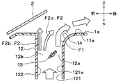
図1に示すように、空気吹出装置10は、吹出口11と、ダクト12と、気流偏向ドア13とを備える。吹出口11は、対象空間としての車室内空間に空気を吹き出す。吹出口11は、インストルメントパネル1の上面部1aのうちウインドシールド2側に位置している。換言すると、吹出口11は、上面部1aに対してウインドシールド2を上下方向に平行に投影したときに、上面部1aのうちウインドシールド2と重複する範囲内に位置している。ダクト12は、吹出口11と空調ユニット20とを接続する。気流偏向ドア13は、ダクト12内に位置している。空調ユニット20は、インストルメントパネル1の内部に配置されている。
As shown in FIG. 1, the air blowing device 10 includes an
インストルメントパネル1は、車室内の前方に設けられた計器盤であり、上面部1aと意匠面部(すなわち、正面部)1bとを有している。インストルメントパネル1は、計器類が配置されている部分だけでなく、オーディオやエアコンを収納する部分を含む、車室内の前席の正面に位置するパネル全体をさしている。
The
図2に示すように、吹出口11は、右ハンドル車両の運転席4aの正面と助手席4bの正面の2カ所に配置されている。以下では、運転席4aの正面の吹出口11について説明するが、助手席4bの正面に配置された吹出口11も運転席4aの正面の吹出口11と同様である。
As shown in FIG. 2, the
吹出口11は、左右方向に細長く延伸している。すなわち、吹出口11の開口形状の長手方向が左右方向に沿っている。吹出口11の左右方向の長さは、座席4の左右方向の長さよりも長い。なお、吹出口11の左右方向の長さは、座席4の左右方向の長さと同等またはそれよりも短くてもよい。
The
図3に示すように、吹出口11は、2辺の長辺11a、11bを有して一方向(すなわち、左右方向)に延びた扁平形状である。
As shown in FIG. 3, the
具体的には、吹出口11の開口縁部11a、11b、11c、11dは、上面部1aの表面において、一対の長辺11a、11bおよび一対の短辺11c、11dを有する。一対の長辺11a、11bは、それぞれ、後方側と前方側に位置するとともに、左右方向に延伸している。一対の短辺11c、11dは、一対の長辺11a、11bの端部同士をつないでいる。本実施形態では、一対の長辺11a、11bが、後方から前方に向かって凸となるように湾曲している。
Specifically, the opening
吹出口11は、図1に示す気流偏向ドア13により、デフロスタモード、アッパーベントモードおよびフェイスモードの3つの吹出モードを切り替えて、温度調整された空気を対象空間としての車室内空間に吹き出す。ここで、デフロスタモードは、ウインドシールド2に向けて空気を吹き出し、窓の曇りを晴らす。フェイスモードは、前席乗員5の上半身に向けて空気を吹き出す。アッパーベントモードは、フェイスモード時よりも上方に向けて空気を吹き出し、後席乗員に送風する。
The
図1に示すように、吹出口11は、ダクト12の末端に形成された開口部によって構成されている。換言すれば、ダクト12は吹出口11に連なっている。ダクト12は、吹出口11の空気流れ上流側に連なる空気流路を内部に形成する流路形成部である。ダクト12は、空調ユニット20と別体として構成された樹脂製のものであり、空調ユニット20と接続されている。ダクト12の空気流れ上流側の端部が空調ユニット20のデフロスタ/フェイス開口部30に連なっている。したがって、ダクト12は、空調ユニット20から送風される空気が流れる空気流路を内部に形成している。なお、ダクト12は、空調ユニット20と一体に形成されていても良い。
As shown in FIG. 1, the
図4に示すように、ダクト12は、後方側に位置する第1の壁(すなわち、後方壁)121と、前方側に位置する第2の壁(すなわち、前方壁)122とを有する。第1の壁121と第2の壁122は、前後方向で対向している。したがって、本実施形態では、前後方向が「第1の壁121と第2の壁122が対向する方向」に対応している。また、左右方向が「第1の壁121と第2の壁122が対向する方向に対して交差する方向」に対応している。また、前方から後方に向かう方向が「第2の壁122から第1の壁121に向かう方向」に対応している。また、後方から前方に向かう方向が「第1の壁121から第2の壁122に向かう方向」に対応している。
As shown in FIG. 4, the
第1の壁121の空気流れ下流側端部が、図3に示す吹出口11の開口縁部のうち後方側の長辺11aを構成している。より詳細には、後述するガイド壁14の端部が、吹出口11の長辺11aを構成している。
The air flow downstream end of the
また、第2の壁122の空気流れ下流側端部が、図3に示す吹出口11の開口縁部のうち前方側の長辺11bを構成している。より詳細には、後述する突出部15の先端が、吹出口11の長辺11bを構成している。
Further, the downstream end of the
気流偏向ドア13は、ダクト12内に流速が異なる2つの気流を発生させる気流偏向部材である。気流偏向ドア13は、ダクト12の内部の第1流路12aと第2流路12bのそれぞれの気流の速度を変更する。第1流路12aは、気流偏向ドア13とダクト12の第1の壁121との間に形成されている。第2流路12bは、気流偏向ドア13とダクト12の第2の壁122との間に形成されている。
The air
本実施形態では、気流偏向ドア13として、バタフライドアを採用している。バタフライドアは、板状のドア本体部と、ドア本体部の中心部に設けられた回転軸とを備える。回転軸は、吹出口11の長手方向(すなわち、車両左右方向)に平行に配置されている。このため、気流偏向ドア13は、吹出口11の長手方向を軸心として回転する。ドア本体部の車両前後方向長さは、車両前後方向におけるダクト12の幅よりも小さい。このため、気流偏向ドア13を水平にしてもダクト12は閉じられない。回転軸は、ダクト12の車両前後方向での中心よりも車両後方側に位置する。これは、第1流路12aの流路断面積を小さくして、第1流路12aに高速の気流を形成するためである。
In the present embodiment, a butterfly door is employed as the air
また、ダクト12の第1の壁121は、吹出口11側の部分にガイド壁14を有する。ガイド壁14は、インストルメントパネル1の上面部1aに連なっている。ガイド壁14は、後述する高速の気流をコアンダ効果によって壁面に沿わせて曲げることで、高速の気流の向きを吹出口11から後方に向かう向きとするように、高速の気流をガイドする。換言すれば、ガイド壁14は、空気流路を流れる空気を第2の壁122から第1の壁121に向かう方向に吹出口から吹き出るようにガイドする。ガイド壁14によって、ダクト12の吹出口11側部分における流路幅、すなわち、第1の壁121と第2の壁122との間隔が、空気流れ下流側に向かって広がっている。本実施形態では、ガイド壁14は、壁面がダクト12の内部に向けて凸となるように湾曲している。換言すれば、ガイド壁14は、第1の壁121のうち吹出口11側の部分よりも空気流れ上流側の部分121aから、第2の壁122に対して離れるように湾曲している。
In addition, the
また、ダクト12は、第2の壁122から第1の壁121に向かって突出した突出部15を有している。この突出部15は、後述する第2の壁122に沿って流れる低速の気流を第2の壁122から第1の壁121に向かう方向に向かわせるためのものである。
Also, the
突出部15は、第2の壁122のうち空気流れ最下流部に位置する。突出部15は、平板形状であり、突出部15の上面とインストルメントパネル1の上面部1aの表面とが面一で連なっている。突出部15の先端は、前後方向において、第1の状態のときの気流偏向ドア13よりも前方側(すなわち、第2の壁122側)に位置する。突出部15は、第2の壁122と一体に形成されている。なお、突出部15は、第2の壁122と別体として形成されていてもよい。
The
また、図3に示すように、突出部15は、第2の壁122において、吹出口11の左右方向の全域に形成されている。本実施形態では、突出部15の突出量L1は、吹出口11の左右方向の全域で均一である。なお、図3では、第2の壁122のうち突出部15よりも空気流れ上流側の部分の壁面の位置を破線で示している。このことは、後述する図11においても同様である。
Further, as shown in FIG. 3, the protruding
図5に示すように、空調ユニット20は、外殻を構成する空調ケーシング21を有する。この空調ケーシング21は、空調対象空間である車室内へ空気を導く空気通路を構成している。空調ケーシング21の空気流れ最上流部には、車室内の空気(すなわち、内気)を吸入する内気吸入口22と車室外の空気(すなわち、外気)を吸入する外気吸入口23とが形成される。さらに、空調ケーシング21の空気流れ最上流部には、内気吸入口22および外気吸入口23を選択的に開閉する吸入口開閉ドア24が設けられている。これら内気吸入口22、外気吸入口23、および吸入口開閉ドア24は、空調ケーシング21内への吸入空気を内気および外気に切り替える内外気切替部を構成している。なお、吸入口開閉ドア24は、図示しない制御装置から出力される制御信号により、その作動が制御される。
As shown in FIG. 5, the
吸入口開閉ドア24の空気流れ下流側には、車室内へ空気を送風する送風装置としての送風機25が配置されている。本実施形態の送風機25は、遠心多翼ファン25aを駆動源である電動モータ25bにより駆動する電動送風機であって、図示しない制御装置から出力される制御信号により回転数(すなわち、送風量)が制御される。
On the downstream side of the air flow of the suction port opening / closing
送風機25の空気流れ下流側には、送風機25により送風された空気を冷却する冷却器として機能する蒸発器26が配置されている。蒸発器26は、その内部を流通する冷媒と空気とを熱交換させる熱交換器であり、図示しない圧縮機、凝縮器、膨張弁等と共に蒸気圧縮式の冷凍サイクルを構成する。
An
蒸発器26の空気流れ下流側には、蒸発器26にて冷却された空気を加熱する加熱器として機能するヒータコア27が配置されている。本実施形態のヒータコア27は、車両エンジンの冷却水を熱源として空気を加熱する熱交換器である。なお、蒸発器26およびヒータコア27は、車室内へ送風する空気の温度を調整する温度調整部を構成している。
A
また、蒸発器26の空気流れ下流側には、蒸発器26通過後の空気を、ヒータコア27を迂回して流す冷風バイパス通路28が形成されている。ここで、ヒータコア27および冷風バイパス通路28の空気流れ下流側にて混合される空気の温度は、ヒータコア27を通過する空気および冷風バイパス通路28を通過する空気の風量割合によって変化する。このため、蒸発器26の空気流れ下流側であって、ヒータコア27および冷風バイパス通路28の入口側には、エアミックスドア29が配置されている。このエアミックスドア29は、ヒータコア27および冷風バイパス通路28へ流入する冷風の風量割合を連続的に変化させるもので、蒸発器26およびヒータコア27と共に温度調整部として機能する。エアミックスドア29は、制御装置から出力される制御信号によってその作動が制御される。
Further, on the downstream side of the air flow of the
空調ケーシング21の空気流れ最下流部には、デフロスタ/フェイス開口部30やフット開口部31が設けられている。デフロスタ/フェイス開口部30は、ダクト12を介して、インストルメントパネル1の上面部1aに設けられた吹出口11に連なっている。フット開口部31は、フットダクト32を介して、フット吹出口33に連なっている。
A defroster /
そして、デフロスタ/フェイス開口部30の空気流れ上流側には、デフロスタ/フェイス開口部30を開閉するデフロスタ/フェイスドア34が配置されている。また、フット開口部31の空気流れ上流側には、フット開口部31を開閉するフットドア35が配置されている。デフロスタ/フェイスドア34およびフットドア35は、車室内へ送風される空気の吹出状態を切り替える吹出モードドアである。
A defroster /
気流偏向ドア13は、所望の吹出モードとなるように、これらの吹出モードドア34、35と連動して作動する。気流偏向ドア13および吹出モードドア34、35は、制御装置から出力される制御信号によってその作動が制御される。なお、気流偏向ドア13および吹出モードドア34、35は、乗員のマニュアル操作によってもドア位置が変更可能となっている。
The air
例えば、吹出モードとして、フット吹出口33から乗員の足元に吹き出すフットモードが実行される場合、デフロスタ/フェイスドア34がデフロスタ/フェイス開口部30を閉じるとともに、フットドア35がフット開口部31を開く。一方、吹出モードとして、デフロスタモード、アッパーベントモード、フェイスモードのいずれか1つが実行される場合、デフロスタ/フェイスドア34がデフロスタ/フェイス開口部30を開くとともに、フットドア35がフット開口部31を閉じる。さらに、この場合、気流偏向ドア13の位置が所望の吹出モードに応じた位置となる。
For example, when the foot mode in which the
本実施形態では、気流偏向ドア13が回転することにより、第1流路12aを通過する気流と、第2流路12bを通過する気流のそれぞれの速度を変更する。これにより、吹出角度θ1を変更する。なお、ここでいう吹出角度θ1とは、図4に示すように、鉛直方向に対して吹出方向がなす角度である。ちなみに、鉛直方向を基準としているのは、第1の壁121のうちガイド壁14よりも空気流れ上流側の部分121aと第2の壁122との間を通過する気流の向きが下から上に向かう方向だからである。
In the present embodiment, the rotation of the air
具体的には、吹出モードがフェイスモードの場合、気流偏向ドア13のドア角度φを図6に示す角度とする。すなわち、気流偏向ドア13のドア本体部を、ドア本体部と第1の壁121との距離が空気の流れ方向に進むにつれて小さくなるように傾ける。これにより、第1流路12aの断面積が第2流路12bの断面積よりも小さくなる。相対的に、第1流路12aに高速の気流F1が発生するとともに、第2流路12bに低速の気流F2が発生する第1状態となる。すなわち、第2流路12bの気流よりも高速の気流F1が第1流路12aに発生するとともに、第1流路11aの気流よりも低速の気流F2が第2流路12bに発生する第1状態となる。上記の第1流路12aの断面積とは、第1流路12aの空気流れを横切る横断面の面積を意味する。上記の第2流路12bの断面積とは、第1流路12aの空気流れを横切る横断面の面積を意味する。
Specifically, when the blowout mode is the face mode, the door angle φ of the
第1状態のときでは、高速の気流F1が、コアンダ効果によってガイド壁14に沿って流れることで、後方側に曲げられる。このとき、高速の気流F1が流れることによって、気流偏向ドア13の下流側に負圧が生じる。このため、低速の気流F2が気流偏向ドア13の下流側に引き込まれ、高速の気流F1側に曲げられながら高速の気流F1に合流する。これにより、ダクト12の内部を流れる空気が車両後方側に曲げられて吹出口11から吹き出される際の最大の曲げ角度θを大きくできる。この結果、空調ユニット20で温度調整された空気、例えば冷風が、吹出口11から前席乗員の上半身に向かって吹き出される。
In the first state, the high-speed air flow F1 is bent backward by flowing along the
このとき、気流偏向ドア13の位置(すなわち、ドア角度)を乗員が手動で調節したり、制御装置が自動調節したりすることにより、高速の気流F1と低速の気流F2の速度差を調整することができる。高速の気流F1と低速の気流F2の速度差が大きいほど、吹出口11から吹き出される空気の曲がり角度が大きくなる。これにより、フェイスモード時の吹出角度θを任意の角度にすることが可能である。
At this time, the passenger manually adjusts the position of the air flow deflection door 13 (that is, the door angle) or the control device automatically adjusts the speed difference between the high speed air flow F1 and the low speed air flow F2. be able to. As the speed difference between the high speed air flow F1 and the low speed air flow F2 increases, the bending angle of the air blown out from the
また、このフェイスモード時では、図3中の矢印のように、吹出口11から乗員5に向かって空気が吹き出される。
Further, in the face mode, air is blown out from the
ここで、ガイド壁14に沿って曲げられた空気の吹出口11からの吹出方向は、ガイド壁14に沿って空気が流れることから、吹出口11を構成する開口縁部11a、11b、11c、11dのうちガイド壁14に連なる長辺11aの形状によって決まる。すなわち、開口縁部のうちガイド壁14に連なる長辺11aの垂線方向が空気の吹出方向となる。なお、長辺11aの垂線方向とは、長辺11aが直線状の場合は、長辺11aの垂線方向のことであり、長辺11aが曲線状の場合は、長辺11aの接線の垂線方向のことである。
Here, since the air flows from the
本実施形態では、図3に示すように、吹出口11を構成する開口縁部のうちガイド壁14に連なる長辺11aが、後方から前方に向かって凸形状であるので、吹出口11からの吹出空気を収束させることができ、吹出空気を乗員5に集中させることができる。
In the present embodiment, as shown in FIG. 3, since the
吹出モードがデフロスタモードの場合、気流偏向ドア13のドア角度を図7に示す角度とする。すなわち、気流偏向ドア13のドア本体部を、ドア本体部と第2の壁122との距離が空気の流れ方向に進むにつれて小さくなるように傾ける。これにより、第1流路12aと第2流路12bのそれぞれに速度が同じもしくは同じに近い気流F3、F4が発生する第2状態となる。第2状態では、気流F3、F4は、それぞれ、上向きに流れる。このため、空調ユニット20で温度調整された空気、例えば温風が、吹出口11からウインドシールド2に向かって吹き出される。
When the blowout mode is the defroster mode, the door angle of the
なお、吹出モードがデフロスタモードの場合、気流偏向ドア13の向きをドア本体部が上下方向に平行となる向きとしてもよい。このとき、第1流路12aの気流と第2流路12bの気流は、同じ速度となる。
When the blowout mode is the defroster mode, the direction of the air
また、図示しないが、吹出モードがアッパーベントモードの場合、気流偏向ドア13の向きを、フェイスモード時とデフロスタモード時の間の向きとする。この場合も第1状態となるが、フェイスモードの場合よりも高速の気流F1が遅いので、フェイスモードの場合よりも吹出角度θ1が小さくなる。この結果、空調ユニット20で温度調整された空気、例えば冷風が、吹出口11から後席乗員に向かって吹き出される。
Further, although not shown, when the blowout mode is the upper vent mode, the direction of the air
次に、本実施形態の主な特徴について説明する。 Next, main features of the present embodiment will be described.
(1)本実施形態の空気吹出装置10では、ダクト12の第2の壁122に突出部15が設けられている。
(1) In the air blowing device 10 of the present embodiment, the projecting
ここで、図8に比較例1の空気吹出装置を示す。比較例1の空気吹出装置は、上記した従来の空気吹出装置に対応し、本実施形態の空気吹出装置10に対して、突出部15を有していない点のみが異なる。
Here, the air blowing apparatus of the comparative example 1 is shown in FIG. The air blowing device of Comparative Example 1 corresponds to the above-described conventional air blowing device, and differs from the air blowing device 10 of the present embodiment only in that the projecting
図8に示すように、比較例1の空気吹出装置では、気流偏向ドア13が第1状態のとき、第2流路12bからの低速の気流F2のうち第2の壁122から離れた側の気流F2aは、高速の気流F1に引き込まれる。しかし、低速の気流F2のうち第2の壁122に近い側の気流F2bは、第2の壁122に沿って流れるため、高速の気流F1に引き込まれない。このため、低速の気流F2bが吹出口11から拡散してしまう。
As shown in FIG. 8, in the air blowing device of Comparative Example 1, when the air
これに対して、本実施形態の空気吹出装置10では、図6に示すように、気流偏向ドア13が第1状態のとき、突出部15によって、第2の壁122に沿って流れる低速の気流F2を第2の壁122から第1の壁121に向かう方向に導くことができる。このため、低速の気流F2の全体を高速の気流F1に引き込ませることができる。よって、本実施形態の空気吹出装置10によれば、比較例1の空気吹出装置と比較して、高速の気流F1に引きこまれる低速の気流F1を増大でき、車両後方に向かって吹出口11から吹き出される吹出風の風量を増大させることができる。
On the other hand, in the air blowing device 10 of the present embodiment, as shown in FIG. 6, when the air
この突出部15の突出量については、図9、10に示すように、次のように設定することが好ましい。
The amount of protrusion of the
図10は、図9に示す突出部15の突出量L1と、突出部15と気流偏向ドア13の距離L2との比(すなわち、L1/L2)に対する低速の気流F2の曲がり角度θ2および吹出圧損の関係を示す図である。これは、本発明者が、突出部15の突出量L1が種々の大きさの本実施形態の空気吹出装置10を用いて、曲がり角度θ2および吹出圧損を測定した実験結果である。なお、吹出圧損とは、吹出口11からの吹出風の圧力損失である。
FIG. 10 shows the bending angle .theta.2 of the air flow F2 at a low speed with respect to the ratio of the projection amount L1 of the
突出部15の突出量L1は、前後方向での第2の壁122の表面から突出部15の先端までの距離である。より詳細には、次の通りである。気流偏向ドア13が第1状態のときに、第2の壁122のうち気流偏向ドア13との距離が最も短い位置を基準位置Psとする。このときの前後方向での第2の壁122の基準位置Psから突出部15の先端までの距離が突出量L1である。
The protrusion amount L1 of the
また、突出部15と気流偏向ドア13の距離L2は、突出部15の先端と気流偏向ドア13との前後方向での距離である。より詳細には、気流偏向ドア13が第1状態のときに、気流偏向ドア13のうち最も第2の壁122に近い端部と、突出部15の先端との前後方向での距離である。
The distance L2 between the
突出量L1が0のとき、L2に対するL1の比(すなわち、L1/L2)は0であり、突出量L1が0から増加するにつれて、L2に対するL1の比(すなわち、L1/L2)も増大する。 When the projection amount L1 is 0, the ratio of L1 to L2 (that is, L1 / L2) is 0, and as the projection amount L1 increases from 0, the ratio of L1 to L2 (that is, L1 / L2) also increases .
図10に示すように、L2に対するL1の比(すなわち、L1/L2)が増大するほど、低速気流F2の曲がり角度θ2が大きくなるが、吹出圧損が増大してしまう。ここで、本発明者の実験において、低速の気流F2を高速の気流F1に合流させるためには、低速の気流F2の曲がり角度θ2は、70度以上にすればよいことが確認されている。また、吹出圧損が20Pa以下であれば、吹出風の風量低下の影響が小さいことが確認されている。 As shown in FIG. 10, as the ratio of L1 to L2 (that is, L1 / L2) increases, the bending angle θ2 of the low speed air flow F2 increases, but the blowout pressure loss increases. Here, in the experiment of the inventor of the present invention, it has been confirmed that the bending angle θ2 of the low speed air flow F2 should be 70 degrees or more in order to merge the low speed air flow F2 with the high speed air flow F1. In addition, it has been confirmed that if the blowing pressure loss is 20 Pa or less, the influence of the reduction of the blowing volume is small.
そこで、突出部15の突出量L1を、下記の数式(1)を満たすように設定する。
Therefore, the protrusion amount L1 of the
1.5≦L1/L2≦1.7・・・(1)
これにより、比較例1の空気吹出装置と比較して、車両後方に向かって吹出口11から吹き出す吹出風の風量を増大させることができる。1.5 ≦ L1 / L2 ≦ 1.7 (1)
As a result, compared to the air blowing device of Comparative Example 1, it is possible to increase the volume of the blowing air blown out from the
(2)本実施形態の空気吹出装置10では、突出部15は、第2の壁122のうち空気流れ最下流部に位置している。そして、突出部15の上面とインストルメントパネル1の上面部1aの表面とが面一で連なっている。この場合、突出部15が上面部1aの一部を構成するとともに、突出部15の先端が吹出口11の開口縁部11bを構成することになる。
(2) In the air blowing device 10 of the present embodiment, the
このため、本実施形態の空気吹出装置10によれば、比較例1の空気吹出装置と比較して、吹出口11の前後方向での開口幅を小さくでき、インストルメントパネル1の意匠性を向上できる。
For this reason, according to the air blowing device 10 of the present embodiment, compared with the air blowing device of Comparative Example 1, the opening width in the front and back direction of the
(第2実施形態)
本実施形態の空気吹出装置10は、第1実施形態の空気吹出装置10において、吹出口11の左右方向の両端部における突出部15の突出量L1を大きくしたものであり、その他の構成は、第1実施形態の空気吹出装置10と同じである。なお、吹出口11の前後方向が吹出口11の縦方向であり、吹出口11の左右方向が吹出口11の横方向である。Second Embodiment
In the air blowing device 10 of the first embodiment, the air blowing device 10 of the present embodiment is obtained by increasing the protrusion amount L1 of the protruding
図11に示すように、本実施形態においても、突出部15は、第2の壁122において、吹出口11の左右方向の全域に形成されている。図12、13と図14とを比較してわかるように、本実施形態では、吹出口11の左右方向における第2の壁122の両端部の突出部15a、15bの突出量L1a、L1bが、吹出口11の左右方向における第2の壁122の両端部よりも中央側の突出部15cの突出量L1cよりも大きくなっている。
As shown in FIG. 11, also in the present embodiment, the
さらに、図11に示すように、吹出口11の左右方向における第2の壁122の両端部よりも中央側における突出部15cの突出量L1cは、吹出口11の左右方向の両端部よりも中央側の範囲内全域で均一である。一方、吹出口11の左右方向における第2の壁の122の両端部の突出部15a、15bの突出量L1a、L1bは、吹出口11の左右方向における中央側から端に向かうにつれて徐々に大きくなっている。
Furthermore, as shown in FIG. 11, the protrusion amount L1 c of the
このため、突出部15a、15bの先端が構成する辺11b1、11b2と吹出口11の開口縁部の後方側の長辺11aとの間隔が、突出部15cの先端が構成する辺11b3と吹出口11の開口縁部の後方側の長辺11aとの間隔と比較して、吹出口11の左右方向における中央側から端に向かうにつれて徐々に狭くなっている。すなわち、吹出口11の左右方向の両端部では、吹出口11の前後方向における開口幅が、吹出口11の左右方向における中央側から端に向かうにつれて徐々に狭くなっている。
Therefore, the distance between the sides 11b1 and 11b2 formed by the tips of the projecting
また、突出部15cの先端が構成する辺11b3は、吹出口11の長辺11aに沿って湾曲している。
Further, the
一方、突出部15aの先端が構成する辺11b1は、直線状となっている。そして、図15に示すように、辺11b1に垂直な仮想直線VL1を吹出口11からの吹出方向側に延長させたとき、この仮想直線Vl1が狙いの点P1を通過するように、辺11b1の向きが設定されている。なお、図15では、仮想直線VL1を、辺11b1の中心点から延ばしているが、辺11b1のいずれの点から延ばしてもよい。
On the other hand, the
突出部15bの先端が構成する辺11b2も、辺11b1と同様の直線状である。ただし、左右方向に対する角度は、辺11b1と辺11b2では異なっている。したがって、本実施形態では、突出部15aと突出部15bの先端形状は非対称である。
The
なお、本実施形態では、突出部15cの突出量L1cのみを、第1実施形態で説明した数式(1)を満たすように、設定すればよい。
In the present embodiment, only the protrusion amount L1c of the
次に、本実施形態の主な特徴について説明する。 Next, main features of the present embodiment will be described.
(1)本実施形態では、第2の壁122の左右方向の両端部における突出部15a、15bの突出量L1a、L1bが、第2の壁122の左右方向の両端部よりも内側の部位における突出部15cの突出量L1cよりも大きくなっている。
(1) In the present embodiment, the projecting amounts L1a and L1b of the
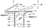
ここで、第1実施形態のように、第2の壁122の左右方向全域で、突出部15の突出量L1が均一の場合について説明する。この場合、吹出口11の左右方向の両端部では、図16に示すように、気流偏向ドア13が第1状態とされるフェイスモード時に、低速気流F2が、吹出口11の短辺11c、11dに連なるダクト12の側壁123、124に沿って流れる。側壁123、124に沿って流れる低速気流F2が、吹出口11から上に向かって吹き出される。このため、吹出口11の左右後方の両端部では、吹出口11の左右後方の両端部よりも内側の部位と比較して、高速の気流F1に合流する低速の気流F2が少なくなってしまう。
Here, as in the first embodiment, the case where the protrusion amount L1 of the
これに対して、図12、13に示すように、本実施形態では、吹出口11の左右方向の両端部において、突出部15a、15bの突出量L1a、L1bを大きくしている。このため、ダクト12の側壁123、124の近くを流れる低速の気流F2を第1の壁121に向けることができる。これにより、吹出口11の左右方向の両端部において、高速の気流F1に合流する低速の気流F2を増大でき、前方から後方に向かう方向に吹出口11から吹き出す吹出風の風量をより増大させることができる。
On the other hand, as shown to FIG. 12, 13, in this embodiment, protrusion amount L1a, L1b of
(2)本実施形態では、第2の壁122の左右方向の両端部における突出部15a、15bの突出量L1a、L1bが、左右方向の中央側から端に向かうにつれて、徐々に大きくなっている。そして、突出部15a、15bの先端が構成する辺11b1、11b2が、直線状となっている。この辺11b1、11b2の垂線方向は、狙いの点P1である乗員5の顔を向いている。
(2) In the present embodiment, the protrusion amounts L1a and L1b of the
ここで、気流偏向ドア13が第1状態とされるフェイスモード時において、辺11b1、11b2の垂線方向が、低速の気流F2の流れ方向となる。このため、本実施形態では、低速の気流F2が狙いの点P1に向かうように、辺11b、11cの向きが設定されている。
Here, in the face mode in which the air
これにより、図11に示すように、フェイスモード時において、吹出口11の左右方向の両端部を流れる低速の気流F2を、乗員5の顔に向けることができる。この結果、低速の気流F2が合流する高速の気流F1も、乗員5の顔に導くことができる。なお、このことは、本発明者が行った実験で確認されている。
As a result, as shown in FIG. 11, in the face mode, the low speed air flow F2 flowing through both end portions of the
したがって、本実施形態によれば、第1実施形態と比較して、乗員5の顔の位置での風速を上げることができる。本発明者が行った実験では、吹出口11の中央から後方へ1m離れた地点P1での風速が、0.5m/s上がることが確認されている。
Therefore, according to the present embodiment, it is possible to increase the wind speed at the position of the face of the
(第3実施形態)
本実施形態の空気吹出装置10は、第1実施形態の空気吹出装置10に対して、突出部の形状が異なるものであり、その他の構成は、第1実施形態の空気吹出装置10と同じである。Third Embodiment
The air blowing device 10 of the present embodiment is different from the air blowing device 10 of the first embodiment in the shape of the projecting portion, and the other configuration is the same as the air blowing device 10 of the first embodiment. is there.
図17に示すように、本実施形態の空気吹出装置10においても、ダクト12の第2の壁122に突出部16が設けられている。この突出部16は、第1実施形態の突出部15に対応するものである。
As shown in FIG. 17, also in the air blowing device 10 of the present embodiment, the projecting
突出部16は、突出部16の先端よりも空気流れ上流側に、前方側に向かって凸状に湾曲する湾曲面16aを有する。この湾曲面16aは、第2の壁122のうち突出部16の空気流れ上流側の位置から突出部16の先端の位置まで延びている。
The
ここで、第1実施形態のように、突出部15が、板状であって、第2の壁122の表面から直交する方向に延びている場合、フェイスモード時に、突出部15の空気流れ上流側に淀みが発生する。
Here, as in the first embodiment, when the
これに対して、本実施形態によれば、フェイスモード時に、湾曲面16aに沿って低速の気流F2を流すことができ、ダクト12の内部において、突出部16の空気流れ上流側に淀みが発生することを回避できる。
On the other hand, according to the present embodiment, in the face mode, the low speed air flow F2 can flow along the
(他の実施形態)
本開示は上記した実施形態に限定されるものではなく、下記のように、請求の範囲に記載した範囲内において適宜変更が可能である。また、本開示は、上記各実施形態に対する以下のような変形例および均等範囲の変形例も許容される。(Other embodiments)
The present disclosure is not limited to the above-described embodiment, and may be appropriately modified within the scope of the claims as described below. Furthermore, the present disclosure allows for the following modifications and equivalent scope modifications to the above-described embodiments.
(1)上記各実施形態では、突出部15、16は、第2の壁122の空気流れ最下流部に位置していたが、この位置よりも空気流れ上流側に位置していてもよい。突出部15、16は、第2の壁122のうち気流偏向ドア13よりも空気流れ下流側の部位に位置していればよい。
(1) In the above embodiments, the
(2)突出部15、16の形状は、上記各実施形態で説明した形状に限られない。突出部15、16は、第2の壁122から第1の壁121に向かって突出し、第2の壁122に沿って流れる低速の気流F2を第2の壁122から第1の壁121に向かう方向に向かわせることができる形状であればよい。
(2) The shapes of the
(3)第2実施形態では、第2の壁122の左右方向の両端部における突出部15a、15bの突出量L1a、L1bが、左右方向の中央側から端に向かうにつれて、徐々に大きくなっていたが、これに限られない。第2の壁122の左右方向の両端部において、突出部15a、15bの突出量L1a、L1bが一定であってもよい。第2の壁122の左右方向の両端部における突出部15a、15bの突出量L1a、L1bが、第2の壁122の左右方向の両端部よりも内側の部位における突出部15cの突出量L1cよりも大きくなっていれば、第2実施形態で説明した(1)の効果が得られる。
(3) In the second embodiment, the protrusion amounts L1a and L1b of the
また、突出部15a、15bの突出量L1a、L1bの両方に限らず、これらの一方が、第2の壁122の左右方向の両端部よりも内側の部位における突出部15cの突出量L1cよりも大きくなっていればよい。これにより、第2実施形態で説明した(1)の効果が得られる。
Further, not limited to both of the projecting amounts L1a and L1b of the projecting
また、第2実施形態では、突出部15が、第2の壁122において、吹出口11の左右方向の全域に形成されていたが、これに限られない。吹出口11の左右方向における第2の壁122の両端部よりも中央側の範囲内において、突出部15cが形成されている部分と、突出部15cが形成されていない部分とがあってもよい。吹出口11の左右方向における第2の壁122の両端部の突出部15a、15bのうちどちらか一方のみが形成されていてもよい。すなわち、突出部15は、少なくとも、第2の壁122のうち吹出口11の左右方向での端部と、第2の壁122のうち吹出口11の左右方向での端部よりも中央側の部分とに形成されていればよい。このとき、第2実施形態と同様に、端部での突出部15の突出量は、中央側の部分での突出部15の突出量よりも大きくされる。これにより、第2実施形態で説明した(1)の効果が得られる。さらに、第2実施形態と同様に、端部での突出部15の突出量は、吹出口11の左右方向における中央側から端側に向かうにつれて徐々に大きくされる。これにより、第2実施形態で説明した(2)の効果が得られる。
Moreover, in 2nd Embodiment, although the
(4)第2実施形態では、突出部15a、15bの先端が構成する辺11b1、11b2が直線状であって、この辺11b1、11b2の垂線方向が、狙いの点P1である乗員5の顔を向いていた。しかし、突出部15a、15bの先端が構成する辺11b1、11b2の形状は直線状に限らす、曲線であってもよい。例えば、第1の壁121から第2の壁122に向かう方向に凸の円弧形状としてもよい。この場合、辺11b1、11b2の接線の垂線方向が、狙いの点P1を向くようにする。これにより、第2実施形態で説明した(2)の効果が得られる。
(4) In the second embodiment, the sides 11b1 and 11b2 formed by the tips of the projecting
(5)上記各実施形態では、吹出口11の平面形状が湾曲した形状であったが、直線状に延びた形状であってもよい。すなわち、ガイド壁14の先端によって構成される吹出口11の長辺11aが曲線でなく、直線であってもよい。
(5) In each said embodiment, although the planar shape of the
(6)上記各実施形態では、吹出口11が一方向に延びた扁平形状であったが、扁平形状でなくてもよい。すなわち、吹出口11の開口縁部における一対の辺11a、11bと一対の辺11c、11dが同じ長さであってもよい。
(6) In each said embodiment, although the
(7)上記各実施形態では、気流偏向ドア13として、バタフライドアを採用したが、スライドドア等の他のドアを採用してもよい。スライドドアを採用する場合、気流偏向ドア13の位置を、第1流路12aの断面積が第2流路12bの断面積よりも小さくなる位置とする。これにより、第1流路12aに高速の気流が発生するとともに、第2流路12bに低速の気流が発生する第1状態となる。
(7) In each of the above embodiments, a butterfly door is employed as the air
(8)上記各実施形態では、本開示の空気吹出装置をインストルメントパネル1の上面部1aの吹出口11に適用したが、本開示の空気吹出装置をインストルメントパネル1の下面の吹出口(すなわち、フット吹出口)に適用しても良い。この場合、フット吹出口から吹き出される空気の吹出角度を任意に変更することができる。また、上記各実施形態では、本開示の空気吹出装置を車両用空調装置に適用したが、本開示の空気吹出装置を車両以外の空調装置に適用しても良い。
(8) In the above embodiments, the air blowing device of the present disclosure is applied to the
(9)上記各実施形態は、互いに無関係なものではなく、組み合わせが明らかに不可な場合を除き、適宜組み合わせが可能である。また、上記各実施形態において、実施形態を構成する要素は、特に必須であると明示した場合および原理的に明らかに必須であると考えられる場合等を除き、必ずしも必須のものではないことは言うまでもない。 (9) The above embodiments are not mutually unrelated, and combinations can be appropriately made unless combinations are obviously not possible. Further, in each of the above-described embodiments, it is needless to say that the elements constituting the embodiment are not necessarily essential except when clearly indicated as being essential and when it is considered to be obviously essential in principle. Yes.
Claims (10)
対象空間に空気を吹き出す吹出口(11)と、
第1の壁(121)および前記第1の壁に対向する第2の壁(122)を有し、前記吹出口の空気流れ上流側に連なる空気流路を内部に形成する流路形成部(12)と、
前記空気流路に設けられ、前記空気流路に流速が異なる2つの気流を発生させる気流偏向部材(13)とを備え、
前記空気流路において、前記気流偏向部材と前記第1の壁との間を第1流路(12a)とし、前記気流偏向部材と前記第2の壁との間を第2流路(12b)としたとき、
前記気流偏向部材は、相対的に、前記第1流路に高速の気流(F1)が発生するとともに、前記第2流路に低速の気流(F2)が発生するように構成されており、
前記第1の壁のうち前記吹出口側の一部は、前記気流偏向部材が発生させた前記第1流路からの高速の気流を壁面に沿わせて曲げて、前記高速の気流の向きを前記第2の壁から前記第1の壁に向かう方向とするように、前記高速の気流をガイドするガイド壁(14)を構成し、
前記流路形成部は、前記第2の壁のうち前記気流偏向部材よりも空気流れ下流側の部位において、前記第2の壁から前記第1の壁に向かって突出し、前記第2の壁に沿って流れる低速の気流を前記第2の壁から前記第1の壁に向かう方向に向かわせる突出部(15、16)を有し、
前記吹出口は、前記第1の壁と前記第2の壁とが対向する方向を縦方向とし、前記第1の壁と前記第2の壁とが対向する方向に対して交差する方向を横方向とし、
前記突出部は、前記吹出口の横方向における前記第2の壁の全域に形成されており、
前記吹出口の横方向における前記第2の壁の両端部の少なくとも一方での前記突出部の突出量が、前記吹出口の横方向における前記第2の壁の両端部よりも内側の部位での前記突出部の突出量よりも大きくなっている空気吹出装置。 An air blowing device for blowing out air;
An outlet (11) for blowing air into the target space,
A flow passage forming portion (having a first wall (121) and a second wall (122) opposite to the first wall, the air flow passage being continuous with the air flow upstream side of the blowout port 12) and
And an air flow deflection member (13) provided in the air flow path and generating two air flows having different flow rates in the air flow path,
In the air flow path, the space between the air flow deflection member and the first wall is a first flow path (12a), and the space between the air flow deflection member and the second wall is a second flow path (12b) And when
The air flow deflection member is configured to relatively generate a high speed air flow (F1) in the first flow path, and generate a low speed air flow (F2) in the second flow path,
A part of the first wall on the air outlet side of the first wall bends the high-speed air flow from the first flow path generated by the air flow deflection member along the wall surface to direct the high-speed air flow A guide wall (14) for guiding the high-speed air flow so as to be directed from the second wall to the first wall;
The flow passage forming portion protrudes from the second wall toward the first wall at a portion of the second wall on the downstream side of the air flow deflection member with respect to the air flow deflection member, and the flow passage forming portion is formed on the second wall protrusion for directing the low speed airflow flowing along the direction toward the first wall from the second wall have a (15, 16),
The blowout port has a longitudinal direction in which the first wall and the second wall face each other, and a transverse direction in which the first wall and the second wall intersect each other. Direction
The protrusion is formed on the entire area of the second wall in the lateral direction of the outlet,
The amount of protrusion of the protrusion at at least one of the ends of the second wall in the lateral direction of the outlet is at a location inside the ends of the second wall in the lateral direction of the outlet. air blowing device that is larger than the projection amount of the projecting portion.
対象空間に空気を吹き出す吹出口(11)と、
第1の壁(121)および前記第1の壁に対向する第2の壁(122)を有し、前記吹出口の空気流れ上流側に連なる空気流路を内部に形成する流路形成部(12)と、
前記空気流路に設けられ、前記空気流路に流速が異なる2つの気流を発生させる気流偏向部材(13)とを備え、
前記空気流路において、前記気流偏向部材と前記第1の壁との間を第1流路(12a)とし、前記気流偏向部材と前記第2の壁との間を第2流路(12b)としたとき、
前記気流偏向部材は、前記第1流路の断面積が前記第2流路の断面積よりも小さくなることにより、前記第2流路の気流よりも高速の気流(F1)が前記第1流路に発生するとともに、前記第1流路の気流よりも低速の気流(F2)が前記第2流路に発生するように構成されており、
前記第1の壁のうち前記吹出口側の一部は、前記気流偏向部材が発生させた前記第1流路からの高速の気流を壁面に沿わせて曲げて、前記高速の気流の向きを前記第2の壁から前記第1の壁に向かう方向とするように、前記高速の気流をガイドするガイド壁(14)を構成し、
前記流路形成部は、前記第2の壁のうち前記気流偏向部材よりも空気流れ下流側の部位において、前記第2の壁から前記第1の壁に向かって突出し、前記第2の壁に沿って流れる低速の気流を前記第2の壁から前記第1の壁に向かう方向に向かわせる突出部(15、16)を有し、
前記吹出口は、前記第1の壁と前記第2の壁とが対向する方向を縦方向とし、前記第1の壁と前記第2の壁とが対向する方向に対して交差する方向を横方向とし、
前記突出部は、前記吹出口の横方向における前記第2の壁の全域に形成されており、
前記吹出口の横方向における前記第2の壁の両端部の少なくとも一方での前記突出部の突出量が、前記吹出口の横方向における前記第2の壁の両端部よりも内側の部位での前記突出部の突出量よりも大きくなっている空気吹出装置。 An air blowing device for blowing out air;
An outlet (11) for blowing air into the target space,
A flow passage forming portion (having a first wall (121) and a second wall (122) opposite to the first wall, the air flow passage being continuous with the air flow upstream side of the blowout port 12) and
And an air flow deflection member (13) provided in the air flow path and generating two air flows having different flow rates in the air flow path,
In the air flow path, the space between the air flow deflection member and the first wall is a first flow path (12a), and the space between the air flow deflection member and the second wall is a second flow path (12b) And when
In the air flow deflection member, when the cross sectional area of the first flow path is smaller than the cross sectional area of the second flow path, the air flow (F1) having a higher speed than the air flow of the second flow path is the first flow An air flow (F2) that is generated in the passage and is slower than the air flow in the first flow passage is generated in the second flow passage, and
A part of the first wall on the air outlet side of the first wall bends the high-speed air flow from the first flow path generated by the air flow deflection member along the wall surface to direct the high-speed air flow A guide wall (14) for guiding the high-speed air flow so as to be directed from the second wall to the first wall;
The flow passage forming portion protrudes from the second wall toward the first wall at a portion of the second wall on the downstream side of the air flow deflection member with respect to the air flow deflection member, and the flow passage forming portion is formed on the second wall protrusion for directing the low speed airflow flowing along the direction toward the first wall from the second wall have a (15, 16),
The blowout port has a longitudinal direction in which the first wall and the second wall face each other, and a transverse direction in which the first wall and the second wall intersect each other. Direction
The protrusion is formed on the entire area of the second wall in the lateral direction of the outlet,
The amount of protrusion of the protrusion at at least one of the ends of the second wall in the lateral direction of the outlet is at a location inside the ends of the second wall in the lateral direction of the outlet. air blowing device that is larger than the projection amount of the projecting portion.
対象空間に空気を吹き出す吹出口(11)と、
第1の壁(121)および前記第1の壁に対向する第2の壁(122)を有し、前記吹出口の空気流れ上流側に連なる空気流路を内部に形成する流路形成部(12)と、
前記空気流路に設けられ、前記空気流路に流速が異なる2つの気流を発生させる気流偏向部材(13)とを備え、
前記空気流路において、前記気流偏向部材と前記第1の壁との間を第1流路(12a)とし、前記気流偏向部材と前記第2の壁との間を第2流路(12b)としたとき、
前記気流偏向部材は、相対的に、前記第1流路に高速の気流(F1)が発生するとともに、前記第2流路に低速の気流(F2)が発生するように構成されており、
前記第1の壁のうち前記吹出口側の一部は、前記気流偏向部材が発生させた前記第1流路からの高速の気流を壁面に沿わせて曲げて、前記高速の気流の向きを前記第2の壁から前記第1の壁に向かう方向とするように、前記高速の気流をガイドするガイド壁(14)を構成し、
前記流路形成部は、前記第2の壁のうち前記気流偏向部材よりも空気流れ下流側の部位において、前記第2の壁から前記第1の壁に向かって突出し、前記第2の壁に沿って流れる低速の気流を前記第2の壁から前記第1の壁に向かう方向に向かわせる突出部(15、16)を有し、
前記吹出口は、前記第1の壁と前記第2の壁とが対向する方向を縦方向とし、前記第1の壁と前記第2の壁とが対向する方向に対して交差する方向を横方向とし、
前記突出部は、少なくとも、前記第2の壁のうち前記横方向での端部と、前記第2の壁のうち前記横方向での前記端部よりも中央側の部分とに形成されており、
前記端部での前記突出部の突出量が、前記中央側の部分での前記突出部の突出量よりも大きくなっている空気吹出装置。 An air blowing device for blowing out air;
An outlet (11) for blowing air into the target space,
A flow passage forming portion (having a first wall (121) and a second wall (122) opposite to the first wall, the air flow passage being continuous with the air flow upstream side of the blowout port 12) and
And an air flow deflection member (13) provided in the air flow path and generating two air flows having different flow rates in the air flow path,
In the air flow path, the space between the air flow deflection member and the first wall is a first flow path (12a), and the space between the air flow deflection member and the second wall is a second flow path (12b) And when
The air flow deflection member is configured to relatively generate a high speed air flow (F1) in the first flow path, and generate a low speed air flow (F2) in the second flow path,
A part of the first wall on the air outlet side of the first wall bends the high-speed air flow from the first flow path generated by the air flow deflection member along the wall surface to direct the high-speed air flow A guide wall (14) for guiding the high-speed air flow so as to be directed from the second wall to the first wall;
The flow passage forming portion protrudes from the second wall toward the first wall at a portion of the second wall on the downstream side of the air flow deflection member with respect to the air flow deflection member, and the flow passage forming portion is formed on the second wall protrusion for directing the low speed airflow flowing along the direction toward the first wall from the second wall have a (15, 16),
The blowout port has a longitudinal direction in which the first wall and the second wall face each other, and a transverse direction in which the first wall and the second wall intersect each other. Direction
The projecting portion is formed at least at an end portion in the lateral direction of the second wall and a portion on the central side of the end portion in the lateral direction of the second wall. ,
The projecting amount of the projecting portion, the air blowing device that is larger than the projection amount of the projecting portion at a portion of said central side in the end.
対象空間に空気を吹き出す吹出口(11)と、
第1の壁(121)および前記第1の壁に対向する第2の壁(122)を有し、前記吹出口の空気流れ上流側に連なる空気流路を内部に形成する流路形成部(12)と、
前記空気流路に設けられ、前記空気流路に流速が異なる2つの気流を発生させる気流偏向部材(13)とを備え、
前記空気流路において、前記気流偏向部材と前記第1の壁との間を第1流路(12a)とし、前記気流偏向部材と前記第2の壁との間を第2流路(12b)としたとき、
前記気流偏向部材は、前記第1流路の断面積が前記第2流路の断面積よりも小さくなることにより、前記第2流路の気流よりも高速の気流(F1)が前記第1流路に発生するとともに、前記第1流路の気流よりも低速の気流(F2)が前記第2流路に発生するように構成されており、
前記第1の壁のうち前記吹出口側の一部は、前記気流偏向部材が発生させた前記第1流路からの高速の気流を壁面に沿わせて曲げて、前記高速の気流の向きを前記第2の壁から前記第1の壁に向かう方向とするように、前記高速の気流をガイドするガイド壁(14)を構成し、
前記流路形成部は、前記第2の壁のうち前記気流偏向部材よりも空気流れ下流側の部位において、前記第2の壁から前記第1の壁に向かって突出し、前記第2の壁に沿って流れる低速の気流を前記第2の壁から前記第1の壁に向かう方向に向かわせる突出部(15、16)を有し、
前記吹出口は、前記第1の壁と前記第2の壁とが対向する方向を縦方向とし、前記第1の壁と前記第2の壁とが対向する方向に対して交差する方向を横方向とし、
前記突出部は、少なくとも、前記第2の壁のうち前記横方向での端部と、前記第2の壁のうち前記横方向での前記端部よりも中央側の部分とに形成されており、
前記端部での前記突出部の突出量が、前記中央側の部分での前記突出部の突出量よりも大きくなっている空気吹出装置。 An air blowing device for blowing out air;
An outlet (11) for blowing air into the target space,
A flow passage forming portion (having a first wall (121) and a second wall (122) opposite to the first wall, the air flow passage being continuous with the air flow upstream side of the blowout port 12) and
And an air flow deflection member (13) provided in the air flow path and generating two air flows having different flow rates in the air flow path,
In the air flow path, the space between the air flow deflection member and the first wall is a first flow path (12a), and the space between the air flow deflection member and the second wall is a second flow path (12b) And when
In the air flow deflection member, when the cross sectional area of the first flow path is smaller than the cross sectional area of the second flow path, the air flow (F1) having a higher speed than the air flow of the second flow path An air flow (F2) that is generated in the passage and is slower than the air flow in the first flow passage is generated in the second flow passage, and
A part of the first wall on the air outlet side of the first wall bends the high-speed air flow from the first flow path generated by the air flow deflection member along the wall surface to direct the high-speed air flow A guide wall (14) for guiding the high-speed air flow so as to be directed from the second wall to the first wall;
The flow passage forming portion protrudes from the second wall toward the first wall at a portion of the second wall on the downstream side of the air flow deflection member with respect to the air flow deflection member, and the flow passage forming portion protrusion for directing the low speed airflow flowing along the direction toward the first wall from the second wall have a (15, 16),
The blowout port has a longitudinal direction in which the first wall and the second wall face each other, and a transverse direction in which the first wall and the second wall intersect each other. Direction
The projecting portion is formed at least at an end portion in the lateral direction of the second wall and a portion on the central side of the end portion in the lateral direction of the second wall. ,
The projecting amount of the projecting portion, the air blowing device that is larger than the projection amount of the projecting portion at a portion of said central side in the end.
1.5≦L1/L2≦1.7・・・(1)
を満たす請求項1ないし6のいずれか1つに記載の空気吹出装置。 Assuming that the amount of protrusion of the protrusion is L1, and the distance between the tip of the protrusion and the airflow deflection member in the direction in which the first wall and the second wall face is L2, the following formula ( 1)
1.5 ≦ L1 / L2 ≦ 1.7 (1)
The air blowing apparatus according to any one of claims 1 to 6, wherein
対象空間に空気を吹き出す吹出口(11)と、
第1の壁(121)および前記第1の壁に対向する第2の壁(122)を有し、前記吹出口の空気流れ上流側に連なる空気流路を内部に形成する流路形成部(12)と、
前記空気流路に設けられ、前記空気流路に流速が異なる2つの気流を発生させる気流偏向部材(13)とを備え、
前記空気流路において、前記気流偏向部材と前記第1の壁との間を第1流路(12a)とし、前記気流偏向部材と前記第2の壁との間を第2流路(12b)としたとき、
前記気流偏向部材は、相対的に、前記第1流路に高速の気流(F1)が発生するとともに、前記第2流路に低速の気流(F2)が発生するように構成されており、
前記第1の壁のうち前記吹出口側の一部は、前記気流偏向部材が発生させた前記第1流路からの高速の気流を壁面に沿わせて曲げて、前記高速の気流の向きを前記第2の壁から前記第1の壁に向かう方向とするように、前記高速の気流をガイドするガイド壁(14)を構成し、
前記流路形成部は、前記第2の壁のうち前記気流偏向部材よりも空気流れ下流側の部位において、前記第2の壁から前記第1の壁に向かって突出し、前記第2の壁に沿って流れる低速の気流を前記第2の壁から前記第1の壁に向かう方向に向かわせる突出部(15、16)を有し、
前記突出部の突出量をL1とし、前記第1の壁と前記第2の壁とが対向する方向での前記突出部の先端と前記気流偏向部材との距離をL2としたとき、下記数式(1)
1.5≦L1/L2≦1.7・・・(1)
を満たす空気吹出装置。 An air blowing device for blowing out air;
An outlet (11) for blowing air into the target space,
A flow passage forming portion (having a first wall (121) and a second wall (122) opposite to the first wall, the air flow passage being continuous with the air flow upstream side of the blowout port 12) and
And an air flow deflection member (13) provided in the air flow path and generating two air flows having different flow rates in the air flow path,
In the air flow path, the space between the air flow deflection member and the first wall is a first flow path (12a), and the space between the air flow deflection member and the second wall is a second flow path (12b) And when
The air flow deflection member is configured to relatively generate a high speed air flow (F1) in the first flow path, and generate a low speed air flow (F2) in the second flow path,
A part of the first wall on the air outlet side of the first wall bends the high-speed air flow from the first flow path generated by the air flow deflection member along the wall surface to direct the high-speed air flow A guide wall (14) for guiding the high-speed air flow so as to be directed from the second wall to the first wall;
The flow passage forming portion protrudes from the second wall toward the first wall at a portion of the second wall on the downstream side of the air flow deflection member with respect to the air flow deflection member, and the flow passage forming portion is formed on the second wall protrusion for directing the low speed airflow flowing along the direction toward the first wall from the second wall have a (15, 16),
Assuming that the amount of protrusion of the protrusion is L1, and the distance between the tip of the protrusion and the airflow deflection member in the direction in which the first wall and the second wall face is L2, the following formula ( 1)
1.5 ≦ L1 / L2 ≦ 1.7 (1)
An air blowing device that meets
対象空間に空気を吹き出す吹出口(11)と、
第1の壁(121)および前記第1の壁に対向する第2の壁(122)を有し、前記吹出口の空気流れ上流側に連なる空気流路を内部に形成する流路形成部(12)と、
前記空気流路に設けられ、前記空気流路に流速が異なる2つの気流を発生させる気流偏向部材(13)とを備え、
前記空気流路において、前記気流偏向部材と前記第1の壁との間を第1流路(12a)とし、前記気流偏向部材と前記第2の壁との間を第2流路(12b)としたとき、
前記気流偏向部材は、前記第1流路の断面積が前記第2流路の断面積よりも小さくなることにより、前記第2流路の気流よりも高速の気流(F1)が前記第1流路に発生するとともに、前記第1流路の気流よりも低速の気流(F2)が前記第2流路に発生するように構成されており、
前記第1の壁のうち前記吹出口側の一部は、前記気流偏向部材が発生させた前記第1流路からの高速の気流を壁面に沿わせて曲げて、前記高速の気流の向きを前記第2の壁から前記第1の壁に向かう方向とするように、前記高速の気流をガイドするガイド壁(14)を構成し、
前記流路形成部は、前記第2の壁のうち前記気流偏向部材よりも空気流れ下流側の部位において、前記第2の壁から前記第1の壁に向かって突出し、前記第2の壁に沿って流れる低速の気流を前記第2の壁から前記第1の壁に向かう方向に向かわせる突出部(15、16)を有し、
前記突出部の突出量をL1とし、前記第1の壁と前記第2の壁とが対向する方向での前記突出部の先端と前記気流偏向部材との距離をL2としたとき、下記数式(1)
1.5≦L1/L2≦1.7・・・(1)
を満たす空気吹出装置。 An air blowing device for blowing out air;
An outlet (11) for blowing air into the target space,
A flow passage forming portion (having a first wall (121) and a second wall (122) opposite to the first wall, the air flow passage being continuous with the air flow upstream side of the blowout port 12) and
And an air flow deflection member (13) provided in the air flow path and generating two air flows having different flow rates in the air flow path,
In the air flow path, the space between the air flow deflection member and the first wall is a first flow path (12a), and the space between the air flow deflection member and the second wall is a second flow path (12b) And when
In the air flow deflection member, when the cross sectional area of the first flow path is smaller than the cross sectional area of the second flow path, the air flow (F1) having a higher speed than the air flow of the second flow path is the first flow An air flow (F2) that is generated in the passage and is slower than the air flow in the first flow passage is generated in the second flow passage, and
A part of the first wall on the air outlet side of the first wall bends the high-speed air flow from the first flow path generated by the air flow deflection member along the wall surface to direct the high-speed air flow A guide wall (14) for guiding the high-speed air flow so as to be directed from the second wall to the first wall;
The flow passage forming portion protrudes from the second wall toward the first wall at a portion of the second wall on the downstream side of the air flow deflection member with respect to the air flow deflection member, and the flow passage forming portion is formed on the second wall protrusion for directing the low speed airflow flowing along the direction toward the first wall from the second wall have a (15, 16),
Assuming that the amount of protrusion of the protrusion is L1, and the distance between the tip of the protrusion and the airflow deflection member in the direction in which the first wall and the second wall face is L2, the following formula ( 1)
1.5 ≦ L1 / L2 ≦ 1.7 (1)
An air blowing device that meets
前記突出部は、前記第2の壁のうち空気流れ最下流部に位置し、前記突出部の上面と前記上面部の表面とが面一で連なっている請求項1ないし9のいずれか1つに記載の空気吹出装置。 The air outlet is provided on an upper surface of an instrument panel of a vehicle.
10. The projection according to any one of claims 1 to 9 , wherein the projection is located on the most downstream side of the air flow in the second wall, and the upper surface of the projection and the surface of the upper surface are flush with each other. The air blowing device according to claim 1.
Applications Claiming Priority (3)
| Application Number | Priority Date | Filing Date | Title |
|---|---|---|---|
| JP2015079399 | 2015-04-08 | ||
| JP2015079399 | 2015-04-08 | ||
| PCT/JP2016/057230 WO2016163193A1 (en) | 2015-04-08 | 2016-03-08 | Air discharge device |
Publications (2)
| Publication Number | Publication Date |
|---|---|
| JPWO2016163193A1 JPWO2016163193A1 (en) | 2017-08-31 |
| JP6424953B2 true JP6424953B2 (en) | 2018-11-21 |
Family
ID=57073174
Family Applications (1)
| Application Number | Title | Priority Date | Filing Date |
|---|---|---|---|
| JP2017511506A Expired - Fee Related JP6424953B2 (en) | 2015-04-08 | 2016-03-08 | Air blowing device |
Country Status (2)
| Country | Link |
|---|---|
| JP (1) | JP6424953B2 (en) |
| WO (1) | WO2016163193A1 (en) |
Families Citing this family (1)
| Publication number | Priority date | Publication date | Assignee | Title |
|---|---|---|---|---|
| JP7354559B2 (en) * | 2018-05-11 | 2023-10-03 | 株式会社デンソー | Fluid blowout device |
Family Cites Families (8)
| Publication number | Priority date | Publication date | Assignee | Title |
|---|---|---|---|---|
| JPS5460663A (en) * | 1977-10-24 | 1979-05-16 | Matsushita Electric Ind Co Ltd | Fluid stream direction controller |
| JPS5460662A (en) * | 1977-10-24 | 1979-05-16 | Matsushita Electric Ind Co Ltd | Air blow direction changer |
| JPS5937310A (en) * | 1982-08-24 | 1984-02-29 | Matsushita Electric Ind Co Ltd | Flow direction controller |
| JPS619313U (en) * | 1984-06-25 | 1986-01-20 | 小島プレス工業株式会社 | Automotive indoor air conditioner |
| JPS6335298Y2 (en) * | 1984-12-10 | 1988-09-20 | ||
| JPH01172909U (en) * | 1988-05-25 | 1989-12-07 | ||
| JP2633328B2 (en) * | 1988-10-13 | 1997-07-23 | 松下冷機株式会社 | Wind direction changing device |
| JP2014210564A (en) * | 2013-04-05 | 2014-11-13 | 株式会社デンソー | Air blower |
-
2016
- 2016-03-08 JP JP2017511506A patent/JP6424953B2/en not_active Expired - Fee Related
- 2016-03-08 WO PCT/JP2016/057230 patent/WO2016163193A1/en active Application Filing
Also Published As
| Publication number | Publication date |
|---|---|
| WO2016163193A1 (en) | 2016-10-13 |
| JPWO2016163193A1 (en) | 2017-08-31 |
Similar Documents
| Publication | Publication Date | Title |
|---|---|---|
| WO2015146124A1 (en) | Air-blowing device | |
| WO2014162670A1 (en) | Air blowing device | |
| JP6477970B2 (en) | Air blowing device | |
| WO2016009592A1 (en) | Air blowing device | |
| US20190168566A1 (en) | Air blowout apparatus | |
| WO2016158101A1 (en) | Air blowing device | |
| JP6424953B2 (en) | Air blowing device | |
| JP6547656B2 (en) | Vehicle air blowing device | |
| JP2017149307A (en) | Air blowout device for vehicle | |
| JP5924230B2 (en) | Air conditioner | |
| JP6394796B2 (en) | Air blowing device | |
| JP5092964B2 (en) | Air conditioner for vehicles | |
| JP6399211B2 (en) | Air blowing device | |
| JP5721549B2 (en) | Air conditioner for vehicles | |
| JP6481631B2 (en) | Air blowing device for vehicle | |
| WO2020066524A1 (en) | Blowing device for vehicle | |
| JP2017149305A (en) | Air blowout device for vehicle | |
| JP6565739B2 (en) | Air blowing device for vehicle | |
| JP6658080B2 (en) | Air blowing device for vehicles | |
| JP6634799B2 (en) | Air blowing device for vehicles | |
| JP2017100553A (en) | Air blowout device for vehicle | |
| JP2017149302A (en) | Air blowout device for vehicle | |
| JP6565738B2 (en) | Air blowing device for vehicle | |
| JP2016011009A (en) | Air conditioner for vehicle |
Legal Events
| Date | Code | Title | Description |
|---|---|---|---|
| A621 | Written request for application examination |
Free format text: JAPANESE INTERMEDIATE CODE: A621 Effective date: 20170425 |
|
| A131 | Notification of reasons for refusal |
Free format text: JAPANESE INTERMEDIATE CODE: A131 Effective date: 20180306 |
|
| A521 | Request for written amendment filed |
Free format text: JAPANESE INTERMEDIATE CODE: A523 Effective date: 20180409 |
|
| TRDD | Decision of grant or rejection written | ||
| A01 | Written decision to grant a patent or to grant a registration (utility model) |
Free format text: JAPANESE INTERMEDIATE CODE: A01 Effective date: 20180925 |
|
| A61 | First payment of annual fees (during grant procedure) |
Free format text: JAPANESE INTERMEDIATE CODE: A61 Effective date: 20181008 |
|
| R151 | Written notification of patent or utility model registration |
Ref document number: 6424953 Country of ref document: JP Free format text: JAPANESE INTERMEDIATE CODE: R151 |
|
| LAPS | Cancellation because of no payment of annual fees |