WO2014157706A1 - 医用画像処理装置 - Google Patents
医用画像処理装置 Download PDFInfo
- Publication number
- WO2014157706A1 WO2014157706A1 PCT/JP2014/059359 JP2014059359W WO2014157706A1 WO 2014157706 A1 WO2014157706 A1 WO 2014157706A1 JP 2014059359 W JP2014059359 W JP 2014059359W WO 2014157706 A1 WO2014157706 A1 WO 2014157706A1
- Authority
- WO
- WIPO (PCT)
- Prior art keywords
- blood vessel
- unit
- region
- image processing
- derived
- Prior art date
- Legal status (The legal status is an assumption and is not a legal conclusion. Google has not performed a legal analysis and makes no representation as to the accuracy of the status listed.)
- Ceased
Links
Images







Classifications
-
- A—HUMAN NECESSITIES
- A61—MEDICAL OR VETERINARY SCIENCE; HYGIENE
- A61B—DIAGNOSIS; SURGERY; IDENTIFICATION
- A61B5/00—Measuring for diagnostic purposes; Identification of persons
- A61B5/02—Detecting, measuring or recording for evaluating the cardiovascular system, e.g. pulse, heart rate, blood pressure or blood flow
- A61B5/026—Measuring blood flow
-
- A—HUMAN NECESSITIES
- A61—MEDICAL OR VETERINARY SCIENCE; HYGIENE
- A61B—DIAGNOSIS; SURGERY; IDENTIFICATION
- A61B5/00—Measuring for diagnostic purposes; Identification of persons
- A61B5/72—Signal processing specially adapted for physiological signals or for diagnostic purposes
-
- A—HUMAN NECESSITIES
- A61—MEDICAL OR VETERINARY SCIENCE; HYGIENE
- A61B—DIAGNOSIS; SURGERY; IDENTIFICATION
- A61B5/00—Measuring for diagnostic purposes; Identification of persons
- A61B5/74—Details of notification to user or communication with user or patient; User input means
- A61B5/742—Details of notification to user or communication with user or patient; User input means using visual displays
-
- A—HUMAN NECESSITIES
- A61—MEDICAL OR VETERINARY SCIENCE; HYGIENE
- A61B—DIAGNOSIS; SURGERY; IDENTIFICATION
- A61B5/00—Measuring for diagnostic purposes; Identification of persons
- A61B5/74—Details of notification to user or communication with user or patient; User input means
- A61B5/742—Details of notification to user or communication with user or patient; User input means using visual displays
- A61B5/743—Displaying an image simultaneously with additional graphical information, e.g. symbols, charts, function plots
-
- A—HUMAN NECESSITIES
- A61—MEDICAL OR VETERINARY SCIENCE; HYGIENE
- A61B—DIAGNOSIS; SURGERY; IDENTIFICATION
- A61B6/00—Apparatus or devices for radiation diagnosis; Apparatus or devices for radiation diagnosis combined with radiation therapy equipment
- A61B6/02—Arrangements for diagnosis sequentially in different planes; Stereoscopic radiation diagnosis
- A61B6/03—Computed tomography [CT]
- A61B6/032—Transmission computed tomography [CT]
-
- A—HUMAN NECESSITIES
- A61—MEDICAL OR VETERINARY SCIENCE; HYGIENE
- A61B—DIAGNOSIS; SURGERY; IDENTIFICATION
- A61B6/00—Apparatus or devices for radiation diagnosis; Apparatus or devices for radiation diagnosis combined with radiation therapy equipment
- A61B6/46—Arrangements for interfacing with the operator or the patient
- A61B6/461—Displaying means of special interest
-
- A—HUMAN NECESSITIES
- A61—MEDICAL OR VETERINARY SCIENCE; HYGIENE
- A61B—DIAGNOSIS; SURGERY; IDENTIFICATION
- A61B6/00—Apparatus or devices for radiation diagnosis; Apparatus or devices for radiation diagnosis combined with radiation therapy equipment
- A61B6/50—Apparatus or devices for radiation diagnosis; Apparatus or devices for radiation diagnosis combined with radiation therapy equipment specially adapted for specific body parts; specially adapted for specific clinical applications
- A61B6/504—Apparatus or devices for radiation diagnosis; Apparatus or devices for radiation diagnosis combined with radiation therapy equipment specially adapted for specific body parts; specially adapted for specific clinical applications for diagnosis of blood vessels, e.g. by angiography
-
- A—HUMAN NECESSITIES
- A61—MEDICAL OR VETERINARY SCIENCE; HYGIENE
- A61B—DIAGNOSIS; SURGERY; IDENTIFICATION
- A61B6/00—Apparatus or devices for radiation diagnosis; Apparatus or devices for radiation diagnosis combined with radiation therapy equipment
- A61B6/50—Apparatus or devices for radiation diagnosis; Apparatus or devices for radiation diagnosis combined with radiation therapy equipment specially adapted for specific body parts; specially adapted for specific clinical applications
- A61B6/507—Apparatus or devices for radiation diagnosis; Apparatus or devices for radiation diagnosis combined with radiation therapy equipment specially adapted for specific body parts; specially adapted for specific clinical applications for determination of haemodynamic parameters, e.g. perfusion CT
-
- A—HUMAN NECESSITIES
- A61—MEDICAL OR VETERINARY SCIENCE; HYGIENE
- A61B—DIAGNOSIS; SURGERY; IDENTIFICATION
- A61B6/00—Apparatus or devices for radiation diagnosis; Apparatus or devices for radiation diagnosis combined with radiation therapy equipment
- A61B6/52—Devices using data or image processing specially adapted for radiation diagnosis
- A61B6/5211—Devices using data or image processing specially adapted for radiation diagnosis involving processing of medical diagnostic data
- A61B6/5217—Devices using data or image processing specially adapted for radiation diagnosis involving processing of medical diagnostic data extracting a diagnostic or physiological parameter from medical diagnostic data
-
- A—HUMAN NECESSITIES
- A61—MEDICAL OR VETERINARY SCIENCE; HYGIENE
- A61B—DIAGNOSIS; SURGERY; IDENTIFICATION
- A61B8/00—Diagnosis using ultrasonic, sonic or infrasonic waves
- A61B8/06—Measuring blood flow
-
- A—HUMAN NECESSITIES
- A61—MEDICAL OR VETERINARY SCIENCE; HYGIENE
- A61B—DIAGNOSIS; SURGERY; IDENTIFICATION
- A61B8/00—Diagnosis using ultrasonic, sonic or infrasonic waves
- A61B8/46—Ultrasonic, sonic or infrasonic diagnostic devices with special arrangements for interfacing with the operator or the patient
- A61B8/461—Displaying means of special interest
-
- A—HUMAN NECESSITIES
- A61—MEDICAL OR VETERINARY SCIENCE; HYGIENE
- A61B—DIAGNOSIS; SURGERY; IDENTIFICATION
- A61B8/00—Diagnosis using ultrasonic, sonic or infrasonic waves
- A61B8/52—Devices using data or image processing specially adapted for diagnosis using ultrasonic, sonic or infrasonic waves
- A61B8/5207—Devices using data or image processing specially adapted for diagnosis using ultrasonic, sonic or infrasonic waves involving processing of raw data to produce diagnostic data, e.g. for generating an image
-
- G—PHYSICS
- G06—COMPUTING OR CALCULATING; COUNTING
- G06T—IMAGE DATA PROCESSING OR GENERATION, IN GENERAL
- G06T7/00—Image analysis
- G06T7/0002—Inspection of images, e.g. flaw detection
- G06T7/0012—Biomedical image inspection
-
- G—PHYSICS
- G06—COMPUTING OR CALCULATING; COUNTING
- G06T—IMAGE DATA PROCESSING OR GENERATION, IN GENERAL
- G06T7/00—Image analysis
- G06T7/10—Segmentation; Edge detection
- G06T7/11—Region-based segmentation
-
- G—PHYSICS
- G06—COMPUTING OR CALCULATING; COUNTING
- G06T—IMAGE DATA PROCESSING OR GENERATION, IN GENERAL
- G06T7/00—Image analysis
- G06T7/10—Segmentation; Edge detection
- G06T7/136—Segmentation; Edge detection involving thresholding
-
- G—PHYSICS
- G06—COMPUTING OR CALCULATING; COUNTING
- G06T—IMAGE DATA PROCESSING OR GENERATION, IN GENERAL
- G06T7/00—Image analysis
- G06T7/10—Segmentation; Edge detection
- G06T7/187—Segmentation; Edge detection involving region growing; involving region merging; involving connected component labelling
-
- G—PHYSICS
- G16—INFORMATION AND COMMUNICATION TECHNOLOGY [ICT] SPECIALLY ADAPTED FOR SPECIFIC APPLICATION FIELDS
- G16H—HEALTHCARE INFORMATICS, i.e. INFORMATION AND COMMUNICATION TECHNOLOGY [ICT] SPECIALLY ADAPTED FOR THE HANDLING OR PROCESSING OF MEDICAL OR HEALTHCARE DATA
- G16H50/00—ICT specially adapted for medical diagnosis, medical simulation or medical data mining; ICT specially adapted for detecting, monitoring or modelling epidemics or pandemics
- G16H50/30—ICT specially adapted for medical diagnosis, medical simulation or medical data mining; ICT specially adapted for detecting, monitoring or modelling epidemics or pandemics for calculating health indices; for individual health risk assessment
-
- A—HUMAN NECESSITIES
- A61—MEDICAL OR VETERINARY SCIENCE; HYGIENE
- A61B—DIAGNOSIS; SURGERY; IDENTIFICATION
- A61B8/00—Diagnosis using ultrasonic, sonic or infrasonic waves
- A61B8/08—Clinical applications
- A61B8/0891—Clinical applications for diagnosis of blood vessels
-
- A—HUMAN NECESSITIES
- A61—MEDICAL OR VETERINARY SCIENCE; HYGIENE
- A61B—DIAGNOSIS; SURGERY; IDENTIFICATION
- A61B8/00—Diagnosis using ultrasonic, sonic or infrasonic waves
- A61B8/48—Diagnostic techniques
- A61B8/483—Diagnostic techniques involving the acquisition of a 3D volume of data
-
- A—HUMAN NECESSITIES
- A61—MEDICAL OR VETERINARY SCIENCE; HYGIENE
- A61B—DIAGNOSIS; SURGERY; IDENTIFICATION
- A61B8/00—Diagnosis using ultrasonic, sonic or infrasonic waves
- A61B8/52—Devices using data or image processing specially adapted for diagnosis using ultrasonic, sonic or infrasonic waves
- A61B8/5215—Devices using data or image processing specially adapted for diagnosis using ultrasonic, sonic or infrasonic waves involving processing of medical diagnostic data
- A61B8/5223—Devices using data or image processing specially adapted for diagnosis using ultrasonic, sonic or infrasonic waves involving processing of medical diagnostic data for extracting a diagnostic or physiological parameter from medical diagnostic data
-
- G—PHYSICS
- G06—COMPUTING OR CALCULATING; COUNTING
- G06T—IMAGE DATA PROCESSING OR GENERATION, IN GENERAL
- G06T2207/00—Indexing scheme for image analysis or image enhancement
- G06T2207/10—Image acquisition modality
- G06T2207/10072—Tomographic images
-
- G—PHYSICS
- G06—COMPUTING OR CALCULATING; COUNTING
- G06T—IMAGE DATA PROCESSING OR GENERATION, IN GENERAL
- G06T2207/00—Indexing scheme for image analysis or image enhancement
- G06T2207/20—Special algorithmic details
- G06T2207/20092—Interactive image processing based on input by user
- G06T2207/20104—Interactive definition of region of interest [ROI]
-
- G—PHYSICS
- G06—COMPUTING OR CALCULATING; COUNTING
- G06T—IMAGE DATA PROCESSING OR GENERATION, IN GENERAL
- G06T2207/00—Indexing scheme for image analysis or image enhancement
- G06T2207/30—Subject of image; Context of image processing
- G06T2207/30004—Biomedical image processing
- G06T2207/30096—Tumor; Lesion
-
- G—PHYSICS
- G06—COMPUTING OR CALCULATING; COUNTING
- G06T—IMAGE DATA PROCESSING OR GENERATION, IN GENERAL
- G06T2207/00—Indexing scheme for image analysis or image enhancement
- G06T2207/30—Subject of image; Context of image processing
- G06T2207/30004—Biomedical image processing
- G06T2207/30101—Blood vessel; Artery; Vein; Vascular
-
- G—PHYSICS
- G06—COMPUTING OR CALCULATING; COUNTING
- G06T—IMAGE DATA PROCESSING OR GENERATION, IN GENERAL
- G06T2207/00—Indexing scheme for image analysis or image enhancement
- G06T2207/30—Subject of image; Context of image processing
- G06T2207/30172—Centreline of tubular or elongated structure
-
- G—PHYSICS
- G06—COMPUTING OR CALCULATING; COUNTING
- G06T—IMAGE DATA PROCESSING OR GENERATION, IN GENERAL
- G06T5/00—Image enhancement or restoration
- G06T5/20—Image enhancement or restoration using local operators
- G06T5/30—Erosion or dilatation, e.g. thinning
-
- G—PHYSICS
- G06—COMPUTING OR CALCULATING; COUNTING
- G06T—IMAGE DATA PROCESSING OR GENERATION, IN GENERAL
- G06T7/00—Image analysis
- G06T7/60—Analysis of geometric attributes
- G06T7/66—Analysis of geometric attributes of image moments or centre of gravity
Definitions
- Embodiments described herein relate generally to a medical image processing apparatus.
- Interventional treatment is performed by medical imaging technology using an X-ray diagnostic apparatus.
- an interventional treatment is performed by a doctor or the like while generating and displaying an in-vivo image of a subject with an X-ray diagnostic apparatus.
- the doctor or the like guides the catheter inserted into the subject to a predetermined site in the subject while referring to the blood vessel in the displayed image.
- a doctor inserts a guide wire from the base of a foot or the like.
- the doctor also guides the affected area using a catheter along the guide wire.
- a doctor or the like performs embolization of a predetermined part while referring to the image.
- the embolization is performed, for example, by placing an occlusive substance such as a coil from a distal end of the catheter at a predetermined site.
- the site to be embolized is an aneurysm, an inflow blood vessel to AVM (Arteriovenous malformation), an inflow blood vessel to a tumor, or the like.
- This embolization prevents blood flow to the inflowing blood vessels.
- the blood flow to Nidus is blocked by occluding the blood vessels that flow into Nidus.
- Aneurysms are treated by coagulating blood within the aneurysm by placing a coil.
- it is possible to block the blood flow to the tumor by closing the blood vessel that flows into the nutrient blood vessels that flow to the tumor.
- a doctor performs an embolization operation to block an inflow blood vessel to a predetermined site while referring to a medical image. Therefore, it is desirable for a doctor to be able to smoothly grasp the inflow blood vessel and its surrounding area.
- a technique for facilitating the grasp of the inflow blood vessel portion in the medical image has been proposed.
- This embodiment is intended to provide a medical image processing apparatus capable of improving the visibility of blood vessels flowing into or out of an affected area in a medical image.
- the medical image processing apparatus includes an acquisition unit, an identification unit, an identification unit, and a display control unit.
- the acquisition unit acquires volume data indicating a state of a three-dimensional region including a lump and a plurality of blood vessels derived from the lump in the subject.
- the identification unit specifies a region corresponding to a plurality of blood vessels derived from the lump portion and the lump portion in the volume data.
- the identifying unit identifies the identified region as a region of interest.
- the identification unit identifies each of the mass and the plurality of blood vessels in the identified region of interest.
- the display control unit changes at least one of the display modes of the identified mass and each of the plurality of blood vessels.
- FIG. 1 is a schematic block diagram showing an overview of an image processing apparatus according to a first embodiment.
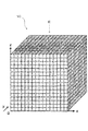
- Schematic which shows volume data notionally.
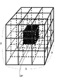
- Schematic which shows notion of the center point based on the designated point by an identification part notionally.
- Schematic which shows the area
- Schematic which shows the area
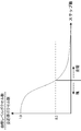
- the graph which shows the outline of the correspondence of the number of region growing steps and the ratio of the object part voxel to the number of all neighboring voxels.
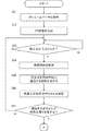
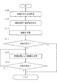
- 3 is a schematic flowchart showing an outline of the operation of the image processing apparatus according to the first embodiment.
- 3 is a schematic flowchart showing an outline of the operation of the image processing apparatus according to the first embodiment.
- 10 is a schematic flowchart showing an outline of an operation of an image processing apparatus according to Modification 4 of the first embodiment.
- 10 is a schematic flowchart showing an outline of an operation of an image processing apparatus according to Modification 4 of the first embodiment.
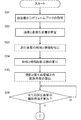
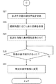
- 9 is a schematic flowchart showing an outline of the operation of the medical image processing apparatus according to the second embodiment.
- 9 is a schematic flowchart showing an outline of the operation of the medical image processing apparatus according to the second embodiment.
- the schematic block diagram which shows the outline
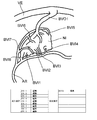
- summary of the list screen concerning 4th Embodiment Schematic which shows notionally the identification process of the derived blood vessel concerning 4th Embodiment.
- FIGS. 1 to 5 A medical image processing apparatus or an image acquisition apparatus according to the first to fifth embodiments will be described with reference to FIGS.
- FIG. 1 is a block diagram illustrating a schematic configuration of a medical image processing system according to the first embodiment.
- the medical image processing system includes an image processing device 10, an image acquisition device 20A to an image acquisition device 20C,... An image acquisition device 20n, and an image storage device 30. These devices are connected to each other via a network N so that data communication is possible.
- the image acquisition device 20A, the image acquisition device 20B, the image acquisition device 20C, and the image storage device 30 are connected to the network as an example, but the number of each device can be arbitrarily set. .
- the image processing apparatus 10 and the plurality of image acquisition apparatuses 20A, 20B, 20C,..., The image acquisition apparatus 20n can transmit and receive a plurality of tomographic images or volume data via a network.
- the image storage device 30 stores tomographic images or volume data generated in the image acquisition device 20A, the image acquisition device 20B, the image acquisition device 20C,. Further, the image storage device 30 sends the stored volume data and the like to the image processing device 10 in response to a request from the image processing device 10.
- the image acquisition device 20A and the like are described as an image acquisition device for medical images that collects information on the body tissue of a subject.
- an X-ray image acquisition apparatus X-ray Angio apparatus
- an X-ray CT image acquisition apparatus X-ray CT image acquisition apparatus
- an MRI image acquisition apparatus MRI image acquisition apparatus
- an ultrasonic image acquisition apparatus or the like.
- the image storage device 30 is based on, for example, PACS (Pictures Archiving and Communication System).
- the image storage device 30 is an image management device having an image database.
- the image management apparatus manages medical image data in the image database by a program.
- the image storage device 30 may be a file server that stores medical image data such as a network attached storage (NAS).
- NAS network attached storage
- the image processing apparatus 10 (Outline of image processing device)
- the image processing apparatus 10 acquires volume data relating to a medical image.
- the image processing apparatus 10 identifies a lump portion and a blood vessel derived from the lump portion in the volume data, and identifies the identified region as a region of interest.
- the image processing apparatus 10 according to the first embodiment is configured to acquire volume data acquired in advance by the image acquisition apparatuses 20A to 20C and stored in the image storage apparatus 30.
- information on a body tissue of a subject, reconstruction processing, and generation of volume data may be performed. .
- the image processing apparatus 10 includes a display unit D, an operation unit C, an acquisition unit 1, an image processing unit 2, a display control unit 3, a designation unit 4, an identification unit 5, and an extraction unit 6.
- a display unit D As shown in FIG. 1, the image processing apparatus 10 includes a display unit D, an operation unit C, an acquisition unit 1, an image processing unit 2, a display control unit 3, a designation unit 4, an identification unit 5, and an extraction unit 6.
- the configuration of each unit in the image processing apparatus 10 will be described.
- the display unit D is a CRT (Cathode Ray Tube) display, an LCD (Liquid Crystal Display), an organic EL (OELD; Organic Electro-Luminescence Display), or an FED (Field Emission Display) display device. Is done.
- the display unit D displays various operation screens, setting screens, and medical images under the control of the display control unit 3.
- the operation unit C includes an arbitrary form of operation device and input device such as a keyboard, a mouse, a trackball, a joystick, and a control panel.
- input device such as a keyboard, a mouse, a trackball, a joystick, and a control panel.
- a part of the operation unit C and the display unit D such as a touch panel can be configured by the same device.
- a main control unit (not shown) receives the operation signal output from the operation unit C based on the performed operation, and executes the above-described control of each unit corresponding to the operation content.
- the acquisition unit 1 receives an operation signal from the operation unit C and executes a volume data acquisition request to the image storage device 30. For example, in the image processing apparatus 10, a user inputs a patient ID or an examination ID via the operation unit C and an operation related to a volume data acquisition request is performed. When the operation is performed, the acquisition unit 1 requests the image storage device 30 to acquire volume data based on the ID input according to the operation.
- the image storage device 30 searches for volume data in accordance with the acquisition request. Further, the image storage device 30 reads the volume data corresponding to the ID or the like and sends it to the image processing device 10.
- the acquisition unit 1 stores at least temporarily the volume data received from the image storage device 30.
- the acquisition unit 1 includes an arbitrary storage medium such as a RAM (Random Access Memory), a HDD (Hard Disk Drive), or an SSD (Solid State Drive).
- the volume data may be stored in another storage device.
- the acquisition unit 1 may store the volume data.
- the acquisition unit 1 may store a volume rendering image in the two-dimensional image processing.
- the acquisition unit 1 stores image processing conditions for two-dimensional image processing (volume rendering processing, surface rendering processing, etc.) for volume data.
- the image processing unit 2 performs image processing related to generation of a two-dimensional image on the volume data by an image processing operation via the operation unit C. For example, when the user performs an operation of generating a volume rendering (VR) image based on the volume data, the image processing unit 2 receives an instruction related to the operation. In response to the instruction, the image processing unit 2 causes the display unit D to display a setting screen for setting various parameters related to the volume rendering process via the display control unit 3.
- the various parameters include, for example, line-of-sight direction setting information for volume rendering processing.
- the various parameters include transparency setting information for each voxel value of each voxel in the volume data.
- the various parameters include setting information of WL (Window Level) and WW (Window Width) in the volume rendering image.
- the image processing unit 2 executes, for example, processing for generating a volume rendering image based on various parameters. For example, the image processing unit 2 determines the position of the light source and the projection direction of the image in the volume rendering process according to the set line-of-sight direction. Further, the image processing unit 2 sets the transparency of each voxel according to the transparency for each set voxel value.
- the image processing unit 2 performs a volume rendering process on the volume data to generate a two-dimensional image.
- the image processing unit 2 is not limited to a configuration that generates a volume rendering image based on various parameters set by the user.
- the image processing unit 2 may generate a volume rendering image using data preset as at least some parameters.
- the two-dimensional image generated by any one of the above processes includes, for example, an aneurysm, an outflow blood vessel from the aneurysm, and AVM (arteriovenous malformation) Niidas And surface shapes such as blood vessels flowing into Nidus or blood vessels flowing into tumors and tumors.
- the image processing unit 2 sends the generated volume rendering image to the display control unit 3. Further, the image processing unit 2 stores parameters such as the line-of-sight direction used for the volume rendering process in association with the target volume data.
- the image processing unit 2 is configured to generate a volume rendering image, but is not limited thereto.
- the image processing unit 2 may generate a surface rendering image, a MIP (Maximum Intensity Projection) image, a MinIP (Minimum Intensity Projection) image, and the like.
- the display control unit 3 performs control to generate a setting screen for various parameters related to the generation of the two-dimensional image generated by the image processing unit 2 as described above and display the screen on the display unit D.
- the display control unit 3 performs control to display the volume rendering image generated by the image processing unit 2 on the display unit D.
- the display control unit 3 performs control for causing the display unit D to display the extracted blood vessel region or the medical image including the mass region and the blood vessel region. The extraction of the blood vessel region and the like will be described later.
- the display control unit 3 performs control for causing the display unit D to display a setting screen related to a display mode such as a blood vessel region. Note that each image described below is described as being displayed on the display unit D as a result of display control by the display control unit 3 unless otherwise specified.
- control for displaying a volume rendering image on the display unit D is performed.
- the image processing apparatus 10 can accept a designation point designation operation described below.
- the following description is given assuming that the volume rendering image shows a block.
- the lump is, for example, Nidus, aneurysm, tumor, etc. in AVM.
- the following description is given on the assumption that the volume rendering image shows a blood vessel connected to the mass portion or a blood vessel derived from the mass portion.
- a lump that indicates Nidus, aneurysm, tumor, or the like may be simply referred to as a “lump”.
- a blood vessel connected to the mass portion or a blood vessel derived from the mass portion may be simply referred to as “derived blood vessel”.
- the display control unit 3 may cause the display unit D to display a message that prompts the user to specify a part of the lump in the volume rendering image, for example, one point in the range indicating the lump in the image. Further, the display control unit 3 may be configured to determine whether or not the volume rendering image includes a region indicating a block.
- the display control unit 3 stores a range of pixel values indicating a blood vessel or a mass. Further, the display control unit 3 stores information on relative sizes with respect to other parts (such as bones) in the lump. The display control unit 3 obtains a range occupied by pixels having pixel values indicating a block portion or the like in the volume rendering image based on the stored information. Also. The display control unit 3 obtains the size of the range based on the number of pixels and the like. The display control unit 3 compares the stored size of the lump with the size of the obtained range. As a result of the comparison, when the size of the lump portion does not reach the stored size, the display control unit 3 displays a warning or the like indicating that the lump portion is not included in the displayed volume rendering image on the display unit D. May be displayed.
- the designating unit 4 accepts an operation of designating a designated point via the operation unit C.
- This designated point is used for the center point identification process by the identification unit 5 described later.
- the designation unit 4 stores the coordinates corresponding to the designated position in the image as the designated point. To do. Further, when the user performs an operation for determining the designated point, the designation unit 4 sends the coordinate information of the designated point to the identification unit 5.
- the designation unit 4 stores the position in the image designated by the user as the designated point.
- the present embodiment is not limited to this.
- the designation unit 4 acquires the coordinates of the region indicating the lump in the image or the coordinates of the outline. .
- the designation unit 4 obtains coordinates corresponding to the center point based on the information on the portion indicating the contour received from the display control unit 3.
- the designating unit 4 may be configured to store the obtained coordinates of the center point as designated points. Further, in this configuration, the designated point may be editable by the user moving with the operation unit C.
- FIG. 2 is a schematic diagram conceptually showing volume data.
- FIG. 3 is a schematic diagram conceptually showing the identification of the center point based on the designated point by the identification unit 5.
- 4A and 4B are schematic diagrams conceptually showing region expansion by the identification unit 5.
- FIG. 5 is a graph showing an outline of a correspondence relationship between the number of region growing steps and the ratio of target part voxels to the total number of neighboring voxels. The following description will be divided into a first identification process that is the identification process of the center point and a second identification process that is the identification process of the mass part and the derived blood vessel.
- center point demonstrated below may be the center of an actual lump part, it does not necessarily show the said center. That is, in this embodiment, the points in the volume data identified in the first identification process are described as “center points” or “designated points” for convenience of explanation.
- the identification unit 5 receives information related to the coordinates of the designated point in the volume rendering image from the designation unit 4. In response to this, the identification unit 5 acquires a volume rendering image related to the designation of the designated point. Further, the identification unit 5 acquires volume data related to the volume rendering image from the acquisition unit 1. Further, the identification unit 5 acquires image processing conditions for two-dimensional image processing (volume rendering processing, surface rendering processing, etc.) for the volume data stored in the acquisition unit 1.
- the identification unit 5 obtains the correspondence between the volume rendering image and the volume data based on the acquired image processing conditions and the coordinates of the volume rendering image and the volume data. That is, the identification unit 5 determines which voxel in the volume data each pixel of the volume rendering image corresponds to.
- the identification unit 5 obtains the coordinates of the designated point in the volume data from the correspondence between the coordinates of the designated point in the volume rendering image and the coordinates of the voxel of the volume data. Further, the identification unit 5 extracts the line-of-sight direction (projection direction) of the image with respect to the volume data when the volume rendering process is performed from the image processing condition of the volume rendering image acquired from the acquisition unit 1. Note that if the image processing condition does not include information on the line-of-sight direction of the volume rendering image, the line-of-sight direction is obtained by the identification unit 5 based on the correspondence between the display contents of the volume rendering image and the volume data.
- FIG. 2 shows volume data three-dimensionally.
- FIG. 3 shows an XY cross section orthogonal to the Z-axis direction of FIG. That is, the cross section of FIG. 2 is orthogonal to the volume rendering image orthogonal to the Y-axis direction and along the X-axis and Z-axis directions.
- FIG. 3 shows a concept when the volume data is viewed from the bottom to the top or from the top to the bottom.
- the identification unit 5 obtains a locus RT passing through the specified point DP in the line-of-sight direction (left and right direction in FIG. 2) in the volume data VD. Next, the identification unit 5 extracts the voxel value of the voxel through which the trajectory RT passes, together with the coordinates of the voxel. The identification unit 5 reads setting information of a predetermined voxel value stored in advance. This setting information is a voxel value indicating a lump and a voxel value indicating a blood vessel. Further, the identification unit 5 compares the setting information of the read voxel value with the voxel value of each voxel through which the trajectory RT passes.
- the identification unit 5 discriminates a region corresponding to the lump portion, a region corresponding to the blood vessel, and other regions on the locus RT.
- the voxel value concerning setting information may have a predetermined range.
- the region corresponding to the mass portion and the region corresponding to the blood vessel determined here correspond to an example of “region of interest”, and the other regions correspond to an example of “other portion”.
- the setting information corresponds to an example of “a threshold value for identifying a voxel corresponding to a mass or a blood vessel”. At this time, it has not been determined whether the region corresponding to the blood vessel is a derived blood vessel from the lump.
- the identification unit 5 obtains the coordinates of the voxel having the voxel value corresponding to the setting information among the voxels through which the locus RT passes. Further, the identification unit 5 obtains the widths L1, L2, L3... Ln of the portions where the voxels corresponding to the setting information are continuous on the locus RT. The identifying unit 5 determines the widest width among the obtained widths L1, L2, L3,. In FIG. 2, the width L1 is the widest width. Further, the identification unit 5 obtains the coordinates of the intermediate position of the widest width L1 determined to be a lump based on the coordinates of the start end and the end of L1 (L1 / 2). By such processing, the identification unit 5 identifies the obtained intermediate position as the center point of the lump portion (see FIG. 3; reference symbol CP).
- the identification part 5 calculates
- the second identification process which is the identification process of the clumps and the derived blood vessels by the identification unit 5, will be described with reference to FIG. 3, FIG. 4A, FIG. 4B, and FIG.
- a second identification process an example will be described in which the region of the lump is expanded stepwise by the region growing method and reaches the derived blood vessel.
- an area expanded by one step of region growing an example in which the front and rear two voxels are expanded along the X axis, the Y axis, and the Z axis around the center point CP identified in the first identification process. explain.
- the identification unit 5 subtracts one voxel in the vicinity of 3 ⁇ 3 ⁇ 3 27 voxels, which is 3 voxels on the X axis, 3 voxels on the Y axis, and 3 voxels on the Z axis. Expand the voxel area.
- FIG. 4A conceptually shows a process of expanding voxels near 26 around the center point CP identified in the first identification process in the first step of region growing.
- FIG. 4B conceptually shows an extended range for each of the X axis, the Y axis, and the Z axis including the center point CP in the upper stage. Further, FIG. 4B shows a ratio of a mass portion or a derived blood vessel at a stage where the number of steps of half of the total number n of region growing is reached and other portions in the lower stage.
- the total number n of region growing steps described here indicates the number of steps at the time when identification of the derived blood vessel is completed as a result, and need not be set in advance. However, it includes a configuration in which the total number of region growing steps is set in advance as in a modification example described later.
- the hatched portion in FIGS. 4A and 4B indicates either a lump or a derived blood vessel.
- the identification unit 5 uses the voxel value setting information read out in the first identification process. That is, the setting information is a voxel value indicating a lump and a voxel value indicating a blood vessel. In region growing, the identification unit 5 compares the setting information of the voxel value with the set voxel values of the respective voxels in the vicinity of 26.
- the flow of identification processing of the lump region and the derived blood vessel region by region growing is generally as follows.
- the identification unit 5 performs region expansion while sequentially taking in the connected regions belonging to the lump portion from the center point CP by the above comparison by region growing.
- the identification unit 5 determines the connectivity of the regions based on whether or not the region is within the setting information range with the center point CP as the start point as the center.
- the identification unit 5 is not limited to expanding the region by comparing the setting information with the voxel values of neighboring voxels.
- the identification unit 5 can change the setting information, which is a region expansion condition, according to the change state of the voxel values of surrounding voxels in the process of region expansion processing.
- the identification unit 5 obtains a numerical value indicating a change in voxel values of surrounding voxels in the process of region expansion processing (search processing). Further, the identification unit 5 changes the setting information that is the region expansion condition based on the numerical state indicating the obtained change.
- the identification unit 5 determines that most of the voxels in the range for performing region expansion (such as voxels in the vicinity of 26) correspond to the mass region or the derived blood vessel region, the identification unit 5 searches for the mass range. Judge that you are doing. On the other hand, when it is determined by the second identification process in the identification unit 5 that only a part of the directions has been expanded, the identification unit 5 determines that the search for the derived blood vessel region has started. An example of this determination will be described below.
- the identification unit 5 stores in advance the threshold value of the ratio of the voxel (the number of blood vessel level voxels, etc.) corresponding to the lump region and the derived blood vessel region to the total number of neighboring voxels as a boundary value between the lump portion and the derived blood vessel. As described above, when only a part of the direction is expanded by the second identification process, it can be determined that the derived blood vessel region has been reached. The identification unit 5 determines whether or not only this partial direction is expanded by determining whether the ratio of the voxel corresponding to the lump region or the derived blood vessel region to the total number of neighboring voxels is equal to or less than the threshold value.
- the identification unit 5 determines that the derived blood vessel region has been reached in the region expansion when the value is equal to or less than the threshold value.
- the threshold value of the ratio of voxels corresponding to the lump region or the derived blood vessel region to the total number of neighboring voxels is indicated as “0.23”.
- the identification unit 5 obtains the ratio of the voxel corresponding to the lump region or the derived blood vessel region with respect to the total number of neighboring voxels in each region growing step.
- the identifying unit 5 compares the obtained ratio with a threshold value. As a result of the comparison, the identification unit 5 determines that the region of the derived blood vessel has been reached when the obtained ratio is equal to or less than the threshold value.
- the identification unit 5 After determining that the blood vessel region has been reached, the identification unit 5 performs a thinning process for each region growing step set in advance. As a result, the identification unit 5 identifies the thinned voxel as the center line (axis) of the derived blood vessel in the derived blood vessel. Furthermore, as a result of continuing the region expansion, the identification unit 5 determines whether the center line of the derived blood vessel has a branch. If it is determined that there is a branch, the identification unit 5 ends the expansion process of the derived blood vessel region by region growing. The identification unit 5 sends the coordinate information of the voxel of the mass region identified so far and the coordinate information of the voxel of the derived blood vessel region to the extraction unit 6, and extracts the identified region from the volume data.
- the extraction unit 6 receives the coordinate information of the voxel of the lump identified by the identification unit 5 and the coordinate information of the voxel of the derived blood vessel. Based on the received coordinate information, the extraction unit 6 associates the first region information indicating that it is a block region with the voxel of the block region in the volume data. Similarly, the extraction unit 6 associates the second region information indicating the derived blood vessel region with the voxel of the derived blood vessel region.
- the extraction unit 6 sends volume data associated with various area information to the identification unit 5.
- the identification unit 5 stores the volume data.
- the first area information and the second area information may be identification information such as an ID.
- one or both of the identification unit 5 and the extraction unit 6 corresponds to an example of an “identification unit”.
- Image processing unit display mode changing process
- the image processing unit 2 displays the first area information associated with the volume data. Based on the coordinate information and the coordinate information of the second region information, the mass region and the derived blood vessel region are specified.
- the image processing unit 2 assigns a preset display mode to the specified voxels in each region.
- the image processing unit 2 corresponds to an example of “identification unit” and / or “display control unit”.
- the display mode set in advance is, for example, a display color. That is, the image processing unit 2 displays the extracted mass region and the derived blood vessel region in color display (red or the like), and displays the other portions in gray scale.
- the display mode set in advance is transparency. That is, the image processing unit 2 displays the extracted mass region and the derived blood vessel region with, for example, 0% transparency (opacity 100%), and displays the other portions with transparency 80% (opacity 20%).
- the image processing unit 2 can extract the contours of the lump portion and the derived blood vessel region, and the extracted contours can be made different in color or transparency from other portions. .
- FIGS. 6 and 7 are flowcharts showing an outline of the operation of the image processing apparatus 10 according to the first embodiment.
- the acquisition unit 1 receives an operation signal from the operation unit C and executes a volume data acquisition request to the image storage device 30. As a result, the acquisition unit 1 stores at least temporarily the volume data received from the image storage device 30.
- the image processing unit 2 performs image processing related to generation of a two-dimensional image on the volume data by an image processing operation via the operation unit C. For example, when the user performs an operation for generating a volume rendering (VR) image based on volume data and various parameter settings such as a line-of-sight direction, the image processing unit 2 performs volume rendering according to the set line-of-sight direction according to the operation. The position of the light source and the projection direction of the image are determined. Further, the image processing unit 2 sets the transparency of each voxel according to the transparency for each set voxel value. In this way, the image processing unit 2 performs volume rendering processing on the volume data to generate a pseudo 3D image (2D image).
- VR volume rendering
- the image processing unit 2 sends the generated volume rendering image to the display control unit 3.
- the display control unit 3 performs control to display the volume rendering image generated by the image processing unit 2 on the display unit D. Furthermore, the display control unit 3 may perform display control that prompts the user to specify a part of a lump in the volume rendering image, for example, one point in a range indicating the lump in the image. Further, the display control unit 3 may be configured to determine whether or not the volume rendering image includes a region indicating a block.
- Step 03> When the volume rendering image is displayed on the display unit D, the designating unit 4 determines whether or not a designated point designating operation has been received via the operation unit C. Furthermore, the designation unit 4 determines whether or not a designated point is confirmed. The designation unit 4 repeats this determination until the designation operation and the confirmation operation are performed (S03; No). However, the configuration may be such that the confirmation operation is not performed only by the designation operation. Note that instead of the user's designation, the designation unit 4 may obtain a region indicating the block in the image or its outline, and further obtain a point corresponding to the center thereof. In this configuration, the user may be able to further edit a point corresponding to the center.
- Step 04> As a result of the determination in S03, when the above designation is made by the designation unit 4 and it is further determined that the confirmation operation has been performed (S03; Yes), the designation unit 4 sends the coordinate information of the designated point to the identification unit 5.
- the identification unit 5 acquires a volume rendering image related to the designation of the designated point. Further, the identification unit 5 acquires volume data related to the volume rendering image from the acquisition unit 1. Further, the identification unit 5 acquires the image processing conditions of the two-dimensional image processing for the volume data stored in the acquisition unit 1. Next, the identification unit 5 extracts the line-of-sight direction (projection direction) of the image with respect to the volume data from the acquired image processing conditions.
- the identification unit 5 obtains a locus RT that passes the designated point DP in the line-of-sight direction (left-right direction in FIG. 2) in the volume data VD based on the line-of-sight direction extracted in S04.
- the identification unit 5 compares the setting information of the read voxel value with the voxel value of each voxel through which the trajectory RT passes. Based on this comparison, the identification unit 5 discriminates the region corresponding to the lump and the region of interest corresponding to the blood vessel and the other region on the locus RT. As a result of the comparison, the identification unit 5 obtains the coordinates of the voxel having the voxel value corresponding to the setting information among the voxels through which the trajectory RT passes.
- the identification unit 5 obtains the widths L1, L2, L3... Ln (see FIG. 3) of portions where the voxels corresponding to the setting information are continuous on the locus RT. Further, the identifying unit 5 determines that the widest width among the obtained widths L1, L2, L3,. Further, the identification unit 5 obtains the relative width of the obtained lump portion relative to other parts (bones, etc.) in the other lump portion, so that the relative size of the lump portion reaches a predetermined value. Judgment is made as to whether to have a predetermined size.
- the display control unit 3 is made to perform display control for prompting the input of the designated point again, and the process returns to S03. This is because the designated point may be out of the mass area.
- Step 08> As a result of the determination in S07, when it is determined that the widest width L1 reaches a predetermined size (S07; Yes), the identification unit 5 further determines the coordinates of the intermediate position of L1 and the coordinates of the start end and the end of L1. Based on the coordinates (L1 / 2). By such processing, the identification unit 5 identifies the obtained intermediate position as the central point CP of the lump portion.
- the identification unit 5 performs a process of comparing the voxel value setting information with the voxel value of each voxel in the vicinity of 26 in a stepwise manner using the center point CP as a starting point by region growing. These 26 voxel groups are voxels that are set as a search range for the center point CP. Based on this comparison, the identification unit 5 performs region expansion while sequentially capturing connected regions belonging to the lump portion. That is, the identification unit 5 determines the connectivity of the regions based on whether or not the region is within the setting information range with the center point CP as the start point as the center.
- the identification unit 5 determines whether the ratio of the voxels corresponding to the lump region and the derived blood vessel region is equal to or less than the threshold with respect to the total number of neighboring voxels with the region expansion process. That is, the identification unit 5 repeats the region expansion until it determines that the direction of region expansion by region growing is only a part of the direction (S10; No).
- Step 11> As a result of the determination in S10, when it is determined that the region expansion direction is only a part of the direction (S10; Yes), the identification unit 5 obtains the center line of the derived blood vessel region extending in the expansion direction by thinning processing. .
- the identification unit 5 determines whether there is a branch on the center line obtained in S11.
- Step 13> When it is determined that there is no branch in the center line obtained in S11 (S12; No), the identification unit 5 continues the region expansion and thinning process of the derived blood vessel region.
- the process here is the same as S09 and S11.
- Step 14> The identification unit 5 determines whether there is a branch on the center line obtained in S13. As a result of the determination, if it is determined that there is no branch, the identification unit 5 repeats the processes of S13 to S14.
- the identification unit 5 ends the region expansion and thinning process of the derived blood vessel as the second identification process.
- the extraction unit 6 associates the first region information (the mass region) and the second region information (the derived blood vessel region) with the corresponding voxel based on the coordinate information obtained by each identification process. Further, the extraction unit 6 sends volume data in which various types of area information are associated with the identification unit 5 to the identification unit 5. The identification unit 5 stores the volume data.
- the image processing unit 2 determines a block region based on the coordinate information of the first region information associated with the volume data. Identify. Further, the image processing unit 2 specifies the derived blood vessel region based on the coordinate information of the second region information. The image processing unit 2 assigns a preset display mode to the specified voxels in each region.
- the image processing apparatus 10 acquires volume data including a lump part and blood vessels derived from the lump part.
- the image processing apparatus 10 generates a volume rendering image from the volume data.
- the image processing apparatus 10 receives input of designated points of the volume rendering image.
- the image processing apparatus 10 identifies a voxel (or a group of voxels) that is assumed to be the center point of the lump in the volume data based on the designated point of the volume rendering image.
- the image processing apparatus 10 expands the region from the center point as a start point, and identifies up to the derived blood vessel region.
- the image processing apparatus 10 associates information indicating that it is a lump and a derived blood vessel with the identified voxel in the volume data.
- the image processing apparatus 10 can identify and display the mass and the derived blood vessel identified in the medical image, and can improve the visibility of these objects.
- the identification unit 5 does not determine whether the derived blood vessel region has been reached or whether or not there is a branch, and ends the region expansion process by performing region expansion by a predetermined distance from the center point CP. It may be. That is, only the region expansion process may be performed without performing the processes of S10, S12, and S14 shown in FIG.
- the identification unit 5 may determine whether the derived blood vessel region has been reached, and may not determine whether there is a branch (S12 and S14).
- the predetermined distance is stored in advance.
- the predetermined distance is set in advance based on the size of the examination site of the subject and the distance from the central point CP of the lump portion derived from the statistics to the derived blood vessel.
- the image processing apparatus 10 can identify and display the mass and the derived blood vessel identified in the medical image, and can improve the visibility of these objects. Further, in this configuration, it is possible to omit the thinning process for each predetermined number of region growing steps. Further, it is possible to omit the calculation of the ratio between the total number of neighboring voxels and the number of voxels identified as a lump. The comparison with the setting information can also be omitted.
- the identification unit 5 does not determine whether or not the derived blood vessel region is reached and does not determine whether or not there is a branch, and performs region expansion for a predetermined time set in advance from the center point CP. It may be configured to end the area expansion process.
- the identification unit 5 may determine whether the derived blood vessel region has been reached, and may not determine whether there is a branch (S12 and S14).
- the predetermined time is stored in advance. In this configuration, the identification unit 5 acquires time information from a time measuring means (not shown) when starting the second identification process. The identification unit 5 compares the time information with information stored for a predetermined time in advance, and ends the region expansion process when the predetermined time is reached.
- the predetermined time is set in advance based on the size of the examination site of the subject and the distance from the central point CP of the lump portion to the derived blood vessel, which is derived from statistics. That is, based on the size and the distance, the number of steps until reaching the derived blood vessel is obtained. Further, the predetermined time is obtained by multiplying the number of steps by the time per step of the area expansion process. As described above, the processing is ended at the end timing of the area expansion based on the predetermined time set in advance.
- the image processing apparatus 10 can identify and display the mass and the derived blood vessel identified in the medical image, and can improve the visibility of these objects. Further, in this configuration, it is possible to omit the thinning process for each predetermined number of region growing steps. Further, it is possible to omit the calculation of the ratio between the total number of neighboring voxels and the number of voxels identified as a lump. Further, the process of comparing with the setting information can be omitted.
- Modification 3 In addition, after the region expansion process is completed in Modification 1 or 2, the range identified so far is displayed as a volume rendering image or the like, and then the search region is edited (addition or reduction of regions) according to the user's designation. It is also possible to adopt a configuration. That is, the image processing apparatus 10 displays the range identified in the modification example 1 or 2 as a volume rendering image, and further displays an editing screen on the display unit D.
- the edit screen is a screen that allows the range to be expanded in a two-dimensional image to be added or reduced via the operation unit C. The user inputs the start point (start point) and end point (end point) of additional area expansion through the operation unit C as the area to be expanded.
- the designation unit 4 specifies the coordinates of the start point and end point according to the input, and sends them to the identification unit 5. Further, the identification unit 5 identifies the start point and the end point in the volume data. Furthermore, the identification unit 5 starts area expansion from the specified start point, and ends the area expansion process when the end point is reached. This additional area expansion processing corresponds to an example of “additional search”.
- the start point (start end) and end point (end point) of region expansion correspond to examples of “search start point” and “search end point”, respectively.
- the image processing apparatus 10 can identify and display the mass and the derived blood vessel identified in the medical image, and can improve the visibility of these objects. Further, in this configuration, it is possible to omit the thinning process for each predetermined number of region growing steps. Further, it is possible to omit the calculation of the ratio between the total number of neighboring voxels and the number of voxels identified as a lump. Further, the process of comparing with the setting information can be omitted.
- the user can easily add or reduce the region and the image processing apparatus 10 can be executed.
- Modification 4 In this modification, the region expansion by the region growing method is not performed, and after the center point CP of the mass is identified by the first identification processing, the derived blood vessel is identified by threshold processing and thinning processing.
- the operation of the fourth modification will be described with reference to FIGS. 8 and 9 are flowcharts illustrating an outline of the operation of the image processing apparatus 10 according to the fourth modification of the first embodiment.
- the acquisition unit 1 receives an operation signal from the operation unit C and executes a volume data acquisition request to the image storage device 30. As a result, the acquisition unit 1 stores at least temporarily the volume data received from the image storage device 30.
- the image processing unit 2 performs image processing related to generation of a two-dimensional image on the volume data by an image processing operation via the operation unit C. For example, based on various parameters such as the line-of-sight direction set by the user, the image processing unit 2 performs volume rendering processing on the volume data to generate a two-dimensional image.
- the display control unit 3 causes the display unit D to display the volume rendering image generated by the image processing unit 2.
- Step 103> The designation unit 4 determines whether a designated point designation operation, a designated point designation operation, and a confirmation operation have been performed. The designation unit 4 repeats this determination until it is determined that there has been an operation (S103; No).
- Step 104 As a result of the determination in S103, when it is determined that there has been an operation (S103; Yes), the designation unit 4 sends the coordinate information of the designated point to the identification unit 5.
- the identification unit 5 acquires volume data related to the volume rendering image and image processing conditions for two-dimensional image processing. Next, the identification unit 5 extracts the line-of-sight direction (projection direction) of the image with respect to the volume data from the acquired image processing conditions.
- the identification unit 5 obtains a locus RT passing through the designated point DP in the line-of-sight direction in the volume data VD based on the line-of-sight direction extracted in S04.
- the identification unit 5 compares the setting information with the voxel value of each voxel through which the trajectory RT passes, thereby discriminating the region corresponding to the mass portion, the region of interest corresponding to the blood vessel, and the other regions (FIG. 3). As a result of the comparison, the identification unit 5 obtains the coordinates of the voxel having the voxel value corresponding to the setting information among the voxels through which the trajectory RT passes.
- the identification unit 5 obtains the widths L1, L2, L3,... Ln of continuous voxels corresponding to the lump on the locus RT and specifies the widest width. Further, the identification unit 5 determines whether the relative size of the lump portion reaches a predetermined value by obtaining the widest width L1 and the relative size of the other lump portion with respect to other parts (bones, etc.). Judge about. As a result of the determination (S107; No), if the relative size of the lump does not reach the predetermined value, the display control unit 3 is again caused to perform display control for prompting the input of the designated point, and the process returns to S103. This is because the designated point may be out of the mass area.
- Step 108> As a result of the determination in S07, when it is determined that the widest width L1 reaches a predetermined size (S107; Yes), the identification unit 5 further determines the coordinates of the intermediate position of L1 and the coordinates of the start end and the end of L1. Based on the coordinates (L1 / 2). By such processing, the identification unit 5 identifies the obtained intermediate position as the central point CP of the lump portion.
- the identification unit 5 stores in advance voxel value setting information indicating a lump and a blood vessel.
- the identification unit 5 compares each voxel of the volume data with the setting information. As a result, the identification unit 5 can discriminate between voxels indicating a mass or blood vessel and other voxels. Further, the identification unit 5 extracts a lump including the center point CP and derived blood vessels connected thereto. Derived blood vessels are blood vessels whose contours and contours are continuous.
- Step 110 The identification unit 5 performs thinning processing on the portion extracted in S109. As a result, the center line of the extracted derived blood vessel region is obtained.
- the identification unit 5 determines whether there is a branch on the center line obtained in S110.
- Step 113 The identification unit 5 determines whether there is a branch in the center line obtained in S112. As a result of the determination, when it is determined that there is no branch, the identification unit 5 repeats the processes of S112 to S113.
- the identification unit 5 ends the region expansion and thinning process of the derived blood vessel as the second identification process.
- the extraction unit 6 associates the first region information (the mass region) and the second region information (the derived blood vessel region) with the corresponding voxel based on the coordinate information obtained by each identification process. Further, the extraction unit 6 sends volume data in which various types of area information are associated with the identification unit 5 to the identification unit 5. The identification unit 5 stores the volume data.
- the image processing unit 2 uses the coordinate information of the first area information and the coordinate information of the second area information associated with the volume data. Based on this, the derived blood vessel region is identified. The image processing unit 2 assigns a preset display mode to the specified voxels in each region.
- the fourth modification after identifying the derived blood vessel by the thinning process, only the lump and the derived blood vessel or the derived blood vessel may be left, and high transparency may be assigned to the other voxels. Thereby, voxels other than the lump and the derived blood vessel or the non-derived blood vessel are substantially deleted in the volume data.
- the above-described modified examples 1 to 3 may be applied, and the region expansion process may be terminated according to a predetermined condition without determining whether there is a branch.
- the image processing apparatus 10 can identify and display the mass and the derived blood vessel identified in the medical image, and can improve the visibility of these objects.
- the image processing apparatus 10 includes a main control unit (not shown).
- the main control unit includes, for example, a CPU, a ROM, a RAM, and the like.
- ROM a control program is stored in advance, and the CPU functions as a main control unit by developing the control program on the RAM as appropriate. In this way, the main control unit controls each unit of the image processing apparatus 10.
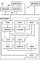
- FIG. 10 is a schematic block diagram showing an overview of the image processing apparatus 50 according to the second embodiment.
- symbol is attached
- the image processing apparatus 50 includes a display unit D, an operation unit C, an acquisition unit 1, an image processing unit 2, a display control unit 3, a designation unit 4, an identification unit 5, an extraction unit 6, and an angle calculation unit 7.
- the selection unit 8 and the storage unit 9 are included.
- the configuration of the angle calculation unit 7, the selection unit 8, and the storage unit 9 in the image processing apparatus 50 and the configuration associated therewith will be described.
- the second identification process has been completed.
- the extraction unit 6 has completed the process of associating the first area information with the voxel of the lump area and the process of associating the second area information with the voxel of the derived blood vessel region in the volume data.
- the angle calculation unit 7 acquires volume data after processing by the extraction unit 6. Next, the angle calculation unit 7 specifies a block region in the volume data based on the first region information. Further, the angle calculation unit 7 specifies a derived blood vessel region based on the second region information. The subsequent processing of the angle calculation unit 7 will be described in the first example and the second example.
- the angle calculation unit 7 specifies a boundary portion between the lump region and the derived blood vessel region.
- the angle calculation unit 7 performs contour extraction between the lump region and the derived blood vessel region.
- the angle calculation unit 7 specifies a portion where the contour of the lump region and the contour of the derived blood vessel region are continuous based on the boundary portion and the extracted contour.
- the angle calculation unit 7 specifies a portion where the contour of the lump region and the contour of the derived blood vessel region are continuous based on the boundary portion and the extracted contour.
- the angle calculation unit 7 specifies the base of the derived blood vessel region based on the information on the boundary portion between the lump region and the derived blood vessel region. Further, the angle calculation unit 7 specifies the protruding direction of the base by thinning processing or the like.
- the angle calculation unit 7 obtains the angle formed by the protruding direction of the base of the derived blood vessel and the lump. The angle calculation unit 7 specifies this angle as a departure angle of the derived blood vessel with respect to the lump.
- the angle calculation unit 7 specifies each boundary portion between the mass region and each derived blood vessel region.
- the angle calculation unit 7 specifies any voxel in the boundary portion as the starting end of the derived blood vessel region.
- the angle calculation unit 7 determines the point specified by the branch of the derived blood vessel region or other conditions (Modifications 1 to 4 or the like) or the point designated by the user via the operation unit C as the derived blood vessel region. Specify as end.
- the angle calculation unit 7 obtains a line segment connecting the specified start end and end. Furthermore, the angle calculation part 7 calculates
- the angle calculation unit 7 specifies each boundary portion between the mass region and each derived blood vessel region. Furthermore, the angle calculation unit 7 specifies any voxel at the boundary as a branch of the derived blood vessel region. Further, the angle calculation unit 7 acquires information on the center point CP obtained by the first identification process of the identification unit 5.
- the angle calculation unit 7 obtains a solid angle of a line connecting the branch and the center point CP in the volume data.
- the angle calculation unit 7 specifies this angle as a departure angle of the derived blood vessel with respect to the lump.
- the storage unit 9 stores display mode information corresponding to the separation angle. For example, the storage unit 9 divides and stores the separation angles into a plurality of ranges such as a first range, a second range, and an nth range. The storage unit 9 stores different display modes corresponding to the plurality of ranges. The different display modes are the same as the modes described in the first embodiment. That is, display color, transparency, and the like.
- the storage unit 9 includes a hard disk drive (HDD; Hard Disk Drive), a Flash SSD (Solid State Drive), a RAM SSD, and the like.
- the selection unit 8 receives from the angle calculation unit 7 information indicating each derived blood vessel and information on the separation angle of each derived blood vessel region associated with each derived blood vessel.
- the information indicating each derived blood vessel is, for example, coordinate information indicating each blood vessel.
- Another example of information indicating each derived blood vessel is second area information associated with the extraction unit 6 (see the first embodiment).
- the second region information is information (ID or the like) that is different for each derived blood vessel.
- the selection unit 8 acquires display mode information from the storage unit 9 on the basis of the information on the separation angle for each derived blood vessel region. The selection unit 8 associates the acquired display mode information with each corresponding derived blood vessel region.
- display mode information is associated with voxel information.
- the selection unit 8 may associate the display mode information with the second region information (ID or the like) that can identify each derived blood vessel.
- the selection unit 8 sends the processed volume data to the identification unit 5.
- you may match the display mode which is not allocated in the said process of the selection part 8 with the lump part area
- a display mode that can be clearly identified is preferably assigned to the block region for the display mode of each derived blood vessel region.
- the image processing unit 2 includes the coordinate information of voxels of each derived blood vessel region associated with the volume data, Based on the display mode information associated with the voxel, a preset display mode is assigned to the voxels in each region.
- the image processing unit 2 may assign the display mode information to the second region information (ID or the like) that can identify each derived blood vessel.
- the display mode set in advance is, for example, a display color. That is, the image processing unit 2 assigns red as the display color of the first derivative blood vessel region and assigns blue as the display color of the second derivative blood vessel region. In this way, the image processing unit 2 changes the display mode of the voxel group of each derived blood vessel region according to the associated display mode. Moreover, you may assign the different display mode which is not allocated to any voxel with respect to a block part area
- FIGS. 11 and 12 are flowcharts showing an outline of the operation of the image processing apparatus 50 according to the second embodiment.
- the calculation of the separation angle of the angle calculation unit 7 will be described based on the above “second example”.
- the angle calculation unit 7 acquires volume data after processing by the extraction unit 6.
- the angle calculation unit 7 specifies a block region in the volume data based on the first region information.
- the angle calculation unit 7 identifies each derived blood vessel region based on the second region information for each derived blood vessel.
- the angle calculation unit 7 specifies each boundary portion between the mass region and each derived blood vessel region.
- the angle calculation unit 7 specifies, for each identified derived blood vessel region, any voxel in the boundary portion as the starting end of the derived blood vessel region.
- the angle calculation unit 7 identifies a branch point of the derived blood vessel region as a terminal end of the derived blood vessel region.
- the angle calculation unit 7 obtains a line segment connecting the start end and the end specified in S23.
- the angle calculation unit 7 specifies an angle formed by the line segment obtained in S24 and the boundary between the mass region and the derived blood vessel region obtained in S23 as a separation angle.
- the angle calculation unit 7 determines whether the detachment angles have been obtained for all the derived blood vessels. As a result of the determination in S26, when there is a derived blood vessel for which the detachment angle has not been obtained (S26; No), the angle calculation unit 7 repeats the processes in S23 to S26.
- Step 27> As a result of the determination in S26, when it is determined that the detachment angles have been obtained for all the derived blood vessels (S26; Yes), the selection unit 8 determines, from the angle calculation unit 7, each derived blood vessel region associated with each derived blood vessel. Receive information on the angle of departure.
- the selection unit 8 acquires display mode information from the storage unit 9 based on the information on the separation angle acquired in S27 for each derived blood vessel region.
- the selection unit 8 associates the display mode information acquired in S28 for each corresponding derived blood vessel region.
- the image processing unit 2 determines whether there is an operation related to an image display instruction based on the volume data subjected to the above-described processing by the selection unit 8. The image processing unit 2 stands by until an operation related to an image display instruction is received (S26; No).
- the image processing unit 2 associates the identification information (coordinate information or second region information) of each derived blood vessel region associated with the volume data with the voxel. Based on the display mode information, a preset display mode is assigned to the voxels in each region.
- the image processing apparatus 50 acquires volume data including a lump part and blood vessels derived from the lump part as in the first embodiment. Further, the image processing apparatus 50 generates a volume rendering image from the volume data. Further, the image processing apparatus 50 receives an input of a designated point of the volume rendering image. Further, the image processing apparatus 50 identifies a voxel (or a group of voxels) that is assumed to be the center point of the lump in the volume data based on the designated point of the volume rendering image. Further, the image processing apparatus 50 expands the region from the center point as a starting point, and identifies the derived blood vessel region. In addition, the image processing apparatus 50 associates information indicating that it is a lump and a derived blood vessel with the identified voxel in the volume data.
- the image processing device 50 can show the mass and the derived blood vessel identified in the medical image, and can improve the visibility of these objects.
- the separation angle from the lump of each derived blood vessel region in the identified volume data is obtained.
- the selection part 8 acquires the display mode for every leaving angle from the memory
- the image processing unit 2 changes each derivative blood vessel region to a different display mode for each detachment angle. Moreover, you may assign a different display mode also about a lump part.
- the lump and the derived blood vessel can be further distinguished and clearly shown, and the visibility of these objects can be improved.
- the display mode is associated with each predetermined range of the separation angle.
- the angle calculation unit 7 first identifies one derived blood vessel region. This derived blood vessel region is defined as a first derived blood vessel region. Further, the angle calculation unit 7 obtains the detachment angle from the lump portion of the first derived blood vessel region in the same manner as in the second embodiment. This separation angle is defined as a first separation angle.
- the angle calculation unit 7 specifies another derived blood vessel region different from the first derived blood vessel region.
- This derived blood vessel region is defined as a second derived blood vessel region.
- the angle calculation unit 7 obtains the detachment angle from the lump portion of the second derived blood vessel region in the same manner as in the second embodiment.
- This separation angle is defined as a second separation angle.
- the separation angles of other derived blood vessel regions are obtained.
- the selection unit 8 receives the first separation angle and the second separation angle from the angle calculation unit 7. . . And the nth release angle. Further, the selection unit 8 compares the first separation angle with the second separation angle. Alternatively, the selection unit 8 obtains a difference between the first separation angle and the second separation angle. Furthermore, when the comparison result or the difference is within the set range, the selection unit 8 specifies the first derived blood vessel region as an inflow blood vessel for the mass. Further, the angle calculation unit 7 identifies the second blood vessel region as an outflow blood vessel. The selection unit 8 performs the same process for the detachment angles of other derived blood vessel regions.
- the selection unit 8 identifies one derived blood vessel region as an inflow blood vessel, and the other derived blood vessel. Identify the region as an outflow vessel. In other words, the selection unit 8 identifies one of the first and second derived blood vessel regions that are substantially opposite in direction as an inflow blood vessel connected to an artery and the other as an outflow blood vessel continuous to a vein. .
- the first derived blood vessel region and the second derived blood vessel region correspond to examples of “first blood vessel region” and “second blood vessel region”, respectively.
- the image processing unit 2 performs image processing for differentiating the display modes of each derived blood vessel region specified as an inflow blood vessel and each derived blood vessel region specified as an outflow blood vessel. For example, the image processing unit 2 sets the display color of the inflow blood vessel to red and the display color of the outflow blood vessel to blue.
- the image processing apparatus 50 can identify and display the mass and the derived blood vessel identified in the medical image, and can improve the visibility of these objects.
- the user can clearly identify the outflow blood vessel and the inflow blood vessel for AVM Nidus.
- Each unit that performs the process of Modification A corresponds to an example of a “contrast unit”.
- the image processing apparatus 60 includes a display unit D, an operation unit C, an acquisition unit 1, an image processing unit 2, a display control unit 3, a designation unit 4, an identification unit 5, an extraction unit 6, and a vector calculation unit 7A.
- a selection unit 8A and a storage unit 9A are included.
- the configuration of the vector calculation unit 7A, the selection unit 8A, and the storage unit 9 in the image processing apparatus 60 and the configuration associated therewith will be described.
- the second identification process has been completed.
- the extraction unit 6 has completed the process of associating the first area information with the voxel of the lump area and the process of associating the second area information with the voxel of the derived blood vessel region in the volume data.
- the identification unit 5 acquires the volume data processed by the extraction unit 6. Next, the identifying unit 5 identifies a bifurcation (boundary portion) between the mass region and the derived blood vessel region in the volume data based on the first region information and the second region information. The identification unit 5 performs identification processing of the branching unit for each derived blood vessel region.
- the vector calculation unit 7A specifies each derived blood vessel region in the volume data based on the second region information. Further, the vector calculation unit 7A obtains a vector in the traveling direction of the derived blood vessel region with respect to the bifurcation at each bifurcation identified by the identification unit 5. Alternatively, the angle between the line connecting the center point specified by the first identification process of the identification unit 5 and the branching portion and the traveling direction of the derived blood vessel region may be obtained as the departure angle.
- the storage unit 9 stores display mode information corresponding to the traveling direction.
- the storage unit 9 stores the traveling direction divided into a plurality of ranges such as a first range, a second range, and an nth range.
- the storage unit 9 stores different display modes corresponding to the plurality of ranges.
- the different display modes are the same as the modes described in the first embodiment. That is, display color, transparency, and the like.
- the selection unit 8A receives, from the vector calculation unit 7A, information on a vector in the traveling direction associated with each derived blood vessel (coordinate information of each blood vessel). Further, the selection unit 8A acquires display mode information from the storage unit 9 on the basis of the vector information in the traveling direction for each derived blood vessel region. The selection unit 8A associates the acquired display mode information with each corresponding derived blood vessel region. For example, display mode information is associated with voxel information. When the process of associating the display mode information with the voxels of each derived blood vessel region is completed, the selection unit 8A sends the processed volume data to the identification unit 5. In addition, you may match the display mode which is not allocated in the said process of the selection part 8A with respect to a block part area
- Image processing unit display mode changing process
- the processing for changing the display mode of the block region or the derived blood vessel region by the image processing unit 2 is the same as in the second embodiment.
- the image processing apparatus 60 acquires volume data including a lump part and blood vessels derived from the lump part as in the first embodiment. Further, the image processing device 60 generates a volume rendering image from the volume data. Further, the image processing device 60 receives input of designated points of the volume rendering image. Further, the image processing device 60 identifies a voxel (or a group of voxels) that is assumed to be the center point of the lump in the volume data based on the designated point of the volume rendering image. Further, the image processing device 60 expands the region from the center point as a starting point, and identifies up to the derived blood vessel region. In addition, the image processing device 60 associates information indicating that it is a lump and a derived blood vessel with the identified voxel in the volume data.
- the image processing device 60 can show the masses and derived blood vessels identified in the medical image, and can improve the visibility of these objects.
- vectors in the advancing direction from the mass portion of each derived blood vessel region in the identified volume data are obtained.
- an angle formed by the blood vessel traveling direction with respect to a line connecting the center point of the mass portion and the branching portion of the derived blood vessel region is obtained as the separation angle.
- the selection unit 8A acquires the display mode for each vector in the traveling direction from the storage unit 9, and assigns it to each derived blood vessel region.
- the image processing unit 2 changes each derivative blood vessel region to a different display mode for each detachment angle. Moreover, you may assign a different display mode also about a lump part.
- the inflow blood vessel and the outflow blood vessel can be clearly distinguished and shown. That is, in AVM, the inflow blood vessel and the outflow blood vessel may differ by approximately 180 °, and these can be clearly distinguished by obtaining a vector in the traveling direction.
- FIGS. 14 and 16 are schematic views conceptually showing the derived blood vessel identification processing according to the fourth embodiment.
- FIG. 15 is a first display example showing an overview of a list screen according to the fourth embodiment.
- FIG. 17 is a second display example showing an overview of a list screen according to the fourth embodiment. Note that description of portions common to any one of the first to third embodiments is omitted. In the following, only the processing contents after the first identification processing, the second identification processing, and the identification processing of each derived blood vessel (addition of second region information to each blood vessel, etc.) will be described.
- the extraction unit 6 receives the coordinate information of the voxel of the block identified by the identification unit 5 and the coordinate information of the voxel of the derived blood vessel.
- the extraction unit 6 according to the fourth embodiment further identifies each derived blood vessel based on the coordinate information. Further, as shown in FIG. 14, the extraction unit 6 adds identification information (BV1 to BV9 in FIG. 14) for each derived blood vessel.
- the block NI in FIGS. 14 to 17 is a schematic diagram illustrating an example of the AVM.
- the extraction unit 6 creates a list as shown in FIG. 15 for each of the derived blood vessels BV1 to BV9.
- the extraction unit 6 generates a composite image in which the created list and the image of the region of interest including the mass NI and the derived blood vessels BV1 to BV9 are combined.
- the synthesized image generated at this time is displayed with an ID assigned to each derived blood vessel (see FIG. 15).
- the IDs shown for each derived blood vessel in the composite image are displayed in a list for each derived blood vessel.
- the user can input whether the blood vessel is an inflow blood vessel or an outflow blood vessel with respect to the ID list of each derived blood vessel. For example, when the user performs an input operation of whether the blood vessel is an outflow blood vessel or an outflow blood vessel with respect to the input column of the ID list of each derived blood vessel, the extraction unit 6 receives the input, The image is displayed on the display unit D via the display control unit 3.
- the extraction unit 6 receives the voxel coordinate information of the block identified by the identification unit 5 and the voxel coordinate information for each derived blood vessel. Further, the extraction unit 6 receives information on whether it is an inflow blood vessel or an outflow blood vessel obtained for each derived blood vessel (hereinafter referred to as “blood flow information”).
- the extraction unit 6 identifies each derived blood vessel based on the coordinate information and the blood flow information. Further, the extraction unit 6 identifies, for each derived blood vessel, whether it is an inflow blood vessel or an outflow blood vessel based on blood flow information. Further, as shown in FIG. 16, the extraction unit 6 adds identification information (see BVI1 to BVI8 and BVO1 in FIG. 16) for each derived blood vessel.
- the extraction unit 6 creates a list as shown in FIG. 17 for the inflow blood vessels BVI1 to BVI8 and the outflow blood vessel BVO1.
- the extraction unit 6 generates a composite image in which the created list is combined with the image of the region of interest including the mass NI and the inflow blood vessels BVI1 to BVI8 and the outflow blood vessel BVO1.
- the synthesized image generated at this time is displayed with an ID assigned to each derived blood vessel (see FIG. 17).
- the IDs shown for each derived blood vessel in the composite image are displayed as a list for each inflow blood vessel BVI1 to BVI8 and outflow blood vessel BVO1.
- the user can edit the ID list of the inflow blood vessels BVI1 to BVI8 and the outflow blood vessel BVO1 in the composite image.
- the editing is an operation for changing, for example, inflow / outflow of the derived blood vessel by a user input operation on the list.
- the editing operation is performed when the user determines that the inflow blood vessel / outflow blood vessel discrimination determined by the selection unit or the like is incorrect. In that case, when the user designates the “edit button” shown in the list of the screen as shown in FIG. 17 by clicking and the like, the extracting unit 6 causes the inflow blood vessel / outflow blood vessel for each derived blood vessel displayed. It is possible to change and display the distinction.
- the structure which is possible may be sufficient.
- an editing operation may be possible by designating a region of each derived blood vessel image drawn in the composite image instead of the list.
- the extraction unit 6 is configured to identify the inflow blood vessel / outflow blood vessel for each derived blood vessel based on the blood flow information.
- the present invention is not limited to this, and the derived blood vessels may be grouped for each range of the detachment angle for each derived blood vessel as in the second embodiment.
- the extraction unit 6 includes a first group (0 ° ⁇ ⁇ ⁇ 90 °) with a separation angle of 0 ° or more and less than 90 °, and a second group (90 ° with a separation angle of 90 ° or more and less than 180 °).
- the grouping may be displayed as a large classification and the ID for each derived blood vessel may be displayed as a small classification in the list.
- the extraction unit 6 obtains information (value, etc.) on at least one of the blood vessel length, diameter, blood flow velocity, and contrast agent concentration for each derived blood vessel. Ask for. Further, the extraction unit 6 displays information of one or more items obtained in the list of composite images for each derived blood vessel ID.
- the extraction unit 6 obtains the length of each derived blood vessel based on the contour information or the coordinate information of the region for each derived blood vessel. The same applies when the diameter of the blood vessel is required.
- the length or diameter is obtained by using, for example, a core wire obtained for each derived blood vessel by thinning processing.
- the extraction unit 6 compares the voxel value information indicating the contrast agent with the voxel value of each voxel corresponding to the coordinate information of each derived blood vessel in the volume data, Determine the concentration of the contrast agent in the derived blood vessel.
- the information on the voxel value indicating the contrast agent is not a constant value, but includes a predetermined range of voxel values corresponding to the concentration of the contrast agent.
- the information on the voxel value is stored in advance. Therefore, the extraction unit 6 can determine the concentration of the contrast agent based on the voxel value of each voxel included in each derived blood vessel region.
- the extraction unit 6 obtains at least one item of information on the length of the blood vessel, the blood vessel diameter, the blood flow velocity, and the concentration information obtained for each derived blood vessel in the composite image list as illustrated in FIG. 15 or FIG. , Display corresponding to the ID of each derived blood vessel. For example, a length display field, a diameter display field, and a concentration display field are provided corresponding to the ID display field in the list.
- the length item, the vessel diameter item, and the concentration information item in the derived vessel list may be appropriately displayed according to the user's selection.
- the extraction unit 6 creates a composite image of an image showing the mass NI and each derived blood vessel and a list.
- the present invention is not limited to this, and a configuration in which a list is not created may be used.
- the display control unit 3 causes the display unit D to display the derived blood vessel specified in the selected display mode.
- the display image having such a configuration can be used for the purpose of highlighting the derived blood vessel to be treated first by the user in the image.
- the extraction unit 6 creates at least an identification ID for each derived blood vessel.
- the user can use any pointing device such as the operation unit C to point the pointer indicated in the image to one of the derived images. It is possible to move to a region indicating a blood vessel.
- the extraction unit 6 creates an image that displays the ID of the derived blood vessel using a pop-up or the like.
- the display control unit 3 displays the image on the display unit D.
- the extraction unit 6 when the extraction unit 6 acquires other information, the acquired information may be displayed together with the ID.
- the other information includes, for example, the above-described blood flow information of the derived blood vessel, the length of the derived blood vessel, the diameter of the derived blood vessel, and the concentration information of the contrast agent of the derived blood vessel.
- the extraction unit 6 obtains the contrast agent concentration of each derived blood vessel in the same manner as described above.
- the concentration of the contrast medium in the derived blood vessel at a predetermined time point represents the amount of blood flow received from the artery ar (see FIGS. 14 to 17).
- the extraction unit 6 creates an image that highlights the derived blood vessel having the highest concentration.
- the display control unit 3 displays the image on the display unit D.
- the display image having such a configuration can be used for the purpose of highlighting the derived blood vessel to be treated first by the user in the image.
- the image processing apparatus acquires volume data including a lump and blood vessels derived from the lump as in the first embodiment.
- the image processing apparatus generates a volume rendering image from the volume data.
- the image processing apparatus identifies a voxel (or a group of voxels) that is assumed to be the central point of the lump in the volume data based on the designated point of the volume rendering image.
- the image processing apparatus expands the area using the center point as a starting point, and identifies the derived blood vessel area.
- the image processing apparatus associates information indicating that it is a lump and a derived blood vessel with the identified voxel in the volume data.
- the image processing device 60 can show the masses and derived blood vessels identified in the medical image, and can improve the visibility of these objects.
- predetermined information is presented to the user by identifying each derived blood vessel.
- information related to the identified derived blood vessels is displayed as a list.
- an ID is displayed for each derived blood vessel in a morphological image or the like, and the display mode is changed according to the selection of the ID.
- information related to the identified derived blood vessel is displayed in a pop-up format in response to a mouse operation or the like.
- various types of information about the identified derived blood vessel can be provided to the user.
- the specific derived blood vessel can be highlighted and used for subsequent treatment.
- the control unit in the X-ray Angio apparatus displays a screen for selecting an image to be superimposed on the X-ray fluoroscopic image on the display unit of the apparatus. On the selection screen, the user selects volume data to be superimposed.
- Volume data includes 3D DSA data, 3D DA data, CTA data, MRA data, and the like.
- the X-ray Angio apparatus Upon receipt of the selection, the X-ray Angio apparatus makes a volume data acquisition request to the image processing apparatus 10 (or the image processing apparatus 50 or the image processing apparatus 60; the same applies hereinafter).
- the image processing apparatus 10 sends volume data associated with the patient ID or examination ID related to the acquisition request to the X-ray Angio apparatus.
- This volume data is data that has undergone display mode change processing according to any of the first to fourth embodiments described above or modifications thereof.
- the X-ray Angio apparatus may extract the lump region and the derived blood vessel region based on the coordinate information of the lump region and the coordinate information of the derived blood vessel region associated with the volume data. For example, the transparency other than the lump region and the derived blood vessel region is set as 100%.
- the X-ray Angio apparatus performs image processing based on the volume data from which the lump region and the derived blood vessel region are extracted by the control unit or the like.
- image processing include pixel value projection processing such as maximum value projection processing, minimum value projection processing, and average value projection processing, or MPR processing, volume rendering processing, surface rendering processing, and the like.
- the control unit of the X-ray Angio apparatus controls the imaging mechanism to collect data of the X-ray fluoroscopic image. This collection is performed continuously or intermittently during catheterization (embolization).
- the collected X-ray fluoroscopic image data is stored in the storage unit of the X-ray Angio apparatus.
- the control unit When collection of X-ray fluoroscopic images starts and a three-dimensional road map button is input by the user, the control unit reads out data of a two-dimensional image related to the specified angle.
- the display mode is different from that of the lump region and the derived blood vessel region and other portions. Alternatively, only the lump region and the derived blood vessel region may be extracted and displayed.
- this image will be described as a road map image.
- the image composition unit of the X-ray Angio apparatus synthesizes both images by aligning the positions so that the anatomical positions of the road map image and the X-ray fluoroscopic image substantially coincide.
- the image synthesizing unit performs position alignment according to the positional deviation amount calculated in advance by the positional deviation amount calculation unit.
- composite image data is generated.
- This composite image is displayed on the display unit.
- the composite image may include a guide wire region (or catheter region) derived from the X-ray fluoroscopic image.
- the display unit corresponds to an example of a “composite image display unit”.
- the composite image is configured so that the display mode is different from that of the lump area and the derived blood vessel area and other parts, so the catheter has entered the target blood vessel or has entered another blood vessel. Can be easily determined.
- the imaging angle of the C arm of the imaging mechanism of the X-ray Angio apparatus may be changed during the collection of the X-ray fluoroscopic image.
- road map image data that substantially matches the changed shooting angle is generated based on the volume data.
- a composite image of the road map image and the fluoroscopic image is generated and displayed by the control unit or the like. Even when the imaging angle of the C-arm is changed in this way, according to the present embodiment, the road map image and the X-ray fluoroscopic image corresponding to the changed imaging angle can be combined and displayed.
- the medical image processing system acquires volume data including a clot and blood vessels derived from the clot as in the first embodiment.
- the image processing apparatus generates a volume rendering image from the volume data.
- the image processing apparatus identifies a voxel (or a group of voxels) that is assumed to be the central point of the lump in the volume data based on the designated point of the volume rendering image.
- the image processing apparatus expands the area using the center point as a starting point, and identifies the derived blood vessel area.
- the image processing apparatus associates information indicating that it is a lump and a derived blood vessel with the identified voxel in the volume data.
- the image processing apparatus can show the masses and derived blood vessels identified in the medical image, and can improve the visibility of these objects.
- the image processing apparatuses according to the first to fifth embodiments and the modifications thereof can be identified even if the shape of the volume data is complicated. Therefore, the image processing apparatus can identify and display the mass and the derived blood vessel identified in the medical image, and can improve the visibility of these objects.
- the image acquisition device and the medical image processing device may be an integrated device.
- scanning is performed to acquire detection data indicating the state of a three-dimensional region including a lump and a derived blood vessel in the subject by scanning the subject.
- a volume data generation unit that generates volume data based on the detected data is included.
- the image acquisition device and the display unit of the image processing device 10 or the image processing device 50 are common. An apparatus in which such an image acquisition apparatus and a medical image processing apparatus are integrated corresponds to an example of a “medical image diagnostic apparatus”.
Landscapes
- Health & Medical Sciences (AREA)
- Life Sciences & Earth Sciences (AREA)
- Engineering & Computer Science (AREA)
- Medical Informatics (AREA)
- Physics & Mathematics (AREA)
- General Health & Medical Sciences (AREA)
- Public Health (AREA)
- Pathology (AREA)
- Biomedical Technology (AREA)
- Surgery (AREA)
- Heart & Thoracic Surgery (AREA)
- Molecular Biology (AREA)
- Animal Behavior & Ethology (AREA)
- Biophysics (AREA)
- Veterinary Medicine (AREA)
- Nuclear Medicine, Radiotherapy & Molecular Imaging (AREA)
- Radiology & Medical Imaging (AREA)
- Computer Vision & Pattern Recognition (AREA)
- High Energy & Nuclear Physics (AREA)
- Optics & Photonics (AREA)
- Theoretical Computer Science (AREA)
- Physiology (AREA)
- General Physics & Mathematics (AREA)
- Oral & Maxillofacial Surgery (AREA)
- Dentistry (AREA)
- Hematology (AREA)
- Psychiatry (AREA)
- Pulmonology (AREA)
- Cardiology (AREA)
- Artificial Intelligence (AREA)
- Vascular Medicine (AREA)
- Signal Processing (AREA)
- Human Computer Interaction (AREA)
- Quality & Reliability (AREA)
- Data Mining & Analysis (AREA)
- Databases & Information Systems (AREA)
- Epidemiology (AREA)
- Primary Health Care (AREA)
- Apparatus For Radiation Diagnosis (AREA)
- Magnetic Resonance Imaging Apparatus (AREA)
Abstract
実施形態にかかる医用画像処理装置は、医用画像において患部に流入または流出する血管の視認性を向上させることを可能とする。医用画像処理装置は、取得部、同定部、識別部および表示制御部を備える。取得部は、被検体内における、塊部および当該塊部から派生する複数の血管を含む3次元領域の状態を示すボリュームデータを取得する。同定部は、ボリュームデータにおける塊部および当該塊部から派生する複数の血管に相当する領域を特定する。また同定部は、当該特定した領域を、関心領域として同定する。識別部は、同定された関心領域において、塊部および複数の血管それぞれを識別する。表示制御部は、識別された塊部および複数の血管それぞれのうち、少なくともいずれか1つの表示態様を変更する。
Description
この発明の実施形態は医用画像処理装置に関する。
X線診断装置などを使用した医用画像技術により、インターベンション治療(血管内治療)が行われている。例えば、X線診断装置により被検体の体内画像を生成して表示しながら、医師等によりインターベンション治療が行われる。
すなわち医師等は、表示された画像における血管を参照しながら、被検体に挿入されたカテーテルを被検体内の所定部位まで導く。動脈瘤の治療法の一例において、医師は、足の付け根等からガイドワイヤを挿入する。また医師はガイドワイヤに沿ってカテーテルを用いて患部まで導く。さらに医師等は、画像を参照しながら、所定部位の塞栓を行う。塞栓は、例えば、カテーテルの先端からコイルのような閉塞物質を所定部位に留置することにより行われる。なお、塞栓する対象の部位は、動脈瘤、AVM(動静脈奇形;Arteriovenous malformation)への流入血管、または腫瘍への流入血管等である。
この塞栓術により流入血管への血流が妨げられる。AVMの治療において、ナイダス(nidus)に流入する血管を閉塞することにより、ナイダスへの血流が遮断される。このような塞栓術により、血液が流れる方向を適正化することが可能である。また、動脈瘤に対しては、コイルの留置により動脈瘤内で血液を凝固させて治療する。また、腫瘍の治療の場合、腫瘍へ流れる栄養血管に流入する血管を閉塞することにより、腫瘍への血流を遮断することが可能である。
上述の通り、医師は医用画像を参照しながら所定部位への流入血管を閉塞する塞栓術を行う。そのため、医師にとって流入血管およびその周辺領域を円滑に把握できることが望ましい。この点、当該医用画像において流入血管の部分の把握を容易にするための技術が提案されていた。
しかしながら、腫瘍への栄養血管、AVMへの流入血管、動脈瘤のネックあるいはドームからの流出血管等は、その形状が複雑であるため、同定することが困難である。したがって、医用画像診断装置において当該部分の血管の形状を画像の閲覧者に円滑に把握させるような医用画像を生成することは困難であった。
この実施形態は、医用画像において患部に流入または流出する血管の視認性を向上させることが可能な医用画像処理装置を提供することを目的とする。
医用画像処理装置は、取得部、同定部、識別部および表示制御部を備える。取得部は、被検体内における、塊部および当該塊部から派生する複数の血管を含む3次元領域の状態を示すボリュームデータを取得する。同定部は、ボリュームデータにおける塊部および当該塊部から派生する複数の血管に相当する領域を特定する。また同定部は、当該特定した領域を、関心領域として同定する。識別部は、同定された関心領域において、塊部および複数の血管それぞれを識別する。表示制御部は、識別された塊部および複数の血管それぞれのうち、少なくともいずれか1つの表示態様を変更する。
図1~図17を参照して、第1実施形態~第5実施形態にかかる医用画像処理装置または画像取得装置について説明する。
[第1実施形態]
(医用画像処理システム)
第1実施形態にかかる医用画像処理システムにつき、図1を参照して説明する。図1は、第1実施形態にかかる医用画像処理システムの概略構成を示すブロック図である。図1に示すように、医用画像処理システムは、画像処理装置10、画像取得装置20A~画像取得装置20C…画像取得装置20nおよび画像保管装置30を含んで構成されている。これらの各装置はネットワークNを介して相互にデータ通信が可能に接続されている。なお、図1においては一例として画像取得装置20A、画像取得装置20B、画像取得装置20Cおよび画像保管装置30がネットワークに接続されているが、各装置の数は任意に設定することが可能である。
(医用画像処理システム)
第1実施形態にかかる医用画像処理システムにつき、図1を参照して説明する。図1は、第1実施形態にかかる医用画像処理システムの概略構成を示すブロック図である。図1に示すように、医用画像処理システムは、画像処理装置10、画像取得装置20A~画像取得装置20C…画像取得装置20nおよび画像保管装置30を含んで構成されている。これらの各装置はネットワークNを介して相互にデータ通信が可能に接続されている。なお、図1においては一例として画像取得装置20A、画像取得装置20B、画像取得装置20Cおよび画像保管装置30がネットワークに接続されているが、各装置の数は任意に設定することが可能である。
例えば、画像処理装置10と複数の画像取得装置20A、画像取得装置20B 、画像取得装置20C…画像取得装置20nは、ネットワークを介して、複数の断層像あるいはボリュームデータを送受信することが可能である。同様に画像保管装置30は、画像取得装置20A、画像取得装置20B、画像取得装置20C…画像取得装置20nにおいて生成された断層像あるいはボリュームデータを、付帯情報とともに記憶する。また、画像保管装置30は、画像処理装置10からの求めに応じ、記憶しているボリュームデータ等を画像処理装置10に送る。
なお、以下の例において、画像取得装置20A等は被検体の体内組織の情報の収集等を行う医用画像の画像取得装置として説明される。例えば、X線画像取得装置(X線Angio装置)、X線CT画像取得装置、MRI画像取得装置、超音波画像取得装置等である。
また、画像保管装置30は、例えばPACS(Picture Archiving and Communication System)によるものである。例えば画像保管装置30は、画像データベースを有する画像管理装置である。画像管理装置はプログラムにより、画像データベースの医用画像データを管理する。他の例として画像保管装置30はネットワークアタッチドストレージ(NAS;Network Attached Storage)等の医用画像データを記憶するファイルサーバであってもよい。
(画像処理装置の概要)
第1実施形態にかかる画像処理装置10について、医用画像ワークステーションを一例として説明する。第1実施形態は、画像処理装置10が医用画像にかかるボリュームデータを取得する。また、画像処理装置10は、そのボリュームデータにおける、塊部および塊部から派生する血管を特定し、特定した領域を関心領域として同定する。なお、第1実施形態の画像処理装置10は、あらかじめ画像取得装置20A~画像取得装置20Cにより取得され、画像保管装置30に保管されたボリュームデータを取得する構成である。ただし、画像処理装置10の構成の他の例として、後述の第2実施形態のように、被検体の体内組織の情報の収集、再構成処理、ボリュームデータの生成を行うものであってもよい。
第1実施形態にかかる画像処理装置10について、医用画像ワークステーションを一例として説明する。第1実施形態は、画像処理装置10が医用画像にかかるボリュームデータを取得する。また、画像処理装置10は、そのボリュームデータにおける、塊部および塊部から派生する血管を特定し、特定した領域を関心領域として同定する。なお、第1実施形態の画像処理装置10は、あらかじめ画像取得装置20A~画像取得装置20Cにより取得され、画像保管装置30に保管されたボリュームデータを取得する構成である。ただし、画像処理装置10の構成の他の例として、後述の第2実施形態のように、被検体の体内組織の情報の収集、再構成処理、ボリュームデータの生成を行うものであってもよい。
図1に示すように画像処理装置10は、表示部D、操作部C、取得部1、画像処理部2、表示制御部3、指定部4、同定部5、抽出部6を含んで構成される。以下、画像処理装置10における各部の構成について説明する。
(表示部)
表示部Dは、CRT(Cathode Ray Tube)ディスプレイや、LCD(Liquid Crystal Display)、有機EL(OELD;Organic Electro-Luminescence Display)または、FED(Field Emission Display)等の任意の形態の表示デバイスによって構成される。表示部Dは、表示制御部3の制御を受けて各種の操作画面、設定画面や医用画像を表示する。
表示部Dは、CRT(Cathode Ray Tube)ディスプレイや、LCD(Liquid Crystal Display)、有機EL(OELD;Organic Electro-Luminescence Display)または、FED(Field Emission Display)等の任意の形態の表示デバイスによって構成される。表示部Dは、表示制御部3の制御を受けて各種の操作画面、設定画面や医用画像を表示する。
(操作部)
操作部Cは、キーボード、マウス、トラックボール、ジョイスティック、コントロールパネル等の任意の形態の操作デバイスや入力デバイスによって構成される。また、タッチパネル等、操作部Cの一部と表示部Dを同一のデバイスにより構成することも可能である。図示しない主制御部は、実施された操作に基づいて操作部Cが出力する操作信号を受けて、この操作内容に対応する上記各部制御の演算を実行する。
操作部Cは、キーボード、マウス、トラックボール、ジョイスティック、コントロールパネル等の任意の形態の操作デバイスや入力デバイスによって構成される。また、タッチパネル等、操作部Cの一部と表示部Dを同一のデバイスにより構成することも可能である。図示しない主制御部は、実施された操作に基づいて操作部Cが出力する操作信号を受けて、この操作内容に対応する上記各部制御の演算を実行する。
(取得部)
取得部1は、操作部Cからの操作信号を受け、画像保管装置30に対するボリュームデータの取得要求を実行する。例えば画像処理装置10において、ユーザが操作部Cを介して、患者IDまたは検査IDを入力してボリュームデータの取得要求にかかる操作が行われる。当該操作が行われると、取得部1は画像保管装置30に対し、操作に応じて入力されたIDに基づくボリュームデータの取得要求を行う。
取得部1は、操作部Cからの操作信号を受け、画像保管装置30に対するボリュームデータの取得要求を実行する。例えば画像処理装置10において、ユーザが操作部Cを介して、患者IDまたは検査IDを入力してボリュームデータの取得要求にかかる操作が行われる。当該操作が行われると、取得部1は画像保管装置30に対し、操作に応じて入力されたIDに基づくボリュームデータの取得要求を行う。
画像保管装置30は、当該取得要求にしたがって、ボリュームデータの検索を行う。さらに画像保管装置30は、ID等応じたボリュームデータを読出し、画像処理装置10に送る。取得部1は、画像保管装置30から受けたボリュームデータを少なくとも一時的に記憶する。この取得部1には、RAM(Random Access Memory)や、HDD(Hard Disk Drive)またはSSD(Solid State Drive)等、任意の記憶媒体が含まれる。なお、当該ボリュームデータを記憶するのは、他の記憶装置であってもよい。
また、後述する第2の同定処理、抽出処理等の各種処理後のボリュームデータは同定部5に記憶されるが、これに限らず取得部1が記憶してもよい。また、取得部1は、2次元画像処理におけるボリュームレンダリング画像を記憶してもよい。また、取得部1は、ボリュームデータに対する2次元画像処理(ボリュームレンダリング処理、サーフェスレンダリング処理等)の画像処理条件を記憶する。
(画像処理部)
画像処理部2は、操作部Cを介した画像処理操作により、ボリュームデータに対して2次元画像の生成にかかる画像処理を行う。例えば、ユーザがボリュームデータに基づくボリュームレンダリング(VR;Volume Rendering)画像を生成する操作を行うと、画像処理部2は、当該操作にかかる指示を受ける。画像処理部2は当該指示を受け、表示制御部3を介してボリュームレンダリング処理にかかる各種パラメータを設定するための設定画面を表示部Dに表示させる。各種パラメータには、例えばボリュームレンダリング処理にかかる視線方向の設定情報が含まれる。また各種パラメータには、ボリュームデータにおける各ボクセルのボクセル値ごとの透明度の設定情報が含まれる。また、各種パラメータには、ボリュームレンダリング画像におけるWL(Window Level)およびWW(Window Width)の設定情報が含まれる。
画像処理部2は、操作部Cを介した画像処理操作により、ボリュームデータに対して2次元画像の生成にかかる画像処理を行う。例えば、ユーザがボリュームデータに基づくボリュームレンダリング(VR;Volume Rendering)画像を生成する操作を行うと、画像処理部2は、当該操作にかかる指示を受ける。画像処理部2は当該指示を受け、表示制御部3を介してボリュームレンダリング処理にかかる各種パラメータを設定するための設定画面を表示部Dに表示させる。各種パラメータには、例えばボリュームレンダリング処理にかかる視線方向の設定情報が含まれる。また各種パラメータには、ボリュームデータにおける各ボクセルのボクセル値ごとの透明度の設定情報が含まれる。また、各種パラメータには、ボリュームレンダリング画像におけるWL(Window Level)およびWW(Window Width)の設定情報が含まれる。
上記設定画面において、ユーザが操作部Cを介して各種パラメータを設定すると、当該各種パラメータが画像処理部2に送られる。画像処理部2は、各種パラメータに基づき、例えばボリュームレンダリング画像を生成するための処理を実行する。例えば画像処理部2は、設定された視線方向にしたがって、ボリュームレンダリング処理における光源の位置と画像の投影方向を定める。また、画像処理部2は、設定された各ボクセルのボクセル値ごとの透明度にしたがって、各ボクセルの透明度を設定する。
このようにして画像処理部2は、ボリュームデータにボリュームレンダリング処理を施して2次元画像を生成する。なお、画像処理部2としては、ユーザが設定した各種パラメータに基づいてボリュームレンダリング画像を生成する構成に限られない。例えば画像処理部2は、少なくとも一部のパラメータとしてあらかじめ設定されたデータを用いてボリュームレンダリング画像を生成してもよい。なお、下記実施形態にかかる処理が行われる場合、上記いずれかの処理によって生成される2次元画像には、例えば動脈瘤と動脈瘤からの流出血管、AVM(動静脈奇形;Arteriovenous malformation)のナイダスとナイダスへの流入血管、または腫瘍と腫瘍への流入血管等の表面形状が含まれているものとする。
画像処理部2は、生成したボリュームレンダリング画像を表示制御部3に送る。また画像処理部2は、ボリュームレンダリング処理に用いた視線方向等のパラメータを、対象のボリュームデータと対応付けて記憶する。なお、上記において画像処理部2は、ボリュームレンダリング画像を生成する構成であるが、これに限られない。例えば画像処理部2は、サーフェスレンダリング画像、MIP(Maximum Intensity Projection)画像、MinIP(Minimum Intensity Projection)画像等を生成してもよい。
(表示制御部)
表示制御部3は、上記の通り画像処理部2により生成される2次元画像の生成にかかる各種パラメータの設定画面を生成し、表示部Dに表示させる制御を行う。また表示制御部3は、画像処理部2により生成されたボリュームレンダリング画像を表示部Dに表示させる制御を行う。また表示制御部3は、抽出された血管領域、または塊部領域および血管領域を含む医用画像を表示部Dに表示させる制御を行う。なお、血管領域等の抽出については後述する。また、表示制御部3は血管領域等の表示態様にかかる設定画面を表示部Dに表示させる制御を行う。なお、以下記載される各画像については、特に記載しない限り、表示制御部3による表示制御が行われた結果、表示部Dに表示されたものとして説明する。
表示制御部3は、上記の通り画像処理部2により生成される2次元画像の生成にかかる各種パラメータの設定画面を生成し、表示部Dに表示させる制御を行う。また表示制御部3は、画像処理部2により生成されたボリュームレンダリング画像を表示部Dに表示させる制御を行う。また表示制御部3は、抽出された血管領域、または塊部領域および血管領域を含む医用画像を表示部Dに表示させる制御を行う。なお、血管領域等の抽出については後述する。また、表示制御部3は血管領域等の表示態様にかかる設定画面を表示部Dに表示させる制御を行う。なお、以下記載される各画像については、特に記載しない限り、表示制御部3による表示制御が行われた結果、表示部Dに表示されたものとして説明する。
表示制御部3の制御例として、ボリュームレンダリング画像を表示部Dに表示させる制御を行う。このボリュームレンダリング画像が表示されているとき、画像処理装置10は、次に説明する指定点の指定操作を受け付け可能である。なお本実施形態において、ボリュームレンダリング画像には、塊部が示されているものとして以下の説明を記載する。塊部は、例えばAVMにおけるナイダス、動脈瘤、腫瘍等である。また、ボリュームレンダリング画像には、当該塊部に連なる血管、または当該塊部から派生する血管等が示されているものとして以下の説明を記載する。また以下において、被検体内の組織のうち、ナイダス、動脈瘤または腫瘍等を示す塊部を、単に「塊部」と記載することがある。また、当該塊部に連なる血管または当該塊部から派生する血管について、単に「派生血管」と記載することがある。
さらに表示制御部3は、ボリュームレンダリング画像における塊部の一部、例えば画像における塊部を示す範囲のうちの一点を指定することを促すメッセージを表示部Dに表示させてもよい。また、表示制御部3はボリュームレンダリング画像内に塊部を示す領域が含まれているかについて判断する構成であってもよい。
例えば表示制御部3は血管や塊部を示す画素値の範囲を記憶している。また表示制御部3は、塊部におけるその他の部位(骨等)に対する相対的大きさの情報を記憶している。表示制御部3は、ボリュームレンダリング画像における、塊部等を示す画素値を有するピクセルが占める範囲を、記憶している情報に基づいて求める。また。表示制御部3は、その範囲の大きさをピクセル数等に基づいて求める。表示制御部3は、記憶している塊部の大きさと求めた範囲の大きさとを対比する。対比の結果、塊部の大きさが記憶している大きさまで至らない場合、表示制御部3は、表示されたボリュームレンダリング画像に塊部が含まれていないことを示す警告等を、表示部Dに表示させてもよい。
(指定部)
指定部4は、表示部Dにボリュームレンダリング画像が表示されているとき、操作部Cを介した指定点の指定操作があると、その操作を受け付ける。この指定点は、後述の同定部5による中心点の同定処理に用いられる。例えばユーザが操作部Cを介して、ボリュームレンダリング画像に示された塊部の中心位置に相当する位置を指定すると、指定部4が画像中の当該指定位置に対応する座標を、指定点として記憶する。さらにユーザにより当該指定点を確定する操作が実行されると、指定部4は指定点の座標情報を同定部5に送る。
指定部4は、表示部Dにボリュームレンダリング画像が表示されているとき、操作部Cを介した指定点の指定操作があると、その操作を受け付ける。この指定点は、後述の同定部5による中心点の同定処理に用いられる。例えばユーザが操作部Cを介して、ボリュームレンダリング画像に示された塊部の中心位置に相当する位置を指定すると、指定部4が画像中の当該指定位置に対応する座標を、指定点として記憶する。さらにユーザにより当該指定点を確定する操作が実行されると、指定部4は指定点の座標情報を同定部5に送る。
なお、上記においては指定部4がユーザにより指定された画像中の位置を指定点として記憶する構成であるが、本実施形態はこれに限られない。例えば、上述のように表示制御部3が画像中の塊部等の範囲を特定する構成の場合、指定部4はその画像中の塊部を示す領域の座標、またはその輪郭の座標を取得する。また指定部4は、表示制御部3から受けた輪郭を示す部分の情報に基づき、その中心点に相当する座標を求める。指定部4は求めた中心点の座標を指定点として記憶する構成であってもよい。またこの構成において当該指定点は、ユーザが操作部Cによって移動することにより編集可能であってもよい。
(同定部)
次に、同定部について図1~図5を参照して説明する。図2は、ボリュームデータを概念的に示す概略図である。また、図3は同定部5による指定点に基づく中心点の同定を概念的に示す概略図である。また、図4Aおよび図4Bは、同定部5による領域拡張を概念的に示す概略図である。また図5は、リージョングローイングステップ数と、全近傍ボクセル数に対する対象部位ボクセルの割合との対応関係の概略を示すグラフである。以下においては、中心点の同定処理である第1の同定処理と、塊部および派生血管の同定処理である第2の同定処理とに分けて説明する。なお、以下に説明する中心点とは、実際の塊部の中心であってもよいが、必ずしも当該中心を示すものではない。すなわち本実施形態においては第1の同定処理において同定されたボリュームデータ内の点を説明の便宜上「中心点」または「指定点」として説明する。
次に、同定部について図1~図5を参照して説明する。図2は、ボリュームデータを概念的に示す概略図である。また、図3は同定部5による指定点に基づく中心点の同定を概念的に示す概略図である。また、図4Aおよび図4Bは、同定部5による領域拡張を概念的に示す概略図である。また図5は、リージョングローイングステップ数と、全近傍ボクセル数に対する対象部位ボクセルの割合との対応関係の概略を示すグラフである。以下においては、中心点の同定処理である第1の同定処理と、塊部および派生血管の同定処理である第2の同定処理とに分けて説明する。なお、以下に説明する中心点とは、実際の塊部の中心であってもよいが、必ずしも当該中心を示すものではない。すなわち本実施形態においては第1の同定処理において同定されたボリュームデータ内の点を説明の便宜上「中心点」または「指定点」として説明する。
(第1の同定処理)
図2を参照して第1の同定処理について説明する。同定部5は、指定部4からボリュームレンダリング画像における指定点の座標にかかる情報を受ける。それに応じて同定部5は、当該指定点の指定にかかるボリュームレンダリング画像を取得する。また同定部5は、そのボリュームレンダリング画像にかかるボリュームデータを取得部1から取得する。さらに同定部5は、取得部1に記憶されたボリュームデータに対する2次元画像処理(ボリュームレンダリング処理、サーフェスレンダリング処理等)の画像処理条件を取得する。
図2を参照して第1の同定処理について説明する。同定部5は、指定部4からボリュームレンダリング画像における指定点の座標にかかる情報を受ける。それに応じて同定部5は、当該指定点の指定にかかるボリュームレンダリング画像を取得する。また同定部5は、そのボリュームレンダリング画像にかかるボリュームデータを取得部1から取得する。さらに同定部5は、取得部1に記憶されたボリュームデータに対する2次元画像処理(ボリュームレンダリング処理、サーフェスレンダリング処理等)の画像処理条件を取得する。
同定部5は、取得した画像処理条件と、ボリュームレンダリング画像およびボリュームデータそれぞれの座標等に基づき、ボリュームレンダリング画像とボリュームデータとの対応関係を求める。すなわち同定部5は、ボリュームレンダリング画像の各ピクセルそれぞれが、ボリュームデータにおけるどのボクセルに対応するかを求める。
次に、同定部5は、ボリュームレンダリング画像中の指定点の座標とボリュームデータのボクセルの座標との対応関係から、ボリュームデータにおける指定点の座標を求める。また同定部5は、取得部1から取得したボリュームレンダリング画像の画像処理条件から、ボリュームレンダリング処理を行ったときの、ボリュームデータに対する画像の視線方向(投影方向)を抽出する。なお、画像処理条件にボリュームレンダリング画像の視線方向の情報が含まれていない場合、ボリュームレンダリング画像の表示内容と、ボリュームデータとの対応関係に基づいて、同定部5により視線方向が求められる。
次に、同定部5はボリュームデータにおける指定点を視線方向に通る軌跡RTを求める。この処理について図2および図3を参照して説明する。図2は、ボリュームデータを3次元的に示している。図3は図2のZ軸方向に直交するX-Y断面を示している。すなわち、Y軸方向に直交し、X軸およびZ軸方向に沿ったボリュームレンダリング画像に対して、図2の断面は直交している。言い換えれば、ボリュームレンダリング画像を投影方向から見る方向(Y方向)をボリュームデータの正面とすると、図3は、ボリュームデータを底面から上面に向かって、または上面から底面に向かって見た場合の概念図である。
図3に示すように、同定部5はボリュームデータVDにおいて指定点DPを視線方向(図2の左右方向)に通る軌跡RTを求める。次に同定部5は、軌跡RTが通過するボクセルのボクセル値をそのボクセルの座標とともにそれぞれ抽出する。また同定部5は、あらかじめ記憶している所定のボクセル値の設定情報を読み出す。この設定情報とは、塊部を示すボクセル値および血管を示すボクセル値である。さらに、同定部5は読み出したボクセル値の設定情報と、軌跡RTが通過する各ボクセルのボクセル値とを対比する。この対比によって、同定部5は、軌跡RT上において塊部に相当する領域および血管に相当する領域と、それ以外の領域とを判別する。
なお、設定情報にかかるボクセル値は所定の範囲を有していてもよい。また、ここで判別された塊部に相当する領域および血管に相当する領域は、「関心領域」の一例に該当し、それ以外の領域は「その他の部分」の一例に該当する。また、上記設定情報は「塊部または血管に相当するボクセルを同定するための閾値」の一例に該当する。また、この時点では血管に相当する領域が、塊部からの派生血管であるかについては判別されていない。
なお、設定情報にかかるボクセル値は所定の範囲を有していてもよい。また、ここで判別された塊部に相当する領域および血管に相当する領域は、「関心領域」の一例に該当し、それ以外の領域は「その他の部分」の一例に該当する。また、上記設定情報は「塊部または血管に相当するボクセルを同定するための閾値」の一例に該当する。また、この時点では血管に相当する領域が、塊部からの派生血管であるかについては判別されていない。
対比の結果、同定部5は軌跡RTが通過するボクセルのうち、設定情報に対応するボクセル値を有するボクセルの座標を求める。さらに同定部5は、軌跡RT上において設定情報に対応するボクセルが連続している部分の幅L1,L2,L3…Lnを求める。同定部5は、求められた幅L1,L2,L3…Lnのうち、最も広い幅を塊部と判断する。図2においては幅L1が最も広い幅である。さらに同定部5は、塊部と判断された最も広い幅L1の中間位置の座標を、L1の始端の座標と終端の座標とに基づいて求める(L1/2)。このような処理によって同定部5は、求めた中間位置を塊部の中心点(図3;符号CP参照)として同定する。
なお、同定部5は求めた最も広い幅L1と、その他の塊部におけるその他の部位(骨等)に対する相対的な大きさを求めることにより、塊部の相対的な大きさが所定の値まで至らない場合には、再度指定点の入力を促す表示制御を表示制御部3に行わせてもよい。あるいは同定部5は塊部が含まれていないことを示す警告等を表示させてもよい。
(第2の同定処理)
次に、同定部5による塊部および派生血管の同定処理である第2の同定処理について図3、図4A、図4Bおよび図5を参照して説明する。なお、第2の同定処理として、リージョングローイング法により塊部の領域を段階的に拡張して派生血管まで到達する例を説明する。また、リージョングローイングの1ステップにより領域拡張される範囲として、第1の同定処理において同定された中心点CPを中心にX軸、Y軸およびZ軸に沿って前後2ボクセル拡張していく例について説明する。すなわち以下の説明において同定部5は、X軸で3ボクセル、Y軸で3ボクセルおよびZ軸で3ボクセルの3×3×3の27ボクセルから、拡張する中心の1ボクセルを減算した近傍の26ボクセルの領域拡張をする。
次に、同定部5による塊部および派生血管の同定処理である第2の同定処理について図3、図4A、図4Bおよび図5を参照して説明する。なお、第2の同定処理として、リージョングローイング法により塊部の領域を段階的に拡張して派生血管まで到達する例を説明する。また、リージョングローイングの1ステップにより領域拡張される範囲として、第1の同定処理において同定された中心点CPを中心にX軸、Y軸およびZ軸に沿って前後2ボクセル拡張していく例について説明する。すなわち以下の説明において同定部5は、X軸で3ボクセル、Y軸で3ボクセルおよびZ軸で3ボクセルの3×3×3の27ボクセルから、拡張する中心の1ボクセルを減算した近傍の26ボクセルの領域拡張をする。
図4Aは、リージョングローイングの第1ステップにおいて第1の同定処理において同定された中心点CPを中心に26近傍のボクセルを拡張する処理を概念的に示している。図4Bは上段において中心点CPを含むX軸、Y軸およびZ軸ごとの拡張範囲を概念的に示している。さらに図4Bは下段において、リージョングローイングの全ステップ数nの半分のステップ数に到達した段階の塊部または派生血管と、それ以外の部分の比率を示している。なお、ここで説明したリージョングローイングの全ステップ数nとは、結果的に派生血管の同定が完了した時点のステップ数を示すものであって、あらかじめ設定されている必要はない。ただし、後述する変形例のようにあらかじめリージョングローイングの全ステップ数をあらかじめ設定する構成も含む。また、図4Aおよび図4Bにおけるハッチング部分は塊部および派生血管のいずれかを示している。
第2の同定処理においても、同定部5は、第1の同定処理において読み出したボクセル値の設定情報を用いる。つまり設定情報は、塊部を示すボクセル値および血管を示すボクセル値である。リージョングローイングにおいて、同定部5は当該ボクセル値の設定情報と、設定された26近傍の各ボクセルのボクセル値とを対比する。リージョングローイングによる塊部領域および派生血管領域の同定処理の流れは、概ね次の通りである。
同定部5は、リージョングローイングにより、中心点CPから上記対比により塊部に属する連結領域を順次取り込みながら領域拡張を行う。同定部5は、領域の連結性を、開始点である中心点CPを中心として設定情報の範囲内にあるか否かで判定する。
なお、同定部5は設定情報と近傍ボクセルのボクセル値とを対比して領域拡張をするだけに限られない。例えば、同定部5は、領域拡張条件である設定情報を、領域拡張処理の過程における周囲のボクセルのボクセル値の変化の状態に応じて変更することが可能である。具体的な一例として、同定部5は領域拡張の処理(探索処理)の過程において周囲のボクセルのボクセル値の変化を示す数値を求める。さらに同定部5は、求めた変化を示す数値の状態に基づき、領域拡張条件である設定情報を変更する。
<塊部と派生血管との判別>
次に、図4Bおよび図5を参照して、第2の同定処理における塊部と派生血管との判別について説明する。同定部5は、あらかじめ設定された領域拡張を行う範囲(26近傍のボクセル等)のうち、ほとんどのボクセルが塊部領域または派生血管領域に相当すると判定した場合には、塊部の範囲を探索していると判断する。これに対し、同定部5における第2の同定処理により、一部の方向のみ拡張するようになったと判断されたとき、同定部5は、派生血管領域を探索し始めたと判断する。この判断の一例について以下説明する。
次に、図4Bおよび図5を参照して、第2の同定処理における塊部と派生血管との判別について説明する。同定部5は、あらかじめ設定された領域拡張を行う範囲(26近傍のボクセル等)のうち、ほとんどのボクセルが塊部領域または派生血管領域に相当すると判定した場合には、塊部の範囲を探索していると判断する。これに対し、同定部5における第2の同定処理により、一部の方向のみ拡張するようになったと判断されたとき、同定部5は、派生血管領域を探索し始めたと判断する。この判断の一例について以下説明する。
同定部5は、全近傍ボクセル数に対する塊部領域および派生血管領域に相当するボクセル(血管レベルボクセル数等)の比率の閾値を、塊部と派生血管の境界値としてあらかじめ記憶している。上記のように第2の同定処理により、一部の方向のみ拡張するようになったときには、派生血管の領域に到達したものと判断することができる。この一部の方向のみを拡張しているかについて、同定部5は、全近傍ボクセル数に対する塊部領域または派生血管領域に相当するボクセルの比率が当該閾値以下になったかどうかで判断する。すなわち、同定部5は閾値以下になった場合、領域拡張において派生血管領域に到達したと判断する。なお、図5においては、全近傍ボクセル数に対する、塊部領域または派生血管領域に相当するボクセルの比率の閾値が「0.23」として示されている。
すなわち、同定部5は、各リージョングローイングステップにおいて、全近傍ボクセル数に対する塊部領域または派生血管領域に相当するボクセルの比率を求める。また、同定部5は求めた比率と閾値とを対比する。同定部5は対比の結果、求めた比率が閾値以下となった場合、派生血管の領域に到達したものと判断する。
<派生血管領域の拡張>
次に、同定部5による派生血管領域の拡張処理について説明する。第2の同定処理において同定部5は、領域拡張の結果、血管領域に到達したものと判断すると、領域拡張を継続するとともに、派生血管に分岐があるかについて判断する。
次に、同定部5による派生血管領域の拡張処理について説明する。第2の同定処理において同定部5は、領域拡張の結果、血管領域に到達したものと判断すると、領域拡張を継続するとともに、派生血管に分岐があるかについて判断する。
例えば同定部5は、血管領域に到達したと判断した後、あらかじめ設定されたリージョングローイングステップごとに細線化処理を行う。これによって、同定部5は、派生血管において、細線化処理されたボクセルを派生血管の中心線(軸)として特定する。さらに同定部5は、領域拡張を継続した結果、その派生血管の中心線に分岐があるかについて判断する。分岐があると判断された場合、同定部5はリージョングローイングによる派生血管領域の拡張処理を終了する。同定部5は、それまでに同定した塊部領域のボクセルの座標情報と、派生血管領域のボクセルの座標情報とを抽出部6に送り、ボリュームデータから同定した領域を抽出させる。
(抽出部)
抽出部6は、同定部5により同定された塊部のボクセルの座標情報と、派生血管のボクセルの座標情報とを受ける。抽出部6は受けた各座標情報に基づいてボリュームデータにおける塊部領域のボクセルに、塊部領域であることを示す第1領域情報を対応付ける。同様に抽出部6は、派生血管領域のボクセルに派生血管領域であることを示す第2領域情報を対応付ける。
抽出部6は、同定部5により同定された塊部のボクセルの座標情報と、派生血管のボクセルの座標情報とを受ける。抽出部6は受けた各座標情報に基づいてボリュームデータにおける塊部領域のボクセルに、塊部領域であることを示す第1領域情報を対応付ける。同様に抽出部6は、派生血管領域のボクセルに派生血管領域であることを示す第2領域情報を対応付ける。
抽出部6は上記処理が完了すると、同定部5に各種領域情報が対応付けられたボリュームデータを送る。同定部5は当該ボリュームデータを記憶する。第1領域情報および第2領域情報は、IDのような識別情報であってもよい。この場合、同定部5および抽出部6の一方または双方は、「識別部」の一例に該当する。
(画像処理部;表示態様の変更処理)
次に、画像処理部2による塊部領域または派生血管領域の表示態様の変更処理について説明する。抽出部6による上記処理が施されたボリュームデータに対し、当該ボリュームデータに基づく画像を表示するための操作がなされた場合、画像処理部2は、当該ボリュームデータに対応付けられた第1領域情報の座標情報と第2領域情報の座標情報とに基づいて、塊部領域と派生血管領域とを特定する。画像処理部2は特定した各領域のボクセルに対し、あらかじめ設定された表示態様を割り当てる。当該処理に関して、画像処理部2は、「識別部」および/または「表示制御部」の一例に該当する。
次に、画像処理部2による塊部領域または派生血管領域の表示態様の変更処理について説明する。抽出部6による上記処理が施されたボリュームデータに対し、当該ボリュームデータに基づく画像を表示するための操作がなされた場合、画像処理部2は、当該ボリュームデータに対応付けられた第1領域情報の座標情報と第2領域情報の座標情報とに基づいて、塊部領域と派生血管領域とを特定する。画像処理部2は特定した各領域のボクセルに対し、あらかじめ設定された表示態様を割り当てる。当該処理に関して、画像処理部2は、「識別部」および/または「表示制御部」の一例に該当する。
あらかじめ設定された表示態様とは、例えば表示色である。すなわち、画像処理部2は、抽出された塊部領域および派生血管領域をカラー表示(赤色等)で表示し、その他の部分をグレースケールで表示する。他の例としてあらかじめ設定された表示態様とは、透明度である。すなわち、画像処理部2は、抽出された塊部領域および派生血管領域を例えば透明度0%(不透明度100%)で表示し、その他の部分を透明度80%(不透明度20%)で表示する。
また、表示態様の他の例として、画像処理部2は塊部および派生血管領域の輪郭を抽出し、抽出されたそれぞれの輪郭について、色または透明度を他の部分と異ならせることも可能である。
(画像処理装置の動作)
次に、画像処理装置10の動作について、図6および図7を参照して説明する。図6および図7は、第1実施形態にかかる画像処理装置10の動作の概略を示すフローチャートである。
次に、画像処理装置10の動作について、図6および図7を参照して説明する。図6および図7は、第1実施形態にかかる画像処理装置10の動作の概略を示すフローチャートである。
<ステップ01>
取得部1は、操作部Cからの操作信号を受け、画像保管装置30に対するボリュームデータの取得要求を実行する。その結果、取得部1は、画像保管装置30から受けたボリュームデータを少なくとも一時的に記憶する。
取得部1は、操作部Cからの操作信号を受け、画像保管装置30に対するボリュームデータの取得要求を実行する。その結果、取得部1は、画像保管装置30から受けたボリュームデータを少なくとも一時的に記憶する。
<ステップ02>
画像処理部2は、操作部Cを介した画像処理操作により、ボリュームデータに対して2次元画像の生成にかかる画像処理を行う。例えば、ユーザがボリュームデータに基づくボリュームレンダリング(VR)画像を生成する操作および視線方向等の各種パラメータ設定を行うと、画像処理部2は当該操作に応じ、設定された視線方向にしたがって、ボリュームレンダリング処理における光源の位置と画像の投影方向を定める。また、画像処理部2は、設定された各ボクセルのボクセル値ごとの透明度にしたがって、各ボクセルの透明度を設定する。このようにして画像処理部2は、ボリュームデータにボリュームレンダリング処理を施して擬似3次元画像(2次元画像)を生成する。
画像処理部2は、操作部Cを介した画像処理操作により、ボリュームデータに対して2次元画像の生成にかかる画像処理を行う。例えば、ユーザがボリュームデータに基づくボリュームレンダリング(VR)画像を生成する操作および視線方向等の各種パラメータ設定を行うと、画像処理部2は当該操作に応じ、設定された視線方向にしたがって、ボリュームレンダリング処理における光源の位置と画像の投影方向を定める。また、画像処理部2は、設定された各ボクセルのボクセル値ごとの透明度にしたがって、各ボクセルの透明度を設定する。このようにして画像処理部2は、ボリュームデータにボリュームレンダリング処理を施して擬似3次元画像(2次元画像)を生成する。
画像処理部2は、生成したボリュームレンダリング画像を表示制御部3に送る。表示制御部3は、画像処理部2により生成されたボリュームレンダリング画像を表示部Dに表示させる制御を行う。さらに表示制御部3は、ボリュームレンダリング画像における塊部の一部、例えば画像における塊部を示す範囲のうちの一点を指定することをユーザに促す表示制御を行ってもよい。また、表示制御部3はボリュームレンダリング画像内に塊部を示す領域が含まれているかについて判断する構成であってもよい。
<ステップ03>
表示部Dにボリュームレンダリング画像が表示されているときに、指定部4は、操作部Cを介した指定点の指定操作を受けたかについて判断する。さらに指定部4は、指定点の確定操作がされたかについて判断する。指定操作および確定操作がなされるまで(S03;No)は、指定部4はこの判断を繰り返す。ただし、指定操作のみで確定操作がなされない構成であってもよい。なお、ユーザの指定でなく、指定部4が画像中の塊部を示す領域、またはその輪郭を求め、さらにその中心に相当する点を求めてもよい。またこの構成において、当該中心に相当する点をさらにユーザが編集操作可能であってもよい。
表示部Dにボリュームレンダリング画像が表示されているときに、指定部4は、操作部Cを介した指定点の指定操作を受けたかについて判断する。さらに指定部4は、指定点の確定操作がされたかについて判断する。指定操作および確定操作がなされるまで(S03;No)は、指定部4はこの判断を繰り返す。ただし、指定操作のみで確定操作がなされない構成であってもよい。なお、ユーザの指定でなく、指定部4が画像中の塊部を示す領域、またはその輪郭を求め、さらにその中心に相当する点を求めてもよい。またこの構成において、当該中心に相当する点をさらにユーザが編集操作可能であってもよい。
<ステップ04>
S03の判断の結果、指定部4により上記指定がなされ、さらに確定操作がされたと判断された場合(S03;Yes)、指定部4は指定点の座標情報を同定部5に送る。同定部5は、当該指定点の指定にかかるボリュームレンダリング画像を取得する。また同定部5は、そのボリュームレンダリング画像にかかるボリュームデータを取得部1から取得する。さらに同定部5は、取得部1に記憶されたボリュームデータに対する2次元画像処理の画像処理条件を取得する。次に、同定部5は、取得した画像処理条件から、ボリュームデータに対する画像の視線方向(投影方向)を抽出する。
S03の判断の結果、指定部4により上記指定がなされ、さらに確定操作がされたと判断された場合(S03;Yes)、指定部4は指定点の座標情報を同定部5に送る。同定部5は、当該指定点の指定にかかるボリュームレンダリング画像を取得する。また同定部5は、そのボリュームレンダリング画像にかかるボリュームデータを取得部1から取得する。さらに同定部5は、取得部1に記憶されたボリュームデータに対する2次元画像処理の画像処理条件を取得する。次に、同定部5は、取得した画像処理条件から、ボリュームデータに対する画像の視線方向(投影方向)を抽出する。
<ステップ05>
次に、同定部5は、S04において抽出した視線方向に基づき、ボリュームデータVDにおいて指定点DPを視線方向(図2の左右方向)に通る軌跡RTを求める。
次に、同定部5は、S04において抽出した視線方向に基づき、ボリュームデータVDにおいて指定点DPを視線方向(図2の左右方向)に通る軌跡RTを求める。
<ステップ06>
同定部5は読み出したボクセル値の設定情報と、軌跡RTが通過する各ボクセルのボクセル値とを対比する。この対比によって、同定部5は、軌跡RT上において塊部に相当する領域および血管に相当する関心領域と、それ以外の領域とを判別する。対比の結果、同定部5は軌跡RTが通過するボクセルのうち、設定情報に対応するボクセル値を有するボクセルの座標を求める。
同定部5は読み出したボクセル値の設定情報と、軌跡RTが通過する各ボクセルのボクセル値とを対比する。この対比によって、同定部5は、軌跡RT上において塊部に相当する領域および血管に相当する関心領域と、それ以外の領域とを判別する。対比の結果、同定部5は軌跡RTが通過するボクセルのうち、設定情報に対応するボクセル値を有するボクセルの座標を求める。
<ステップ07>
さらに同定部5は、軌跡RT上において設定情報に対応するボクセルが連続している部分の幅L1,L2,L3…Ln(図3参照)を求める。さらに同定部5は、求められた幅L1,L2,L3…Lnのうち、最も広い幅を塊部と判断する。さらに同定部5は求めた最も広い幅L1と、その他の塊部におけるその他の部位(骨等)に対する相対的な大きさを求めることにより、塊部の相対的な大きさが所定の値に到達するか(所定の大きさを有するか)について判断する。判断の結果(S07;No)、塊部の相対的な大きさが所定の値まで至らない場合には、再度指定点の入力を促す表示制御を表示制御部3に行わせ、S03に戻る。指定点が塊部の領域から外れているおそれがあるためである。
さらに同定部5は、軌跡RT上において設定情報に対応するボクセルが連続している部分の幅L1,L2,L3…Ln(図3参照)を求める。さらに同定部5は、求められた幅L1,L2,L3…Lnのうち、最も広い幅を塊部と判断する。さらに同定部5は求めた最も広い幅L1と、その他の塊部におけるその他の部位(骨等)に対する相対的な大きさを求めることにより、塊部の相対的な大きさが所定の値に到達するか(所定の大きさを有するか)について判断する。判断の結果(S07;No)、塊部の相対的な大きさが所定の値まで至らない場合には、再度指定点の入力を促す表示制御を表示制御部3に行わせ、S03に戻る。指定点が塊部の領域から外れているおそれがあるためである。
<ステップ08>
S07の判断の結果、最も広い幅L1が所定の大きさに到達すると判断された場合(S07;Yes)、さらに同定部5は、L1の中間位置の座標を、L1の始端の座標と終端の座標とに基づいて求める(L1/2)。このような処理によって同定部5は、求めた中間位置を塊部の中心点CPとして同定する。
S07の判断の結果、最も広い幅L1が所定の大きさに到達すると判断された場合(S07;Yes)、さらに同定部5は、L1の中間位置の座標を、L1の始端の座標と終端の座標とに基づいて求める(L1/2)。このような処理によって同定部5は、求めた中間位置を塊部の中心点CPとして同定する。
<ステップ09>
同定部5は、リージョングローイングにより、中心点CPを開始点として、ボクセル値の設定情報と、26近傍の各ボクセルのボクセル値とを対比する処理を段階的に行う。これら26近傍のボクセル群は、当該中心点CPに対して探索を行う範囲として設定されたボクセルである。同定部5はこの対比により、塊部に属する連結領域を順次取り込みながら領域拡張を行う。すなわち同定部5は、領域の連結性を、開始点である中心点CPを中心として設定情報の範囲内にあるか否かで判定する。
同定部5は、リージョングローイングにより、中心点CPを開始点として、ボクセル値の設定情報と、26近傍の各ボクセルのボクセル値とを対比する処理を段階的に行う。これら26近傍のボクセル群は、当該中心点CPに対して探索を行う範囲として設定されたボクセルである。同定部5はこの対比により、塊部に属する連結領域を順次取り込みながら領域拡張を行う。すなわち同定部5は、領域の連結性を、開始点である中心点CPを中心として設定情報の範囲内にあるか否かで判定する。
<ステップ10>
同定部5は、領域拡張処理にともなって、全近傍ボクセル数に対し、塊部領域に相当するボクセルおよび派生血管領域に相当するボクセルの比率が、閾値以下になったかどうかを判断する。すなわち同定部5は、リージョングローイングによる領域拡張の方向が、一部の方向のみになったと判断するまで(S10;No)、領域拡張を繰り返す。
同定部5は、領域拡張処理にともなって、全近傍ボクセル数に対し、塊部領域に相当するボクセルおよび派生血管領域に相当するボクセルの比率が、閾値以下になったかどうかを判断する。すなわち同定部5は、リージョングローイングによる領域拡張の方向が、一部の方向のみになったと判断するまで(S10;No)、領域拡張を繰り返す。
<ステップ11>
S10の判断の結果、領域拡張の方向が一部の方向のみになったと判断された場合(S10;Yes)、同定部5は細線化処理により、拡張方向に延びる派生血管領域の中心線を求める。
S10の判断の結果、領域拡張の方向が一部の方向のみになったと判断された場合(S10;Yes)、同定部5は細線化処理により、拡張方向に延びる派生血管領域の中心線を求める。
<ステップ12>
同定部5は、S11で求めた中心線に分岐があるかについて判断する。
同定部5は、S11で求めた中心線に分岐があるかについて判断する。
<ステップ13>
S11において求められた中心線に分岐がないと判断された場合(S12;No)、同定部5は派生血管領域の領域拡張および細線化処理を継続する。ここでの処理はS09およびS11と同様である。
S11において求められた中心線に分岐がないと判断された場合(S12;No)、同定部5は派生血管領域の領域拡張および細線化処理を継続する。ここでの処理はS09およびS11と同様である。
<ステップ14>
同定部5は、S13で求めた中心線に分岐があるかについて判断する。判断の結果、分岐がないと判断した場合、同定部5はS13~S14の処理を繰り返す。
同定部5は、S13で求めた中心線に分岐があるかについて判断する。判断の結果、分岐がないと判断した場合、同定部5はS13~S14の処理を繰り返す。
S12またはS14の判断の結果、分岐があると判断された場合(S12;Yes/S14;Yes)、同定部5は第2の同定処理としての派生血管の領域拡張および細線化処理を終了する。
抽出部6は、各同定処理により求められた座標情報に基づいて、対応するボクセルに、第1領域情報(塊部領域)および第2領域情報(派生血管領域)を対応付ける。さらに抽出部6は、同定部5に各種領域情報が対応付けられたボリュームデータを同定部5に送る。同定部5は当該ボリュームデータを記憶する。
上記処理が施されたボリュームデータに基づき、画像を表示する操作がなされた場合、画像処理部2は、当該ボリュームデータに対応付けられた第1領域情報の座標情報に基づいて、塊部領域を特定する。また画像処理部2は、第2領域情報の座標情報に基づいて、派生血管領域を特定する。画像処理部2は特定した各領域のボクセルに対し、あらかじめ設定された表示態様を割り当てる。
(作用・効果)
以上説明した第1実施形態にかかる画像処理装置10の作用および効果について説明する。
以上説明した第1実施形態にかかる画像処理装置10の作用および効果について説明する。
本実施形態にかかる画像処理装置10は、塊部および塊部から派生する血管を含むボリュームデータを取得する。また、画像処理装置10はボリュームデータからボリュームレンダリング画像を生成する。また画像処理装置10はボリュームレンダリング画像の指定点の入力を受ける。また、画像処理装置10はボリュームレンダリング画像の指定点に基づき、ボリュームデータにおける塊部の中心点と仮定されるボクセル(またはボクセル群)を同定する。また画像処理装置10は、当該中心点を開始点として領域拡張し、派生血管領域までを同定する。また、画像処理装置10は、ボリュームデータにおける同定したボクセルに対し、塊部および派生血管であることを示す情報を対応付ける。
このような構成によれば、腫瘍への栄養血管、AVMへの流入血管、動脈瘤のネックあるいはドームからの流出血管等のように、その形状が複雑な対象であっても、ボリュームデータにおいて同定することが可能である。したがって、画像処理装置10は、医用画像において同定した塊部および派生血管を識別して表示することが可能であり、これら対象物の視認性を向上させることが可能である。
(変形例1)
上記第1実施形態によれば、第2の同定処理において領域拡張の結果、派生血管領域に到達した後は、リージョングローイングの所定ステップ数毎に細線化処理を行って、分岐があるか否かを判断する構成である。しかしながら本実施形態はこのような構成に限られない。例えば、同定部5は派生血管領域に到達したかの判断および分岐の有無の判断をせず、中心点CPからあらかじめ設定された所定距離だけ領域拡張を行うことにより、領域拡張処理を終了する構成であってもよい。すなわち、図7に示すS10、S12およびS14の処理を行わず、領域拡張処理のみを行ってもよい。あるいはこの変形例1において、同定部5により派生血管領域に到達したかの判断が行われ、分岐があるかの判断(S12およびS14)は行われない構成であってもよい。なお、変形例1において上記所定距離はあらかじめ記憶されている。
上記第1実施形態によれば、第2の同定処理において領域拡張の結果、派生血管領域に到達した後は、リージョングローイングの所定ステップ数毎に細線化処理を行って、分岐があるか否かを判断する構成である。しかしながら本実施形態はこのような構成に限られない。例えば、同定部5は派生血管領域に到達したかの判断および分岐の有無の判断をせず、中心点CPからあらかじめ設定された所定距離だけ領域拡張を行うことにより、領域拡張処理を終了する構成であってもよい。すなわち、図7に示すS10、S12およびS14の処理を行わず、領域拡張処理のみを行ってもよい。あるいはこの変形例1において、同定部5により派生血管領域に到達したかの判断が行われ、分岐があるかの判断(S12およびS14)は行われない構成であってもよい。なお、変形例1において上記所定距離はあらかじめ記憶されている。
領域拡張の終了タイミングという意味において、上記変形例1においても塊部および派生血管の同定を行うことが可能である。例えば、被検体の検査部位の大きさ、および統計により導かれる塊部の中心点CPから派生血管までの距離等に基づいて、上記所定距離があらかじめ設定される。なお、所定距離でなく、所定ステップ数だけ領域拡張を実施することも可能である。塊部の中心点CPから派生血管までの距離が想定できるのであれば、派生血管まで到達するステップ数も想定可能であるためである。
したがって、このような構成において、ボリュームデータにおける形状が複雑な対象についても、同定することが可能である。したがって、画像処理装置10は、医用画像において同定した塊部および派生血管を識別表示することが可能であり、これら対象物の視認性を向上させることが可能である。また、この構成においてはリージョングローイングの所定ステップ数毎に細線化処理を行う処理を省略することが可能である。また、全近傍ボクセル数と塊部等として同定されたボクセル数との比率の算出を省略することが可能である。また設定情報との対比も省略可能である。
(変形例2)
変形例1と同様に、例えば、同定部5は派生血管領域に到達するかの判断および分岐の有無の判断をせず、中心点CPからあらかじめ設定された所定時間だけ領域拡張を行うことにより、領域拡張処理を終了する構成であってもよい。あるいはこの変形例2においても、同定部5により派生血管領域に到達したかの判断が行われ、分岐があるかの判断(S12およびS14)は行われない構成であってもよい。なお、変形例2において上記所定時間はあらかじめ記憶されている。なお、この構成において、同定部5は、第2の同定処理を開始する時に計時手段(不図示)からの時間情報を取得する。同定部5はこの時間情報とあらかじめ記憶された所定時間の情報とを対比し、所定時間に到達したときに領域拡張処理を終了する。
変形例1と同様に、例えば、同定部5は派生血管領域に到達するかの判断および分岐の有無の判断をせず、中心点CPからあらかじめ設定された所定時間だけ領域拡張を行うことにより、領域拡張処理を終了する構成であってもよい。あるいはこの変形例2においても、同定部5により派生血管領域に到達したかの判断が行われ、分岐があるかの判断(S12およびS14)は行われない構成であってもよい。なお、変形例2において上記所定時間はあらかじめ記憶されている。なお、この構成において、同定部5は、第2の同定処理を開始する時に計時手段(不図示)からの時間情報を取得する。同定部5はこの時間情報とあらかじめ記憶された所定時間の情報とを対比し、所定時間に到達したときに領域拡張処理を終了する。
領域拡張の終了タイミングという意味において、上記変形例2においても塊部および派生血管の同定を行うことが可能である。例えば被検体の検査部位の大きさ、および統計により導かれる、塊部の中心点CPから派生血管までの距離等に基づいて、上記所定時間があらかじめ設定される。すなわち、当該大きさおよび当該距離に基づいて、派生血管に到達するまでのステップ数が求められる。さらに、当該ステップ数と領域拡張処理の1ステップあたりの時間とを乗算することにより上記所定時間が求められる。このように、あらかじめ設定された所定時間に基づき、領域拡張の終了タイミングにおいて処理が終了される。
したがって、このような構成においても、ボリュームデータにおける形状が複雑な対象についても、同定することが可能である。したがって、画像処理装置10は、医用画像において同定した塊部および派生血管を識別表示することが可能であり、これら対象物の視認性を向上させることが可能である。また、この構成においてはリージョングローイングの所定ステップ数毎に細線化処理を行う処理を省略することが可能である。また、全近傍ボクセル数と塊部等として同定されたボクセル数との比率の算出を省略することが可能である。また設定情報との対比を行う処理も省略可能である。
(変形例3)
また、上記変形例1または2において領域拡張処理が終了した後、そこまでで同定された範囲をボリュームレンダリング画像等で表示し、その後、ユーザの指定により探索領域を編集(領域の追加または削減)する構成とすることも可能である。すなわち、画像処理装置10は、変形例1または2において同定された範囲をボリュームレンダリング画像で表示し、さらに編集画面を表示部Dに表示する。編集画面とは、2次元画像において、領域拡張する範囲を操作部Cを介して追加または削減可能とする画面である。ユーザは、領域拡張する範囲として追加の領域拡張の開始点(始端)と終了点(終端)とを操作部Cにより入力する。指定部4は入力に応じた開始点と終了点の座標を特定し、同定部5に送る。また同定部5は、ボリュームデータにおける当該開始点と終了点を特定する。さらに同定部5は特定した開始点から領域拡張を開始し、終了点まで到達したときに領域拡張処理を終了する。この追加の領域拡張処理は、「付加的な探索」の一例に該当する。また、領域拡張の開始点(始端)と終了点(終端)とは、それぞれ、「探索開始点」と「探索終了点」との一例に該当する。
また、上記変形例1または2において領域拡張処理が終了した後、そこまでで同定された範囲をボリュームレンダリング画像等で表示し、その後、ユーザの指定により探索領域を編集(領域の追加または削減)する構成とすることも可能である。すなわち、画像処理装置10は、変形例1または2において同定された範囲をボリュームレンダリング画像で表示し、さらに編集画面を表示部Dに表示する。編集画面とは、2次元画像において、領域拡張する範囲を操作部Cを介して追加または削減可能とする画面である。ユーザは、領域拡張する範囲として追加の領域拡張の開始点(始端)と終了点(終端)とを操作部Cにより入力する。指定部4は入力に応じた開始点と終了点の座標を特定し、同定部5に送る。また同定部5は、ボリュームデータにおける当該開始点と終了点を特定する。さらに同定部5は特定した開始点から領域拡張を開始し、終了点まで到達したときに領域拡張処理を終了する。この追加の領域拡張処理は、「付加的な探索」の一例に該当する。また、領域拡張の開始点(始端)と終了点(終端)とは、それぞれ、「探索開始点」と「探索終了点」との一例に該当する。
このような構成においては、ボリュームデータにおける形状が複雑な対象についても、同定することが可能である。したがって、画像処理装置10は、医用画像において同定した塊部および派生血管を識別表示することが可能であり、これら対象物の視認性を向上させることが可能である。また、この構成においてはリージョングローイングの所定ステップ数毎に細線化処理を行う処理を省略することが可能である。また、全近傍ボクセル数と塊部等として同定されたボクセル数との比率の算出を省略することが可能である。また設定情報との対比を行う処理も省略可能である。
また、変形例1および2による派生血管の同定の結果、領域拡張範囲の編集が必要な場合であっても、変形例3の場合は、ユーザが容易に領域を追加または削減して画像処理装置10に実行させることが可能である。
(変形例4)
この変形例においては、リージョングローイング法による領域拡張を行わず、第1の同定処理により、塊部の中心点CPを同定した後、閾値処理および細線化処理によって派生血管を同定する。この変形例4の動作について図8および図9を参照して説明する。図8および図9は、第1実施形態の変形例4にかかる画像処理装置10の動作の概略を示すフローチャートである。
この変形例においては、リージョングローイング法による領域拡張を行わず、第1の同定処理により、塊部の中心点CPを同定した後、閾値処理および細線化処理によって派生血管を同定する。この変形例4の動作について図8および図9を参照して説明する。図8および図9は、第1実施形態の変形例4にかかる画像処理装置10の動作の概略を示すフローチャートである。
<ステップ101>
取得部1は、操作部Cからの操作信号を受け、画像保管装置30に対するボリュームデータの取得要求を実行する。その結果、取得部1は、画像保管装置30から受けたボリュームデータを少なくとも一時的に記憶する。
取得部1は、操作部Cからの操作信号を受け、画像保管装置30に対するボリュームデータの取得要求を実行する。その結果、取得部1は、画像保管装置30から受けたボリュームデータを少なくとも一時的に記憶する。
<ステップ102>
画像処理部2は、操作部Cを介した画像処理操作により、ボリュームデータに対して2次元画像の生成にかかる画像処理を行う。例えば、ユーザにより設定された視線方向等の各種パラメータに基づき、画像処理部2は、ボリュームデータにボリュームレンダリング処理を施して2次元画像を生成する。表示制御部3は、画像処理部2により生成されたボリュームレンダリング画像を表示部Dに表示させる。
画像処理部2は、操作部Cを介した画像処理操作により、ボリュームデータに対して2次元画像の生成にかかる画像処理を行う。例えば、ユーザにより設定された視線方向等の各種パラメータに基づき、画像処理部2は、ボリュームデータにボリュームレンダリング処理を施して2次元画像を生成する。表示制御部3は、画像処理部2により生成されたボリュームレンダリング画像を表示部Dに表示させる。
<ステップ103>
指定部4は、指定点の指定操作および指定点の指定操作および確定操作がされたかについて判断する。操作があったと判断されるまで(S103;No)は、指定部4はこの判断を繰り返す。
指定部4は、指定点の指定操作および指定点の指定操作および確定操作がされたかについて判断する。操作があったと判断されるまで(S103;No)は、指定部4はこの判断を繰り返す。
<ステップ104>
S103の判断の結果、操作があったと判断された場合(S103;Yes)、指定部4は指定点の座標情報を同定部5に送る。同定部5は、そのボリュームレンダリング画像にかかるボリュームデータおよび2次元画像処理の画像処理条件を取得する。次に、同定部5は、取得した画像処理条件から、ボリュームデータに対する画像の視線方向(投影方向)を抽出する。
S103の判断の結果、操作があったと判断された場合(S103;Yes)、指定部4は指定点の座標情報を同定部5に送る。同定部5は、そのボリュームレンダリング画像にかかるボリュームデータおよび2次元画像処理の画像処理条件を取得する。次に、同定部5は、取得した画像処理条件から、ボリュームデータに対する画像の視線方向(投影方向)を抽出する。
<ステップ105>
次に、同定部5は、S04において抽出した視線方向に基づき、ボリュームデータVDにおいて指定点DPを視線方向に通る軌跡RTを求める。
次に、同定部5は、S04において抽出した視線方向に基づき、ボリュームデータVDにおいて指定点DPを視線方向に通る軌跡RTを求める。
<ステップ106>
同定部5は設定情報と、軌跡RTが通過する各ボクセルのボクセル値とを対比することによって、塊部に相当する領域および血管に相当する関心領域と、それ以外の領域とを判別する(図3参照)。対比の結果、同定部5は軌跡RTが通過するボクセルのうち、設定情報に対応するボクセル値を有するボクセルの座標を求める。
同定部5は設定情報と、軌跡RTが通過する各ボクセルのボクセル値とを対比することによって、塊部に相当する領域および血管に相当する関心領域と、それ以外の領域とを判別する(図3参照)。対比の結果、同定部5は軌跡RTが通過するボクセルのうち、設定情報に対応するボクセル値を有するボクセルの座標を求める。
<ステップ107>
さらに同定部5は、軌跡RT上における塊部等に該当する連続したボクセルの幅L1,L2,L3…Lnを求め、最も広い幅を特定する。さらに同定部5は最も広い幅L1と、その他の塊部におけるその他の部位(骨等)に対する相対的な大きさを求めることにより、塊部の相対的な大きさが所定の値に到達するかについて判断する。判断の結果(S107;No)、塊部の相対的な大きさが所定の値まで至らない場合には、再度指定点の入力を促す表示制御を表示制御部3に行わせ、S103に戻る。指定点が塊部の領域から外れているおそれがあるためである。
さらに同定部5は、軌跡RT上における塊部等に該当する連続したボクセルの幅L1,L2,L3…Lnを求め、最も広い幅を特定する。さらに同定部5は最も広い幅L1と、その他の塊部におけるその他の部位(骨等)に対する相対的な大きさを求めることにより、塊部の相対的な大きさが所定の値に到達するかについて判断する。判断の結果(S107;No)、塊部の相対的な大きさが所定の値まで至らない場合には、再度指定点の入力を促す表示制御を表示制御部3に行わせ、S103に戻る。指定点が塊部の領域から外れているおそれがあるためである。
<ステップ108>
S07の判断の結果、最も広い幅L1が所定の大きさに到達すると判断された場合(S107;Yes)、さらに同定部5は、L1の中間位置の座標を、L1の始端の座標と終端の座標とに基づいて求める(L1/2)。このような処理によって同定部5は、求めた中間位置を塊部の中心点CPとして同定する。
S07の判断の結果、最も広い幅L1が所定の大きさに到達すると判断された場合(S107;Yes)、さらに同定部5は、L1の中間位置の座標を、L1の始端の座標と終端の座標とに基づいて求める(L1/2)。このような処理によって同定部5は、求めた中間位置を塊部の中心点CPとして同定する。
<ステップ109>
同定部5は、あらかじめ塊部と血管とを示すボクセル値の設定情報を記憶している。同定部5は、ボリュームデータの各ボクセルと当該設定情報とを対比する。その結果、同定部5は塊部または血管を示すボクセルと、それ以外のボクセルとを判別することができる。さらに同定部5は、中心点CPを含む塊部と、それに連なる派生血管とを抽出する。派生血管は塊部と輪郭が連続している血管である。
同定部5は、あらかじめ塊部と血管とを示すボクセル値の設定情報を記憶している。同定部5は、ボリュームデータの各ボクセルと当該設定情報とを対比する。その結果、同定部5は塊部または血管を示すボクセルと、それ以外のボクセルとを判別することができる。さらに同定部5は、中心点CPを含む塊部と、それに連なる派生血管とを抽出する。派生血管は塊部と輪郭が連続している血管である。
<ステップ110>
同定部5はS109において抽出した部分に対し細線化処理を行う。その結果、抽出した派生血管領域の中心線を求められる。
同定部5はS109において抽出した部分に対し細線化処理を行う。その結果、抽出した派生血管領域の中心線を求められる。
<ステップ111>
同定部5は、S110で求めた中心線に分岐があるかについて判断する。
同定部5は、S110で求めた中心線に分岐があるかについて判断する。
<ステップ112>
S110で求めた中心線に分岐がないと判断された場合(S111;No)、同定部5は派生血管領域の領域拡張および細線化処理を継続する。
S110で求めた中心線に分岐がないと判断された場合(S111;No)、同定部5は派生血管領域の領域拡張および細線化処理を継続する。
<ステップ113>
同定部5は、S112で求めた中心線に分岐があるかについて判断する。判断の結果、分岐がないと判断された場合、同定部5はS112~S113の処理を繰り返す。
同定部5は、S112で求めた中心線に分岐があるかについて判断する。判断の結果、分岐がないと判断された場合、同定部5はS112~S113の処理を繰り返す。
S111またはS113の判断の結果、分岐があると判断された場合(S111;Yes/S113;Yes)、同定部5は第2の同定処理としての派生血管の領域拡張および細線化処理を終了する。
抽出部6は、各同定処理により求められた座標情報に基づいて、対応するボクセルに、第1領域情報(塊部領域)および第2領域情報(派生血管領域)を対応付ける。さらに抽出部6は、同定部5に各種領域情報が対応付けられたボリュームデータを同定部5に送る。同定部5は当該ボリュームデータを記憶する。
上記処理が施されたボリュームデータに基づき画像を表示する操作がなされた場合、画像処理部2は、当該ボリュームデータに対応付けられた第1領域情報の座標情報と第2領域情報の座標情報に基づいて、派生血管領域を特定する。画像処理部2は特定した各領域のボクセルに対し、あらかじめ設定された表示態様を割り当てる。
なお、この変形例4において、細線化処理により派生血管を同定した後、塊部および派生血管、または派生血管のみを残し、それ以外のボクセルに高い透明度を割り当ててもよい。それによって、ボリュームデータにおいて塊部および派生血管以外、または派生血管以外のボクセルは実質的に削除される。
また、この変形例4において、上記変形例1~3を適用し、分岐があるかについての判断を行わず、所定条件に応じて領域拡張処理を終了してもよい。
このような構成によれば、ボリュームデータにおける形状が複雑な対象についても、同定することが可能である。したがって、画像処理装置10は、医用画像において同定した塊部および派生血管を識別表示することが可能であり、これら対象物の視認性を向上させることが可能である。
(制御部)
なお、上記第1実施形態およびその変形例1~4にかかる画像処理装置10は、図示しない主制御部を有する。主制御部は例えばCPU、ROM、RAM等で構成される。ROMには、あらかじめ制御プログラムが記憶され、CPUが当該制御プログラムを適宜RAM上に展開することにより、主制御部として機能する。このようにして主制御部は、画像処理装置10の各部を制御する。
なお、上記第1実施形態およびその変形例1~4にかかる画像処理装置10は、図示しない主制御部を有する。主制御部は例えばCPU、ROM、RAM等で構成される。ROMには、あらかじめ制御プログラムが記憶され、CPUが当該制御プログラムを適宜RAM上に展開することにより、主制御部として機能する。このようにして主制御部は、画像処理装置10の各部を制御する。
[第2実施形態]
次に、第2実施形態にかかる医用画像処理システムについて図10を参照して説明する。図10は、第2実施形態にかかる画像処理装置50の概要を示す概略ブロック図である。なお、第1実施形態と共通の部分については同一の符号を付し、説明を割愛する。
次に、第2実施形態にかかる医用画像処理システムについて図10を参照して説明する。図10は、第2実施形態にかかる画像処理装置50の概要を示す概略ブロック図である。なお、第1実施形態と共通の部分については同一の符号を付し、説明を割愛する。
図10に示すように画像処理装置50は、表示部D、操作部C、取得部1、画像処理部2、表示制御部3、指定部4、同定部5、抽出部6、角度算出部7、選択部8および記憶部9を含んで構成される。以下、画像処理装置50における角度算出部7、選択部8および記憶部9の構成と、それに伴う構成について説明する。なお以下においては、第2の同定処理が完了しているものとして説明する。さらに抽出部6がボリュームデータにおける、塊部領域のボクセルに第1領域情報を対応付ける処理、および派生血管領域のボクセルに第2領域情報を対応付ける処理を完了しているものとして説明する。
(角度算出部)
角度算出部7は、抽出部6による処理後のボリュームデータを取得する。次に角度算出部7は、第1領域情報に基づき、ボリュームデータにおける塊部領域を特定する。また角度算出部7は第2領域情報に基づき派生血管領域を特定する。この後の角度算出部7の処理は、第1の例および第2の例において説明する。
角度算出部7は、抽出部6による処理後のボリュームデータを取得する。次に角度算出部7は、第1領域情報に基づき、ボリュームデータにおける塊部領域を特定する。また角度算出部7は第2領域情報に基づき派生血管領域を特定する。この後の角度算出部7の処理は、第1の例および第2の例において説明する。
<第1の例>
次に角度算出部7は、塊部領域と派生血管領域との境界部分を特定する。また、角度算出部7は塊部領域と派生血管領域との輪郭抽出を行う。角度算出部7は、境界部分と抽出した輪郭に基づいて、塊部領域の輪郭と派生血管領域の輪郭とが連続する部分を特定する。次に角度算出部7は、境界部分と抽出した輪郭に基づいて、塊部領域の輪郭と派生血管領域の輪郭とが連続する部分を特定する。次に角度算出部7は、塊部領域と派生血管領域との境界部分の情報に基づいて派生血管領域の基部を特定する。さらに角度算出部7は細線化処理等により当該基部の突出方向を特定する。
次に角度算出部7は、塊部領域と派生血管領域との境界部分を特定する。また、角度算出部7は塊部領域と派生血管領域との輪郭抽出を行う。角度算出部7は、境界部分と抽出した輪郭に基づいて、塊部領域の輪郭と派生血管領域の輪郭とが連続する部分を特定する。次に角度算出部7は、境界部分と抽出した輪郭に基づいて、塊部領域の輪郭と派生血管領域の輪郭とが連続する部分を特定する。次に角度算出部7は、塊部領域と派生血管領域との境界部分の情報に基づいて派生血管領域の基部を特定する。さらに角度算出部7は細線化処理等により当該基部の突出方向を特定する。
角度算出部7は、派生血管の基部の突出方向と、塊部とがなす角度を求める。角度算出部7は、この角度を塊部に対する派生血管の離脱角度として特定する。
<第2の例>
第2の例として、角度算出部7の他の処理内容を説明する。角度算出部7は、塊部領域と各派生血管領域との境界部分をそれぞれ特定する。角度算出部7はその境界部分のいずれかのボクセルを派生血管領域の始端として特定する。また、角度算出部7は、派生血管領域の分岐、またはその他の条件(変形例1~4等)により特定された点、もしくはユーザにより操作部Cを介して指定された点を派生血管領域の終端として特定する。
第2の例として、角度算出部7の他の処理内容を説明する。角度算出部7は、塊部領域と各派生血管領域との境界部分をそれぞれ特定する。角度算出部7はその境界部分のいずれかのボクセルを派生血管領域の始端として特定する。また、角度算出部7は、派生血管領域の分岐、またはその他の条件(変形例1~4等)により特定された点、もしくはユーザにより操作部Cを介して指定された点を派生血管領域の終端として特定する。
また、角度算出部7は特定した始端と終端とを結ぶ線分を求める。さらに角度算出部7は、当該線分と、塊部における始端近傍の部分とがなす角度を求める。角度算出部7は、この角度を塊部に対する派生血管の離脱角度として特定する。例えば当該線分と、塊部領域と派生血管領域との境界とがなす角度を離脱角度として特定する。
<第3の例>
第3の例として、角度算出部7の他の処理内容を説明する。角度算出部7は、塊部領域と各派生血管領域との境界部分をそれぞれ特定する。さらに角度算出部7はその境界部分のいずれかのボクセルを派生血管領域の分岐として特定する。また角度算出部7は、同定部5の第1の同定処理によって求められた中心点CPの情報を取得する。
第3の例として、角度算出部7の他の処理内容を説明する。角度算出部7は、塊部領域と各派生血管領域との境界部分をそれぞれ特定する。さらに角度算出部7はその境界部分のいずれかのボクセルを派生血管領域の分岐として特定する。また角度算出部7は、同定部5の第1の同定処理によって求められた中心点CPの情報を取得する。
さらに角度算出部7は、ボリュームデータにおいて、上記分岐と中心点CPとを結ぶ線の立体角度を求める。角度算出部7は、この角度を塊部に対する派生血管の離脱角度として特定する。
(記憶部)
記憶部9は、離脱角度に対応する表示態様情報を記憶する。例えば記憶部9は、離脱角度を第1の範囲、第2の範囲…第n番目の範囲というように複数の範囲に区分して記憶する。また、記憶部9は、この複数の範囲それぞれに対応して異なる表示態様を記憶している。異なる表示態様とは、第1実施形態において説明した態様と同様である。すなわち、表示色、透明度等である。なお、記憶部9は、ハードディスクドライブ(HDD;Hard Disk Drive)、Flash SSD(Solid State Drive)、RAM SSD等により構成される。
記憶部9は、離脱角度に対応する表示態様情報を記憶する。例えば記憶部9は、離脱角度を第1の範囲、第2の範囲…第n番目の範囲というように複数の範囲に区分して記憶する。また、記憶部9は、この複数の範囲それぞれに対応して異なる表示態様を記憶している。異なる表示態様とは、第1実施形態において説明した態様と同様である。すなわち、表示色、透明度等である。なお、記憶部9は、ハードディスクドライブ(HDD;Hard Disk Drive)、Flash SSD(Solid State Drive)、RAM SSD等により構成される。
(選択部)
選択部8は、角度算出部7から、各派生血管を示す情報、および各派生血管と対応付けられた各派生血管領域の離脱角度の情報を受ける。各派生血管を示す情報とは、例えば各血管を示す座標情報である。また各派生血管を示す情報の他の例としては、抽出部6が対応付けた第2領域情報(第1実施例参照)である。ただし、第2実施形態において、第2領域情報は各派生血管それぞれで異なる情報(ID等)である。
また、選択部8は各派生血管領域ごとに、それぞれの離脱角度の情報に基づいて記憶部9から表示態様の情報を取得する。選択部8は、取得した表示態様の情報を、対応する各派生血管領域に対応付ける。例えば、ボクセル情報に表示態様の情報を対応付ける。ただし、ボクセル情報に対応付けられる構成に限られない。例えば、選択部8は、各派生血管それぞれを識別可能な上記第2の領域情報(ID等)に対し、当該表示態様の情報を対応付けてもよい。
選択部8は各派生血管領域のボクセルに表示態様の情報を対応付ける処理が完了すると、同定部5に処理済のボリュームデータを送る。なお、塊部領域に対し、選択部8の当該処理において割り当てていない表示態様を対応付けてもよい。なお塊部領域には、各派生血管領域の表示態様に対して、明確に識別可能な表示態様が割り当てられることが望ましい。
選択部8は、角度算出部7から、各派生血管を示す情報、および各派生血管と対応付けられた各派生血管領域の離脱角度の情報を受ける。各派生血管を示す情報とは、例えば各血管を示す座標情報である。また各派生血管を示す情報の他の例としては、抽出部6が対応付けた第2領域情報(第1実施例参照)である。ただし、第2実施形態において、第2領域情報は各派生血管それぞれで異なる情報(ID等)である。
また、選択部8は各派生血管領域ごとに、それぞれの離脱角度の情報に基づいて記憶部9から表示態様の情報を取得する。選択部8は、取得した表示態様の情報を、対応する各派生血管領域に対応付ける。例えば、ボクセル情報に表示態様の情報を対応付ける。ただし、ボクセル情報に対応付けられる構成に限られない。例えば、選択部8は、各派生血管それぞれを識別可能な上記第2の領域情報(ID等)に対し、当該表示態様の情報を対応付けてもよい。
選択部8は各派生血管領域のボクセルに表示態様の情報を対応付ける処理が完了すると、同定部5に処理済のボリュームデータを送る。なお、塊部領域に対し、選択部8の当該処理において割り当てていない表示態様を対応付けてもよい。なお塊部領域には、各派生血管領域の表示態様に対して、明確に識別可能な表示態様が割り当てられることが望ましい。
(画像処理部;表示態様の変更処理)
次に、画像処理部2による塊部領域または派生血管領域の表示態様の変更処理について説明する。選択部8による上記処理が施されたボリュームデータに基づいて画像を表示する操作がなされた場合、画像処理部2は、当該ボリュームデータに対応付けられた各派生血管領域のボクセルの座標情報と、そのボクセルに対応付けられた表示態様情報に基づいて、各領域のボクセルに対し、あらかじめ設定された表示態様を割り当てる。ただし、ボクセル情報に表示態様が割り当てられる構成に限られない。例えば、画像処理部2は、各派生血管それぞれを識別可能な上記第2の領域情報(ID等)に対し、当該表示態様の情報を割り当ててもよい。
次に、画像処理部2による塊部領域または派生血管領域の表示態様の変更処理について説明する。選択部8による上記処理が施されたボリュームデータに基づいて画像を表示する操作がなされた場合、画像処理部2は、当該ボリュームデータに対応付けられた各派生血管領域のボクセルの座標情報と、そのボクセルに対応付けられた表示態様情報に基づいて、各領域のボクセルに対し、あらかじめ設定された表示態様を割り当てる。ただし、ボクセル情報に表示態様が割り当てられる構成に限られない。例えば、画像処理部2は、各派生血管それぞれを識別可能な上記第2の領域情報(ID等)に対し、当該表示態様の情報を割り当ててもよい。
あらかじめ設定された表示態様とは、例えば表示色である。すなわち、画像処理部2は、第1の派生血管領域の表示色として赤色を割り当て、第2の派生血管領域の表示色として青色を割り当てる。このように画像処理部2は、対応付けられた表示態様に応じて各派生血管領域のボクセル群の表示態様を変更していく。また、塊部領域に対し、いずれのボクセルにも割り当てていない異なる表示態様を割り当ててもよい。また、透明度によって、各部の表示態様を異ならせてもよく、表示色と透明度との組み合わせによって各部の表示態様を異ならせてもよい。さらに第1実施形態のように各派生血管領域および塊部領域の輪郭の表示態様を変更してもよく、表示色と透明度と輪郭との表示態様の組み合わせを異ならせてもよい。
(画像処理装置の動作)
次に、第2実施形態にかかる画像処理装置50の動作について、図11および図12を参照して説明する。図11および図12は、第2実施形態にかかる画像処理装置50の動作の概略を示すフローチャートである。なお、以下においては、角度算出部7の離脱角度の算出については上記「第2の例」に基づいて説明する。
次に、第2実施形態にかかる画像処理装置50の動作について、図11および図12を参照して説明する。図11および図12は、第2実施形態にかかる画像処理装置50の動作の概略を示すフローチャートである。なお、以下においては、角度算出部7の離脱角度の算出については上記「第2の例」に基づいて説明する。
<ステップ21>
角度算出部7は、抽出部6による処理後のボリュームデータを取得する。
角度算出部7は、抽出部6による処理後のボリュームデータを取得する。
<ステップ22>
角度算出部7は、第1領域情報に基づき、ボリュームデータにおける塊部領域を特定する。また角度算出部7は、派生血管ごとの第2領域情報に基づき、各派生血管領域を特定する。
角度算出部7は、第1領域情報に基づき、ボリュームデータにおける塊部領域を特定する。また角度算出部7は、派生血管ごとの第2領域情報に基づき、各派生血管領域を特定する。
<ステップ23>
角度算出部7は、塊部領域と各派生血管領域との境界部分をそれぞれ特定する。角度算出部7は、特定した派生血管領域ごとに、その境界部分のいずれかのボクセルを、派生血管領域の始端として特定する。また、角度算出部7は、派生血管領域の分岐の点等を派生血管領域の終端として特定する。
角度算出部7は、塊部領域と各派生血管領域との境界部分をそれぞれ特定する。角度算出部7は、特定した派生血管領域ごとに、その境界部分のいずれかのボクセルを、派生血管領域の始端として特定する。また、角度算出部7は、派生血管領域の分岐の点等を派生血管領域の終端として特定する。
<ステップ24>
角度算出部7はS23において特定した始端と終端とを結ぶ線分を求める。
角度算出部7はS23において特定した始端と終端とを結ぶ線分を求める。
<ステップ25>
角度算出部7は、S24において求めた線分と、S23において求めた塊部領域と派生血管領域との境界とがなす角度を離脱角度として特定する。
角度算出部7は、S24において求めた線分と、S23において求めた塊部領域と派生血管領域との境界とがなす角度を離脱角度として特定する。
<ステップ26>
角度算出部7は、すべての派生血管について離脱角度を求めたかについて判断する。S26の判断の結果、離脱角度を求めていない派生血管が残っている場合(S26;No)、角度算出部7はS23~S26の処理を繰り返す。
角度算出部7は、すべての派生血管について離脱角度を求めたかについて判断する。S26の判断の結果、離脱角度を求めていない派生血管が残っている場合(S26;No)、角度算出部7はS23~S26の処理を繰り返す。
<ステップ27>
S26の判断の結果、すべての派生血管について離脱角度が求められたと判断した場合(S26;Yes)、選択部8は、角度算出部7から、各派生血管と対応付けられた各派生血管領域の離脱角度の情報を受ける。
S26の判断の結果、すべての派生血管について離脱角度が求められたと判断した場合(S26;Yes)、選択部8は、角度算出部7から、各派生血管と対応付けられた各派生血管領域の離脱角度の情報を受ける。
<ステップ28>
選択部8は各派生血管領域ごとに、S27で取得された離脱角度の情報に基づいて記憶部9から表示態様の情報を取得する。
選択部8は各派生血管領域ごとに、S27で取得された離脱角度の情報に基づいて記憶部9から表示態様の情報を取得する。
<ステップ29>
選択部8は、S28で取得した表示態様の情報を、対応する派生血管領域ごとに対応付ける。
選択部8は、S28で取得した表示態様の情報を、対応する派生血管領域ごとに対応付ける。
<ステップ30>
画像処理部2は、選択部8による上記処理が施されたボリュームデータに基づいて画像の表示指示にかかる操作があるか判断する。画像処理部2は、画像の表示指示にかかる操作を受けるまで(S26;No)待機する。
画像処理部2は、選択部8による上記処理が施されたボリュームデータに基づいて画像の表示指示にかかる操作があるか判断する。画像処理部2は、画像の表示指示にかかる操作を受けるまで(S26;No)待機する。
<ステップ31>
画像処理部2は、画像の表示指示にかかる操作があると、当該ボリュームデータに対応付けられた各派生血管領域の識別情報(座標情報または第2の領域情報)と、そのボクセルに対応付けられた表示態様情報に基づいて、各領域のボクセルに対し、あらかじめ設定された表示態様を割り当てる。
画像処理部2は、画像の表示指示にかかる操作があると、当該ボリュームデータに対応付けられた各派生血管領域の識別情報(座標情報または第2の領域情報)と、そのボクセルに対応付けられた表示態様情報に基づいて、各領域のボクセルに対し、あらかじめ設定された表示態様を割り当てる。
(作用・効果)
以上説明した第2実施形態にかかる画像処理装置50の作用および効果について説明する。
以上説明した第2実施形態にかかる画像処理装置50の作用および効果について説明する。
本実施形態にかかる画像処理装置50は、第1実施形態と同様に塊部および塊部から派生する血管を含むボリュームデータを取得する。また、画像処理装置50はボリュームデータからボリュームレンダリング画像を生成する。また画像処理装置50はボリュームレンダリング画像の指定点の入力を受ける。また、画像処理装置50はボリュームレンダリング画像の指定点に基づき、ボリュームデータにおける塊部の中心点と仮定されるボクセル(またはボクセル群)を同定する。また画像処理装置50は、当該中心点を開始点として領域拡張し、派生血管領域までを同定する。また、画像処理装置50は、ボリュームデータにおける同定したボクセルに対し、塊部および派生血管であることを示す情報を対応付ける。
このような構成によれば、腫瘍への栄養血管、AVMへの流入血管、動脈瘤のネックあるいはドームからの流出血管等のように、その形状が複雑な対象であっても、ボリュームデータにおいて同定することが可能である。したがって、画像処理装置50は、医用画像において同定した塊部および派生血管を示すことができ、これら対象物の視認性を向上させることが可能である。
さらに第2実施形態にかかる画像処理装置50においては、同定されたボリュームデータにおける各派生血管領域の塊部からの離脱角度をそれぞれ求める。また、選択部8は離脱角度ごとの表示態様を記憶部9から取得し、各派生血管領域に割り当てる。画像処理部2は、各派生血管領域ついて、離脱角度ごとの異なる表示態様に変更する。また塊部についても異なる表示態様を割り当ててもよい。
このような構成によれば、さらに塊部および派生血管を区別して明確に示すことができ、これら対象物の視認性を向上させることが可能である。
(変形例A)
次に、第2実施形態の変形例Aについて説明する。上記第2実施形態においては、離脱角度の所定範囲ごとに表示態様が対応付けられている。しかしながら第2実施形態はこれに限られない。例えば、角度算出部7は、まず1の派生血管領域を特定する。この派生血管領域を第1の派生血管領域とする。また角度算出部7は第1の派生血管領域の塊部からの離脱角度を上記第2実施形態と同様に求める。この離脱角度を第1の離脱角度とする。
次に、第2実施形態の変形例Aについて説明する。上記第2実施形態においては、離脱角度の所定範囲ごとに表示態様が対応付けられている。しかしながら第2実施形態はこれに限られない。例えば、角度算出部7は、まず1の派生血管領域を特定する。この派生血管領域を第1の派生血管領域とする。また角度算出部7は第1の派生血管領域の塊部からの離脱角度を上記第2実施形態と同様に求める。この離脱角度を第1の離脱角度とする。
次に角度算出部7は、第1の派生血管領域と異なる他の派生血管領域を特定する。この派生血管領域を第2の派生血管領域とする。また角度算出部7は第2の派生血管領域の塊部からの離脱角度を上記第2実施形態と同様に求める。この離脱角度を第2の離脱角度とする。同様に他の派生血管領域の離脱角度を求めていく。
次に、選択部8は、角度算出部7から第1の離脱角度、第2の離脱角度...および第n番目の離脱角度を受ける。また、選択部8は第1の離脱角度と第2の離脱角度とを対比する。あるいは、選択部8は、第1の離脱角度と第2の離脱角度との差を求める。さらに選択部8は、この対比結果、または差が設定された範囲内である場合に、第1の派生血管領域を塊部に対する流入血管として特定する。さらに角度算出部7は第2の血管領域を流出血管として特定する。選択部8はその他の派生血管領域の離脱角度についても同様の処理を行う。
例えば、選択部8は、第1の離脱角度と第2の離脱角度との差が180°±15°の範囲内であれば、一方の派生血管領域を流入血管として特定し、他方の派生血管領域を流出血管として特定する。すなわち選択部8は、実質的に逆方向へ向かう第1の派生血管領域と第2の派生血管領域とは、一方を動脈に連なる流入血管と特定し、他方を静脈に連なる流出血管として特定する。なお、第1の派生血管領域および第2の派生血管領域は、それぞれ「第1の血管領域」または「第2の血管領域」の一例に該当する。
画像処理部2は、流入血管として特定された各派生血管領域と、流出血管として特定された各派生血管領域との表示態様を異ならせる画像処理を行う。例えば画像処理部2は、流入血管の表示色を赤色とし、流出血管の表示色を青色に設定する。
この変形例Aにおいて、ボリュームデータにおける形状が複雑な対象についても、同定することが可能である。したがって、画像処理装置50は、医用画像において同定した塊部および派生血管を識別表示することが可能であり、これら対象物の視認性を向上させることが可能である。また、この変形例においては例えばAVMのナイダスに対する流出血管と流入血管をユーザが明確に識別することが可能である。なお、上記変形例Aの処理を行う各部は「対比部」の一例に相当する。
[第3実施形態]
次に、第3実施形態にかかる医用画像処理システムについて図13を参照して説明する。なお、第1実施形態と共通の部分については説明を割愛する。また、以下においては、第1の同定処理、第2の同定処理および表示態様の変更処理がなされた後の処理内容についてのみ説明する。
次に、第3実施形態にかかる医用画像処理システムについて図13を参照して説明する。なお、第1実施形態と共通の部分については説明を割愛する。また、以下においては、第1の同定処理、第2の同定処理および表示態様の変更処理がなされた後の処理内容についてのみ説明する。
図13に示すように画像処理装置60は、表示部D、操作部C、取得部1、画像処理部2、表示制御部3、指定部4、同定部5、抽出部6、ベクトル算出部7A、選択部8Aおよび記憶部9Aを含んで構成される。以下、画像処理装置60におけるベクトル算出部7A、選択部8Aおよび記憶部9の構成とそれに伴う構成について説明する。なお以下においては、第2の同定処理が完了しているものとして説明する。さらに抽出部6がボリュームデータにおける、塊部領域のボクセルに第1領域情報を対応付ける処理、および派生血管領域のボクセルに第2領域情報を対応付ける処理を完了しているものとして説明する。
(同定部)
同定部5は、抽出部6による処理後のボリュームデータを取得する。次に同定部5は、第1領域情報と第2領域情報とに基づき、ボリュームデータにおける塊部領域と派生血管領域との分岐部(境界部分)を同定する。同定部5は、各派生血管領域ごとに当該分岐部の同定処理を行う。
同定部5は、抽出部6による処理後のボリュームデータを取得する。次に同定部5は、第1領域情報と第2領域情報とに基づき、ボリュームデータにおける塊部領域と派生血管領域との分岐部(境界部分)を同定する。同定部5は、各派生血管領域ごとに当該分岐部の同定処理を行う。
(ベクトル算出部)
ベクトル算出部7Aは、第2領域情報に基づきボリュームデータにおける各派生血管領域を特定する。またベクトル算出部7Aは、同定部5が同定した各分岐部において、分岐部に対する派生血管領域の進行方向のベクトルを求める。あるいは、同定部5の第1の同定処理により特定された中心点と分岐部とを結ぶ線と、派生血管領域の進行方向との角度を離脱角度として求めてもよい。
ベクトル算出部7Aは、第2領域情報に基づきボリュームデータにおける各派生血管領域を特定する。またベクトル算出部7Aは、同定部5が同定した各分岐部において、分岐部に対する派生血管領域の進行方向のベクトルを求める。あるいは、同定部5の第1の同定処理により特定された中心点と分岐部とを結ぶ線と、派生血管領域の進行方向との角度を離脱角度として求めてもよい。
(記憶部)
記憶部9は、進行方向に対応する表示態様情報を記憶する。例えば記憶部9は、進行方向を第1の範囲、第2の範囲…第n番目の範囲というように複数の範囲に区分して記憶する。また、記憶部9は、この複数の範囲それぞれに対応して異なる表示態様を記憶している。異なる表示態様とは、第1実施形態において説明した態様と同様である。すなわち、表示色、透明度等である。
記憶部9は、進行方向に対応する表示態様情報を記憶する。例えば記憶部9は、進行方向を第1の範囲、第2の範囲…第n番目の範囲というように複数の範囲に区分して記憶する。また、記憶部9は、この複数の範囲それぞれに対応して異なる表示態様を記憶している。異なる表示態様とは、第1実施形態において説明した態様と同様である。すなわち、表示色、透明度等である。
(選択部)
選択部8Aは、ベクトル算出部7Aから、各派生血管(各血管の座標情報)と対応付けられた進行方向のベクトルの情報を受ける。また、選択部8Aは各派生血管領域ごとに、進行方向のベクトルの情報に基づいて記憶部9から表示態様の情報を取得する。選択部8Aは、取得した表示態様の情報を対応する各派生血管領域に対応付ける。例えば、ボクセル情報に表示態様の情報を対応付ける。選択部8Aは各派生血管領域のボクセルに表示態様の情報を対応付ける処理が完了すると、同定部5に処理済のボリュームデータを送る。なお、塊部領域に対し、選択部8Aの当該処理において割り当てていない表示態様を対応付けてもよい。
選択部8Aは、ベクトル算出部7Aから、各派生血管(各血管の座標情報)と対応付けられた進行方向のベクトルの情報を受ける。また、選択部8Aは各派生血管領域ごとに、進行方向のベクトルの情報に基づいて記憶部9から表示態様の情報を取得する。選択部8Aは、取得した表示態様の情報を対応する各派生血管領域に対応付ける。例えば、ボクセル情報に表示態様の情報を対応付ける。選択部8Aは各派生血管領域のボクセルに表示態様の情報を対応付ける処理が完了すると、同定部5に処理済のボリュームデータを送る。なお、塊部領域に対し、選択部8Aの当該処理において割り当てていない表示態様を対応付けてもよい。
(画像処理部;表示態様の変更処理)
画像処理部2による塊部領域または派生血管領域の表示態様の変更処理については、第2実施形態と同様である。
画像処理部2による塊部領域または派生血管領域の表示態様の変更処理については、第2実施形態と同様である。
(作用・効果)
以上説明した第3実施形態にかかる画像処理装置60の作用および効果について説明する。
以上説明した第3実施形態にかかる画像処理装置60の作用および効果について説明する。
本実施形態にかかる画像処理装置60は、第1実施形態と同様に塊部および塊部から派生する血管を含むボリュームデータを取得する。また、画像処理装置60はボリュームデータからボリュームレンダリング画像を生成する。また画像処理装置60はボリュームレンダリング画像の指定点の入力を受ける。また、画像処理装置60はボリュームレンダリング画像の指定点に基づき、ボリュームデータにおける塊部の中心点と仮定されるボクセル(またはボクセル群)を同定する。また画像処理装置60は、当該中心点を開始点として領域拡張し、派生血管領域までを同定する。また、画像処理装置60は、ボリュームデータにおける同定したボクセルに対し、塊部および派生血管であることを示す情報を対応付ける。
このような構成によれば、腫瘍への栄養血管、AVMへの流入血管、動脈瘤のネックあるいはドームからの流出血管等のように、その形状が複雑な対象であっても、ボリュームデータにおいて同定することが可能である。したがって、画像処理装置60は、医用画像において同定した塊部および派生血管を示すことができ、これら対象物の視認性を向上させることが可能である。
さらに第3実施形態にかかる画像処理装置60においては、同定されたボリュームデータにおける各派生血管領域の塊部からの進行方向のベクトルをそれぞれ求める。あるいは塊部の中心点および派生血管領域の分岐部を結ぶ線に対して血管の進行方向がなす角度を離脱角度として求める。また、選択部8Aは進行方向のベクトルごとの表示態様を記憶部9から取得し、各派生血管領域に割り当てる。画像処理部2は、各派生血管領域ついて、離脱角度ごとの異なる表示態様に変更する。また塊部についても異なる表示態様を割り当ててもよい。
このような構成によれば、表示態様を異ならせることで派生血管を分類して表示することが可能である。例えば、AVMの画像を呈示するときに、流入血管と流出血管を区別して明確に示すことができる。すなわちAVMでは、流入血管と流出血管とがほぼ180°異なる場合があり、進行方向のベクトルを求めることにより、これらを明確に区別することができる。
[第4実施形態]
次に、第4実施形態にかかる医用画像処理システムについて図14~図17を参照して説明する。図14および図16は、第4実施形態にかかる派生血管の識別処理を概念的に示す概略図である。図15は、第4実施形態にかかるリスト画面の概要を示す第1の表示例である。図17は、第4実施形態にかかるリスト画面の概要を示す第2の表示例である。なお、第1実施形態~第3実施形態のいずれかと共通の部分については説明を割愛する。また、以下においては、第1の同定処理、第2の同定処理、各派生血管の識別処理(各血管への第2領域情報の付加等)がなされた後の処理内容についてのみ説明する。
次に、第4実施形態にかかる医用画像処理システムについて図14~図17を参照して説明する。図14および図16は、第4実施形態にかかる派生血管の識別処理を概念的に示す概略図である。図15は、第4実施形態にかかるリスト画面の概要を示す第1の表示例である。図17は、第4実施形態にかかるリスト画面の概要を示す第2の表示例である。なお、第1実施形態~第3実施形態のいずれかと共通の部分については説明を割愛する。また、以下においては、第1の同定処理、第2の同定処理、各派生血管の識別処理(各血管への第2領域情報の付加等)がなされた後の処理内容についてのみ説明する。
(抽出部)
<第1の例>
第1実施形態と同様に抽出部6は、同定部5により同定された塊部のボクセルの座標情報と、派生血管のボクセルの座標情報とを受ける。第4実施形態にかかる抽出部6は、さらに座標情報に基づき、各派生血管を識別する。さらに、抽出部6は図14に示すように、派生血管ごとに識別情報(図14のBV1~BV9等)を付加する。なお、図14~図17における塊部NIは、AVMの一例を示す概略図である。
<第1の例>
第1実施形態と同様に抽出部6は、同定部5により同定された塊部のボクセルの座標情報と、派生血管のボクセルの座標情報とを受ける。第4実施形態にかかる抽出部6は、さらに座標情報に基づき、各派生血管を識別する。さらに、抽出部6は図14に示すように、派生血管ごとに識別情報(図14のBV1~BV9等)を付加する。なお、図14~図17における塊部NIは、AVMの一例を示す概略図である。
さらに抽出部6は、各派生血管BV1~BV9について図15に示すようなリストを作成する。抽出部6は、作成したリストと、塊部NIおよび派生血管BV1~BV9を含む関心領域の画像とを合成した合成画像を生成する。このとき生成される合成画像においては、派生血管ごとにIDが付された状態で表示される(図15参照)。また合成画像において派生血管ごとに示されたIDは、派生血管ごとにリスト表示される。
さらに合成画像において、ユーザが各派生血管のIDリストに対し、流入血管または流出血管のいずれであるかについて、入力可能である。例えば各派生血管のIDリストの入力欄に対し、ユーザが流出血管か流出血管かの入力操作を行うと、抽出部6は、当該入力を受け、対応する入力欄に流出血管または流出血管について、表示制御部3を介して表示部Dに表示させる。
<第2の例>
第2実施形態または第3実施形態と同様の処理により、各派生血管について、流入血管あるいは流出血管のいずれであるかが求められている場合、抽出部6は、次のような処理を行ってもよい。
第2実施形態または第3実施形態と同様の処理により、各派生血管について、流入血管あるいは流出血管のいずれであるかが求められている場合、抽出部6は、次のような処理を行ってもよい。
例えば、抽出部6は、同定部5により同定された塊部のボクセルの座標情報と、派生血管ごとのボクセルの座標情報とを受ける。さらに抽出部6は、派生血管ごとに求められた流入血管あるいは流出血管のいずれであるかの情報(以下、「血流情報」と記載する。)を受ける。
第4実施形態にかかる抽出部6は、座標情報および血流情報に基づき、各派生血管を識別する。さらに抽出部6は、派生血管ごとに、流入血管であるか流出血管であるかについて、血流情報に基づいて識別する。さらに、抽出部6は図16に示すように、派生血管ごとに識別情報(図16のBVI1~BVI8およびBVO1参照)を付加する。
さらに抽出部6は、流入血管BVI1~BVI8および流出血管BVO1について図17に示すようなリストを作成する。抽出部6は、作成したリストと、塊部NIならびに流入血管BVI1~BVI8および流出血管BVO1を含む関心領域の画像とを合成した合成画像を生成する。このとき生成される合成画像においては、派生血管ごとにIDが付された状態で表示される(図17参照)。また合成画像において派生血管ごとに示されたIDは、流入血管BVI1~BVI8および流出血管BVO1ごとにリスト表示される。
さらに合成画像において、流入血管BVI1~BVI8および流出血管BVO1のIDリストに対し、ユーザによる編集操作が可能である。編集とは、リストに対するユーザの入力操作により、例えば派生血管に対する流入/流出の別を変更する操作である。編集操作は、選択部等により判別された流入血管/流出血管の区別が誤っているとユーザが判断した場合等に実施される。その場合、ユーザが図17に示すような画面のリストに示された「編集ボタン」をクリック操作等して指定することにより、抽出部6は、表示された派生血管ごとの流入血管/流出血管の区別を変更して表示することが可能である。
なお、このような構成に限らず、流入血管と判別され、リストにおいて流入血管の群を示す欄に表示された派生血管のID等を、リストにおける流出血管の欄にドラッグ操作することにより編集が可能である構成であってもよい。また、リストでなく、合成画像において描画された各派生血管の画像の領域を指定して編集操作が可能であってもよい。
また、第2の例において抽出部6は、血流情報に基づいて各派生血管について、流入血管/流出血管を識別する構成である。しかしながら、これに限らず、第2実施形態のように派生血管ごとの離脱角度の範囲ごとに各派生血管をグループ分けしてもよい。例えば抽出部6は、離脱角度が0°以上、90°未満の第1のグループ(0°≦θ<90°)と、離脱角度が90°以上、180°未満の第2のグループ(90°≦θ<180°)と、離脱角度が180°以上、270°未満の第3のグループ(180°≦θ<270°)と、離脱角度が270°以上360°未満の第4のグループ(270°≦θ<360°)と、にグループ分けしてもよい。この構成においてリストには、このグループ分けを大分類とし、派生血管ごとのIDを小分類として表示されてもよい。
<第3の例>
第4実施形態にかかる第3の例では、抽出部6は、血管の長さ、径、血流速度および造影剤濃度のうち、少なくともいずれか1項目に関する情報(値等)を、派生血管ごとに求める。さらに抽出部6は、合成画像のリストにおいて、求められた1以上の項目の情報を、派生血管のIDごとに表示させる。
第4実施形態にかかる第3の例では、抽出部6は、血管の長さ、径、血流速度および造影剤濃度のうち、少なくともいずれか1項目に関する情報(値等)を、派生血管ごとに求める。さらに抽出部6は、合成画像のリストにおいて、求められた1以上の項目の情報を、派生血管のIDごとに表示させる。
血管の長さが表示される場合、抽出部6は、派生血管ごとの輪郭または領域の座標情報に基づいて、各派生血管の長さを求める。血管の径が求められる場合も同様である。長さまたは径については、例えば、細線化処理によって派生血管ごとに求められた芯線を用いて求められる。
造影剤の濃度が表示される場合、抽出部6は、造影剤を示すボクセル値の情報と、およびボリュームデータにおける各派生血管の座標情報に対応する各ボクセルのボクセル値とを対比することにより、派生血管の造影剤の濃度を求める。なお、造影剤を示すボクセル値の情報は、一定値でなく、造影剤の濃度に対応した所定範囲のボクセル値を含んでいる。またボクセル値の情報は、あらかじめ記憶されている。したがって、抽出部6は、各派生血管領域に含まれる各ボクセルのボクセル値に基づいて、造影剤の濃度を求めることが可能である。
抽出部6は、図15または図17に示すような合成画像のリストにおいて、派生血管ごとに求められた血管の長さ、血管径、血流速度および濃度情報の少なくともいずれか1項目の情報を、派生血管毎のIDに対応して表示させる。例えば、リストにおいてID表示欄に対応して、長さ表示欄、径表示欄および濃度表示欄が設けられる。派生血管のリストにおける、長さの項目、血管径の項目および濃度情報の項目については、ユーザの選択に応じて適宜表示される構成であってもよい。
<第4の例>
上記第1の例~第3の例においては、抽出部6が塊部NIおよび各派生血管を示す画像と、リストとの合成画像を作成する構成である。しかしながら、これに限らず、リストが作成されない構成であってもよい。例えば、塊部NIおよび各派生血管を示す画像(形態画像等)において派生血管ごとのIDが表示されていれば、ユーザが派生血管の1つを指定して表示態様を変更する操作を行うことが可能である。この指定操作および表示態様の変更操作に応じ、表示制御部3は、選択された表示態様で指定された派生血管を表示部Dに表示させる。このような構成による表示画像は、ユーザが最初に処置しようとする派生血管につき、画像において強調表示させるといったような用途に利用できる。
上記第1の例~第3の例においては、抽出部6が塊部NIおよび各派生血管を示す画像と、リストとの合成画像を作成する構成である。しかしながら、これに限らず、リストが作成されない構成であってもよい。例えば、塊部NIおよび各派生血管を示す画像(形態画像等)において派生血管ごとのIDが表示されていれば、ユーザが派生血管の1つを指定して表示態様を変更する操作を行うことが可能である。この指定操作および表示態様の変更操作に応じ、表示制御部3は、選択された表示態様で指定された派生血管を表示部Dに表示させる。このような構成による表示画像は、ユーザが最初に処置しようとする派生血管につき、画像において強調表示させるといったような用途に利用できる。
<第5の例>
第4の例と同様に、第5の例においては、リストが作成されない。第5の例において、抽出部6は、派生血管ごとの識別IDを少なくとも作成する。また第5の例において、塊部NIおよび各派生血管を示す画像が表示されているとき、ユーザは操作部C等のポインティングデバイスを介して、当該画像に示されたポインタを、いずれかの派生血管を示す領域まで移動させることが可能である。ポインタがいずれかの派生血管に重畳表示されると、抽出部6は、その派生血管のIDをポップアップ等により表示する画像を作成する。表示制御部3はその画像を表示部Dに表示させる。
第4の例と同様に、第5の例においては、リストが作成されない。第5の例において、抽出部6は、派生血管ごとの識別IDを少なくとも作成する。また第5の例において、塊部NIおよび各派生血管を示す画像が表示されているとき、ユーザは操作部C等のポインティングデバイスを介して、当該画像に示されたポインタを、いずれかの派生血管を示す領域まで移動させることが可能である。ポインタがいずれかの派生血管に重畳表示されると、抽出部6は、その派生血管のIDをポップアップ等により表示する画像を作成する。表示制御部3はその画像を表示部Dに表示させる。
この第5の例において、抽出部6が、その他の情報を取得する場合、取得した情報をIDとともに表示してもよい。その他の情報とは、例えば、上述した派生血管の血流情報、派生血管の長さ、派生血管の径、派生血管の造影剤の濃度情報などである。
<第6の例>
第6の例において、抽出部6は、上記と同様に各派生血管の造影剤の濃度を求める。所定の時点の派生血管の造影剤の濃度は、動脈ar(図14~図17参照)から受ける血流量の多さを表す。動脈arから受ける血流量が多い場合、その派生血管が及ぼす影響が大きいことが想定される。このことを考慮し、第6の例において、抽出部6は、最も濃度が高い派生血管について強調表示する画像を作成する。表示制御部3はその画像を表示部Dに表示させる。このような構成による表示画像は、ユーザが最初に処置しようとする派生血管につき、画像において強調表示させるといったような用途に利用できる。
第6の例において、抽出部6は、上記と同様に各派生血管の造影剤の濃度を求める。所定の時点の派生血管の造影剤の濃度は、動脈ar(図14~図17参照)から受ける血流量の多さを表す。動脈arから受ける血流量が多い場合、その派生血管が及ぼす影響が大きいことが想定される。このことを考慮し、第6の例において、抽出部6は、最も濃度が高い派生血管について強調表示する画像を作成する。表示制御部3はその画像を表示部Dに表示させる。このような構成による表示画像は、ユーザが最初に処置しようとする派生血管につき、画像において強調表示させるといったような用途に利用できる。
(作用・効果)
以上説明した第4実施形態にかかる画像処理装置の作用および効果について説明する。
以上説明した第4実施形態にかかる画像処理装置の作用および効果について説明する。
本実施形態にかかる画像処理装置は、第1実施形態と同様に塊部および塊部から派生する血管を含むボリュームデータを取得する。また、画像処理装置はボリュームデータからボリュームレンダリング画像を生成する。また画像処理装置はボリュームレンダリング画像の指定点の入力を受ける。また、画像処理装置はボリュームレンダリング画像の指定点に基づき、ボリュームデータにおける塊部の中心点と仮定されるボクセル(またはボクセル群)を同定する。また画像処理装置は、当該中心点を開始点として領域拡張し、派生血管領域までを同定する。また、画像処理装置は、ボリュームデータにおける同定したボクセルに対し、塊部および派生血管であることを示す情報を対応付ける。
このような構成によれば、腫瘍への栄養血管、AVMへの流入血管、動脈瘤のネックあるいはドームからの流出血管等のように、その形状が複雑な対象であっても、ボリュームデータにおいて同定することが可能である。したがって、画像処理装置60は、医用画像において同定した塊部および派生血管を示すことができ、これら対象物の視認性を向上させることが可能である。
さらに第4実施形態にかかる画像処理装置においては、各派生血管を識別することにより、ユーザに所定の情報を呈示する。例えば、第1の例~第3の例においては、識別した派生血管にかかる情報(流出/流入の区別等)をリスト表示する。第4の例においては、形態画像等において派生血管ごとにIDを表示させ、IDの選択に応じて表示態様が変更される。第5の例においては、識別した派生血管にかかる情報を、マウス操作等に応じてポップアップの形式で表示する。第3の例および第5の例においては、識別した派生血管についての各種情報をユーザに提供することができる。また、第1の例~第6の例のいずれにおいても、特定の派生血管を強調表示させることにより、その表示をその後の処置に活用することが可能である。
なお、第4実施形態にかかる画像処理装置の第1の例~第6の例は、適宜組み合わせて構成することが可能である。
[第5実施形態]
次に、第4実施形態にかかる医用画像処理システムについて説明する。なお、第1実施形態と共通の部分については説明を割愛する。なお、以下においては、第1の同定処理、第2の同定処理および表示態様の変更処理がなされた後の処理内容についてのみ説明する。
次に、第4実施形態にかかる医用画像処理システムについて説明する。なお、第1実施形態と共通の部分については説明を割愛する。なお、以下においては、第1の同定処理、第2の同定処理および表示態様の変更処理がなされた後の処理内容についてのみ説明する。
X線Angio装置において、X線透視画像を収集する前に、ユーザにより3次元ロードマップの表示指示がなされる場合がある。例えばユーザにより3次元ロードマップボタンが押されると、X線Angio装置における制御部は、X線透視画像に重ね合わせる画像を選択するための画面を当該装置の表示部に表示する。選択画面においてユーザは、重ね合わせるボリュームデータを選択する。
ボリュームデータには、3次元DSAデータ、3次元DAデータ、CTAデータ、MRAデータ等がある。選択を受けてX線Angio装置は、画像処理装置10(または画像処理装置50もしくは画像処理装置60;以下同じ)にボリュームデータの取得要求を行う。
画像処理装置10は、取得要求にかかる患者IDまたは検査IDに対応付けられたボリュームデータをX線Angio装置に送る。このボリュームデータは上記第1実施形態~第4実施形態のいずれか、もしくはこれらの変形例によって、表示態様の変更処理がなされたデータである。
この時点でX線Angio装置は、ボリュームデータに対応付けられた塊部領域の座標情報および派生血管領域の座標情報に基づいて、塊部領域と派生血管領域とを抽出してもよい。例えば塊部領域と派生血管領域以外の透明度が100%として設定される。
また、X線Angio装置は制御部等により、塊部領域と派生血管領域とが抽出されたボリュームデータに基づいて画像処理がなされる。画像処理としては、最大値投影処理、最小値投影処理、平均値投影処理等の画素値投影処理もしくはMPR処理やボリュームレンダリング処理、サーフェスレンダリング処理等が挙げられる。この画像処理によりX線Angio装置において指定された角度に関する2次元画像のデータが生成される。指定された角度とは、後述の合成画像の生成において適切な観察角度である。
X線Angio装置において、X線透視画像を収集する指示がなされると、X線Angio装置の制御部は、撮影機構を制御してX線透視画像のデータを収集させる。この収集は、カテーテル術(塞栓術)中に、継続的または断続的に行なわれる。収集されたX線透視画像のデータは、X線Angio装置の記憶部に記憶される。
X線透視画像の収集が始まり、ユーザにより3次元ロードマップボタンが入力されると、当該制御部は、指定された角度に関する2次元画像のデータを読み出す。この画像では、塊部領域および派生血管領域と他の部分と表示態様が異なる。あるいは塊部領域と派生血管領域のみが抽出されて表示されている場合もある。この画像を以下、ロードマップ画像として説明する。
X線Angio装置の画像合成部は、ロードマップ画像とX線透視画像とにおける解剖学的な位置が略一致するように、位置整合して両画像を合成する。例えば画像合成部は、あらかじめ位置ずれ量計算部により算出された位置ずれ量に従って位置整合する。これにより合成画像のデータが生成される。この合成画像は、表示部に表示される。また、合成画像においてはX線透視画像に由来するガイドワイヤ領域(またはカテーテル領域)が含まれている場合がある。なお、当該表示部は「合成画像表示部」の一例に該当する。
このように合成画像において、塊部領域および派生血管領域と他の部分と表示態様が異なるように構成されているので、カテーテルが目的の血管に入ったのか、それとも別の血管に入ってしまったのかを容易に判断できる。
なおX線透視画像の収集中に、X線Angio装置の撮影機構のCアームの撮影角度が変更される場合がある。このように撮影角度が変更された場合、ボリュームデータに基づいて変更後の撮影角度に略一致するロードマップ画像のデータが生成される。さらに、制御部等によりロードマップ画像とX線透視画像との合成画像が生成され表示される。このようにCアームの撮影角度が変更された場合であっても、本実施形態によれば、変更後の撮影角度に応じたロードマップ画像とX線透視画像とを合成表示することができる。
(作用・効果)
以上説明した第4実施形態にかかる医用画像処理システムの作用および効果について説明する。
以上説明した第4実施形態にかかる医用画像処理システムの作用および効果について説明する。
本実施形態にかかる医用画像処理システムは、第1実施形態と同様に塊部および塊部から派生する血管を含むボリュームデータを取得する。また、画像処理装置はボリュームデータからボリュームレンダリング画像を生成する。また画像処理装置はボリュームレンダリング画像の指定点の入力を受ける。また、画像処理装置はボリュームレンダリング画像の指定点に基づき、ボリュームデータにおける塊部の中心点と仮定されるボクセル(またはボクセル群)を同定する。また画像処理装置は、当該中心点を開始点として領域拡張し、派生血管領域までを同定する。また、画像処理装置は、ボリュームデータにおける同定したボクセルに対し、塊部および派生血管であることを示す情報を対応付ける。
このような構成によれば、腫瘍への栄養血管、AVMへの流入血管、動脈瘤のネックあるいはドームからの流出血管等のように、その形状が複雑な対象であっても、ボリュームデータにおいて同定することが可能である。したがって、画像処理装置は、医用画像において同定した塊部および派生血管を示すことができ、これら対象物の視認性を向上させることが可能である。
上記第1~第5実施形態およびその変形例にかかる画像処理装置は、ボリュームデータにおける形状が複雑な対象であっても、同定することが可能である。したがって、画像処理装置は、医用画像において同定した塊部および派生血管を識別表示することが可能であり、これら対象物の視認性を向上させることが可能である。
また、上記第1~第5実施形態およびその変形例は、適宜組み合わせて構成することが可能である。また画像取得装置と医用画像処理装置は一体の装置であってもよい。この場合、画像処理装置10または画像処理装置50の各部のほかに、被検体をスキャンすることにより、被検体内の塊部および派生血管を含む3次元領域の状態を示す検出データを取得するスキャン部が含まれる。また、検出データに基づいてボリュームデータを生成するボリュームデータ生成部が含まれる。また、画像取得装置と画像処理装置10または画像処理装置50の表示部とは共通となる。このような画像取得装置と医用画像処理装置とが一体となった装置は、「医用画像診断装置」の一例に該当する。
この発明の実施形態を説明したが、上記の実施形態は例として提示したものであり、発明の範囲を限定することを意図していない。これら新規な実施形態は、その他の様々な形態で実施されることが可能であり、発明の要旨を逸脱しない範囲で、種々の省略、置き換え、変更を行うことができる。これら実施形態やその変形は、発明の範囲や要旨に含まれるとともに、特許請求の範囲に記載された発明とその均等の範囲に含まれる。
1 取得部
2 画像処理部
3 表示制御部
4 指定部
5 同定部
6 抽出部
7 角度算出部
7A ベクトル算出部
8、8A 選択部
9 記憶部
10,50,60 画像処理装置
20A~20n 画像取得装置
30 画像保管装置
C 操作部
CP 中心点
D 表示部
2 画像処理部
3 表示制御部
4 指定部
5 同定部
6 抽出部
7 角度算出部
7A ベクトル算出部
8、8A 選択部
9 記憶部
10,50,60 画像処理装置
20A~20n 画像取得装置
30 画像保管装置
C 操作部
CP 中心点
D 表示部
Claims (17)
- 被検体内における、塊部および該塊部から派生する複数の血管を含む3次元領域の状態を示すボリュームデータを取得する取得部と、
前記ボリュームデータにおける前記塊部および該塊部から前記派生する複数の血管に相当する領域を特定し、関心領域として同定する同定部と、
前記同定された関心領域において、前記塊部および前記複数の血管それぞれを識別する識別部と、
識別された前記塊部および前記複数の血管それぞれのうち、少なくともいずれか1つの表示態様を変更する表示制御部と、を備える
ことを特徴とする医用画像処理装置。 - 前記表示制御部により前記表示態様を変更する対象を選択する選択部を備える
ことを特徴とする請求項1に記載の医用画像処理装置。 - 前記識別部は、前記識別部により識別された前記複数の血管のリストを作成する
ことを特徴とする請求項1に記載の医用画像処理装置。 - 前記識別部は、識別された前記複数の血管それぞれについて、長さ、径および造影剤濃度の少なくともいずれか一つを求め、求められた1以上の項目を、前記リストに含める
ことを特徴とする請求項3に記載の医用画像処理装置。 - 前記ボリュームデータに基づき、前記塊部と前記派生する血管とを含む2次元画像を生成する画像処理部と、
前記2次元画像中の前記塊部に対する指定点を受ける指定部と、を備え、
前記同定部は、前記2次元画像および前記ボリュームデータの位置関係と、該ボリュームデータにおける前記指定点の位置とに基づき前記塊部の実質的な中心点を同定する
ことを特徴とする請求項1に記載の医用画像処理装置。 - 前記同定部は、リージョングローイング法により前記ボリュームデータにおける塊部の一部にあたる位置から、該一部と同種の領域を拡張する処理を順次行う処理に基づき、前記塊部を示す塊部領域と、前記派生する血管に相当する血管領域とを同定する
ことを特徴とする請求項1に記載の医用画像処理装置。 - 前記同定部は、
リージョングローイング法において、前記塊部または血管に相当するボクセルを同定するための閾値を記憶しており、
領域拡張処理において探索している周囲のボクセル値の変化を示す数値を求め、
前記閾値および前記変化を示す数値に基づいて前記塊部または血管に相当するボクセルを同定すること
を特徴とする請求項6に記載の医用画像処理装置。 - 前記派生する血管それぞれと、該塊部とがなす離脱角度を求める角度算出部と、
離脱角度に対応する表示態様情報を記憶する記憶部と、を備え、
前記選択部は、求められた前記離脱角度に応じて前記記憶部から表示態様情報を読出して、前記表示制御部に送り、
前記表示制御部は、前記表示態様情報に基づいて前記離脱角度に対応する前記派生する血管に相当する血管領域の表示態様を変更する、
ことを特徴とする請求項2に記載の医用画像処理装置。 - 前記角度算出部は、前記関心領域において前記派生する血管における前記塊部側の基部を特定し、かつ該基部に連なる塊部の一部と、該基部とがなす角度を前記離脱角度として求める
ことを特徴とする請求項8に記載の医用画像処理装置。 - 前記角度算出部は、前記関心領域において前記派生する血管における前記塊部側の始端と、該血管領域の終端を特定し、かつ該始端近傍の塊部の一部と、該始端と該終端を結ぶ線分とがなす角度を、前記離脱角度として求める
ことを特徴とする請求項9に記載の医用画像処理装置。 - 前記角度算出部は、同定された前記血管領域と前記塊部との分岐をさらに同定し、
前記分岐と前記塊部における実質的な中心とを結ぶ線の3次元的な角度を前記離脱角度として求める
ことを特徴とする請求項8に記載の医用画像処理装置。 - 前記派生する血管ごとの離脱角度それぞれを対比することにより、前記複数の血管を分類する対比部を備え、
前記表示制御部は、分類された前記複数の血管ごとに表示態様を変更する
ことを特徴とする請求項8に記載の医用画像処理装置。 - 前記表示制御部は、前記塊部および該塊部から派生する血管と、その他の部分とを、色または透明度のうち少なくともいずれかの表示態様を異ならせて表示部に表示させる
ことを特徴とする請求項1~8のいずれかに記載の医用画像処理装置。 - 前記表示制御部は、前記塊部および該塊部から派生する血管の輪郭を抽出し、該輪郭を強調して表示させることにより、前記派生する血管に相当する血管領域それぞれのうち、少なくともいずれか1つの表示態様を変更する
ことを特徴とする請求項1に記載の医用画像処理装置。 - 前記角度算出部は、
いずれかの血管の離脱角度である第1の離脱角度と、他の血管の離脱角度である第2の離脱角度との差をさらに求め、
前記差が設定された範囲内である場合に、前記第1の離脱角度に該当する血管を前記塊部に対する流入血管として特定し、かつ前記他の血管を流出血管として特定する
ことを特徴とする請求項8に記載の医用画像処理装置。 - 前記角度算出部により求められた各血管の離脱角度を対比することにより、実質的に逆方向へ向かう第1の血管および第2の血管を特定し、さらに該第1の血管の離脱角度と、該第2の血管の離脱角度とに基づき、一方を流入血管として特定し、かつ他方を流出血管として特定する
ことを特徴とする請求項8に記載の医用画像処理装置。 - 前記表示制御部は、前記流入血管と前記流出血管との色を異ならせて表示部に表示させる
ことを特徴とする請求項16に記載の医用画像処理装置。
Priority Applications (1)
| Application Number | Priority Date | Filing Date | Title |
|---|---|---|---|
| US14/869,142 US11395601B2 (en) | 2013-03-29 | 2015-09-29 | Medical image processing apparatus |
Applications Claiming Priority (2)
| Application Number | Priority Date | Filing Date | Title |
|---|---|---|---|
| JP2013-074225 | 2013-03-29 | ||
| JP2013074225A JP6188379B2 (ja) | 2013-03-29 | 2013-03-29 | 医用画像処理装置、医用画像処理システム、医用画像診断装置 |
Related Child Applications (1)
| Application Number | Title | Priority Date | Filing Date |
|---|---|---|---|
| US14/869,142 Continuation US11395601B2 (en) | 2013-03-29 | 2015-09-29 | Medical image processing apparatus |
Publications (1)
| Publication Number | Publication Date |
|---|---|
| WO2014157706A1 true WO2014157706A1 (ja) | 2014-10-02 |
Family
ID=51624661
Family Applications (1)
| Application Number | Title | Priority Date | Filing Date |
|---|---|---|---|
| PCT/JP2014/059359 Ceased WO2014157706A1 (ja) | 2013-03-29 | 2014-03-28 | 医用画像処理装置 |
Country Status (3)
| Country | Link |
|---|---|
| US (1) | US11395601B2 (ja) |
| JP (1) | JP6188379B2 (ja) |
| WO (1) | WO2014157706A1 (ja) |
Families Citing this family (4)
| Publication number | Priority date | Publication date | Assignee | Title |
|---|---|---|---|---|
| JP6755080B2 (ja) * | 2015-08-19 | 2020-09-16 | 三菱プレシジョン株式会社 | 組織のボリュームデータに対応した模擬処置開始位置を決定する方法、装置及び手術シミュレータ |
| JP6838549B2 (ja) * | 2017-12-08 | 2021-03-03 | カシオ計算機株式会社 | 診断支援装置並びに画像処理方法及びそのプログラム |
| JP7175613B2 (ja) * | 2018-03-08 | 2022-11-21 | キヤノンメディカルシステムズ株式会社 | 解析装置、及び制御プログラム |
| DE102023207229A1 (de) * | 2023-07-28 | 2025-01-30 | Siemens Healthineers Ag | Betriebsverfahren und System für eine Röntgeneinrichtung zur Erstellung von rekonstruierten Bildern einer Körperregion |
Citations (6)
| Publication number | Priority date | Publication date | Assignee | Title |
|---|---|---|---|---|
| JP2008012291A (ja) * | 2006-06-08 | 2008-01-24 | Kobe Univ | 医用画像診断支援装置および医用画像診断支援プログラム |
| JP2008194456A (ja) * | 2007-01-16 | 2008-08-28 | Kobe Univ | 医用画像処理装置および医用画像処理方法 |
| JP2011045448A (ja) * | 2009-08-25 | 2011-03-10 | Toshiba Corp | 消化管画像表示装置及び消化管画像データ表示用制御プログラム |
| JP2011212314A (ja) * | 2010-03-31 | 2011-10-27 | Fujifilm Corp | 血管表示制御装置および方法、並びにプログラム |
| WO2011132593A1 (ja) * | 2010-04-20 | 2011-10-27 | 株式会社 日立メディコ | 磁気共鳴イメージング装置及び血管像撮像方法 |
| JP2011254861A (ja) * | 2010-06-04 | 2011-12-22 | Toshiba Corp | 医用画像処理装置 |
Family Cites Families (11)
| Publication number | Priority date | Publication date | Assignee | Title |
|---|---|---|---|---|
| US7194117B2 (en) * | 1999-06-29 | 2007-03-20 | The Research Foundation Of State University Of New York | System and method for performing a three-dimensional virtual examination of objects, such as internal organs |
| WO2001093745A2 (en) * | 2000-06-06 | 2001-12-13 | The Research Foundation Of State University Of New York | Computer aided visualization, fusion and treatment planning |
| US7397937B2 (en) * | 2001-11-23 | 2008-07-08 | R2 Technology, Inc. | Region growing in anatomical images |
| JP4828920B2 (ja) * | 2004-11-24 | 2011-11-30 | 株式会社東芝 | 3次元画像処理装置 |
| EP1865464B1 (en) | 2006-06-08 | 2013-11-20 | National University Corporation Kobe University | Processing device and program product for computer-aided image based diagnosis |
| JP4916386B2 (ja) | 2007-06-13 | 2012-04-11 | 株式会社日立メディコ | X線ct装置 |
| JP5433253B2 (ja) | 2009-02-24 | 2014-03-05 | 株式会社東芝 | X線診断装置 |
| JP5586917B2 (ja) * | 2009-10-27 | 2014-09-10 | キヤノン株式会社 | 情報処理装置、情報処理方法およびプログラム |
| JP4931027B2 (ja) * | 2010-03-29 | 2012-05-16 | 富士フイルム株式会社 | 医用画像診断支援装置および方法、並びにプログラム |
| CN103930037A (zh) * | 2011-08-26 | 2014-07-16 | Ebm株式会社 | 血管治疗效果的血流模拟的系统、其方法及计算机软件程序 |
| US9471989B2 (en) * | 2013-06-03 | 2016-10-18 | University Of Florida Research Foundation, Inc. | Vascular anatomy modeling derived from 3-dimensional medical image processing |
-
2013
- 2013-03-29 JP JP2013074225A patent/JP6188379B2/ja active Active
-
2014
- 2014-03-28 WO PCT/JP2014/059359 patent/WO2014157706A1/ja not_active Ceased
-
2015
- 2015-09-29 US US14/869,142 patent/US11395601B2/en active Active
Patent Citations (6)
| Publication number | Priority date | Publication date | Assignee | Title |
|---|---|---|---|---|
| JP2008012291A (ja) * | 2006-06-08 | 2008-01-24 | Kobe Univ | 医用画像診断支援装置および医用画像診断支援プログラム |
| JP2008194456A (ja) * | 2007-01-16 | 2008-08-28 | Kobe Univ | 医用画像処理装置および医用画像処理方法 |
| JP2011045448A (ja) * | 2009-08-25 | 2011-03-10 | Toshiba Corp | 消化管画像表示装置及び消化管画像データ表示用制御プログラム |
| JP2011212314A (ja) * | 2010-03-31 | 2011-10-27 | Fujifilm Corp | 血管表示制御装置および方法、並びにプログラム |
| WO2011132593A1 (ja) * | 2010-04-20 | 2011-10-27 | 株式会社 日立メディコ | 磁気共鳴イメージング装置及び血管像撮像方法 |
| JP2011254861A (ja) * | 2010-06-04 | 2011-12-22 | Toshiba Corp | 医用画像処理装置 |
Also Published As
| Publication number | Publication date |
|---|---|
| US20160015279A1 (en) | 2016-01-21 |
| JP2014198099A (ja) | 2014-10-23 |
| JP6188379B2 (ja) | 2017-08-30 |
| US11395601B2 (en) | 2022-07-26 |
Similar Documents
| Publication | Publication Date | Title |
|---|---|---|
| JP4653542B2 (ja) | 画像処理装置 | |
| CN101732061B (zh) | 图像处理装置及图像处理方法 | |
| JP6214646B2 (ja) | 血管造影図における時間的な解剖学的標的タグ付け | |
| US9466117B2 (en) | Segmentation highlighter | |
| US8547377B2 (en) | Projection image generation apparatus, method, and program | |
| EP3461413B1 (en) | Information processing apparatus, information processing method and computer program | |
| US20110054295A1 (en) | Medical image diagnostic apparatus and method using a liver function angiographic image, and computer readable recording medium on which is recorded a program therefor | |
| JP2016539744A (ja) | 医療映像を用いた血管分析情報提供方法及び装置 | |
| CN103491877B (zh) | 医用图像显示装置、医用图像显示方法 | |
| JP6415903B2 (ja) | 医用画像処理装置 | |
| EP3515310B1 (en) | Volume presentation for planning a location of an injection point | |
| WO2008030192A1 (en) | Detection and localization of vascular occlusion from angiography data | |
| JP5934071B2 (ja) | 管状構造の最短経路探索装置および方法並びにプログラム | |
| JP2011067594A (ja) | 肝機能造影像を用いた医用画像診断装置および方法、並びにプログラム | |
| US20100034439A1 (en) | Medical image processing apparatus and medical image processing method | |
| CN111820898B (zh) | 医用图像处理装置以及医用图像处理系统 | |
| JP5269543B2 (ja) | 医用画像処理装置、超音波診断装置、及び医用画像処理プログラム | |
| KR20160094766A (ko) | 의료 영상을 디스플레이 하기 위한 방법 및 장치 | |
| JP6188379B2 (ja) | 医用画像処理装置、医用画像処理システム、医用画像診断装置 | |
| US20070189457A1 (en) | Method for displaying a devise in a 3-D image of a volumetric data set | |
| JP2007511268A (ja) | 管状構造を視覚化する方法及び装置 | |
| US9905004B2 (en) | Image processing device, method, and recording medium having stored therein program | |
| JP2007135843A (ja) | 画像処理装置、画像処理プログラム、及び画像処理方法 | |
| JP2010284405A (ja) | 医用画像処理装置、医用画像診断装置および医用画像処理プログラム | |
| JP2011254861A (ja) | 医用画像処理装置 |
Legal Events
| Date | Code | Title | Description |
|---|---|---|---|
| 121 | Ep: the epo has been informed by wipo that ep was designated in this application |
Ref document number: 14772775 Country of ref document: EP Kind code of ref document: A1 |
|
| NENP | Non-entry into the national phase |
Ref country code: DE |
|
| 122 | Ep: pct application non-entry in european phase |
Ref document number: 14772775 Country of ref document: EP Kind code of ref document: A1 |