WO2014157691A1 - 電極活物質二次粒子 - Google Patents
電極活物質二次粒子 Download PDFInfo
- Publication number
- WO2014157691A1 WO2014157691A1 PCT/JP2014/059335 JP2014059335W WO2014157691A1 WO 2014157691 A1 WO2014157691 A1 WO 2014157691A1 JP 2014059335 W JP2014059335 W JP 2014059335W WO 2014157691 A1 WO2014157691 A1 WO 2014157691A1
- Authority
- WO
- WIPO (PCT)
- Prior art keywords
- particles
- active material
- electrode active
- secondary particles
- positive electrode
- Prior art date
- Legal status (The legal status is an assumption and is not a legal conclusion. Google has not performed a legal analysis and makes no representation as to the accuracy of the status listed.)
- Ceased
Links
Images











Classifications
-
- H—ELECTRICITY
- H01—ELECTRIC ELEMENTS
- H01M—PROCESSES OR MEANS, e.g. BATTERIES, FOR THE DIRECT CONVERSION OF CHEMICAL ENERGY INTO ELECTRICAL ENERGY
- H01M4/00—Electrodes
- H01M4/02—Electrodes composed of, or comprising, active material
- H01M4/13—Electrodes for accumulators with non-aqueous electrolyte, e.g. for lithium-accumulators; Processes of manufacture thereof
- H01M4/134—Electrodes based on metals, Si or alloys
-
- H—ELECTRICITY
- H01—ELECTRIC ELEMENTS
- H01M—PROCESSES OR MEANS, e.g. BATTERIES, FOR THE DIRECT CONVERSION OF CHEMICAL ENERGY INTO ELECTRICAL ENERGY
- H01M4/00—Electrodes
- H01M4/02—Electrodes composed of, or comprising, active material
- H01M4/36—Selection of substances as active materials, active masses, active liquids
- H01M4/362—Composites
- H01M4/364—Composites as mixtures
-
- H—ELECTRICITY
- H01—ELECTRIC ELEMENTS
- H01M—PROCESSES OR MEANS, e.g. BATTERIES, FOR THE DIRECT CONVERSION OF CHEMICAL ENERGY INTO ELECTRICAL ENERGY
- H01M4/00—Electrodes
- H01M4/02—Electrodes composed of, or comprising, active material
- H01M4/36—Selection of substances as active materials, active masses, active liquids
- H01M4/38—Selection of substances as active materials, active masses, active liquids of elements or alloys
- H01M4/386—Silicon or alloys based on silicon
-
- H—ELECTRICITY
- H01—ELECTRIC ELEMENTS
- H01M—PROCESSES OR MEANS, e.g. BATTERIES, FOR THE DIRECT CONVERSION OF CHEMICAL ENERGY INTO ELECTRICAL ENERGY
- H01M4/00—Electrodes
- H01M4/02—Electrodes composed of, or comprising, active material
- H01M4/62—Selection of inactive substances as ingredients for active masses, e.g. binders, fillers
- H01M4/624—Electric conductive fillers
- H01M4/625—Carbon or graphite
-
- Y—GENERAL TAGGING OF NEW TECHNOLOGICAL DEVELOPMENTS; GENERAL TAGGING OF CROSS-SECTIONAL TECHNOLOGIES SPANNING OVER SEVERAL SECTIONS OF THE IPC; TECHNICAL SUBJECTS COVERED BY FORMER USPC CROSS-REFERENCE ART COLLECTIONS [XRACs] AND DIGESTS
- Y02—TECHNOLOGIES OR APPLICATIONS FOR MITIGATION OR ADAPTATION AGAINST CLIMATE CHANGE
- Y02E—REDUCTION OF GREENHOUSE GAS [GHG] EMISSIONS, RELATED TO ENERGY GENERATION, TRANSMISSION OR DISTRIBUTION
- Y02E60/00—Enabling technologies; Technologies with a potential or indirect contribution to GHG emissions mitigation
- Y02E60/10—Energy storage using batteries
Definitions
- the present invention relates to electrode active material secondary particles.
- the present invention also relates to an electrode layer, an electrode, and a nonaqueous electrolyte secondary battery containing such electrode active material secondary particles.
- a non-aqueous electrolyte including an electrode active material secondary particle including a plurality of particles of a lithium occluding / releasing material and a conductive carbon material-containing coating layer covering the electrode active material secondary particle.
- Secondary battery electrode materials have been proposed.
- the secondary particles of the electrode active material are formed to have a BET specific surface area of 5 m 2 / g or more by granulation. In the pore distribution curve measured using a mercury intrusion porosimeter, 0.001 ⁇ m to 0 It has a distribution peak in the range of 2 ⁇ m or less.
- Patent Document 2 proposes a positive electrode having a positive electrode active material, a negative electrode having a negative electrode active material, and a non-aqueous electrolyte secondary battery having a non-aqueous electrolyte.
- the positive electrode active material inserts and releases lithium.
- the negative electrode material is a material obtained by removing metal from a metal silicide capable of inserting and releasing lithium.
- the present invention provides electrode active material secondary particles that can increase the capacity of a non-aqueous electrolyte secondary battery, improve cycle characteristics, and / or increase initial charge / discharge efficiency. Moreover, this invention provides the electrode layer, electrode, and nonaqueous electrolyte secondary battery containing such an electrode active material secondary particle.
- Electrode active material secondary particles comprising a plurality of primary particles and a conductive carbon material,
- the plurality of primary particles are a plurality of silicon-based particles or positive electrode active material particles, and the electrode active material secondary particles satisfy at least one of the following (i) to (iv):
- Active material secondary particles (I) the conductive carbon material is interposed between the plurality of primary particles; (Ii) the peripheral edge portion is denser than the central portion; (Iii) the BET specific surface area is 0.2 m 2 / g to 100 m 2 / g; and (iv) the peak distribution curve by the mercury intrusion method has a peak top of more than 0.2 ⁇ m and 10 ⁇ m or less.
- ⁇ 2> The secondary particles according to ⁇ 1>, which satisfy at least the above (i).
- ⁇ 3> The secondary particles according to ⁇ 1> or ⁇ 2>, which satisfy at least the above (ii).
- ⁇ 4> The secondary particle according to any one of ⁇ 1> to ⁇ 3>, which satisfies at least the above (iii).
- ⁇ 5> The secondary particle according to any one of ⁇ 1> to ⁇ 4>, which satisfies at least the above (iv).
- ⁇ 6> The secondary particles according to any one of ⁇ 1> to ⁇ 5>, wherein an average primary particle diameter of the plurality of primary particles is 5 nm to 300 nm.
- the conductive carbon material is selected from the group consisting of carbon black, graphite, acetylene black, carbon fiber, a carbon material obtained by carbonizing a precursor containing a carbon element, and a combination thereof.
- ⁇ 9> The above ⁇ 1> to ⁇ 1>, wherein the plurality of primary particles are a plurality of silicon-based particles, and the conductive carbon material is the carbon material obtained by carbonizing a precursor containing a carbon element. Secondary particle according to any one of items 8>.
- a nonaqueous electrolyte secondary battery comprising the negative electrode layer according to ⁇ 10> and / or the positive electrode layer according to ⁇ 12>.
- ⁇ 14> (a) Mixing a plurality of primary particles, a conductive carbon material and / or precursor thereof, and a solvent to obtain a mixed solution; and (b) spray-drying the mixed solution to obtain a dried secondary Forming particles, And the plurality of primary particles are a plurality of silicon-based particles or positive electrode active material particles.
- the capacity of the non-aqueous electrolyte secondary battery is increased, the cycle characteristics are improved, and / or the initial charge / discharge efficiency ((initial discharge capacity) / (initial charge capacity). ) ⁇ 100 (%)).
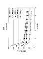
- FIG. 6 is a diagram showing cycle characteristics of Examples 1-1, 1-4, 1-6, and 1-7, and Comparative Example 1-1.
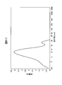
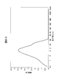
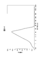
- FIG. 6 is a graph showing the pore size distribution of secondary particles in Example 1-5. It is a figure which shows the pore size distribution of the secondary particle of Comparative Example 1-2.
- FIG. 4 is a graph showing the pore size distribution of secondary particles of Example 1-5 and Example 1-8.
- the electrode active material secondary particles of the present invention are electrode active material secondary particles comprising a plurality of primary particles and a conductive carbon material, and the plurality of primary particles are a plurality of silicon-based particles or a positive electrode active material.
- the electrode active material secondary particles satisfy at least one of the following (i) to (iv): (I) a conductive carbon material is interposed between a plurality of primary particles; (Ii) the peripheral edge portion is denser than the central portion; and (iii) the BET specific surface area is 0.2 m 2 / g to 100 m 2 / g, (Iv) It has a peak top of more than 0.2 ⁇ m and 10 ⁇ m or less in a pore distribution curve by a mercury intrusion method.
- a conductive carbon material is interposed between a plurality of primary particles of the electrode active material secondary particles.
- the electrical conductivity of the electrode active material secondary particles can be increased. Therefore, according to the electrode active material secondary particles of this aspect, the cycle characteristics and the like of the secondary battery having the electrode active material secondary particles can be improved.
- the portion where the conductive carbon material is interposed between the plurality of primary particles may be the peripheral portion of the electrode active material secondary particle of the present invention, the central portion, or the peripheral portion and the central portion, that is, The entire electrode active material secondary particles may be used.
- the peripheral part of an electrode active material secondary particle is dense compared with a center part.
- the electrical conductivity and structural strength of the electrode active material secondary particles can be enhanced by the presence of the plurality of primary particles and the conductive carbon material in the periphery.
- a plurality of primary particles and a conductive carbon material are sparsely present in the central portion, so that a vacancy exists in the central portion, and silicon-based particles or positive electrode active material particles expand during insertion and release of lithium ions and the like. Even when contracted, the secondary particles can be prevented from collapsing. Therefore, according to the electrode active material secondary particles of this aspect, the cycle characteristics and the like of the secondary battery having the electrode active material secondary particles can be improved.
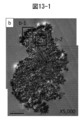
- FIGS. 8-1 to 8-3 Examples of secondary particles of the electrode active material of the present invention in which the peripheral part is denser than the central part are shown in FIGS. 8-1 to 8-3 and the like.
- the roughness of the “peripheral edge” and “center” of the secondary electrode active material particles is obtained by thinning the electrode active material secondary particles by focusing ion beam (FIB) processing (film thickness: about 100 nm).
- the sample can be evaluated based on a cross-sectional photograph of the electrode active material secondary particles obtained by observation with a field emission scanning transmission electron microscope (FE-STEM).
- the “peripheral part” of the electrode active material secondary particle is, for example, a cross-section of the electrode active material secondary particle from the outside of the cross section of the electrode active material secondary particle toward the center in the cross-sectional photograph of the electrode active material secondary particle. It means a portion of up to 10%, 20% or 30% of the shortest diameter.
- the “center portion” of the electrode active material secondary particles means a portion other than the “peripheral portion” in this cross-sectional photograph.
- At least two vacancies continuously exist in the center of the electrode active material secondary particle of the present invention whereby the longest diameter of the vacancies continuously present is preferably from 0.02 ⁇ m to The thickness is 0.4 ⁇ m, more preferably 0.03 ⁇ m to 0.3 ⁇ m, still more preferably 0.04 ⁇ m to 0.2 ⁇ m.
- the electrode active material secondary particles have a BET specific surface area of 0.2 m 2 / g to 100 m 2 / g, preferably 1 m 2 / g to 90 m. 2 / g, more preferably 5 m 2 / g to 70 m 2 / g (in the present invention, the BET specific surface area may be simply abbreviated as “specific surface area”).
- the BET specific surface area when the BET specific surface area is too small, that is, when the primary particle diameter is too large, structural variations in the secondary particles are large, which may adversely affect battery characteristics. Moreover, when the BET specific surface area is too large, that is, when the primary particle diameter is too small, the effect obtained by making the electrode active material into secondary particles may not be obtained. In addition, since the BET specific surface area is in the above range, a large amount of binder and / or conductive aid is not required, and therefore the binder and / or conductive aid adversely affects battery characteristics such as cycle characteristics. Can prevent that.
- the BET specific surface area (m 2 / g) of the electrode active material secondary particles of the present invention is determined using a specific surface area / pore distribution measuring device, for example, a specific surface area / pore distribution measuring device “ASAP2020” manufactured by Micromeritics, It can be determined using nitrogen as an adsorbate.
- a specific surface area / pore distribution measuring device for example, a specific surface area / pore distribution measuring device “ASAP2020” manufactured by Micromeritics, It can be determined using nitrogen as an adsorbate.
- the pore distribution curve of the electrode active material secondary particles by mercury intrusion method is more than 0.2 ⁇ m and not more than 10 ⁇ m, not less than 1.0 ⁇ m and not more than 10 ⁇ m, Alternatively, it has a peak top of 2 ⁇ m or more and 8 ⁇ m or less.
- the “pore distribution curve” is the sum of pore volumes per unit weight (usually 1 g) of pores having a radius equal to or larger than the logarithm of the radius of the pores on the horizontal axis.
- the value obtained by differentiating the logarithm of the pore radius (Log differential pore volume (mL / g)) is plotted on the vertical axis, and is usually expressed as a graph connecting the plotted points.
- Peak top refers to the point at which the coordinate value of the vertical axis takes the largest value in each peak of the pore distribution curve.
- the mercury intrusion method for example, injects mercury into the pores of a sample such as a porous particle while applying pressure. From the relationship between the pressure and the amount of mercury injected, the specific surface area, pore size distribution, etc. It is a technique for obtaining information.
- the container containing the sample is evacuated and filled with mercury.
- Mercury has a high surface tension and does not enter the pores on the sample surface as it is, but when pressure is applied to the mercury and the pressure is gradually increased, the pores gradually increase from the pores with the largest diameter to the pores with the smallest diameter.
- Mercury enters the pores.
- a mercury intrusion curve that represents the relationship between the pressure applied to mercury and the amount of mercury intrusion, if changes in the mercury liquid level (that is, changes in the amount of mercury intrusion into the pores) are detected while increasing the pressure continuously. Is obtained.
- the size of the pore radius of the sample and its volume are calculated based on the obtained mercury intrusion curve.
- a pore distribution curve representing the relationship can be obtained. For example, when the pressure P is changed from 0.1 MPa to 100 MPa, the pores in the range from about 7500 nm to about 7.5 nm can be measured.
- the lower limit is about 2 nm or more, and the upper limit is about 200 ⁇ m or less.
- the measurement by the mercury intrusion method can be performed using a mercury porosimeter, for example, Autopore IV (Shimadzu Corporation).
- the silicon-based particles used as the plurality of primary particles in the electrode active material secondary particles of the present invention mean silicon compounds in which the x value of SiO x is 0 ⁇ x ⁇ 2, particularly silicon particles in which x is about 0. .
- the method for producing silicon-based particles is not particularly limited.
- a method as disclosed in JP-T-2010-514585 can be used.
- silicon particles include silicon particles obtained by a laser pyrolysis method, particularly a laser pyrolysis method using a CO 2 laser.
- Another possible method is to prepare silicon particles by preparing SiO 2 by a sol-gel method and then performing a reduction treatment.
- the silicon-based particles are doped with a doping element at a concentration of 1.0 ⁇ 10 19 atoms / cm 3 or more, 1.0 ⁇ 10 20 atoms / cm 3 or more, or 1.0 ⁇ 10 21 atoms / cm 3 or more. It may be.
- the doping element may be selected from the group consisting of Group 13 and Group 15 elements of the periodic table. For example, boron (B), aluminum (Al), gallium (Ga), indium (In), titanium (Ti) , Phosphorus (P), arsenic (As), antimony (Sb), nitrogen (N), and combinations thereof.
- Positive electrode active material particles As the positive electrode active material particles used as the primary particles, primary particles containing a compound selected from the group consisting of olivine compounds, polyanion compounds, silicate compounds, Li-excess solid solution compounds, and combinations thereof are used. Can be used.
- the conductive carbon material contained in the electrode active material secondary particles of the present invention is not particularly limited as long as it is a conductive carbon material.
- the conductive carbon material include carbon black, graphite, and acetylene black.
- a precursor for carbonization to obtain a carbon material particularly polymer material, for example, phenol resin, polyethylene, polypropylene, polyvinyl alcohol, polystyrene, furan resin, cellulose resin, epoxy resin, polyvinyl chloride, polymethyl methacrylate resin, Polyvinylidene fluoride, pitch, coke, biowaste, furfuryl alcohol, and any combination thereof.
- these polymer materials may have a dopant element selected from the group consisting of boron, aluminum, gallium, indium, titanium, phosphorus, arsenic, antimony, and combinations thereof.
- these polymeric materials may be polymers selected by the group consisting of polymers cured with hexamethylenetetramine, polyvinyl pyrrolidone, polyamides, polyacrylonitrile, and combinations thereof.
- the electrode active material secondary particles of the present invention may have at least a part of the surface thereof coated with a conductive carbon material, and such a conductive carbon material is contained in the electrode active material secondary particles. It may be the same as or different from the conductive carbon material used.
- a plurality of primary particles contained in the electrode active material secondary particles of the present invention can have any size, for example, the average primary particle diameter is 1 nm or more, or 3 nm or more, 1 ⁇ m or less, 500 nm or less, It can have an average particle size of 100 nm or less, 50 nm or less, 30 nm or less, 20 nm or less, or 10 nm or less.
- the average primary particle size is preferably 5 nm to 300 nm, more preferably 10 nm to 200 nm.
- the average particle diameter of the plurality of primary particles contained in the electrode active material secondary particles of the present invention is based on an image taken by observation with a scanning electron microscope (SEM), a transmission electron microscope (TEM), or the like.
- SEM scanning electron microscope
- TEM transmission electron microscope
- the particle diameter can be directly measured, and a particle group consisting of 100 or more aggregates can be analyzed to obtain the number average particle diameter.
- the average primary particle diameter can be calculated based on a set of 500 or more by performing TEM observation and performing image analysis at a magnification of 100,000 times.
- the average particle diameter of the electrode active material secondary particles of the present invention can have an arbitrary size.
- the average particle size is preferably 40 nm or more and 100 ⁇ m or less, more preferably 1 ⁇ m or more and 50 ⁇ m or less, and further preferably 3 ⁇ m or more and 10 ⁇ m or less.
- the average particle diameter of the electrode active material secondary particles of the present invention can be determined from the particle size distribution by the laser diffraction scattering method.
- the electrode active material secondary particles of the present invention can be obtained by any method. For example, (a) a plurality of primary particles, a conductive carbon material and / or precursor thereof, and a solvent are mixed to obtain a mixed solution. (B) spray-drying the mixture to form dry secondary particles, and optionally (c) produced by a process comprising calcining the resulting dry secondary particles at 500 ° C. to 1400 ° C. can do.
- the solvent used in obtaining the electrode active material secondary particles of the present invention is not particularly limited as long as it can be used as a solvent, and examples thereof include acidic aqueous solutions, neutral aqueous solutions, and alkaline aqueous solutions. .
- the solvent when silicon particles are used as the primary particles, the solvent is preferably an alkaline aqueous solution.
- the pH of the alkaline aqueous solution is not particularly limited as long as it shows alkalinity, and is preferably pH 7 to pH 14, more preferably pH 7 to pH 12, and further preferably pH 8 to pH 10.
- the dispersion medium is not particularly limited, and is preferably isopropanol (IPA).
- the order of addition is not particularly limited as long as a plurality of primary particles, a conductive carbon material and / or a precursor thereof, and a solvent can be mixed.
- the conductive carbon material and / or its precursor is added to the solvent, and the mixture is stirred for a predetermined time with heat, and finally a plurality of primary particles are added and mixed.
- the predetermined time and heat treatment conditions are not particularly limited as long as the conductive carbon material and / or its precursor is sufficiently dispersed and / or dissolved in the solvent, and preferably 2 hours to 24 hours and 80 ° C. to 600 ° C., respectively. ° C.
- the spray drying step is a step of spray drying a mixed liquid containing a plurality of primary particles, a conductive carbon material and / or a precursor thereof, and a solvent by applying heat. By passing through the step of spray-drying, the solvent, optional dispersion medium, etc. contained in the mixed solution are removed, and powdered secondary particles are obtained.
- a general spray dryer apparatus can be used. Specifically, the mixed solution is put into a nozzle attached to the chamber.
- the temperature of the nozzle spray port can be 40 ° C. to 220 ° C.
- the nozzle diameter can be 400 to 800 ⁇ m.
- hot air of 20 ° C. to 200 ° C. is applied in the chamber, whereby the solvent and the like are dried.
- the product is passed through the outlet of a chamber set at 0 ° C. to 100 ° C., placed in a cyclone, and sent to a collection vessel with hot air of 70 ° C. to 180 ° C. Thereby, the powdered electrode active material secondary particles are collected in the cyclone product container, and the remainder is removed.
- the precursor of the conductive carbon material is carbonized by the firing step (c) to obtain the conductive carbon material.
- the firing temperature is, for example, 500 ° C. to 1400 ° C., preferably 600 ° C. to 1350 ° C., more preferably 650 ° C. to 1300 ° C.
- the firing temperature means the maximum temperature under firing conditions. Therefore, as the pre-heat treatment, preliminary firing at a relatively low temperature, for example, 200 to 1000 ° C., may be performed to perform stepwise firing.
- the atmosphere of the firing step is not particularly limited, and an atmosphere of a gas selected from the group consisting of nitrogen, argon, air, hydrogen, helium, and combinations thereof can be used.
- the negative electrode layer of the present invention contains electrode active material secondary particles containing silicon-based particles, a conductive additive, and a binder. Unexpectedly, the negative electrode layer of the present invention can improve cycle characteristics and the like when used in a non-aqueous electrolyte secondary battery.
- the conductive additive contained in the negative electrode layer of the present invention is not particularly limited as long as the conductivity of the negative electrode layer can be improved.
- the conductive aid includes a carbon material selected from the group consisting of carbon black, graphite, acetylene black, carbon fiber, or combinations thereof.
- the conductive assistant it is considered preferable to use carbon fibers, particularly ultrafine fibrous carbon having an average fiber diameter of 10 to 900 nm that does not have a branched structure in terms of improving cycle characteristics. With respect to such ultrafine fibrous carbon, for example, the description in JP-A-2010-245423 can be referred to.
- the binder contained in the negative electrode layer of the present invention is not particularly limited as long as the negative electrode active material can be bound to the current collector. Therefore, for example, polyvinylidene fluoride (PVdF), PTFE particles, water-based rubber particles, epoxy, polyimide, polyamideimide, cellulose, CMC (carboxymethylcellulose), styrene-butadiene-copolymer, polyacrylate, polyurethane, etc. are used as binders Can do.
- PVdF polyvinylidene fluoride
- PTFE particles water-based rubber particles
- epoxy epoxy
- polyimide polyamideimide
- cellulose CMC (carboxymethylcellulose)
- styrene-butadiene-copolymer polyacrylate
- polyurethane etc.
- the negative electrode of the present invention has a current collector and the negative electrode layer of the present invention laminated on the current collector.
- the negative electrode current collector of the present invention can be formed of any conductive material.
- the current collector can be formed from a metal material such as aluminum, nickel, iron, stainless steel, titanium, copper, in particular aluminum, stainless steel, copper.
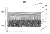
- the negative electrode of the present invention can have a structure as shown in FIG. That is, in the negative electrode 100 of the present invention, on the surface of the current collector 10, the electrode active material secondary particles 11 of the present invention containing silicon-based particles, the conductive auxiliary agent (not shown), and the binder (not shown). A negative electrode layer containing may be formed.
- the electrode active material secondary particles 11 contain a plurality of primary particles (11-1) which are negative electrode active materials, that is, silicon-based particles.
- the negative electrode of the present invention can be produced by any method.
- a negative electrode layer containing a negative electrode active material, an optional binder, an optional conductive additive and the like is dispersed in a dispersion medium, and the dispersed negative electrode layer is applied to a current collector and dried. It can be obtained by optionally firing.
- the dispersion medium in this case is not limited as long as the object and effect of the present invention are not impaired, and therefore, for example, an organic solvent can be used.
- the dispersion medium may be a non-aqueous solvent such as alcohol, alkane, alkene, alkyne, ketone, ether, ester, aromatic compound, or nitrogen-containing ring compound, particularly isopropyl alcohol (IPA), or It may be N-methyl-2-pyrrolidone (NMP).
- IPA isopropyl alcohol
- NMP N-methyl-2-pyrrolidone
- the drying temperature can be selected so as not to deteriorate the electrode active material secondary particles of the present invention, for example, 50 ° C. or higher, 70 ° C. or higher, or 90 ° C. or higher, and 100 ° C. or lower, 150 ° C.
- it can be selected to be 200 ° C. or lower or 250 ° C. or lower.
- the positive electrode layer of the present invention contains the electrode active material secondary particles of the present invention containing positive electrode active material particles, a conductive additive, and a binder.
- the positive electrode layer of the present invention can increase the capacity of the non-aqueous electrolyte secondary battery when used in the non-aqueous electrolyte secondary battery, improve the cycle characteristics, and / or the initial stage. Charge / discharge efficiency can be increased.
- the description relating to the negative electrode layer of the present invention can be referred to.
- the positive electrode of the present invention has a current collector and the positive electrode layer of the present invention laminated on the current collector.
- the description relating to the negative electrode layer of the present invention can be referred to.
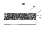
- the positive electrode of the present invention can have a configuration as shown in FIG. That is, in the positive electrode 200 of the present invention, the electrode active material secondary particles 13 of the present invention containing the positive electrode active material particles, the conductive auxiliary agent (not shown), and the binder (not shown) on the surface of the current collector 12. ) -Containing positive electrode layer may be formed.
- the electrode active material secondary particles 13 contain a plurality of primary particles (13-1) which are positive electrode active material particles.
- the positive electrode of the present invention can be produced by any method, and specifically, the description relating to the negative electrode layer of the present invention can be referred to.
- the nonaqueous electrolyte secondary battery of the present invention is, for example, a lithium ion secondary battery, a lithium battery, a lithium ion polymer battery, or the like, preferably a lithium ion secondary battery.
- the nonaqueous electrolyte secondary battery of the present invention includes the negative electrode layer of the present invention and / or the positive electrode layer of the present invention.
- the nonaqueous electrolyte secondary battery of the present invention can have a configuration in which a positive electrode current collector, a positive electrode layer, a separator and / or a solid electrolyte layer, a negative electrode layer, and a negative electrode current collector are laminated. .
- the liquid electrolyte is impregnated in the positive electrode layer, the negative electrode layer, and the like of the laminate, and / or the solid electrolyte is the positive electrode layer, the negative electrode layer, and the like of the laminate. Dispersed in.
- the electrolyte for the non-aqueous electrolyte secondary battery of the present invention is not limited as long as the object and effect of the present invention are not impaired. Therefore, for example, a nonaqueous electrolytic solution in which a lithium salt is dissolved in a highly polar nonaqueous solvent can be used. However, when such a liquid electrolyte is used, it is generally preferable to use a separator made of a porous layer in order to prevent direct contact between the positive electrode active material layer and the negative electrode active material layer.
- lithium salt examples include LiClO 4 , LiBF 4 , LiAsF 6 , LiPF 6 , LiSCN, LiBr, LiI, Li 2 SO 4 , Li 2 B 10 Cl 10 , LiCF 3 SO 3 , LiN (CF 3 SO 2) 2, LiN (C 2 F 5 SO 2) 2, LiN (CF 3 SO 2) (C 4 F 9 SO 2), LiC (CF 3 SO 2) 3, LiC (C 2 F 5 SO 2) 3 , lithium stearyl sulfonate, lithium octyl sulfonate, lithium dodecylbenzene sulfonate, and the like, and these ionic compounds can be used alone or in admixture of two or more.
- Non-aqueous solvents used for the non-aqueous electrolyte include propylene carbonate (PC), ethylene carbonate (EC), diethyl carbonate (DEC), dimethyl carbonate (DMC), ethyl methyl carbonate (EMC), butylene carbonate, chloroethylene carbonate, etc.
- PC propylene carbonate
- EC ethylene carbonate
- DEC diethyl carbonate
- DMC dimethyl carbonate
- EMC ethyl methyl carbonate
- butylene carbonate chloroethylene carbonate, etc.
- Cyclic carbonates such as: cyclic esters such as ⁇ -butyrolactone and ⁇ -valerolactone; chain carbonates such as dimethyl carbonate, diethyl carbonate and ethyl methyl carbonate; chain esters such as methyl formate, methyl acetate and methyl butyrate Tetrahydrofuran or derivatives thereof; ethers such as 1,3-dioxane, 1,4-dioxane, 1,2-dimethoxyethane, 1,4-dibutoxyethane, methyldiglyme; acetonitrile, benzonitrile, etc.
- propylene carbonate, ethylene carbonate, ⁇ -butyrolactone, dimethyl carbonate, diethyl carbonate, and ethyl methyl carbonate are preferably used as the non-aqueous solvent used in the non-aqueous electrolyte.
- nonaqueous solvents may be used alone or in combination of two or more.
- lithium salts for the liquid electrolyte may use LiPF 6, LiClO 4, LiN ( CF 3 SO 2) 2, LiBF 4 or the like. These lithium salts may be used alone or in combination of two or more.
- the concentration of the electrolyte salt (lithium salt) in the non-aqueous electrolyte is preferably 0.1 mol / L to 5 mol / L, more preferably 0.5 mol in order to reliably obtain a non-aqueous electrolyte battery having high battery characteristics. / L to 2.5 mol / L.
- additives that improve reduction resistance and oxidation resistance to the non-aqueous electrolyte for the purpose of improving the cycle characteristics and storage characteristics of the battery.
- reduction polymerization compounds such as vinylene carbonate and vinyl acetate
- oxidizing compounds such as biphenyl, terphenyl, pyrrole, aniline, and thiophene.
- the amount of the additive to be added is preferably 0.1 to 3% by weight.
- a flame retardant may be added from the viewpoint of improving battery safety.
- the flame retardant include phosphazene compounds and phosphate ester compounds.
- the preferred addition amount is 1 to 20% by weight.
- ionic liquid room temperature molten salt (ionic liquid) made of a lithium salt
- it can be mixed with the non-aqueous electrolyte.
- electrolytes function as an electrolyte layer by being impregnated and held in a separator having a porous structure.
- the thickness of the electrolyte layer (that is, the thickness of the separator) is preferably as thin as possible to reduce the internal resistance, and is usually 1 to 100 ⁇ m, preferably 5 to 50 ⁇ m.
- the porosity of the separator is preferably 90% by volume or less from the viewpoint of strength. Moreover, the porosity of the separator is preferably 20% by volume or more from the viewpoint of charge / discharge characteristics.
- the separator it is preferable to use a microporous film or a nonwoven fabric exhibiting excellent high rate discharge performance alone or in combination.
- microporous film used as the separator examples include a single layer film or a laminated film of a polyolefin resin typified by polyethylene, polypropylene and the like.
- microporous membrane examples include polytetrafluoroethylene, polyvinylidene fluoride, vinylidene fluoride-hexafluoropropylene copolymer, vinylidene fluoride-perfluorovinyl ether copolymer, vinylidene fluoride-tetrafluoroethylene copolymer, Vinylidene fluoride-trifluoroethylene copolymer, vinylidene fluoride-fluoroethylene copolymer, vinylidene fluoride-hexafluoroacetone copolymer, vinylidene fluoride-ethylene copolymer, vinylidene fluoride-propylene copolymer, Fluorine microporous membranes such as vinylidene fluoride-trifluoropropylene copo
- nonwoven fabric used as the separator a polyester-based resin typified by polyethylene terephthalate, polybutylene terephthalate, and the like, a dry nonwoven fabric using a fiber material such as cellulose, aramid, and glass fiber, and a wet nonwoven fabric by a papermaking method can be used. Nanofibers are preferably used as the fiber material from the viewpoint of microporous formation.
- separators with good oxidation resistance are particularly preferred, and fluororesins, aramids, or ceramic-coated ones are preferably used on substrates such as porous membranes and nonwoven fabrics. Is done.
- a gel polymer electrolyte obtained by gelling a non-aqueous electrolyte can also be applied from the viewpoint of preventing battery leakage.
- the gel polymer electrolyte can be obtained by combining a non-aqueous electrolyte with a polymer that swells and gels and a non-aqueous electrolyte.
- polyswells and gels examples include polyethylene oxide (PEO), polypropylene oxide (PPO), polyvinylidene fluoride (PVDF), a copolymer of polyvinylidene fluoride and hexafluoropropylene (PVDF-HFP), polyethylene glycol ( PEG), polyacrylonitrile (PAN), polymethyl methacrylate (PMMA), polysiloxane, copolymers thereof, and cross-linked products thereof.
- PEO polyethylene oxide
- PPO polypropylene oxide
- PVDF polyvinylidene fluoride
- PVDF-HFP a copolymer of polyvinylidene fluoride and hexafluoropropylene
- PEG polyethylene glycol
- PAN polyacrylonitrile
- PMMA polymethyl methacrylate
- polysiloxane copolymers thereof, and cross-linked products thereof.
- a solid electrolyte can be used as the electrolyte layer, and in this case, a separate spacer can be omitted.
- the nonaqueous electrolyte secondary battery of the present invention can have, for example, the configuration shown in FIGS.
- the positive electrode 400 composed of the positive electrode current collector 17 and the positive electrode layer 16, the electrolyte layer 15, and the negative electrode 100 composed of the negative electrode current collector 10 and the negative electrode layer 14 of the present invention.
- the positive electrode layer 16 of the positive electrode 400 faces the negative electrode layer 14 of the negative electrode 100, and the electrolyte layer 15 is inserted between the positive electrode layer 16 and the negative electrode layer 14.
- FIG. 3 also shows that the electrode active material secondary particles 11 of the present invention contain a plurality of primary particles 11-1.
- the positive electrode 200 composed of the positive electrode current collector 12 and the positive electrode layer 18 of the present invention, the electrolyte layer 15, and the negative electrode 600 composed of the negative electrode current collector 20 and the negative electrode layer 19.
- the positive electrode layer 18 of the positive electrode 200 faces the negative electrode layer 19 of the negative electrode 600, and the electrolyte layer 15 is inserted between the positive electrode layer 18 and the negative electrode layer 19.
- FIG. 4 also shows that the electrode active material secondary particles 13 of the present invention contain a plurality of primary particles 13-1.
- the positive electrode 200 of the present invention comprising the positive electrode current collector 12 and the positive electrode layer 18 of the present invention, the electrolyte layer 15, the negative electrode current collector 10 and the negative electrode of the present invention.
- a negative electrode 100 made of the layer 14 is laminated.
- the negative electrode layer 14 of the negative electrode 100 faces the positive electrode layer 18 of the positive electrode 200, and the electrolyte layer 15 is inserted between the positive electrode layer 18 and the negative electrode layer 14.
- the electrode active material secondary particles 11 of the present invention contain a plurality of primary particles 11-1
- the electrode active material secondary particles 13 of the present invention contain a plurality of primary particles 13-1. It has also been shown to do.
- Example 1-1 Preparation of silicon particles (primary particles) Silicon particles were produced by a laser pyrolysis (LP) method using monosilane gas as a raw material and using a carbon dioxide (CO 2 ) laser. At this time, PH 3 gas was introduced together with SiH 4 gas to obtain phosphorus-doped silicon particles.
- LP laser pyrolysis
- CO 2 carbon dioxide
- the obtained phosphorus-doped silicon particles had a do pink concentration of 1 ⁇ 10 21 atoms / cm 3 and an average primary particle diameter of 20.0 nm.
- phosphorus-doped silicon particles were dispersed in isopropanol (IPA) to obtain a 0.5 mass% silicon particle dispersion.
- IPA isopropanol
- the mixed solution mixed above was immediately spray dried using a spray dryer apparatus (ADL311S-A manufactured by Yamato Scientific Co., Ltd.). First, the mixed solution was put into a nozzle attached to the chamber and sprayed. The temperature of the nozzle inlet was 170 ° C., and the nozzle diameter was 406 ⁇ m. Isopropanol (IPA) and water contained in the mixed solution were removed by hot air drying.
- IPA Isopropanol
- Example 1-2 4 g of powdery secondary particles were obtained in the same manner as in Example 1-1 except that 0.4% by mass of polyvinyl alcohol (PVA) was used.
- PVA polyvinyl alcohol
- Example 1-3 4 g of powdery secondary particles were obtained in the same manner as in Example 1-1 except that 0.5% by mass of polyvinyl alcohol (PVA) was used.
- PVA polyvinyl alcohol
- Example 1-4 3 g of powdery secondary particles were obtained in the same manner as in Example 1-1 except that 0.7% by mass of polyvinyl alcohol (PVA) was used.
- PVA polyvinyl alcohol
- Example 1-5 In the same manner as in Example 1-1, except that 1.5% by mass of polyvinyl alcohol (PVA) was used, and the temperature of the nozzle inlet attached to the chamber of the spray dryer apparatus was set to 100 ° C., Powdered secondary particles were obtained.
- PVA polyvinyl alcohol
- Example 1-6 The powdered composite secondary particles obtained in Example 1-1 were fired in a nitrogen atmosphere in an electric furnace at 700 ° C., and the polyvinyl alcohol (PVA) contained in the composite secondary particles was carbonized to form a conductive carbon system. Made into material.
- PVA polyvinyl alcohol
- Example 1--7 The powdered secondary particles obtained in Example 1-4 were baked in a nitrogen atmosphere in an electric furnace at 700 ° C. to carbonize polyvinyl alcohol (PVA) contained in the secondary particles to obtain a conductive carbon-based material. did.
- PVA polyvinyl alcohol
- Example 1-8 The powdered secondary particles obtained in Example 1-5 were baked in a nitrogen atmosphere in an electric furnace at 700 ° C. to carbonize polyvinyl alcohol (PVA) contained in the secondary particles to obtain a conductive carbon-based material. did.
- PVA polyvinyl alcohol
- Example 1-2 Powdered silicon secondary particles were obtained in the same manner as in Example 1-1 except that the polyvinyl alcohol (PVA) aqueous solution was not used.
- PVA polyvinyl alcohol
- Example 2-1 Preparation of silicon particles (primary particles) Silicon particles were produced by a laser pyrolysis (LP) method using a carbon dioxide (CO 2 ) laser using monosilane (SiH 4 ) gas as a raw material. At this time, PH 3 gas was introduced together with SiH 4 gas to obtain phosphorus-doped silicon particles.
- LP laser pyrolysis
- CO 2 carbon dioxide
- SiH 4 monosilane
- the obtained phosphorus-doped silicon particles had a dopink concentration of 1 ⁇ 10 21 atoms / cm 3 and an average particle size of 35.0 nm.
- phosphorus-doped silicon particles were dispersed in isopropanol (IPA) to obtain a 5 mass% silicon particle dispersion.
- IPA isopropanol
- the mixed solution mixed above was immediately spray dried using a spray dryer apparatus (ADL311S-A manufactured by Yamato Scientific Co., Ltd.). First, the mixed solution was put into a nozzle attached to the chamber and sprayed. The nozzle inlet temperature was 135 ° C., and the nozzle diameter was 406 ⁇ m. Isopropanol (IPA) and acetone contained in the mixed solution were removed by hot air drying.
- IPA isopropanol
- Example 2-2 Powdered 3.6 g of secondary particles were obtained in the same manner as in Example 2-1, except that an acetone solution containing 2.5% by mass of a phenol resin was used.
- Example 2-3 A powdery 0.06 g of secondary particles was obtained in the same manner as in Example 2-1, except that an acetone solution containing 10.0% by mass of a phenol resin was used. Although the yield was low here, it is thought that the amount collected can be increased by optimizing the temperature.
- Example 2-4 The powdered secondary particles obtained in Example 2-2 were carbonized to carbonize the phenol resin to obtain a conductive carbon material.
- the carbonization treatment was first carried out in a baking furnace at 700 ° C. and 0.5 hour, followed by 1150 ° C. and 4 hours, and finally cooled to room temperature.
- particle size distribution measurement About the particle
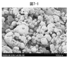
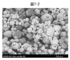
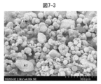
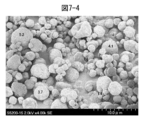
- FIGS. 7-1 to 7-4 SEM photographs (shooting magnification ⁇ 4000) for Examples 1-1 to 1-4 are shown in FIGS. 7-1 to 7-4. Further, SEM photographs (shooting magnification ⁇ 3000) for Example 2-2 and Example 2-4 are shown in FIGS.
- the specific surface area of the silicon-based particles having an average particle diameter of 20 nm in Comparative Example 1-1 is 130 m 2 / g, whereas the secondary particles obtained in Examples 1-1 to 1-5 are compared therewith. Since it has a small specific surface area, it can be understood that the secondary particles have a structure in which a plurality of primary particles (silicon particles) are covered with polyvinyl alcohol to form secondary particles. Since the secondary particles of Comparative Example 1-2 have a specific surface area of 82 m 2 / g, it can be understood that there is not much difference from the specific surface area of the silicon particles themselves of Comparative Example 1-1. On the other hand, it can be understood that the specific surface area (4.0 to 37.8 m 2 / g) of the secondary particles obtained in Example 1-1 to Example 1-5 was significantly reduced.
- Example 2-1 to 2-4 Comparative Example 1-1, and Comparative Example 1-2
- the average particle sizes of the secondary particles obtained in Example 2-1 to Example 2-3 were 6.5 ⁇ m, 9.8 ⁇ m, and 3.3 ⁇ m, respectively.
- the secondary particles before carbonization (before firing) (Example 2-2 (FIG. 10)) has a specific surface area of 22 m 2 / g, whereas the secondary surface after carbonization (after firing).
- the specific surface area of the particles (Example 2-4 (FIG. 11)) was 41 m 2 / g. Therefore, it can be understood that the specific surface area is slightly increased by carbonization (firing).
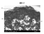
- FIGS. 8-2 and 8-3 are partially enlarged photographs of the vicinity of the portion e in FIG. 8-1 and the portion near the portion f in FIG. 8-1 (shooting magnification ⁇ 200,000).
- the peripheral edge of the secondary particle is coated with polyvinyl alcohol (C: gray part of the photograph), and a plurality of primary particles are provided at the peripheral edge of the secondary particle. It can be understood that (silicon particles) (B: black part of the photograph) are bonded to each other via polyvinyl alcohol (C: gray part of the photograph).
- a plurality of primary particles (silicon particles) (B: black portion) are mutually connected via polyvinyl alcohol (C: gray portion of the photograph) at the center of the secondary particles. It can be understood that they are combined. Further, in FIG. 8-3, several holes (A: white portion of the photograph) are observed.
- the carbon (conductive carbon material) having a thickness of about 9% (about 0.9 ⁇ m if the secondary particles have a diameter of 10 ⁇ m) is a particle present on the entire periphery of the secondary particles.
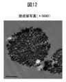
- Example 2-8 when Example 2-8 is confirmed, as shown in the FE-STEM photograph of FIG. 12, since carbon is also present in the secondary particles, the carbon (conductive carbon material) present in the entire periphery of the particles. ), And the thickness of the carbon (conductive carbon material) at the periphery is 30 nm (average diameter in terms of sphere) with respect to the secondary particle diameter of 600 nm, based on the observation result of the FE-STEM photograph in FIG. About 5%).
- silicon particles and carbon are densely present at the periphery of the secondary particles obtained in Example 2-4. It can be understood that the center part is sparse and there are holes (white part of the photograph).
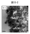
- FIG. 13-2 and FIG. 13-3 are partially enlarged photographs near the b-1 part and the b-2 part in FIG. 13-1, respectively (photographing magnification ⁇ 30,000).
- the peripheral portion is coated with carbon (the gray portion of the photograph), and a plurality of primary particles (silicon particles) (the black portion of the photograph) are formed at the peripheral portion of the secondary particle. It can be seen that the (parts) are bonded to each other via carbon (the gray part of the photograph).
- FIG. 13-3 a plurality of primary particles (silicon particles) (black part of the photograph) are bonded to each other via carbon (gray part of the photograph) at the center of the secondary particle. Understandable. Further, in FIG. 13-3, several holes (white part of the photograph) are observed.
- the negative electrode layer was applied to a thickness of 20 ⁇ m on a current collector made of copper foil having a thickness of 20 ⁇ m using an applicator, dried in a hot air dryer at 80 ° C. for 3 hours, and further 120 ° C. And dried for 5 hours and pressed by a roll press to produce a negative electrode.
- the produced negative electrode was punched into a circle having a diameter of 14 mm to obtain a negative electrode (working electrode).
- Negative electrode half-cell by sandwiching a porous polyethylene film (E-20MMS manufactured by Tonen Chemical Co., Ltd.) as a separator between the obtained negative electrode (working electrode) and reference electrode A laminated body was obtained, this battery laminated body was housed in a battery case, and impregnated with an electrolytic solution to obtain a negative electrode half battery of Example 1-1. The work was performed in an argon dry box.
- the electrolytic solution was a solution obtained by dissolving 1 mol / L LiPF 6 in a 70:30 (volume ratio) mixed solvent of ethylene carbonate and ethyl methyl carbonate.
- the charge / discharge test was performed using a charge / discharge device (manufactured by Hokuto Denko Co., Ltd.) and the current density during charging and discharging was 0.1 mA / cm 2 or 1 mA / cm 2 .
- Charging is performed from the initial voltage to the lithium metal potential by the CC-CV method (constant current constant voltage method). Act). Charging was performed until the battery voltage reached 0.01V under a constant current / constant voltage condition of 1C rate, and discharging was performed until the battery voltage reached 1V under a constant current condition of 1C rate.
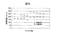
- This charge / discharge cycle was repeated 10 cycles, and the subsequent discharge capacity was measured. The result is shown in FIG.
- Example 1-4 Example 1-4, Example 1-6, and Example 1-7)
- a negative electrode half-cell was prepared in the same manner as in Example 1-1 except that the secondary particles obtained in Example 1-4, Example 1-6, and Example 1-7 were used. It produced and the charge / discharge test (10 cycles) was done.
- the material characteristic values of the obtained negative electrode are shown in Table 2 below. The results of the cycle characteristics are shown in FIG.
- Comparative Example 1-1 In the case of Example 1-1, except that the silicon particles obtained in Comparative Example 1-1: 50% by mass, acetylene black: 40% by mass, and binder (polyvinylidene fluoride (PVDF)): 10% by mass were used.
- a negative electrode half-cell was prepared and a charge / discharge test (10 cycles) was performed.
- the material characteristic values of the obtained negative electrode are shown in Table 2 below. The results of the cycle characteristics are shown in FIG.
- Examples 1-1, 1-4, 1-6, and 1-7 have a high initial discharge capacity, and there is no decrease in discharge capacity after 2 cycles, and good cycle characteristics up to 10 cycles. Can be obtained. On the other hand, it can be understood that Comparative Example 1-1 has a low initial discharge capacity, a decrease in discharge capacity after 2 cycles, and good cycle characteristics cannot be obtained up to 10 cycles.
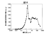
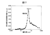
- FIGS. 14 to 17 are diagrams showing the measurement results of the pore size distribution of the secondary particles of the following Examples and Comparative Examples, respectively: FIG. 14: Example 1-5 FIG. 15: Comparative Example 1-2 FIG. 16: Example 1-5 and Example 1-8 FIG. 17: Example 2-4
- the horizontal axis (pore diameter) ( ⁇ m) represents the logarithm of the radius of the pore
- the vertical axis (mL / g) represents the unit mass of pores having a radius equal to or larger than the radius (usually normal)
- Example 1-5 and Comparative Example 1-2 [Evaluation of pore size distribution] (Example 1-5 and Comparative Example 1-2)
- the peak top of the secondary particles obtained in Example 1-5 that is, the secondary particles before carbonizing polyvinyl alcohol (PVA) was 1.5 ⁇ m.
- the peak top of the silicon-based secondary particles obtained in Comparative Example 1-2 that is, the silicon secondary particles not having polyvinyl alcohol (PVA) was 0.02 ⁇ m. Comparing the results of FIG. 14 and FIG. 15, it can be seen that small pores are likely to be formed without polyvinyl alcohol (PVA).
- Example 2-4 the peak top of the secondary particles obtained in Example 2-4, that is, the secondary particles after carbonizing the phenol resin was 2.5 ⁇ m.
- Carbon fiber was produced as follows. 90 parts by mass of high-density polyethylene (manufactured by Prime Polymer Co., Ltd., Hi-Zex 5000SR) as a thermoplastic resin and 10 parts by mass of mesophase pitch AR-MPH (manufactured by Mitsubishi Gas Chemical Co., Ltd.) as biaxially in the same direction
- the mixture was melt kneaded with an extruder (TEM-26SS manufactured by Toshiba Machine Co., Ltd., barrel temperature: 310 ° C., under nitrogen stream) to prepare a mixture.
- the dispersion diameter of the mixture obtained under these conditions in the thermoplastic carbon precursor in the thermoplastic resin was 0.05 to 2 ⁇ m.
- the mixture was kept at 300 ° C. for 10 minutes, but no aggregation of the thermoplastic carbon precursor was observed, and the dispersion diameter was 0.05 to 2 ⁇ m.
- long fibers having a fiber diameter of 100 ⁇ m were produced from the above mixture by a cylinder type single-hole spinning machine under a spinning temperature of 390 ° C.
- a 30 g / m 2 basis weight non-woven fabric made of this precursor fiber was prepared by a wet method, and this was sandwiched between stainless steel wire meshes and held in a hot air dryer at 215 ° C. for 3 hours to stabilize the nonwoven fabric.
- a resin composition was prepared.
- the wire mesh used here was a twill-woven stainless steel wire mesh with an opening of 1.46 mm and a diameter of 0.35 mm, and the wire mesh spacing was 10 mm.
- a nonwoven fabric made of a fibrous carbon precursor was produced by heating in a nitrogen gas atmosphere in a vacuum gas replacement furnace. As heating conditions, the temperature was raised to 500 ° C. at a rate of temperature rise of 5 ° C./min, and then held at the same temperature for 60 minutes.
- the pre-dispersed liquid in which the fibrous carbon precursor having a concentration of 0.1% by weight was dispersed was prepared by adding the nonwoven fabric composed of the fibrous carbon precursor to ion-exchanged water and pulverizing with a mixer for 2 minutes. This preliminary dispersion was treated 10 times with a wet jet mill (Sugino Machine Co., Ltd., Starburst Lab HJP-17007, used chamber: single nozzle chamber) with a nozzle diameter of 0.17 mm and a processing pressure of 100 MPa. By repeating, a liquid in which the fibrous carbon precursor was dispersed was produced.
- a wet jet mill Sudno Machine Co., Ltd., Starburst Lab HJP-17007, used chamber: single nozzle chamber
- the material in which this fibrous carbon precursor was dispersed was heated from room temperature to 3000 ° C. in an argon gas atmosphere in 3 hours to produce graphitized carbon fiber.
- the obtained carbon fiber had a fiber diameter of 300 to 600 nm, had almost no fiber aggregate in which the carbon fibers were fused, and was a carbon fiber having excellent dispersibility.
- Carbon fiber composite oxide particles precursor oxide particles containing manganese, cobalt, and nickel, which are precursors of the positive electrode active material, were prepared as follows.
- Nitric acid (HNO 3 ) aqueous solution and 35 wt% hydrogen peroxide water (H 2 O 2 ) were mixed at a volume ratio of 1: 3, and the carbon fiber prepared as described above was immersed in this aqueous solution for 48 hours. Then, ultrasonic irradiation was performed. Thereafter, washing and drying at 120 ° C. were performed.
- manganese sulfate pentahydrate (Wako Pure Chemical Industries, Ltd., first grade reagent) 13.64 g, cobalt nitrate hexahydrate (Wako Pure Chemical Industries, Ltd., special grade reagent) 2.06 g, and nickel nitrate hexahydrate 5.04 g of the product (manufactured by Wako Pure Chemical Industries, Ltd., special grade reagent) was dissolved in 100 ml of distilled water to prepare a metal salt aqueous solution. To the metal salt aqueous solution, acid-treated carbon fibers were added at a ratio of 1% with respect to the metal salt aqueous solution.
- the precursor oxide particle containing carbon fiber and manganese, cobalt, and nickel was obtained by oxidizing at 200 degreeC.
- this mixture was placed in a 50 ml alumina crucible and heat-treated in a firing furnace.
- heat treatment the temperature was raised to 650 ° C. at a rate of temperature rise of 5 ° C./min, heat treated for 6 hours, and then lowered to room temperature.
- the obtained powder was washed with distilled water, suction filtered, and dried at 100 ° C. for 5 hours to obtain the positive electrode active material secondary particles of Example 3.
- the surface and the cross-sectional structure were observed, it was confirmed to have a dense structure.
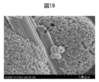
- the primary particle diameter is about 100 nm and the conductive carbon fiber (CNF) is interposed between the plurality of primary particles (see FIG. 19).
- composition of the positive electrode active material measured by the above method was Li [Li 0.2 Co 0.07 Ni 0.17 Mn 0.56 ] O 2 . Moreover, the SEM photograph obtained by the following method is shown in FIG.
- this mixture was put in a 100 ml alumina crucible and heat-treated in a firing furnace.
- the temperature was raised to 900 ° C. at a temperature raising rate of 10 ° C./min, heat treated for 8 hours, and then lowered to room temperature.
- the obtained powder was washed with distilled water, suction filtered, and dried at 100 ° C. for 5 hours to obtain a positive electrode active material of Comparative Example 3.
- the primary particle diameter was about 200 nm
- the inner side (center part) and the outer side (peripheral part) were uniform, and the structure was not dense.
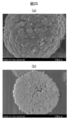
- the surface and cross section of the positive electrode active material secondary particles observed by the following method are shown in FIGS. 20 (a) and 20 (b), respectively.
- Example 3 75 parts by mass of the positive electrode active material obtained in Example 3 and Comparative Example 3, 20 parts by mass of acetylene black (Denka Black manufactured by Denki Kagaku Kogyo) as a conductive material, and polytetrafluoroethylene (manufactured by Daikin, F104) as a binder 5 parts by mass was mixed to prepare an electrode sheet so that the active material weight was a predetermined amount.
- acetylene black Denki Kagaku Kogyo
- polytetrafluoroethylene manufactured by Daikin, F104
- the produced electrode sheet was punched out into a circle with a diameter of 17 mm, then adhered to a 20 ⁇ m Al foil using a conductive paste (Nihon Graphite Industries, Ltd., Bunny Height T-602), and vacuum-dried at 170 ° C. for 10 hours to obtain a battery.
- a positive electrode for characteristic evaluation was obtained.
- Table 3 shows the physical properties of the produced positive electrode.
- the prepared positive electrode for the negative electrode, a metal lithium foil having a thickness of 200 ⁇ m (Honjo Chemical Co., Ltd.), and for the electrolyte solution, 1 mol / l LiPF 6 , ethylene carbonate and ethyl methyl carbonate (volume ratio 30:70).
- a separator of glass nonwoven fabric for the positive electrode, the prepared positive electrode, for the negative electrode, a metal lithium foil having a thickness of 200 ⁇ m (Honjo Chemical Co., Ltd.), and for the electrolyte solution, 1 mol / l LiPF 6 , ethylene carbonate and ethyl methyl carbonate (volume ratio 30:70).
- the charging upper limit voltage was set to 4.6 V and the discharging lower limit voltage was set to 2.0 V, and constant current / constant voltage charging was performed.
- Current density 48 mA / g (about 5 hours rate), followed by second cycle at 48 mA / g, third cycle at 120 mA / g, fourth cycle at 240 mA / g, fifth cycle at 480 mA / g
- a test was conducted at a current density of 48 mA / g from the 6th to the 10th cycle, with an upper limit voltage of charging being 4.8 V and a lower limit voltage of discharging being 2.0 V.
- the electrode active material secondary particles of the present invention are secondary particles comprising a plurality of primary particles and a conductive carbon material, and at least of the plurality of primary particles. Secondary particles, in which some primary particles are bonded to each other through the conductive carbon material.
- the secondary particles of the present invention include (a) a step of mixing the plurality of primary particles, the conductive carbon material, and a solvent, and (b) after the step (a). And a step of spray-drying.
- the secondary particles of the present invention are obtained by a method further comprising (c) a step of firing at 500 ° C.
- the secondary particles of the present invention are secondary particles comprising a plurality of primary particles and a conductive carbon material, wherein the plurality of primary particles and the conductive carbon material are densely arranged at the peripheral edge of the secondary particles. It is a secondary particle that exists and sparsely exists inside the secondary particle.
- At least two vacancies are continuously present on the inner side of the secondary particle, and the pore size is 0.02 ⁇ m to 0.4 ⁇ m.
- the secondary particles of the present invention are secondary particles comprising a plurality of primary particles and a conductive carbon material, and the BET specific surface area of the secondary particles is 0.2 m 2 / g to 100 m 2 / g. Secondary particles.
- the conductive carbon material is a polymer material containing a carbon atom.
- the average primary particle diameter of the plurality of primary particles is 5 nm or more and 300 nm or less.
- the average particle diameter of the secondary particles is 40 nm or more and 100 ⁇ m or less.
- the negative electrode active material of the present invention is a negative electrode active material containing the secondary particles of Embodiment 10.
- the negative electrode layer of this invention is a negative electrode layer containing the negative electrode active material of aspect 11, a conductive support agent, and a binder.
- the negative electrode of the present invention is a negative electrode comprising the negative electrode layer of Aspect 12 and a current collector.
- the plurality of primary particles are at least selected from the group consisting of an olivine compound, a polyanion compound, a silicate compound, and a Li-excess solid solution system compound. Primary particles containing one compound are included.
- the positive electrode active material of the present invention is a positive electrode active material containing the secondary particles of embodiment 14.
- the positive electrode layer of the present invention is a positive electrode layer containing the positive electrode active material of aspect 15, a conductive additive, and a binder.
- the positive electrode of the present invention is a positive electrode comprising the positive electrode layer of Aspect 16 and a current collector.
- the nonaqueous electrolyte secondary battery of the present invention is a nonaqueous electrolyte secondary battery including the negative electrode of aspect 13 and / or the positive electrode of aspect 17.
- the secondary particles of the present invention are secondary particles comprising a plurality of primary particles and a conductive carbon material, and in the pore distribution curve of the secondary particles by the mercury intrusion method, more than 0.2 ⁇ m and not more than 10 ⁇ m. Secondary particles in which there is a peak top.
- At least a part of the conductive carbon material having a thickness of 0.5% to 20% of the sphere-converted average diameter of the secondary particles is present at the periphery of the secondary particles.
- the secondary particles of the present invention include (a) a step of mixing the plurality of primary particles, the conductive carbon material, and a solvent, and (b) the above.
- A It is obtained by a method including a step of spray drying after the step.
- the secondary particles of the present invention are obtained by a method further comprising (c) a step of firing at 500 ° C. to 1400 ° C. after the step (b).
- the conductive carbon material is a polymer material containing a carbon atom.
- the average primary particle diameter of the plurality of primary particles is 5 nm or more and 300 nm or less.
- the average particle diameter of the secondary particles is 40 nm or more and 100 ⁇ m or less.
- the plurality of primary particles include silicon-based particles.
- the negative electrode active material of the present invention is a negative electrode active material containing the secondary particles of Embodiment 27.
- the negative electrode layer of the present invention is a negative electrode layer containing the negative electrode active material according to aspect 28, a conductive additive, and a binder.
- the negative electrode of the present invention is a negative electrode comprising the negative electrode layer of Aspect 29 and a current collector.
- the plurality of primary particles are at least selected from the group consisting of olivine compounds, polyanion compounds, silicate compounds, and Li-excess solid solution compounds. Primary particles containing one compound are included.
- the positive electrode active material of the present invention is a positive electrode active material containing the secondary particles of embodiment 31.
- the positive electrode layer of the present invention is a positive electrode layer containing the positive electrode active material according to aspect 32, a conductive additive, and a binder.
- the positive electrode of the present invention is a positive electrode comprising the positive electrode layer of Aspect 33 and a current collector.
- the nonaqueous electrolyte secondary battery of the present invention is a nonaqueous electrolyte secondary battery including the negative electrode of aspect 30 and / or the positive electrode of aspect 34.
- the secondary particles of the present invention may arbitrarily combine two or more of Embodiments 1 to 9 and Embodiments 19 to 26.
- the negative electrode secondary particles of the present invention may combine aspect 10 and aspect 27.
- the negative electrode active material of the present invention may combine aspects 11 and 28.
- the negative electrode layer of the present invention may combine aspect 12 and aspect 29.
- the negative electrode of the present invention may combine aspect 13 and aspect 30.
- the positive electrode secondary particles of the present invention may combine aspect 14 and aspect 31.
- the positive electrode active material of the present invention may combine aspects 15 and 32.
- the positive electrode layer of the present invention may combine aspect 16 and aspect 33.
- the positive electrode of the present invention may combine aspects 17 and 34.
Landscapes
- Chemical & Material Sciences (AREA)
- Chemical Kinetics & Catalysis (AREA)
- Electrochemistry (AREA)
- General Chemical & Material Sciences (AREA)
- Composite Materials (AREA)
- Engineering & Computer Science (AREA)
- Materials Engineering (AREA)
- Battery Electrode And Active Subsutance (AREA)
Abstract
非水電解質二次電池の容量を更に高めて、サイクル特性を一層向上させる電極活物質二次粒子を提供すること。 本発明の電極活物質二次粒子は、複数の一次粒子と導電性炭素材料とを含んでなる電極活物質二次粒子であり、複数の一次粒子が、複数のシリコン系粒子又は正極活物質粒子であり、かつ電極活物質二次粒子が、下記の(i)~(iv)の少なくとも1つを満している:(i)複数の一次粒子の間に前記導電性炭素材料が介在していること、(ii)周縁部が中心部と比較して密であること、(iii)BET比表面積が0.2m2/g~100m2/gであること、及び(iv)水銀圧入法による細孔分布曲線において、0.2μm超10μm以下のピークトップを有すること。
Description
本発明は、電極活物質二次粒子に関する。また、本発明は、このような電極活物質二次粒子を含有している電極層、電極、及び非水電解質二次電池に関する。
近年、ノート型パソコン、携帯電話、デジタルカメラ、携帯用音楽プレイヤー等の電子機器類、電気機器類等の小型化及び高機能化に伴い、これらに用いられる二次電池の高容量化及び長寿命化(サイクル特性の向上)の要求が高まっている。また、二次電池は、二酸化炭素排出量の低減を可能とする電気自動車、ハイブリッド電気自動車等の交通機関の動力源となるので、環境面からも二次電池の需要が高まっている。以上の状況を踏まえて、近年、二次電池、特に非水電解質二次電池、より特にリチウムイオン二次電池の研究開発が盛んに行われている。
例えば、特許文献1では、リチウム吸蔵放出可能材料の粒子を複数含む電極活物質二次粒子と、この電極活物質二次粒子を覆っている導電性炭素材料含有被覆層とを備えた非水電解質二次電池の電極材料が提案されている。ここで、この電極活物質二次粒子は、造粒によりBET比表面積5m2/g以上に形成されており、水銀圧入式ポロシメータを用いて測定される空孔分布曲線において、0.001μm以上0.2μm以下の範囲に分布のピークを有する。
また、特許文献2では、正極活物質を有する正極、負極活物質を有する負極、及び非水電解質を有する非水電解質二次電池が提案されており、ここでは、正極活物質がリチウムを挿入放出可能な遷移金属酸化物であり、かつ負極材料がリチウムを挿入放出可能な金属ケイ化物から金属を除去した材料である。
二次電池、特に非水電解質二次電池、より特にリチウムイオン二次電池の更なる高容量化及び長寿命化(サイクル特性の向上)が望まれている。
そこで、本発明は、非水電解質二次電池の容量を高めること、サイクル特性を向上させること、及び/又は初期充放電効率を高めることができる電極活物質二次粒子を提供する。また、本発明は、このような電極活物質二次粒子を含有している電極層、電極、及び非水電解質二次電池を提供する。
上記目的を解決するために、本発明者らは、上記従来技術に鑑み鋭意検討を重ねた結果、下記の本発明を完成するに至った。
〈1〉複数の一次粒子と導電性炭素材料とを含んでなる電極活物質二次粒子であって、
上記複数の一次粒子が、複数のシリコン系粒子又は正極活物質粒子であり、かつ
上記電極活物質二次粒子が、下記の(i)~(iv)の少なくとも1つを満している、電極活物質二次粒子:
(i)上記複数の一次粒子の間に上記導電性炭素材料が介在していること、
(ii)周縁部が中心部と比較して密であること、
(iii)BET比表面積が0.2m2/g~100m2/gであること、及び
(iv)水銀圧入法による細孔分布曲線において、0.2μm超10μm以下のピークトップを有すること。
〈2〉少なくとも上記(i)を満たしている、上記〈1〉項に記載の二次粒子。
〈3〉少なくとも上記(ii)を満たしている、上記〈1〉又は〈2〉項に記載の二次粒子。
〈4〉少なくとも上記(iii)を満たしている、上記〈1〉~〈3〉項のいずれか一項に記載の二次粒子。
〈5〉少なくとも上記(iv)を満たしている、上記〈1〉~〈4〉項のいずれか一項に記載の二次粒子。
〈6〉上記複数の一次粒子の平均一次粒子径が、5nm以上300nm以下である、上記〈1〉~〈5〉項のいずれか一項に記載の二次粒子。
〈7〉上記電極活物質二次粒子の平均粒子径が、40nm以上100μm以下である、上記〈1〉~〈6〉項のいずれか一項に記載の二次粒子。
〈8〉上記導電性炭素材料が、カーボンブラック、グラファイト、アセチレンブラック、炭素繊維、炭素元素を含む前駆体を炭化させて得られる炭素材料、及びこれらの組み合わせからなる群より選択される、上記〈1〉~〈7〉項のいずれか一項に記載の二次粒子。
〈9〉上記複数の一次粒子が、複数のシリコン系粒子であり、かつ上記導電性炭素材料が、炭素元素を含む前駆体を炭化させて得られる上記炭素材料である、上記〈1〉~〈8〉項のいずれか一項に記載の二次粒子。
〈10〉上記〈1〉~〈9〉項のいずれか一項に記載の電極活物質二次粒子、導電助剤、及びバインダーを含有している、負極層。
〈11〉上記複数の一次粒子が、複数の正極活物質粒子であり、かつ上記導電性炭素材料が、炭素繊維である、上記〈1〉~〈7〉項のいずれか一項に記載の二次粒子。
〈12〉上記〈1〉~〈8〉項及び〈11〉項のいずれか一項に記載の電極活物質二次粒子、導電助剤、及びバインダーを含有している、正極層。
〈13〉上記〈10〉項に記載の負極層及び/又は上記〈12〉項に記載の正極層を具備している、非水電解質二次電池。
〈14〉(a)複数の一次粒子、導電性炭素材料及び/又はその前駆体、並びに溶媒を混合して、混合液を得、そして
(b)上記混合液を噴霧乾燥して、乾燥二次粒子を形成すること、
を含み、かつ上記複数の一次粒子が、複数のシリコン系粒子又は正極活物質粒子である、電極活物質二次粒子の製造方法。
〈15〉(c)上記乾燥二次粒子を500℃~1400℃で焼成すること、
を更に含む、上記〈14〉項に記載の方法。
上記複数の一次粒子が、複数のシリコン系粒子又は正極活物質粒子であり、かつ
上記電極活物質二次粒子が、下記の(i)~(iv)の少なくとも1つを満している、電極活物質二次粒子:
(i)上記複数の一次粒子の間に上記導電性炭素材料が介在していること、
(ii)周縁部が中心部と比較して密であること、
(iii)BET比表面積が0.2m2/g~100m2/gであること、及び
(iv)水銀圧入法による細孔分布曲線において、0.2μm超10μm以下のピークトップを有すること。
〈2〉少なくとも上記(i)を満たしている、上記〈1〉項に記載の二次粒子。
〈3〉少なくとも上記(ii)を満たしている、上記〈1〉又は〈2〉項に記載の二次粒子。
〈4〉少なくとも上記(iii)を満たしている、上記〈1〉~〈3〉項のいずれか一項に記載の二次粒子。
〈5〉少なくとも上記(iv)を満たしている、上記〈1〉~〈4〉項のいずれか一項に記載の二次粒子。
〈6〉上記複数の一次粒子の平均一次粒子径が、5nm以上300nm以下である、上記〈1〉~〈5〉項のいずれか一項に記載の二次粒子。
〈7〉上記電極活物質二次粒子の平均粒子径が、40nm以上100μm以下である、上記〈1〉~〈6〉項のいずれか一項に記載の二次粒子。
〈8〉上記導電性炭素材料が、カーボンブラック、グラファイト、アセチレンブラック、炭素繊維、炭素元素を含む前駆体を炭化させて得られる炭素材料、及びこれらの組み合わせからなる群より選択される、上記〈1〉~〈7〉項のいずれか一項に記載の二次粒子。
〈9〉上記複数の一次粒子が、複数のシリコン系粒子であり、かつ上記導電性炭素材料が、炭素元素を含む前駆体を炭化させて得られる上記炭素材料である、上記〈1〉~〈8〉項のいずれか一項に記載の二次粒子。
〈10〉上記〈1〉~〈9〉項のいずれか一項に記載の電極活物質二次粒子、導電助剤、及びバインダーを含有している、負極層。
〈11〉上記複数の一次粒子が、複数の正極活物質粒子であり、かつ上記導電性炭素材料が、炭素繊維である、上記〈1〉~〈7〉項のいずれか一項に記載の二次粒子。
〈12〉上記〈1〉~〈8〉項及び〈11〉項のいずれか一項に記載の電極活物質二次粒子、導電助剤、及びバインダーを含有している、正極層。
〈13〉上記〈10〉項に記載の負極層及び/又は上記〈12〉項に記載の正極層を具備している、非水電解質二次電池。
〈14〉(a)複数の一次粒子、導電性炭素材料及び/又はその前駆体、並びに溶媒を混合して、混合液を得、そして
(b)上記混合液を噴霧乾燥して、乾燥二次粒子を形成すること、
を含み、かつ上記複数の一次粒子が、複数のシリコン系粒子又は正極活物質粒子である、電極活物質二次粒子の製造方法。
〈15〉(c)上記乾燥二次粒子を500℃~1400℃で焼成すること、
を更に含む、上記〈14〉項に記載の方法。
本発明の電極活物質二次粒子によれば、非水電解質二次電池の容量を高めること、サイクル特性を向上させること、及び/又は初期充放電効率((初期放電容量)/(初期充電容量)×100(%))を高めることができる。
以下、本発明について更に詳細に説明をする。
《電極活物質二次粒子》
本発明の電極活物質二次粒子は、複数の一次粒子と導電性炭素材料とを含んでなる電極活物質二次粒子であり、これら複数の一次粒子が、複数のシリコン系粒子又は正極活物質粒子であり、かつ電極活物質二次粒子が下記の(i)~(iv)の少なくとも1つを満している:
(i)複数の一次粒子の間に導電性炭素材料が介在していること、
(ii)周縁部が中心部と比較して密であること、及び
(iii)BET比表面積が0.2m2/g~100m2/gであること、
(iv)水銀圧入法による細孔分布曲線において、0.2μm超10μm以下のピークトップを有すること。
本発明の電極活物質二次粒子は、複数の一次粒子と導電性炭素材料とを含んでなる電極活物質二次粒子であり、これら複数の一次粒子が、複数のシリコン系粒子又は正極活物質粒子であり、かつ電極活物質二次粒子が下記の(i)~(iv)の少なくとも1つを満している:
(i)複数の一次粒子の間に導電性炭素材料が介在していること、
(ii)周縁部が中心部と比較して密であること、及び
(iii)BET比表面積が0.2m2/g~100m2/gであること、
(iv)水銀圧入法による細孔分布曲線において、0.2μm超10μm以下のピークトップを有すること。
(特徴i)
本発明の電極活物質二次粒子の1つの態様では、電極活物質二次粒子の複数の一次粒子の間に導電性炭素材料が介在している。
本発明の電極活物質二次粒子の1つの態様では、電極活物質二次粒子の複数の一次粒子の間に導電性炭素材料が介在している。
これによれば、電極活物質二次粒子の導電性を高めることができる。したがって、この態様の電極活物質二次粒子によれば、この電極活物質二次粒子を有する二次電池のサイクル特性等を向上させることができる。
なお、複数の一次粒子の間に導電性炭素材料が介在している箇所は、本発明の電極活物質二次粒子の周縁部でもよいし、中心部でもよいし、周縁部と中心部、すなわち電極活物質二次粒子の全体でもよい。
(特徴ii)
また、本発明の電極活物質二次粒子の他の1つの態様では、電極活物質二次粒子の周縁部が、中心部と比較して密である。
また、本発明の電極活物質二次粒子の他の1つの態様では、電極活物質二次粒子の周縁部が、中心部と比較して密である。
これによれば、周縁部において複数の一次粒子と導電性炭素材料とが密に存在することによって、電極活物質二次粒子の導電性及び構造的強度を高めることができる。一方で、中心部において複数の一次粒子と導電性炭素材料とが疎に存在することによって、中心部に空孔が存在し、リチウムイオン等の挿入放出時にシリコン系粒子又は正極活物質粒子が膨張及び収縮したときにも、二次粒子の崩壊を防止することができる。したがって、この態様の電極活物質二次粒子によれば、この電極活物質二次粒子を有する二次電池のサイクル特性等を向上させることができる。
なお、周縁部が中心部と比較して密である本発明の電極活物質二次粒子の例を、図8-1~図8-3等に示す。
電極活物質二次粒子の「周縁部」及び「中心部」の粗密は、電極活物質二次粒子を集束イオンビーム(FIB)加工により薄片化(膜厚約100nm)し、得られた薄片化試料について、電界放射型走査透過電子顕微鏡(FE-STEM)による観察を行って得られる電極活物質二次粒子の断面写真に基づいて評価することができる。電極活物質二次粒子の「周縁部」は例えば、電極活物質二次粒子の断面写真において、電極活物質二次粒子の断面の外側から中心部に向かって、電極活物質二次粒子の断面の最短径の10%、20%又は30%までの部分を意味する。また、電極活物質二次粒子の「中心部」は、この断面写真において、「周縁部」以外の部分を意味する。なお、電極活物質二次粒子の断面写真は、電極活物質二次粒子の断面積が最大になる断面について得ることが、「周縁部」及び「中心部」とを判断するために好ましい。
この態様では、本発明の電極活物質二次粒子の中心部で、少なくとも2つの空孔が連続して存在し、それによって連続して存在する空孔の最長径が、好ましくは0.02μm~0.4μm、より好ましくは0.03μm~0.3μm、さらに好ましくは0.04μm~0.2μmである。なお、このように少なくとも2つの空孔が連続して存在することは、上記のようにして電極活物質二次粒子の断面写真から確認することができる。
(特徴iii)
また、本発明の電極活物質二次粒子の他の1つの態様では、電極活物質二次粒子のBET比表面積が0.2m2/g~100m2/g、好ましくは1m2/g~90m2/g、より好ましくは5m2/g~70m2/gである(本発明において、BET比表面積を、単に「比表面積」と略記することがある。)
また、本発明の電極活物質二次粒子の他の1つの態様では、電極活物質二次粒子のBET比表面積が0.2m2/g~100m2/g、好ましくは1m2/g~90m2/g、より好ましくは5m2/g~70m2/gである(本発明において、BET比表面積を、単に「比表面積」と略記することがある。)
これに対して、BET比表面積が小さすぎる場合、すなわち一次粒子径が大きすぎる場合、二次粒子中の構造的なばらつきが大きく、電池特性に悪影響を及ぼすことがある。また、BET比表面積が大きすぎる場合、すなわち一次粒子径が小さすぎる場合、電極活物質を二次粒子化したことによる効果が得られないことがある。また、BET比表面積が上記の範囲であることによって、バインダー及び/又は導電助剤を多量に必要とすることがなく、したがってバインダー及び/又は導電助剤がサイクル特性等の電池特性に悪影響を及ぼすこと防ぐことができる。
本発明の電極活物質二次粒子のBET比表面積(m2/g)は、比表面積/細孔分布測定装置、例えばMicromeritics社製の比表面積/細孔分布測定装置「ASAP2020」を用いて、窒素を吸着質として用いて求めることができる。
(特徴iv)
また、本発明の電極活物質二次粒子の他の1つの態様では、電極活物質二次粒子の水銀圧入法による細孔分布曲線において、0.2μm超10μm以下、1.0μm以上10μm以下、又は2μm以上8μm以下のピークトップを有する。
また、本発明の電極活物質二次粒子の他の1つの態様では、電極活物質二次粒子の水銀圧入法による細孔分布曲線において、0.2μm超10μm以下、1.0μm以上10μm以下、又は2μm以上8μm以下のピークトップを有する。
ここで、「細孔分布曲線」とは、細孔の半径の対数を横軸に、その半径以上の半径を有する細孔の単位重量(通常は1g)当たりの細孔体積の合計を、細孔半径の対数で微分した値(Log微分細孔容量(mL/g))を縦軸にプロットしたものであり、通常はプロットした点を結んだグラフとして表す。「ピークトップ」とは、細孔分布曲線が有する各ピークにおいて縦軸の座標値が最も大きい値をとる点をいう。
なお、水銀圧入法は、例えば、多孔質粒子等の試料について、圧力を加えながらその細孔に水銀を浸入させ、圧力と圧入された水銀量との関係から、比表面積や細孔径分布等の情報を得る手法である。
水銀圧入法では、具体的には、まず、試料の入った容器内を真空排気した上で、容器内に水銀を満たす。水銀は表面張力が高く、そのままでは試料表面の細孔には浸入しないが、水銀に圧力をかけ、徐々に昇圧していくと、径の大きい細孔から順に径の小さい孔へと、徐々に細孔の中に水銀が浸入していく。圧力を連続的に増加させながら水銀液面の変化(つまり、細孔への水銀圧入量の変化)を検出していけば、水銀に加えた圧力と水銀圧入量との関係を表す水銀圧入曲線が得られる。
ここで、細孔の形状を円筒状と仮定し、その半径をr、水銀の表面張力をδ、接触角をθとすると、細孔から水銀を押し出す方向への大きさは、-2πrδ(cosθ)で表される(θ>90°なら、この値は正となる)。また、圧力P下で細孔へ水銀を押し込む方向への力の大きさはπr2Pで表されることから、これらの力の釣り合いから以下の数式(1)及び数式(2)が導かれることになる。
-2πrδ(cosθ)=πr2P (1)
Pr=-2δ(cosθ) (2)
-2πrδ(cosθ)=πr2P (1)
Pr=-2δ(cosθ) (2)
水銀の場合、表面張力δ=480dyn/cm(4.80×10-3N/cm)程度、接触角θ=140°程度の値が一般的によく用いられる。これらの値を用いた場合、圧力P下で水銀が圧入される細孔の半径は以下の数式(3)で表される。
r(nm)=(7.5×10⁸)/P(Pa) (3)
r(nm)=(7.5×10⁸)/P(Pa) (3)
すなわち、水銀に加えた圧力Pと水銀が浸入する細孔の半径rとの間には相関があることから、得られた水銀圧入曲線に基づいて、試料の細孔半径の大きさとその体積との関係を表す細孔分布曲線を得ることができる。例えば、圧力Pを0.1MPa~100MPaまで変化させると、7500nm程度~7.5nm程度までの範囲の細孔について測定が行えることになる。なお、水銀圧入法による細孔半径のおおよその測定限界は、下限が約2nm以上であり、上限が約200μm以下である。
水銀圧入法による測定は、水銀ポロシメータ、例えばオートポアIV((株)島津製作所)を用いて行うことができる。
(シリコン系粒子)
本発明の電極活物質二次粒子において複数の一次粒子として用いられるシリコン系粒子は、SiOxのx値が0≦x≦2であるシリコン化合物、特にxが約0であるシリコン粒子を意味する。
本発明の電極活物質二次粒子において複数の一次粒子として用いられるシリコン系粒子は、SiOxのx値が0≦x≦2であるシリコン化合物、特にxが約0であるシリコン粒子を意味する。
シリコン系粒子の製造方法は特に限定されないが、例えばシリコン粒子の製造については特表2010-514585号公報に示されるような方法を用いることができる。具体的には、シリコン粒子としては、レーザー熱分解法、特にCO2レーザーを用いたレーザー熱分解法によって得られたシリコン粒子を挙げることができる。また、ゾルゲル法でSiO2を作製し、その後、還元処理をしてシリコン粒子を作製する方法も考えられる。
シリコン系粒子は、ドーピング元素によって、1.0×10¹⁹原子/cm3以上、1.0×1020原子/cm3超、又は1.0×1021原子/cm3以上の濃度でドープされていてもよい。ドーピング元素は、周期律表の13族及び15族の元素からなる群より選択されればよく、例えばホウ素(B)、アルミニウム(Al)、ガリウム(Ga)、インジウム(In)、チタン(Ti)、リン(P)、ヒ素(As)、アンチモン(Sb)、窒素(N)、及びそれらの組み合わせからなる群より選択されてよい。
(正極活物質粒子)
一次粒子として用いられる正極活物質粒子としては、オリビン系化合物、ポリアニオン系化合物、ケイ酸塩系化合物、Li過剰固溶体系化合物、及びそれらの組合せからなる群から選択される化合物を含有する一次粒子を用いることができる。
一次粒子として用いられる正極活物質粒子としては、オリビン系化合物、ポリアニオン系化合物、ケイ酸塩系化合物、Li過剰固溶体系化合物、及びそれらの組合せからなる群から選択される化合物を含有する一次粒子を用いることができる。
オリビン系化合物及びポリアニオン系化合物としては、例えば、リン酸オリビン系LiMnPO4(M=Fe、Mn、Co)等が挙げられ、ケイ酸塩系化合物としては、例えば、Li2MSiO4(M=Fe、Co、Ni、Mn)等が挙げられ、Li過剰固溶体系化合物としては、例えば、Li2MnxM(1-x)O3-LiM’yO2等が挙げられる(M及びM’は、Mn、Ni、Co、Fe、Zr、Ti、ホウ素、フッ素、Al、Mg、Ti、Zr、Ca、Fe、Zn、Mo、Bi、及びそれらの組合せからなる群から選択される)。
(導電性炭素材料)
本発明の電極活物質二次粒子に含まれる導電性炭素材料は、導電性の炭素材料であれば、特に限定されることはなく、例えば導電性炭素材料としては、カーボンブラック、グラファイト、アセチレンブラック、炭素繊維、炭素元素を含む前駆体を炭化させて得られる炭素材料、又はこれらの組み合わせからなる群より選択することができる。
本発明の電極活物質二次粒子に含まれる導電性炭素材料は、導電性の炭素材料であれば、特に限定されることはなく、例えば導電性炭素材料としては、カーボンブラック、グラファイト、アセチレンブラック、炭素繊維、炭素元素を含む前駆体を炭化させて得られる炭素材料、又はこれらの組み合わせからなる群より選択することができる。
炭化させて炭素材料を得るための前駆体、特にポリマー材料としては例えば、フェノール樹脂、ポリエチレン、ポリプロピレン、ポリビニルアルコール、ポリスチレン、フラン樹脂、セルロース樹脂、エポキシ樹脂、ポリ塩化ビニル、ポリメタクリル酸メチル樹脂、ポリフッ化ビ二リデン、ピッチ、コークス、バイオ廃棄物、フルフリルアルコール、及びそれらの任意の組合せが挙げられる。また、これらのポリマー材料は、ホウ素、アルミニウム、ガリウム、インジウム、チタン、リン、ヒ素、アンチモン及びそれらの組み合わせからなる群より選択されるドーパント元素を有していてもよい。例えばこれらのポリマー材料は、ヘキサメチレンテトラミンによって硬化したポリマー、ポリビニルピロリドン、ポリアミド、ポリアクリロニトリル、及びそれらの組み合わせからなる群により選択されるポリマーであってもよい。
なお、本発明の電極活物質二次粒子は、その表面の少なくとも一部が、導電性炭素材料で被覆されていてもよく、このような導電性炭素材料は、電極活物質二次粒子に含有されている導電性炭素材料と同じであっても、異なっていてもよい。
(一次粒子径)
本発明の電極活物質二次粒子に含まれる複数の一次粒子は任意の大きさを有することができ、例えば平均一次粒子径が、1nm以上、又は3nm以上であって、1μm以下、500nm以下、100nm以下、50nm以下、30nm以下、20nm以下、又は10nm以下の平均粒子径を有することができる。この平均一次粒子径は、好ましくは5nm以上300nm以下、より好ましくは10nm以上200nm以下である。
本発明の電極活物質二次粒子に含まれる複数の一次粒子は任意の大きさを有することができ、例えば平均一次粒子径が、1nm以上、又は3nm以上であって、1μm以下、500nm以下、100nm以下、50nm以下、30nm以下、20nm以下、又は10nm以下の平均粒子径を有することができる。この平均一次粒子径は、好ましくは5nm以上300nm以下、より好ましくは10nm以上200nm以下である。
ここで、本発明の電極活物質二次粒子に含まれる複数の一次粒子の平均粒子径は、走査型電子顕微鏡(SEM)、透過型電子顕微鏡(TEM)等による観察によって、撮影した画像を元に直接粒子径を計測し、集合数100以上からなる粒子群を解析することで、数平均粒子径として求めることができる。なお、具体的には例えば、平均一次粒子径は、TEM観察を行い、10万倍の倍率により画像解析を行って、500以上の集合を元に算出することができる。
(二次粒子径)
本発明の電極活物質二次粒子の平均粒子径は、任意の大きさを有することができる。この平均粒子径は、好ましくは40nm以上100μm以下、より好ましくは1μm以上50μm以下、さらに好ましくは3μm以上10μm以下である。
本発明の電極活物質二次粒子の平均粒子径は、任意の大きさを有することができる。この平均粒子径は、好ましくは40nm以上100μm以下、より好ましくは1μm以上50μm以下、さらに好ましくは3μm以上10μm以下である。
本発明の電極活物質二次粒子の平均粒子径は、レーザー回折散乱法による粒度分布から求めることができる。
(電極活物質二次粒子の製造方法)
本発明の電極活物質二次粒子は任意の方法で得ることができ、例えば(a)複数の一次粒子、導電性炭素材料及び/又はその前駆体、並びに溶媒を混合して、混合液を得、(b)上記混合液を噴霧乾燥して、乾燥二次粒子を形成し、そして随意に、(c)得られた乾燥二次粒子を500℃~1400℃で焼成することを含む方法で製造することができる。
本発明の電極活物質二次粒子は任意の方法で得ることができ、例えば(a)複数の一次粒子、導電性炭素材料及び/又はその前駆体、並びに溶媒を混合して、混合液を得、(b)上記混合液を噴霧乾燥して、乾燥二次粒子を形成し、そして随意に、(c)得られた乾燥二次粒子を500℃~1400℃で焼成することを含む方法で製造することができる。
本発明の電極活物質二次粒子を得る際に用いられる溶媒は、溶媒として用いることができものであれば、特に限定されることなく、例えば、酸性水溶液、中性水溶液、アルカリ水溶液が挙げられる。例えば一次粒子としてシリコン粒子を用いる場合、溶媒は、アルカリ水溶液であることが好ましい。アルカリ水溶液のpHは、アルカリ性を示せば特に限定されず、好ましくはpH7~pH14、より好ましくはpH7~pH12、さらに好ましくはpH8~pH10である。また、一次粒子が分散媒中に分散している分散体として提供される場合、分散媒としては特に限定されず、好ましくはイソプロパノール(IPA)である。
混合工程は、複数の一次粒子、導電性炭素材料及び/又はその前駆体、並びに溶媒を混合できれば、添加順は特に限定されることはない。混合工程では好ましくは、導電性炭素材料及び/又はその前駆体を溶媒に添加して、所定時間、熱をかけて攪拌をして、最後に複数の一次粒子を添加して混合する。この所定時間及び熱処理条件は、導電性炭素材料及び/又はその前駆体が溶媒に十分に分散及び/又は溶解すれば特に限定されず、好ましくはそれぞれ、2時間~24時間、及び80℃~600℃である。
噴霧乾燥工程は、複数の一次粒子、導電性炭素材料及び/又はその前駆体、並びに溶媒を含有している混合液を、熱をかけて噴霧乾燥する工程である。噴霧乾燥する工程を経ることによって、混合液に含有されている溶媒、及び随意の分散媒等が除去されて、粉末状の二次粒子が得られる。
噴霧乾燥工程では、一般的なスプレードライヤ装置を用いることができる。具体的には、混合液を、チャンバーに取り付けられたノズルに投入する。ここで、ノズル噴霧口の温度は40℃~220℃、ノズル径は400~800μmにすることができる。噴霧された混合液においてチャンバー内で20℃~200℃の熱風がかけられ、それによって溶媒等が乾燥される。続いて、生成物を0℃~100℃に設定されたチャンバーの出口に通して、サイクロン内に入れ、そして70℃~180℃の熱風とともに回収容器に送る。それによってサイクロンの生成物容器で粉末状の電極活物質二次粒子を捕集し、かつ残部を除去する。
本発明の方法では、原料液が導電性炭素材料の前駆体を含有している場合、焼成工程(c)を経ることによって、導電性炭素材料の前駆体を炭化して導電性炭素材料にすることができる。焼成温度は、例えば500℃~1400℃、好ましくは600℃~1350℃、より好ましくは650℃~1300℃である。ここで、焼成温度とは焼成条件における最高温度を意味する。したがって前熱処理として、比較的低い温度、例えば200~1000℃の温度での予備焼成を行って、段階的な焼成を行ってもよい。
焼成工程の雰囲気は特に限定されるものではなく、窒素、アルゴン、空気、水素、ヘリウム、及びそれらの組合せからなる群より選択されるガスの雰囲気を用いることができる。
(負極層)
本発明の負極層は、シリコン系粒子を含有している電極活物質二次粒子、導電助剤、及びバインダーを含有している。本発明の負極層は、予想外に、非水電解質二次電池において用いたときに、サイクル特性等を向上させることができる。
本発明の負極層は、シリコン系粒子を含有している電極活物質二次粒子、導電助剤、及びバインダーを含有している。本発明の負極層は、予想外に、非水電解質二次電池において用いたときに、サイクル特性等を向上させることができる。
本発明の負極層に含まれる導電助剤は、負極層の導電性を向上させることができる限り、特に限定されない。したがって例えば、導電助剤としては、カーボンブラック、グラファイト、アセチレンブラック、炭素繊維、又はこれらの組み合わせからなる群より選択される炭素材料が挙げられる。導電助剤としては、炭素繊維、特に分岐構造を持たない平均繊維径10~900nmの超極細繊維状炭素を用いることが、サイクル特性の向上に関して好ましいと考えられる。このような超極細繊維状炭素に関しては例えば、特開2010-245423号公報の記載を参照することができる。
本発明の負極層に含まれるバインダーは、集電体に対して負極活物質を結着させることができる限り、特に限定されない。したがって例えば、バインダーとしては、ポリフッ化ビニリデン(PVdF)、PTFE粒子、水系ゴム粒子、エポキシ、ポリイミド、ポリアミドイミド、セルロース、CMC(カルボキシメチルセルロース)、スチレン-ブタジエン-コポリマー、ポリアクリレート、ポリウレタン等を用いることができる。
(負極)
本発明の負極は、集電体、及び集電体上に積層されている本発明の負極層を有する。
本発明の負極は、集電体、及び集電体上に積層されている本発明の負極層を有する。
本発明の負極の集電体は、任意の導電性材料から形成することができる。したがって例えば、集電体は、アルミニウム、ニッケル、鉄、ステンレス鋼、チタン、銅等の金属材料、特にアルミニウム、ステンレス鋼、銅から形成することができる。
本発明の負極は例えば、図1で示すような構成を有することができる。すなわち、本発明の負極100では、集電体10の表面に、シリコン系粒子を含有している本発明の電極活物質二次粒子11、導電助剤(不図示)、及びバインダー(不図示)を含有する負極層が形成されてよい。ここで、電極活物質二次粒子11は、負極活物質である複数の一次粒子(11-1)、すなわちシリコン系粒子を含有している。
本発明の負極は任意の方法で製造することができる。本発明の負極は例えば、負極活物質、随意のバインダー、随意の導電助剤等を含む負極層を分散媒中に分散させて、この分散した負極層を集電体に適用し、乾燥し、随意に焼成して得ることができる。
この場合の分散媒は、本発明の目的及び効果を損なわない限り制限されるものではなく、したがって、例えば有機溶媒を用いることができる。具体的にはこの分散媒は、非水系溶媒、例えばアルコール、アルカン、アルケン、アルキン、ケトン、エーテル、エステル、芳香族化合物、又は含窒素環化合物であってよく、特にイソプロピルアルコール(IPA)、又はN-メチル-2-ピロリドン(NMP)であってよい。
また、乾燥温度は、本発明の電極活物質二次粒子を劣化等させないように選択することができ、例えば50℃以上、70℃以上、又は90℃以上であって、100℃以下、150℃以下、200℃以下、又は250℃以下であるように選択できる。
(正極層)
本発明の正極層は、正極活物質粒子を含有している本発明の電極活物質二次粒子、導電助剤、及びバインダーを含有している。本発明の正極層は、予想外に、非水電解質二次電池において用いたときに、非水電解質二次電池の容量を高めることができ、また、サイクル特性を向上させること、及び/又は初期充放電効率を高めることができる。
本発明の正極層は、正極活物質粒子を含有している本発明の電極活物質二次粒子、導電助剤、及びバインダーを含有している。本発明の正極層は、予想外に、非水電解質二次電池において用いたときに、非水電解質二次電池の容量を高めることができ、また、サイクル特性を向上させること、及び/又は初期充放電効率を高めることができる。
本発明の正極層に含まれる導電助剤及びバインダーについては、本発明の負極層に関する記載を参照することができる。
(正極)
本発明の正極は、集電体、及び集電体上に積層されている本発明の正極層を有する。
本発明の正極は、集電体、及び集電体上に積層されている本発明の正極層を有する。
本発明の正極の集電体については、本発明の負極層に関する記載を参照することができる。
本発明の正極は例えば、図2で示すような構成を有することができる。すなわち、本発明の正極200では、集電体12の表面に、正極活物質粒子を含有している本発明の電極活物質二次粒子13、導電助剤(不図示)、及びバインダー(不図示)を含有する正極層が形成されてよい。ここで、電極活物質二次粒子13は、正極活物質粒子である複数の一次粒子(13-1)を含有している。
本発明の正極は任意の方法で製造することができ、具体的には、本発明の負極層に関する記載を参照することができる。
《非水電解質二次電池》
本発明の非水電解質二次電池は、例えば、リチウムイオン二次電池、リチウム電池、リチウムイオンポリマー電池等であり、好ましくはリチウムイオン二次電池である。本発明の非水電解質二次電池は、本発明の負極層及び/又は本発明の正極層を具備している。具体的には例えば、本発明の非水電解質二次電池は、正極集電体、正極層、セパレータ及び/又は固体電解質層、負極層、負極集電体が積層された構成を有することができる。本発明の非水電解質二次電池では、液体電解質が、上記の積層体の正極層、負極層等に含浸されており、かつ/又は固体電解質が、上記の積層体の正極層、負極層等中に分散している。
本発明の非水電解質二次電池は、例えば、リチウムイオン二次電池、リチウム電池、リチウムイオンポリマー電池等であり、好ましくはリチウムイオン二次電池である。本発明の非水電解質二次電池は、本発明の負極層及び/又は本発明の正極層を具備している。具体的には例えば、本発明の非水電解質二次電池は、正極集電体、正極層、セパレータ及び/又は固体電解質層、負極層、負極集電体が積層された構成を有することができる。本発明の非水電解質二次電池では、液体電解質が、上記の積層体の正極層、負極層等に含浸されており、かつ/又は固体電解質が、上記の積層体の正極層、負極層等中に分散している。
本発明の非水電解質二次電池のための電解質は、本発明の目的及び効果を損なわない限り制限されるものではない。したがって例えば、極性の高い非水溶媒にリチウム塩を溶解した非水電解液を用いることができる。ただし、このような液体電解質を用いる場合、正極活物質層と負極活物質層との間の直接の接触を防ぐために、多孔質層からなるセパレータを用いることが一般に好ましい。
リチウム塩(電解質塩)としては、例えば、LiClO4,LiBF4、LiAsF6、LiPF6、LiSCN、LiBr、LiI、Li2SO4、Li2B10Cl10、LiCF3SO3、LiN(CF3SO2)2、LiN(C2F5SO2)2、LiN(CF3SO2)(C4F9SO2)、LiC(CF3SO2)3、LiC(C2F5SO2)3、ステアリルスルホン酸リチウム、オクチルスルホン酸リチウム、ドデシルベンゼンスルホン酸リチウム等を挙げられ、これらのイオン性化合物を単独、あるいは2種類以上混合して用いることが可能である。
非水電解液に用いる非水溶媒としては、プロピレンカーボネート(PC)、エチレンカーボネート(EC)、ジエチルカーボネート(DEC)、ジメチルカーボネート(DMC)、エチルメチルカーボネート(EMC)、ブチレンカーボネート、クロロエチレンカーボネート等の環状炭酸エステル類;γ-ブチロラクトン、γ-バレロラクトン等の環状エステル類;ジメチルカーボネート、ジエチルカーボネート、エチルメチルカーボネート等の鎖状カーボネート類;ギ酸メチル、酢酸メチル、酪酸メチル等の鎖状エステル類;テトラヒドロフラン又はその誘導体;1,3-ジオキサン、1,4-ジオキサン、1,2-ジメトキシエタン、1,4-ジブトキシエタン、メチルジグライム等のエーテル類;アセトニトリル、ベンゾニトリル等のニトリル類;ジオキソラン又はその誘導体;エチレンスルフィド、スルホラン、スルトン又はその誘導体を挙げることができる。特に、非水電解液に用いる非水溶媒としては、プロピレンカーボネート、エチレンカーボネート、γ-ブチロラクトン、ジメチルカーボネート、ジエチルカーボネート、エチルメチルカーボネートが好適に用いられる。
これらの非水溶媒は、1種のみを単独で用いてもよいし、2種以上を組み合わせて用いてもよい。
また、液体電解質のためのリチウム塩としては例えば、LiPF6、LiClO4、LiN(CF3SO2)2、LiBF4等を使用することができる。これらのリチウム塩は、1種のみを単独で用いてもよいし、2種以上を組み合わせて用いてもよい。
非水電解液における電解質塩(リチウム塩)の濃度としては、高い電池特性を有する非水電解質電池を確実に得るために、好ましくは0.1mol/L~5mol/L、より好ましくは0.5mol/L~2.5mol/Lである。
また、電池のサイクル特性・保存特性を改善する目的で、非水電解液に耐還元性及び耐酸化性を改善する添加剤を添加することも有効である。例えば、ビニレンカーボネート、酢酸ビニルなどの還元重合化合物やビフェニル系、ターフェニル系、ピロール、アニリン、チオフェン等の酸化性化合物が挙げられる。添加する添加剤の量としては、0.1~3重量%が好ましい。
また、電池の安全性改善の観点から、難燃剤を添加してもよい。難燃剤としては、フォスファゼン系化合物、リン酸エステル系化合物等が挙げられる。好適な添加量は1~20重量%である。
なお、非水電解液としてリチウム塩からなる常温溶融塩(イオン性液体)を用いることも可能である。イオン性液体の粘度を調整するために、上記の非水電解液に混合することもできる。
これらの上記の電解液が多孔質構造を有するセパレータに含浸・保持されることで電解質層として機能する。電解質層の厚さ(すなわち、セパレータの厚さ)は、内部抵抗を低減させるためには薄ければ薄いほどよく、通常1~100μm、好ましくは5~50μmである。セパレータの空孔率は、強度の観点から、好ましくは90体積%以下である。また、セパレータの空孔率は、充放電特性の観点から好ましくは20体積%以上である。
セパレータとしては、優れた高率放電性能を示す微多孔膜や不織布等を、単独すること又は併用することが好ましい。
セパレータとして用いられる微多孔膜としては、例えばポリエチレン、ポリプロピレン等に代表されるポリオレフィン系樹脂の単層膜又は積層膜を挙げることができる。また、微多孔膜としては、ポリテトラフロロエチレン、ポリフッ化ビニリデン、フッ化ビニリデン-ヘキサフルオロプロピレン共重合体、フッ化ビニリデン-パーフルオロビニルエーテル共重合体、フッ化ビニリデン-テトラフルオロエチレン共重合体、フッ化ビニリデン-トリフルオロエチレン共重合体、フッ化ビニリデン-フルオロエチレン共重合体、フッ化ビニリデン-ヘキサフルオロアセトン共重合体、フッ化ビニリデン-エチレン共重合体、フッ化ビニリデン-プロピレン共重合体、フッ化ビニリデン-トリフルオロプロピレン共重合体、フッ化ビニリデン-テトラフルオロエチレン-ヘキサフルオロプロピレン共重合体、フッ化ビニリデン-エチレン-テトラフルオロエチレン共重合体等のフッ素系微多孔膜を挙げることができる。
セパレータとして用いられる不織布としては、ポリエチレンテレフタレート、ポリブチレンテレフタレート等に代表されるポリエステル系樹脂、セルロース、アラミド、ガラスファイバー等の繊維素材を用いた乾式不織布、抄紙法による湿式不織布を用いることができる。繊維素材はナノファイバーを用いることが微多孔形成の観点から好ましい。
また、耐電圧の観点からは、耐酸化性の良好なセパレータが特に好適に好まれ、多孔質膜や不織布等の基材の上にフッ素系樹脂やアラミド、あるいはセラミックコートしたものが好適に使用される。
なお、電池の液漏れ防止の観点から、非水電解液をゲル化したゲルポリマー電解質を適用することもできる。ゲルポリマー電解質は、非水電解液に、膨潤・ゲル化するポリマー及び非水電解液を組み合わせて得ることができる。膨潤・ゲル化するポリマーとしては、例えば、ポリエチレンオキシド(PEO)、ポリプロピレンオキシド(PPO)、ポリフッ化ビニリデン(PVDF)、ポリフッ化ビニリデンとヘキサフルオロプロピレンの共重合体(PVDF-HFP)、ポリエチレングリコール(PEG)、ポリアクリロニトリル(PAN)、ポリメチルメタクリレート(PMMA)、ポリシロキサン、及びこれらの共重合体、及びこれらの架橋物等を挙げることができる。
なお、電解質層としては、固体電解質を用いることもでき、この場合には、別個のスペーサーを省略することもできる。
本発明の非水電解質二次電池は例えば、図3~図5で示すような構成を有することができる。
図3に示す本発明のリチウムイオン二次電池300では、正極集電体17及び正極層16からなる正極400、電解質層15、並びに負極集電体10及び本発明の負極層14からなる負極100が積層されている。ここで、正極400の正極層16が、負極100の負極層14と向き合っており、かつ正極層16と負極層14との間に、電解質層15が挿入されている。この図3では、本発明の電極活物質二次粒子11が、複数の一次粒子11-1を含有することも示されている。
図4に示す本発明のリチウムイオン二次電池500では、正極集電体12及び本発明の正極層18からなる正極200、電解質層15、並びに負極集電体20及び負極層19からなる負極600が積層されている。ここで、正極200の正極層18は、負極600の負極層19と向き合っており、かつ正極層18と負極層19との間に、電解質層15が挿入されている。この図4では、本発明の電極活物質二次粒子13が複数の一次粒子13-1を含有することも示されている。
図5に示す本発明のリチウムイオン二次電池700では、正極集電体12及び本発明の正極層18からなる本発明の正極200、電解質層15、並びに負極集電体10及び本発明の負極層14からなる負極100が積層されている。ここで、正極200の正極層18は、負極100の負極層14が向き合っており、かつ正極層18と負極層14との間に、電解質層15が挿入されている。この図5では、本発明の電極活物質二次粒子11が、複数の一次粒子11-1を含有すること、及び本発明の電極活物質二次粒子13が複数の一次粒子13-1を含有することも示されている。
以下、本発明をより具体的に説明するための実施例を提供する。なお、本発明は、その目的及び主旨を逸脱しない範囲で以下の実施例に限定されるものではない。
(実施例1-1)
(1)シリコン粒子(一次粒子)の調製
シリコン粒子を、モノシランガスを原料として、二酸化炭素(CO2)レーザーを用いたレーザー熱分解(LP:Laser Pyrolysis)法により作製した。このとき、SiH4ガスと共にPH3ガスを導入して、リンドープシリコン粒子を得た。
(1)シリコン粒子(一次粒子)の調製
シリコン粒子を、モノシランガスを原料として、二酸化炭素(CO2)レーザーを用いたレーザー熱分解(LP:Laser Pyrolysis)法により作製した。このとき、SiH4ガスと共にPH3ガスを導入して、リンドープシリコン粒子を得た。
得られたリンドープシリコン粒子は、ドーピンク濃度1×10²¹原子/cm3、平均一次粒子径20.0nmであった。
次いで、得られたリンドープシリコン粒子をイソプロパノール(IPA)に分散させて、0.5質量%シリコン粒子分散液を得た。
(2)混合工程
導電性炭素材料のための前駆体としてのポリビニルアルコール(PVA)粉末、シリコン粒子、及び溶媒を混合して、混合液を得た。具体的には、0.3質量%のポリビニルアルコール(PVA)粉末を水に添加し、加熱温度100℃、加熱時間3時間の条件で溶解させ、ポリビニルアルコール水溶液を作製した。その後、ポリビニルアルコール水溶液に、上記で得られたシリコン粒子分散液を添加して混合した。ここで、水の質量/IPAの質量の比は90/10であった。
導電性炭素材料のための前駆体としてのポリビニルアルコール(PVA)粉末、シリコン粒子、及び溶媒を混合して、混合液を得た。具体的には、0.3質量%のポリビニルアルコール(PVA)粉末を水に添加し、加熱温度100℃、加熱時間3時間の条件で溶解させ、ポリビニルアルコール水溶液を作製した。その後、ポリビニルアルコール水溶液に、上記で得られたシリコン粒子分散液を添加して混合した。ここで、水の質量/IPAの質量の比は90/10であった。
(3)噴霧乾燥工程
上記で混合した混合液を、直ちに、スプレードライヤ装置(ヤマト科学社製 ADL311S-A)を用いて噴霧乾燥した。まず、混合液をチャンバーに取り付けられたノズルに投入し、噴霧した。ノズル投入口の温度は170℃であり、ノズル径は406μmであった。混合液に含まれていたイソプロパノール(IPA)及び水は、熱風乾燥によって除去した。
上記で混合した混合液を、直ちに、スプレードライヤ装置(ヤマト科学社製 ADL311S-A)を用いて噴霧乾燥した。まず、混合液をチャンバーに取り付けられたノズルに投入し、噴霧した。ノズル投入口の温度は170℃であり、ノズル径は406μmであった。混合液に含まれていたイソプロパノール(IPA)及び水は、熱風乾燥によって除去した。
最後に、サイクロンに取り付けられた生成物容器から、粉末状の二次粒子3gを得た。
(実施例1-2)
0.4質量%のポリビニルアルコール(PVA)を用いたこと以外は実施例1-1と同様な方法で、粉末状の二次粒子4gを得た。
0.4質量%のポリビニルアルコール(PVA)を用いたこと以外は実施例1-1と同様な方法で、粉末状の二次粒子4gを得た。
(実施例1-3)
0.5質量%のポリビニルアルコール(PVA)を用いたこと以外は実施例1-1と同様な方法で、粉末状の二次粒子4gを得た。
0.5質量%のポリビニルアルコール(PVA)を用いたこと以外は実施例1-1と同様な方法で、粉末状の二次粒子4gを得た。
(実施例1-4)
0.7質量%のポリビニルアルコール(PVA)を用いたこと以外は実施例1-1と同様な方法で、粉末状の二次粒子3gを得た。
0.7質量%のポリビニルアルコール(PVA)を用いたこと以外は実施例1-1と同様な方法で、粉末状の二次粒子3gを得た。
(実施例1-5)
1.5質量%のポリビニルアルコール(PVA)を用いたこと、スプレードライヤ装置のチャンバーに取り付けられたノズル投入口の温度を100℃に設定したこと以外は実施例1-1と同様な方法で、粉末状の二次粒子を得た。
1.5質量%のポリビニルアルコール(PVA)を用いたこと、スプレードライヤ装置のチャンバーに取り付けられたノズル投入口の温度を100℃に設定したこと以外は実施例1-1と同様な方法で、粉末状の二次粒子を得た。
(実施例1-6)
実施例1-1で得られた粉末状の複合二次粒子を700℃の電気炉において窒素雰囲気で焼成して、複合二次粒子に含まれるポリビニルアルコール(PVA)を炭化して導電性炭素系材料にした。
実施例1-1で得られた粉末状の複合二次粒子を700℃の電気炉において窒素雰囲気で焼成して、複合二次粒子に含まれるポリビニルアルコール(PVA)を炭化して導電性炭素系材料にした。
(実施例1-7)
実施例1-4で得られた粉末状の二次粒子を700℃の電気炉において窒素雰囲気で焼成して、二次粒子に含まれるポリビニルアルコール(PVA)を炭化して導電性炭素系材料にした。
実施例1-4で得られた粉末状の二次粒子を700℃の電気炉において窒素雰囲気で焼成して、二次粒子に含まれるポリビニルアルコール(PVA)を炭化して導電性炭素系材料にした。
(実施例1-8)
実施例1-5で得られた粉末状の二次粒子を700℃の電気炉において窒素雰囲気で焼成して、二次粒子に含まれるポリビニルアルコール(PVA)を炭化して導電性炭素系材料にした。
実施例1-5で得られた粉末状の二次粒子を700℃の電気炉において窒素雰囲気で焼成して、二次粒子に含まれるポリビニルアルコール(PVA)を炭化して導電性炭素系材料にした。
(比較例1-1)
実施例1-1の「(1)シリコン粒子(一次粒子)の調製」でのようにしてリンドープシリコン粒子を得た。
実施例1-1の「(1)シリコン粒子(一次粒子)の調製」でのようにしてリンドープシリコン粒子を得た。
(比較例1-2)
ポリビニルアルコール(PVA)水溶液を用いなかったこと以外は実施例1-1と同様な方法で、粉末状のシリコン系二次粒子を得た。
ポリビニルアルコール(PVA)水溶液を用いなかったこと以外は実施例1-1と同様な方法で、粉末状のシリコン系二次粒子を得た。
(実施例2-1)
(1)シリコン粒子(一次粒子)の調製
シリコン粒子を、モノシラン(SiH4)ガスを原料として、二酸化炭素(CO2)レーザーを用いたレーザー熱分解(LP:Laser Pyrolysis)法により作製した。このとき、SiH4ガスと共にPH3ガスを導入して、リンドープシリコン粒子を得た。
(1)シリコン粒子(一次粒子)の調製
シリコン粒子を、モノシラン(SiH4)ガスを原料として、二酸化炭素(CO2)レーザーを用いたレーザー熱分解(LP:Laser Pyrolysis)法により作製した。このとき、SiH4ガスと共にPH3ガスを導入して、リンドープシリコン粒子を得た。
得られたリンドープシリコン粒子は、ドーピンク濃度1×10²¹原子/cm3、平均粒子径が35.0nmであった。
次いで、得られたリンドープシリコン粒子をイソプロパノール(IPA)に分散させて、5質量%のシリコン粒子の分散液を得た。
(2)混合工程
5.0質量%のフェノール樹脂(旭有機材工業(株)製、RMーHC6002、残留炭素率:62%)をアセトンに室温で溶解させた。ここに、上記で得られたシリコン粒子分散液を添加して混合した。
5.0質量%のフェノール樹脂(旭有機材工業(株)製、RMーHC6002、残留炭素率:62%)をアセトンに室温で溶解させた。ここに、上記で得られたシリコン粒子分散液を添加して混合した。
(3)噴霧乾燥工程
上記で混合した混合液を、直ちに、スプレードライヤ装置(ヤマト科学社製 ADL311S-A)を用いて噴霧乾燥した。まず、混合液をチャンバーに取り付けられたノズルに投入し、噴霧した。ノズル投入口の温度は135℃であり、ノズル径は406μmであった。混合液に含まれていたイソプロパノール(IPA)及びアセトンは、熱風乾燥によって除去した。
上記で混合した混合液を、直ちに、スプレードライヤ装置(ヤマト科学社製 ADL311S-A)を用いて噴霧乾燥した。まず、混合液をチャンバーに取り付けられたノズルに投入し、噴霧した。ノズル投入口の温度は135℃であり、ノズル径は406μmであった。混合液に含まれていたイソプロパノール(IPA)及びアセトンは、熱風乾燥によって除去した。
最後に、サイクロンに取り付けられた生成物容器から、0.46gの粉末状の二次粒子を得た。
(実施例2-2)
2.5質量%のフェノール樹脂を含有しているアセトン溶液を用いたこと以外は実施例2-1と同様な方法で、粉末状の3.6gの二次粒子を得た。
2.5質量%のフェノール樹脂を含有しているアセトン溶液を用いたこと以外は実施例2-1と同様な方法で、粉末状の3.6gの二次粒子を得た。
(実施例2-3)
10.0質量%のフェノール樹脂を含有しているアセトン溶液を用いたこと以外は実施例2-1と同様な方法で、粉末状の0.06gの二次粒子を得た。なお、ここでは収量が少なかったが、温度の最適化により収集量を増やすことができると考えられる。
10.0質量%のフェノール樹脂を含有しているアセトン溶液を用いたこと以外は実施例2-1と同様な方法で、粉末状の0.06gの二次粒子を得た。なお、ここでは収量が少なかったが、温度の最適化により収集量を増やすことができると考えられる。
(実施例2-4)
実施例2-2で得られた粉末状の二次粒子について炭化処理を行って、フェノール樹脂を炭化して導電性炭素系材料にした。炭化処理は焼成炉にて、まず、700℃及び0.5時間にて行い、続いて、1150℃及び4時間にて行い、最後に室温まで冷却した。
実施例2-2で得られた粉末状の二次粒子について炭化処理を行って、フェノール樹脂を炭化して導電性炭素系材料にした。炭化処理は焼成炉にて、まず、700℃及び0.5時間にて行い、続いて、1150℃及び4時間にて行い、最後に室温まで冷却した。
[粒度分布測定]
実施例及び比較例で得られた粒子について、粒度分布測定装置(ベックマン・コールター社製、LSTM13320)を用いて、レーザー回折散乱法により、粒度分布測定を行った。結果を下記の表1に示す。また、実施例1-1~実施例1-4の測定結果を、図6-1~図6-4に示す。
実施例及び比較例で得られた粒子について、粒度分布測定装置(ベックマン・コールター社製、LSTM13320)を用いて、レーザー回折散乱法により、粒度分布測定を行った。結果を下記の表1に示す。また、実施例1-1~実施例1-4の測定結果を、図6-1~図6-4に示す。
[比表面積測定]
実施例及び比較例で得られた粒子について、Micromeritics社製の比表面積/細孔分布測定装置「ASAP2020」を用いて、窒素を吸着質としたBET比表面積測定を行った。結果を、下記の表1に示す。
実施例及び比較例で得られた粒子について、Micromeritics社製の比表面積/細孔分布測定装置「ASAP2020」を用いて、窒素を吸着質としたBET比表面積測定を行った。結果を、下記の表1に示す。
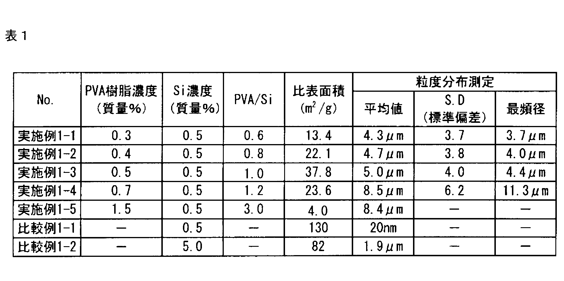
[SEM表面写真による二次粒子の観察]
実施例1-1~実施例1-4で得られた二次粒子の粉末の試料を、走査型電子顕微鏡(FE-SEM)(S-5200型、日立ハイテクノロジーズ製)の試料台に固定し、Ptスパッタコーティングを行い、加速電圧2kV及び試料傾斜角度40°で表面観察を行った。
実施例1-1~実施例1-4で得られた二次粒子の粉末の試料を、走査型電子顕微鏡(FE-SEM)(S-5200型、日立ハイテクノロジーズ製)の試料台に固定し、Ptスパッタコーティングを行い、加速電圧2kV及び試料傾斜角度40°で表面観察を行った。
実施例1-1~実施例1-4についてのSEM写真(撮影倍率×4000)を、図7-1~図7-4に示す。また、実施例2-2及び実施例2-4についてのSEM写真(撮影倍率×3000)を、図10及び図11に示す。
[粒度分布測定結果、比表面積測定結果及びSEM表面写真による観察結果に基づく評価]
(実施例1-1~実施例1-4、比較例1-1及び比較例1-2について)
図6-1~図6-4を参照すると、実施例1-1~実施例1-4で得られた二次粒子の粒度分布は0.4μm~20μmであり、粒度分布として良好であることが理解できる。また、図6-1~図6-4、図7-1~図7-4及び表1から明らかなように、実施例1-1~実施例1-5で得られた二次粒子の平均粒子径は4.3μm~8.5μmであり、比表面積は4.0~37.8m2/gであった。
(実施例1-1~実施例1-4、比較例1-1及び比較例1-2について)
図6-1~図6-4を参照すると、実施例1-1~実施例1-4で得られた二次粒子の粒度分布は0.4μm~20μmであり、粒度分布として良好であることが理解できる。また、図6-1~図6-4、図7-1~図7-4及び表1から明らかなように、実施例1-1~実施例1-5で得られた二次粒子の平均粒子径は4.3μm~8.5μmであり、比表面積は4.0~37.8m2/gであった。
比較例1-1の平均粒子径20nmのシリコン系粒子の比表面積は130m2/gであるのに対して、実施例1-1~実施例1-5で得られた二次粒子はそれよりも小さい比表面積を示すことから、二次粒子は、複数の一次粒子(シリコン粒子)がポリビニルアルコールに覆われて二次粒子化された構造を有することが理解できる。比較例1-2の二次粒子は比表面積が82m2/gであることから、比較例1-1のシリコン粒子自体の比表面積と大差ないことが理解できる。一方で、実施例1-1~実施例1-5で得られた二次粒子の比表面積(4.0~37.8m2/g)は、大幅に小さくなったことが理解できる。
(実施例2-1~実施例2-4、比較例1-1及び比較例1-2について)
実施例2-1~実施例2-3で得られた二次粒子の平均粒子径は、それぞれ、6.5μm、9.8μm、及び3.3μmであった。
実施例2-1~実施例2-3で得られた二次粒子の平均粒子径は、それぞれ、6.5μm、9.8μm、及び3.3μmであった。
比表面積については、炭化前(焼成前)の二次粒子(実施例2-2(図10))の比表面積が22m2/gであるのに対して、炭化後(焼成後)の二次粒子(実施例2-4(図11))の比表面積は41m2/gであった。したがって、比表面積は炭化(焼成)によって若干増加していることが理解できる。
[FE-STEM断面写真による二次粒子の観察]
実施例1-4で得られた二次粒子をサンプルとして、集束イオンビーム(FIB)加工により作製した薄片化試料(膜厚約100nm)について、FE-STEMにより二次電子像観察、走査透過電子像観察を行った。FE-STEM写真を図8-1~図8-3に示す。
実施例1-4で得られた二次粒子をサンプルとして、集束イオンビーム(FIB)加工により作製した薄片化試料(膜厚約100nm)について、FE-STEMにより二次電子像観察、走査透過電子像観察を行った。FE-STEM写真を図8-1~図8-3に示す。
実施例2-4で得られた二次粒子のFE-STEM写真を図12、及び図13-1~図13-3に示す。
[FE-STEM断面写真による二次粒子の観察に基づく評価]
(実施例1-4について)
図8-1(撮影倍率×50,000)に示すように、実施例1-4で得られた二次粒子の周縁部には、シリコン粒子とポリビニルアルコールが密に存在する一方で、中心部には、これらが疎に存在し、空孔(A:写真の白色部分)が存在していることが理解できる。
(実施例1-4について)
図8-1(撮影倍率×50,000)に示すように、実施例1-4で得られた二次粒子の周縁部には、シリコン粒子とポリビニルアルコールが密に存在する一方で、中心部には、これらが疎に存在し、空孔(A:写真の白色部分)が存在していることが理解できる。
図8-2と図8-3とは、図8-1のe部付近と、図8-1のf部付近のそれぞれの部分拡大写真である(撮影倍率×200,000)。
図8-2で示されるように、二次粒子の周縁部において、ポリビニルアルコール(C:写真のグレー部分)でコーティングされていることが理解でき、二次粒子の周縁部において、複数の一次粒子(シリコン粒子)(B:写真の黒色部分)がポリビニルアルコール(C:写真のグレー部分)を介して互いに結合していることが理解できる。
また、図8-3で示されるように、二次粒子の中心部において、複数の一次粒子(シリコン粒子)(B:黒色部分)が、ポリビニルアルコール(C:写真のグレー部分)を介して互いに結合していることが理解できる。また、図8-3において幾つかの空孔(A:写真の白色部分)が観察される。
(実施例2-4について)
二次粒子が仮に、炭素の密度が1.6g/cm3であり、Siの密度が2.3g/cm3であり、炭素が周縁部全体にのみに存在すると仮定すると、球換算平均直径の9%程度(二次粒子が直径10μmであるならば約0.9μm)の厚みを有するカーボン(導電性炭素材料)が、二次粒子の周縁部全体に在る粒子であることになる。
二次粒子が仮に、炭素の密度が1.6g/cm3であり、Siの密度が2.3g/cm3であり、炭素が周縁部全体にのみに存在すると仮定すると、球換算平均直径の9%程度(二次粒子が直径10μmであるならば約0.9μm)の厚みを有するカーボン(導電性炭素材料)が、二次粒子の周縁部全体に在る粒子であることになる。
しかし、実施例2-8について確認すると、図12のFE-STEM写真で示すように、炭素は二次粒子の内部にも存在するため、粒子の周縁部全体に在るカーボン(導電性炭素材料)の厚みは薄くなり、図12のFE-STEM写真の観察結果からは、二次粒子の直径600nmに対して、周縁部にあるカーボン(導電性炭素材料)の厚みは30nm(球換算平均直径の約5%)である。
図13-1(撮影倍率×5,000)に示すように、実施例2-4で得られた二次粒子の周縁部は、シリコン粒子及びカーボン(導電性炭素材料)が密に存在し、中心部は疎に存在し、空孔(写真の白色部分)が存在していることが理解できる。
図13-2及び図13-3はそれぞれ、図13-1のb-1部付近及びb-2部付近の部分拡大写真である(撮影倍率×30,000)。
図13-2で示されるように、周縁部はカーボン(写真のグレー部分)でコーティングされていることが理解でき、二次粒子の周縁部において、複数の一次粒子(シリコン粒子)(写真の黒色部分)がカーボン(写真のグレー部)を介して互いに結合していることが理解できる。
図13-3で示されるように、二次粒子の中心部において、複数の一次粒子(シリコン粒子)(写真の黒色部分)がカーボン(写真のグレー部分)を介して互いに結合していることが理解できる。また、図13-3において幾つかの空孔(写真の白色部分)が観察される。
[サイクル特性]
(実施例1-1について)
(1)負極(作用電極)の作製
実施例1-1で得られた二次粒子(電極活物質二次粒子):85質量%、アセチレンブラック(電気化学工業製のデンカブラック):3質量%、及びバインダー(ポリアミド系樹脂):12質量%を、分散媒としてのN-メチル-2-ピロリドンに分散させてスラリーを得て、このスラリーを撹拌装置(「あわとり練太郎」(シンキー製))で撹拌して、負極層を作製した。
(実施例1-1について)
(1)負極(作用電極)の作製
実施例1-1で得られた二次粒子(電極活物質二次粒子):85質量%、アセチレンブラック(電気化学工業製のデンカブラック):3質量%、及びバインダー(ポリアミド系樹脂):12質量%を、分散媒としてのN-メチル-2-ピロリドンに分散させてスラリーを得て、このスラリーを撹拌装置(「あわとり練太郎」(シンキー製))で撹拌して、負極層を作製した。
次に、厚み20μmの銅箔からなる集電体上に、アプリケーターを用いて上記負極層を20μmの厚さに塗布し、熱風乾燥機において、80℃で3時間にわたって乾燥し、さらに、120℃で5時間にわたって乾燥し、そしてロールプレス機によりプレスして、負極電極を作製した。作製した負極電極を、直径14mmの円形に打ち抜いて、負極(作用電極)とした。
得られた負極の材料特性値を下記の表2に示す。
(2)参照電極の作製
金属リチウム箔を、直径14mmの円形に打ち抜いて、参照電極とした。
金属リチウム箔を、直径14mmの円形に打ち抜いて、参照電極とした。
(3)負極半電池の作製
得られた負極(作用電極)と参照電極との間に、セパレータとしての多孔質ポリエチレンフィルム(東燃化学(株)社製のE-20MMS)を挟み込んで負極半電池積層体を得て、この電池積層体を電池ケースに収納し、そして電解液を含浸させて、実施例1-1の負極半電池を得た。なお、作業は、アルゴンドライボックス中で行った。また、電解液は、エチレンカーボネートとエチルメチルカーボネートとの70:30(体積比)混合溶媒に、1mol/LのLiPF6を溶解した溶液であった。
得られた負極(作用電極)と参照電極との間に、セパレータとしての多孔質ポリエチレンフィルム(東燃化学(株)社製のE-20MMS)を挟み込んで負極半電池積層体を得て、この電池積層体を電池ケースに収納し、そして電解液を含浸させて、実施例1-1の負極半電池を得た。なお、作業は、アルゴンドライボックス中で行った。また、電解液は、エチレンカーボネートとエチルメチルカーボネートとの70:30(体積比)混合溶媒に、1mol/LのLiPF6を溶解した溶液であった。
(4)測定
充放電試験は、充放電装置(北斗電工(株)社製)を用い、充電及び放電時の電流密度を0.1mA/cm2又は1mA/cm2として行った。なお、充電は、初期電圧から、リチウム金属電位までCC-CV法(定電流定電圧法)による充電を行い、放電は、リチウム金属電位-0Vからリチウム金属電位-1Vまで、CC法(定電流法)によって行った。充電は、1Cレートの定電流定電圧条件で電池電圧が0.01Vに達するまで行ない、放電は、1Cレートの定電流条件で電池電圧が1Vに達するまで行なった。この充放電サイクルを10サイクル繰り返し、その後の放電容量を測定した。その結果を図9に示す。
充放電試験は、充放電装置(北斗電工(株)社製)を用い、充電及び放電時の電流密度を0.1mA/cm2又は1mA/cm2として行った。なお、充電は、初期電圧から、リチウム金属電位までCC-CV法(定電流定電圧法)による充電を行い、放電は、リチウム金属電位-0Vからリチウム金属電位-1Vまで、CC法(定電流法)によって行った。充電は、1Cレートの定電流定電圧条件で電池電圧が0.01Vに達するまで行ない、放電は、1Cレートの定電流条件で電池電圧が1Vに達するまで行なった。この充放電サイクルを10サイクル繰り返し、その後の放電容量を測定した。その結果を図9に示す。
(実施例1-4、実施例1-6、及び実施例1-7について)
それぞれ実施例1-4、実施例1-6、及び実施例1-7で得られた二次粒子を用いたこと以外は、実施例1-1の場合と同様な方法で、負極半電池を作製して、充放電試験(10サイクル)を行った。得られた負極の材料特性値を下記の表2に示す。サイクル特性の結果を図9に示す。
それぞれ実施例1-4、実施例1-6、及び実施例1-7で得られた二次粒子を用いたこと以外は、実施例1-1の場合と同様な方法で、負極半電池を作製して、充放電試験(10サイクル)を行った。得られた負極の材料特性値を下記の表2に示す。サイクル特性の結果を図9に示す。
(比較例1-1について)
比較例1-1で得られたシリコン粒子:50質量%、アセチレンブラック:40質量%、バインダー(ポリフッ化ビニリデン(PVDF)):10質量%を用いたこと以外は、実施例1-1の場合と同様な方法で、負極半電池を作製して、充放電試験(10サイクル)を行った。得られた負極の材料特性値を下記の表2に示す。サイクル特性の結果を図9に示す。
比較例1-1で得られたシリコン粒子:50質量%、アセチレンブラック:40質量%、バインダー(ポリフッ化ビニリデン(PVDF)):10質量%を用いたこと以外は、実施例1-1の場合と同様な方法で、負極半電池を作製して、充放電試験(10サイクル)を行った。得られた負極の材料特性値を下記の表2に示す。サイクル特性の結果を図9に示す。
[サイクル特性評価]
図9に示すように、実施例1-1、1-4、1-6、及び1-7は初期放電容量が高く、2サイクル以降の放電容量の低下がなく、10サイクルまで良好なサイクル特性が得られることが理解できる。一方、比較例1-1は、初期放電容量が低く、2サイクル以降の放電容量の低下があり、10サイクルまで良好なサイクル特性が得られないことが理解できる。
図9に示すように、実施例1-1、1-4、1-6、及び1-7は初期放電容量が高く、2サイクル以降の放電容量の低下がなく、10サイクルまで良好なサイクル特性が得られることが理解できる。一方、比較例1-1は、初期放電容量が低く、2サイクル以降の放電容量の低下があり、10サイクルまで良好なサイクル特性が得られないことが理解できる。

[細孔径分布測定]
実施例1-5及び実施例1-8、比較例1-2、並びに実施例2-4で得られた二次粒子の細孔径(ポアサイズ)分布を、水銀圧入法によるポロシメータ((株)島津製作所製、オートポアIV)によって測定をした。水銀圧入法の試験条件は以下のとおりである。
実施例1-5及び実施例1-8、比較例1-2、並びに実施例2-4で得られた二次粒子の細孔径(ポアサイズ)分布を、水銀圧入法によるポロシメータ((株)島津製作所製、オートポアIV)によって測定をした。水銀圧入法の試験条件は以下のとおりである。
(1)使用ガラスセル:No.61707-0949((株)島津製作所製)
(2)水銀と試料の接触角:140°
(3)水銀の表面張力:485mN/m
(4)水銀の密度:13.5g/cm3
(2)水銀と試料の接触角:140°
(3)水銀の表面張力:485mN/m
(4)水銀の密度:13.5g/cm3
細孔径分布測定結果を図14~図17に示す。ここで、図14~図17はそれぞれ下記の実施例及び比較例の二次粒子の細孔径分布の測定結果を示す図である:
図14:実施例1-5
図15:比較例1-2
図16:実施例1-5及び実施例1-8
図17:実施例2-4
図14:実施例1-5
図15:比較例1-2
図16:実施例1-5及び実施例1-8
図17:実施例2-4
図14~17において、横軸(細孔径)(μm)は、細孔の半径の対数を表し、かつ縦軸(mL/g)は、その半径以上の半径を有する細孔の単位質量(通常は1g)当たりの細孔体積の合計を細孔半径の対数で微分した値(微分細孔容量(対数)(mL/g)を表す。
[細孔径分布の評価]
(実施例1-5、及び比較例1-2について)
図14によれば、実施例1-5で得られた二次粒子、すなわち、ポリビニールアルコール(PVA)を炭化する前の二次粒子のピークトップは1.5μmであった。また、図15によれば、比較例1-2で得られたシリコン系二次粒子、すなわちポリビニルアルコール(PVA)を有さないシリコン二次粒子のピークトップは、0.02μmであった。図14と図15との結果を比較すると、ポリビニルアルコール(PVA)を有さないと小さな細孔が形成されやすいことがわかる。
(実施例1-5、及び比較例1-2について)
図14によれば、実施例1-5で得られた二次粒子、すなわち、ポリビニールアルコール(PVA)を炭化する前の二次粒子のピークトップは1.5μmであった。また、図15によれば、比較例1-2で得られたシリコン系二次粒子、すなわちポリビニルアルコール(PVA)を有さないシリコン二次粒子のピークトップは、0.02μmであった。図14と図15との結果を比較すると、ポリビニルアルコール(PVA)を有さないと小さな細孔が形成されやすいことがわかる。
(実施例2-4について)
図17によれば、実施例2-4で得られた二次粒子、すなわち、フェノール樹脂を炭化した後の二次粒子のピークトップは、2.5μmであった。
図17によれば、実施例2-4で得られた二次粒子、すなわち、フェノール樹脂を炭化した後の二次粒子のピークトップは、2.5μmであった。
(実施例3)
(炭素繊維の作製)
下記のようにして炭素繊維を作製した。熱可塑性樹脂として高密度ポリエチレン(株式会社プライムポリマー社製、ハイゼックス5000SR)90質量部と、熱可塑性炭素前駆体としてメソフェーズピッチAR-MPH(三菱ガス化学株式会社製)10質量部を同方向二軸押出機(東芝機械株式会社製TEM-26SS、バレル温度310℃、窒素気流下)で溶融混練して混合物を作製した。この条件で得られた混合物の、熱可塑性炭素前駆体の熱可塑性樹脂中への分散径は0.05~2μmであった。また、この混合物を300℃で10分間保持したが、熱可塑性炭素前駆体の凝集は認められず、分散径は0.05~2μmであった。
(炭素繊維の作製)
下記のようにして炭素繊維を作製した。熱可塑性樹脂として高密度ポリエチレン(株式会社プライムポリマー社製、ハイゼックス5000SR)90質量部と、熱可塑性炭素前駆体としてメソフェーズピッチAR-MPH(三菱ガス化学株式会社製)10質量部を同方向二軸押出機(東芝機械株式会社製TEM-26SS、バレル温度310℃、窒素気流下)で溶融混練して混合物を作製した。この条件で得られた混合物の、熱可塑性炭素前駆体の熱可塑性樹脂中への分散径は0.05~2μmであった。また、この混合物を300℃で10分間保持したが、熱可塑性炭素前駆体の凝集は認められず、分散径は0.05~2μmであった。
次いで、上記混合物をシリンダー式単孔紡糸機により、紡糸温度390℃の条件で、繊維径100μmの長繊維を作製した。
次に、この前駆体繊維からなる30g/m2の目付けの不織布を湿式法により調製し、これをステンレス製の金網に挟み込み、215℃の熱風乾燥機の中で3時間保持させることにより、安定化樹脂組成物を作製した。なお、この際使用の金網は、目開きが1.46mm、直径が0.35mmの綾織りのステンレス製金網を使用し、金網の間隔は、10mmであった。
次に、真空ガス置換炉中で、窒素ガス雰囲気下で加熱することにより、繊維状炭素前駆体からなる不織布を作製した。加熱条件は、昇温速度5℃/分にて500℃まで昇温後、同温度で60分間保持を行った。
この繊維状炭素前駆体からなる不織布をイオン交換水中に加え、ミキサーで2分間粉砕することにより、濃度0.1重量%の繊維状炭素前駆体を分散させた予備分散液を作製した。この予備分散液を、湿式ジェットミル(株式会社スギノマシン社製、スターバーストラボHJP-17007、使用チャンバー:シングルノズルチャンバー)を用いて、ノズル径0.17mm、処理圧力100MPaにより、処理を10回繰り返すことによって、繊維状炭素前駆体の分散させた液を作製した。
次いで、得られた溶媒液を濾過することによって、繊維状炭素前駆体を分散させた材料を作製した。
この繊維状炭素前駆体を分散させた材料をアルゴンガス雰囲気下、室温から3時間で3000℃まで昇温することで、黒鉛化した炭素繊維を作製した。得られた炭素繊維の繊維径は300~600nmであり、炭素繊維が融着した繊維集合体がほとんどなく、非常に分散性に優れた炭素繊維であった。
(二次粒子の作製)
(電極(正極活物質二次粒子の作製)
正極活物質の前駆体であるマンガン、コバルト及びニッケルを含む炭素繊維複合酸化物粒子(前駆体酸化物粒子)は、以下のように作製した。
(電極(正極活物質二次粒子の作製)
正極活物質の前駆体であるマンガン、コバルト及びニッケルを含む炭素繊維複合酸化物粒子(前駆体酸化物粒子)は、以下のように作製した。
硝酸(HNO3)水溶液及び35wt%過酸化水素水(H2O2)を1:3の体積比率で混合し、上記のように作製した炭素繊維を、この水溶液中に48時間にわたって浸漬した後で、超音波照射を実施した。その後、洗浄と120℃での乾燥を行った。
その後、硫酸マンガン五水和物(和光純薬工業社製、一級試薬)13.64g、硝酸コバルト六水和物(和光純薬工業社製、特級試薬)2.06g、及び硝酸ニッケル六水和物(和光純薬工業社製、特級試薬)5.04gを、100mlの蒸留水に溶解し、金属塩水溶液を作製した。この金属塩水溶液に、酸処理を実施した炭素繊維を金属塩水溶液に対して1%の割合で添加した。
次に、炭酸水素ナトリウム(和光純薬工業社製、特級試薬)26.9gを1000mlの蒸留水に溶解し、炭酸水素ナトリウム水溶液を作製した。この炭酸水素ナトリウム水溶液を攪拌しながら、上記のように作製した炭素繊維を含む金属塩水溶液を滴下し、マンガン、コバルト及びニッケルを含む炭酸塩の粒子である乳白色の沈殿物を得た。
その後、吸引濾過し、120℃で乾燥した。さらに200℃で酸化処理をすることで、炭素繊維及びマンガン、コバルト及びニッケルを含む前駆体酸化物粒子を得た。
炭酸リチウム(和光純薬工業社製、特級試薬、融点723℃)3gと、上記作製した前駆体酸化物粒子3gを秤量し、メノウ乳鉢を用いて乾式混合した。
次に、この混合物を50mlのアルミナ坩堝に入れ、焼成炉内で熱処理を行った。熱処理は、大気中で、昇温速度5℃/minで650℃まで昇温、6時間熱処理し、その後、室温まで降温した。
得られた粉末を蒸留水で洗浄後、吸引濾過し、100℃で5時間乾燥することで実施例3の正極活物質二次粒子を得た。表面及び断面構造を観察したところ、粗密構造を有していることが確認された。また、一次粒子径がおよそ100nmであり、複数の一次粒子の間に上記導電性炭素繊維(CNF)が介在していることが確認された(図19参照)。
上記の方法で測定した正極活物質の組成は、Li[Li0.2Co0.07Ni0.17Mn0.56]O2であった。また、下記の方法で得たSEM写真を図19に示す。
(比較例3)
炭素繊維を入れないこと以外は実施例3に記載の方法でマンガン、コバルト及びニッケルを含む前駆体酸化物粒子を得た。
炭素繊維を入れないこと以外は実施例3に記載の方法でマンガン、コバルト及びニッケルを含む前駆体酸化物粒子を得た。
炭酸リチウム(和光純薬工業社製、特級試薬、融点723℃)3gと、上記作製した前駆体酸化物粒子3gを秤量し、メノウ乳鉢を用いて乾式混合した。
次に、この混合物を100mlのアルミナ坩堝に入れ、焼成炉内で熱処理を行った。熱処理は、大気中で、昇温速度10℃/minで900℃まで昇温、8時間熱処理し、その後、室温まで降温した。
得られた粉末を蒸留水で洗浄後、吸引濾過し、100℃で5時間乾燥することで比較例3の正極活物質を得た。表面及び断面構造を観察したところ、一次粒子径がおよそ200nmであり、内側(中心部)と外側(周縁部)が一様で粗密構造ではなかった。下記の方法で観察した正極活物質二次粒子の表面及び断面をそれぞれ図20(a)及び(b)に示す。
[SEM表面観察方法]
(1)水を含有したサンプルをSEMで観察するため、サンプルと同量の水で希釈した。
(2)試料台に貼ったカーボンテープ上に希釈液を滴下した後、自然乾燥させた。
(3)その後導電性付与のため、スパッタコーティング(Pt:0.5nm)を行った。
(4)装置FESEM S-5200型(日立ハイテクノロジーズ製)
(5)加速電圧3kVを用いて観察を行った。
(1)水を含有したサンプルをSEMで観察するため、サンプルと同量の水で希釈した。
(2)試料台に貼ったカーボンテープ上に希釈液を滴下した後、自然乾燥させた。
(3)その後導電性付与のため、スパッタコーティング(Pt:0.5nm)を行った。
(4)装置FESEM S-5200型(日立ハイテクノロジーズ製)
(5)加速電圧3kVを用いて観察を行った。
[SEM断面観察方法]
(1)パラフィルムの上に2%寒天を滴下し、サンプルを固定した(寒天包埋方法)。
(2)余分な寒天を切り落とし、適当な大きさに細切した。
(3)50%エタノールで10分間脱水した。
(4)70%エタノールで10分間脱水した。
(5)80%エタノールで20分間脱水した。
(6)90%エタノールで30分間脱水した。
(7)95%エタノールで30分間脱水した。
(8)100%エタノールで30分間脱水した。
(9)QY-1(n-ブチルグリシジルエーテルヤーン)に30分間置換した。
(10)QY-1:Epon(エポキシ樹脂)=1:1に30分間置換した。
(11)QY-1:Epon=1:2に30分間にわたって置換した。
(12)Eponにて一晩にわたって置換した。
(13)シリコン製カプセルに移し、Epon(B-only)で包埋し45℃で6時間、60℃3日間硬化させた。
(14)ウルトラミクロトームで50~100nm厚に薄切し、カーボン支持膜を張った銅グリッドに載台した。
(15)観察・撮影は透過型電子顕微鏡TECNAI G2(FEI社製 加速電圧120kV)で実施した。
(16)微細構造観察はJEM-2010(日本電子製 加速電圧200kV)で実施した。
(1)パラフィルムの上に2%寒天を滴下し、サンプルを固定した(寒天包埋方法)。
(2)余分な寒天を切り落とし、適当な大きさに細切した。
(3)50%エタノールで10分間脱水した。
(4)70%エタノールで10分間脱水した。
(5)80%エタノールで20分間脱水した。
(6)90%エタノールで30分間脱水した。
(7)95%エタノールで30分間脱水した。
(8)100%エタノールで30分間脱水した。
(9)QY-1(n-ブチルグリシジルエーテルヤーン)に30分間置換した。
(10)QY-1:Epon(エポキシ樹脂)=1:1に30分間置換した。
(11)QY-1:Epon=1:2に30分間にわたって置換した。
(12)Eponにて一晩にわたって置換した。
(13)シリコン製カプセルに移し、Epon(B-only)で包埋し45℃で6時間、60℃3日間硬化させた。
(14)ウルトラミクロトームで50~100nm厚に薄切し、カーボン支持膜を張った銅グリッドに載台した。
(15)観察・撮影は透過型電子顕微鏡TECNAI G2(FEI社製 加速電圧120kV)で実施した。
(16)微細構造観察はJEM-2010(日本電子製 加速電圧200kV)で実施した。
(リチウムイオン二次電池用正極活物質の電気化学的評価)
上記実施例3及び比較例3で得られた正極活物質二次粒子を用いて以下の手順で評価セルを作製し、サイクル特性の評価を行った。
上記実施例3及び比較例3で得られた正極活物質二次粒子を用いて以下の手順で評価セルを作製し、サイクル特性の評価を行った。
実施例3及び比較例3で得られた正極活物質75質量部、導電材としてアセチレンブラック(電気化学工業製のデンカブラック)20質量部、及びバインダーとしてポリテトラフルオロエチレン(ダイキン社製、F104)5質量部を混合し、活物質重量が所定量となるように電極シートを作製した。
作製した電極シートを直径17mmの円形に打ち抜いた後、導電性ペースト(日本黒鉛工業社製、バニーハイトT-602)を用いて20μmのAl箔に接着し、170℃で10時間真空乾燥し、電池特性評価用の正極とした。作製した正極の物性を表3に示す。
正極には、上記作製した正極、負極には厚さ200μmの金属リチウム箔(本荘ケミカル社製)、電解液には、1mol/lのLiPF6、エチレンカーボネートとエチルメチルカーボネート(体積比30:70)(キシダ化学社製)、セパレータにはガラス不織布(厚さ400μm)(アドバンテック社製、GB-100R)と市販ポリエチレン製微孔膜(厚さ20μm)とを重ね合わせたものを用いて評価セルを作製した。
作製したセルの25℃におけるサイクル特性を以下に示す試験条件にて評価した。
充電上限電圧を4.6V、放電下限電圧を2.0Vに設定して定電流・定電圧充電を行った。初期を電流密度:48mA/g(約5時間率)、引き続いて2サイクル目を、48mA/g、3サイクル目を120mA/g、4サイクル目を240mA/g、5サイクル目を480mA/gで行った、次に充電上限電圧を4.8V、放電下限電圧を2.0Vとして、6~10サイクル目まで電流密度:48mA/gで試験を行った。
作成されたセルの詳細を下記の表3に示す。また、測定された放電容量を図18に示す。
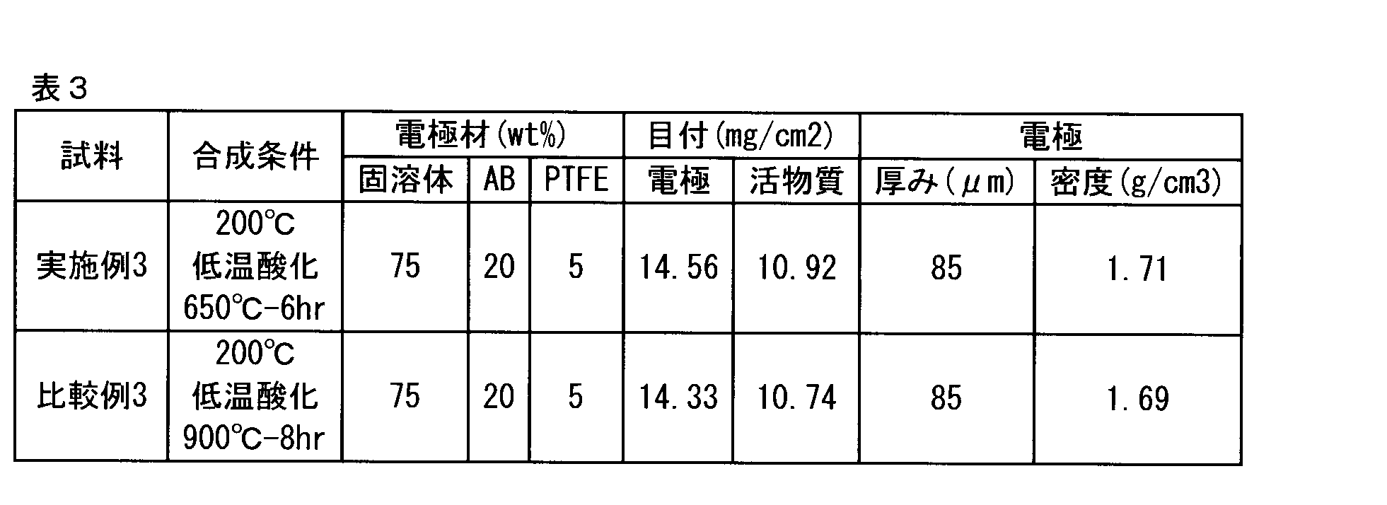
なお、本発明の実施態様としては、下記の態様を挙げることもできる。
(態様1)
本発明の電極活物質二次粒子(以下では単に「二次粒子」とする)は、複数の一次粒子と導電性炭素材料とを含んでなる二次粒子であって、複数の一次粒子の少なくとも一部の一次粒子が、その導電性炭素材料を介して互いに結合している、二次粒子である。
(態様2)
態様1の二次粒子において、本発明の二次粒子は、(a)上記複数の一次粒子と、上記導電性炭素材料と、溶媒とを混合する工程と、(b)上記(a)工程後に、噴霧乾燥する工程と、を含む方法によって得られる。
(態様3)
態様2の二次粒子において、本発明の二次粒子が、(c)上記(b)工程後に、500℃~1400℃で焼成する工程、を更に含む方法によって得られる。
(態様4)
本発明の二次粒子は、複数の一次粒子と導電性炭素材料とを含んでなる二次粒子であって、複数の一次粒子と導電性炭素材料とが、二次粒子の周縁部で密に存在し、かつ、二次粒子の内側で疎に存在する、二次粒子である。
(態様5)
態様4の二次粒子において、二次粒子の上記内側で、少なくとも2つの空孔が連続して存在し、空孔の大きさが0.02μm~0.4μmである。
(態様6)
本発明の二次粒子は、複数の一次粒子と導電性炭素材料とを含んでなる二次粒子であって、二次粒子のBET比表面積が0.2m2/g~100m2/gである、二次粒子である。
(態様7)
態様1~態様6のいずれか1の態様の二次粒子において、導電性炭素材料が炭素原子を含むポリマー材料である。
(態様8)
態様1~態様7のいずれか1の態様の二次粒子において、複数の一次粒子の平均一次粒子径が5nm以上300nm以下である。
(態様9)
態様1~態様8のいずれか1の態様の二次粒子において、二次粒子の平均粒子径が40nm以上100μm以下である。
(態様10)
態様1~態様9のいずれか1の態様の二次粒子において、複数の一次粒子がシリコン系粒子を含む。
(態様11)
本発明の負極活物質は、態様10の二次粒子を含む負極活物質である。
(態様12)
本発明の負極層は、態様11の負極活物質と、導電助剤と、バインダーとを含む負極層である。
(態様13)
本発明の負極は、態様12の負極層と集電体とからなる負極である。
(態様14)
態様1~態様9のいずれか1の態様の二次粒子において、複数の一次粒子が、オリビン系化合物、ポリアニオン系化合物、ケイ酸塩系化合物及びLi過剰固溶体系化合物からなる群から選択される少なくとも1種の化合物を含有する一次粒子を含む。
(態様15)
本発明の正極用活物質は、態様14の二次粒子を含む正極活物質である。
(態様16)
本発明の正極層は、態様15の正極活物質と、導電助剤と、バインダーとを含む正極層である。
(態様17)
本発明の正極は、態様16の正極層と集電体とからなる正極である。
(態様18)
本発明の非水電解質二次電池は、態様13の負極及び/又は態様17の正極を含む非水電解質二次電池である。
(態様19)
本発明の二次粒子は、複数の一次粒子と導電性炭素材料とを含んでなる二次粒子であって、水銀圧入法による上記二次粒子の細孔分布曲線において、0.2μm超10μm以下のピークトップが存在する、二次粒子である。
(態様20)
態様19の二次粒子において、二次粒子の球換算平均直径の0.5%~20%の厚みを有する導電性炭素材料の少なくとも一部が二次粒子の周縁部に在る。
(態様21)
態様19又は態様20の二次粒子において、複数の一次粒子の少なくとも一部が、二次粒子の周縁部に在る。
(態様22)
態様19~態様21のいずれか1の態様において、本発明の二次粒子は、(a)上記複数の一次粒子と、上記導電性炭素材料と、溶媒とを混合する工程と、(b)上記(a)工程後に、噴霧乾燥する工程と、を含む方法によって得られる。
(態様23)
態様22において、本発明の二次粒子は、(c)上記(b)工程後に、500℃~1400℃で焼成する工程、を更に含む方法によって得られる。
(態様24)
態様19~態様23のいずれか1の態様の二次粒子において、導電性炭素材料が炭素原子を含むポリマー材料である。
(態様25)
態様19~態様24のいずれか1の態様の二次粒子において、複数の一次粒子の平均一次粒子径が5nm以上300nm以下である。
(態様26)
態様19~態様25のいずれか1の態様の二次粒子において、二次粒子の平均粒子径が40nm以上100μm以下である。
(態様27)
態様19~態様26のいずれか1の態様の二次粒子において、複数の一次粒子がシリコン系粒子を含む。
(態様28)
本発明の負極活物質は、態様27の二次粒子を含む負極活物質である。
(態様29)
本発明の負極層は、態様28の負極活物質と、導電助剤と、バインダーとを含む負極層である。
(態様30)
本発明の負極は、態様29の負極層と集電体とからなる負極である。
(態様31)
態様19~態様26のいずれか1の態様の二次粒子において、複数の一次粒子が、オリビン系化合物、ポリアニオン系化合物、ケイ酸塩系化合物及びLi過剰固溶体系化合物からなる群から選択される少なくとも1種の化合物を含有する一次粒子を含む。
(態様32)
本発明の正極活物質は、態様31の二次粒子を含む正極活物質である。
(態様33)
本発明の正極層は、態様32の正極活物質と、導電助剤と、バインダーとを含む正極層である。
(態様34)
本発明の正極は、態様33の正極層と集電体とからなる正極である。
(態様35)
本発明の非水電解質二次電池は、態様30の負極及び/又は態様34の正極を含む非水電解質二次電池である。
本発明の電極活物質二次粒子(以下では単に「二次粒子」とする)は、複数の一次粒子と導電性炭素材料とを含んでなる二次粒子であって、複数の一次粒子の少なくとも一部の一次粒子が、その導電性炭素材料を介して互いに結合している、二次粒子である。
(態様2)
態様1の二次粒子において、本発明の二次粒子は、(a)上記複数の一次粒子と、上記導電性炭素材料と、溶媒とを混合する工程と、(b)上記(a)工程後に、噴霧乾燥する工程と、を含む方法によって得られる。
(態様3)
態様2の二次粒子において、本発明の二次粒子が、(c)上記(b)工程後に、500℃~1400℃で焼成する工程、を更に含む方法によって得られる。
(態様4)
本発明の二次粒子は、複数の一次粒子と導電性炭素材料とを含んでなる二次粒子であって、複数の一次粒子と導電性炭素材料とが、二次粒子の周縁部で密に存在し、かつ、二次粒子の内側で疎に存在する、二次粒子である。
(態様5)
態様4の二次粒子において、二次粒子の上記内側で、少なくとも2つの空孔が連続して存在し、空孔の大きさが0.02μm~0.4μmである。
(態様6)
本発明の二次粒子は、複数の一次粒子と導電性炭素材料とを含んでなる二次粒子であって、二次粒子のBET比表面積が0.2m2/g~100m2/gである、二次粒子である。
(態様7)
態様1~態様6のいずれか1の態様の二次粒子において、導電性炭素材料が炭素原子を含むポリマー材料である。
(態様8)
態様1~態様7のいずれか1の態様の二次粒子において、複数の一次粒子の平均一次粒子径が5nm以上300nm以下である。
(態様9)
態様1~態様8のいずれか1の態様の二次粒子において、二次粒子の平均粒子径が40nm以上100μm以下である。
(態様10)
態様1~態様9のいずれか1の態様の二次粒子において、複数の一次粒子がシリコン系粒子を含む。
(態様11)
本発明の負極活物質は、態様10の二次粒子を含む負極活物質である。
(態様12)
本発明の負極層は、態様11の負極活物質と、導電助剤と、バインダーとを含む負極層である。
(態様13)
本発明の負極は、態様12の負極層と集電体とからなる負極である。
(態様14)
態様1~態様9のいずれか1の態様の二次粒子において、複数の一次粒子が、オリビン系化合物、ポリアニオン系化合物、ケイ酸塩系化合物及びLi過剰固溶体系化合物からなる群から選択される少なくとも1種の化合物を含有する一次粒子を含む。
(態様15)
本発明の正極用活物質は、態様14の二次粒子を含む正極活物質である。
(態様16)
本発明の正極層は、態様15の正極活物質と、導電助剤と、バインダーとを含む正極層である。
(態様17)
本発明の正極は、態様16の正極層と集電体とからなる正極である。
(態様18)
本発明の非水電解質二次電池は、態様13の負極及び/又は態様17の正極を含む非水電解質二次電池である。
(態様19)
本発明の二次粒子は、複数の一次粒子と導電性炭素材料とを含んでなる二次粒子であって、水銀圧入法による上記二次粒子の細孔分布曲線において、0.2μm超10μm以下のピークトップが存在する、二次粒子である。
(態様20)
態様19の二次粒子において、二次粒子の球換算平均直径の0.5%~20%の厚みを有する導電性炭素材料の少なくとも一部が二次粒子の周縁部に在る。
(態様21)
態様19又は態様20の二次粒子において、複数の一次粒子の少なくとも一部が、二次粒子の周縁部に在る。
(態様22)
態様19~態様21のいずれか1の態様において、本発明の二次粒子は、(a)上記複数の一次粒子と、上記導電性炭素材料と、溶媒とを混合する工程と、(b)上記(a)工程後に、噴霧乾燥する工程と、を含む方法によって得られる。
(態様23)
態様22において、本発明の二次粒子は、(c)上記(b)工程後に、500℃~1400℃で焼成する工程、を更に含む方法によって得られる。
(態様24)
態様19~態様23のいずれか1の態様の二次粒子において、導電性炭素材料が炭素原子を含むポリマー材料である。
(態様25)
態様19~態様24のいずれか1の態様の二次粒子において、複数の一次粒子の平均一次粒子径が5nm以上300nm以下である。
(態様26)
態様19~態様25のいずれか1の態様の二次粒子において、二次粒子の平均粒子径が40nm以上100μm以下である。
(態様27)
態様19~態様26のいずれか1の態様の二次粒子において、複数の一次粒子がシリコン系粒子を含む。
(態様28)
本発明の負極活物質は、態様27の二次粒子を含む負極活物質である。
(態様29)
本発明の負極層は、態様28の負極活物質と、導電助剤と、バインダーとを含む負極層である。
(態様30)
本発明の負極は、態様29の負極層と集電体とからなる負極である。
(態様31)
態様19~態様26のいずれか1の態様の二次粒子において、複数の一次粒子が、オリビン系化合物、ポリアニオン系化合物、ケイ酸塩系化合物及びLi過剰固溶体系化合物からなる群から選択される少なくとも1種の化合物を含有する一次粒子を含む。
(態様32)
本発明の正極活物質は、態様31の二次粒子を含む正極活物質である。
(態様33)
本発明の正極層は、態様32の正極活物質と、導電助剤と、バインダーとを含む正極層である。
(態様34)
本発明の正極は、態様33の正極層と集電体とからなる正極である。
(態様35)
本発明の非水電解質二次電池は、態様30の負極及び/又は態様34の正極を含む非水電解質二次電池である。
本発明の二次粒子は、態様1~9及び態様19~26のうち2以上を任意に組み合わせてもよい。本発明の負極二次粒子は、態様10及び態様27を組み合わせてもよい。本発明の負極活物質は、態様11及び態様28を組み合わせてもよい。本発明の負極層は、態様12及び態様29を組み合わせてもよい。本発明の負極は、態様13及び態様30を組み合わせてもよい。本発明の正極二次粒子は、態様14及び態様31を組み合わせてもよい。本発明の正極活物質は、態様15及び態様32を組み合わせてもよい。本発明の正極層は、態様16及び態様33を組み合わせてもよい。本発明の正極は、態様17及び態様34を組み合わせてもよい。
10 集電体
11 電極活物質二次粒子(負極活物質)
11-1 一次粒子(シリコン系粒子)
12 集電体
13 電極活物質二次粒子(正極活物質)
13-1 一次粒子(Li過剰固溶体系化合物)
14 本発明の負極層
15 電解質層
16 正極層
17 集電体
18 本発明の正極層
19 負極層
20 集電体
100 本発明の負極
200 本発明の正極
300 本発明の非水電解質二次電池
400 正極
500 本発明の非水電解質二次電池
600 負極
700 本発明の非水電解質二次電池
A 空孔
B 一次粒子(シリコン系粒子)
C ポリビニルアルコール(PVA)
11 電極活物質二次粒子(負極活物質)
11-1 一次粒子(シリコン系粒子)
12 集電体
13 電極活物質二次粒子(正極活物質)
13-1 一次粒子(Li過剰固溶体系化合物)
14 本発明の負極層
15 電解質層
16 正極層
17 集電体
18 本発明の正極層
19 負極層
20 集電体
100 本発明の負極
200 本発明の正極
300 本発明の非水電解質二次電池
400 正極
500 本発明の非水電解質二次電池
600 負極
700 本発明の非水電解質二次電池
A 空孔
B 一次粒子(シリコン系粒子)
C ポリビニルアルコール(PVA)
Claims (15)
- 複数の一次粒子と導電性炭素材料とを含んでなる電極活物質二次粒子であって、
前記複数の一次粒子が、複数のシリコン系粒子又は正極活物質粒子であり、かつ
前記電極活物質二次粒子が、下記の(i)~(iv)の少なくとも1つを満している、電極活物質二次粒子:
(i)前記複数の一次粒子の間に前記導電性炭素材料が介在していること、
(ii)周縁部が中心部と比較して密であること、
(iii)BET比表面積が0.2m2/g~100m2/gであること、及び
(iv)水銀圧入法による細孔分布曲線において、0.2μm超10μm以下のピークトップを有すること。 - 少なくとも上記(i)を満たしている、請求項1に記載の二次粒子。
- 少なくとも上記(ii)を満たしている、請求項1又は2に記載の二次粒子。
- 少なくとも上記(iii)を満たしている、請求項1~3のいずれか一項に記載の二次粒子。
- 少なくとも上記(iv)を満たしている、請求項1~4のいずれか一項に記載の二次粒子。
- 前記複数の一次粒子の平均一次粒子径が、5nm以上300nm以下である、請求項1~5のいずれか一項に記載の二次粒子。
- 前記電極活物質二次粒子の平均粒子径が、40nm以上100μm以下である、請求項1~6のいずれか一項に記載の二次粒子。
- 前記導電性炭素材料が、カーボンブラック、グラファイト、アセチレンブラック、炭素繊維、炭素元素を含む前駆体を炭化させて得られる炭素材料、及びこれらの組み合わせからなる群より選択される、請求項1~7のいずれか一項に記載の二次粒子。
- 前記複数の一次粒子が、複数のシリコン系粒子であり、かつ前記導電性炭素材料が、炭素元素を含む前駆体を炭化させて得られる前記炭素材料である、請求項1~8のいずれか一項に記載の二次粒子。
- 請求項1~9のいずれか一項に記載の電極活物質二次粒子、導電助剤、及びバインダーを含有している、負極層。
- 前記複数の一次粒子が、複数の正極活物質粒子であり、かつ前記導電性炭素材料が、炭素繊維である、請求項1~7のいずれか一項に記載の二次粒子。
- 請求項1~8及び11のいずれか一項に記載の電極活物質二次粒子、導電助剤、及びバインダーを含有している、正極層。
- 請求項10に記載の負極層及び/又は請求項12に記載の正極層を具備している、非水電解質二次電池。
- (a)複数の一次粒子、導電性炭素材料及び/又はその前駆体、並びに溶媒を混合して、混合液を得、そして
(b)前記混合液を噴霧乾燥して、乾燥二次粒子を形成すること、
を含み、かつ前記複数の一次粒子が、複数のシリコン系粒子又は正極活物質粒子である、電極活物質二次粒子の製造方法。 - (c)前記乾燥二次粒子を500℃~1400℃で焼成すること、
を更に含む、請求項14に記載の方法。
Applications Claiming Priority (4)
| Application Number | Priority Date | Filing Date | Title |
|---|---|---|---|
| JP2013-074971 | 2013-03-29 | ||
| JP2013-074981 | 2013-03-29 | ||
| JP2013074981A JP2016136450A (ja) | 2013-03-29 | 2013-03-29 | 非水電解質二次電池用の複合二次粒子 |
| JP2013074971A JP2016136449A (ja) | 2013-03-29 | 2013-03-29 | 非水電解質二次電池用の複合二次粒子 |
Publications (1)
| Publication Number | Publication Date |
|---|---|
| WO2014157691A1 true WO2014157691A1 (ja) | 2014-10-02 |
Family
ID=51624647
Family Applications (1)
| Application Number | Title | Priority Date | Filing Date |
|---|---|---|---|
| PCT/JP2014/059335 Ceased WO2014157691A1 (ja) | 2013-03-29 | 2014-03-28 | 電極活物質二次粒子 |
Country Status (1)
| Country | Link |
|---|---|
| WO (1) | WO2014157691A1 (ja) |
Cited By (1)
| Publication number | Priority date | Publication date | Assignee | Title |
|---|---|---|---|---|
| WO2025017569A1 (en) * | 2023-07-17 | 2025-01-23 | Ola Electric Mobility Limited | A dry battery electrode, a lithium-ion battery and processes thereof |
Citations (5)
| Publication number | Priority date | Publication date | Assignee | Title |
|---|---|---|---|---|
| JP2003173777A (ja) * | 2001-12-07 | 2003-06-20 | Hitachi Metals Ltd | 非水系リチウム二次電池用正極活物質と導電助材の複合方法およびその複合材料、それを用いた正極および非水系リチウム二次電池 |
| WO2009081704A1 (ja) * | 2007-12-25 | 2009-07-02 | Kao Corporation | リチウム電池正極用複合材料 |
| JP2012043547A (ja) * | 2010-08-12 | 2012-03-01 | Hitachi Chem Co Ltd | リチウム二次電池用負極材、リチウムイオン二次電池用負極、およびリチウムイオン二次電池 |
| WO2013018721A1 (ja) * | 2011-07-29 | 2013-02-07 | 住友ベークライト株式会社 | リチウムイオン二次電池用炭素材の製造方法、リチウムイオン二次電池用炭素材、リチウムイオン二次電池用負極活物質、組成物、リチウムイオン二次電池負極材用炭素複合材、リチウムイオン二次電池用負極合剤、リチウムイオン二次電池用負極、及びリチウムイオン二次電池 |
| WO2013168785A1 (ja) * | 2012-05-10 | 2013-11-14 | 東洋インキScホールディングス株式会社 | リチウム二次電池正極用造粒粒子とその製造方法、合材インキ及びリチウム二次電池 |
-
2014
- 2014-03-28 WO PCT/JP2014/059335 patent/WO2014157691A1/ja not_active Ceased
Patent Citations (5)
| Publication number | Priority date | Publication date | Assignee | Title |
|---|---|---|---|---|
| JP2003173777A (ja) * | 2001-12-07 | 2003-06-20 | Hitachi Metals Ltd | 非水系リチウム二次電池用正極活物質と導電助材の複合方法およびその複合材料、それを用いた正極および非水系リチウム二次電池 |
| WO2009081704A1 (ja) * | 2007-12-25 | 2009-07-02 | Kao Corporation | リチウム電池正極用複合材料 |
| JP2012043547A (ja) * | 2010-08-12 | 2012-03-01 | Hitachi Chem Co Ltd | リチウム二次電池用負極材、リチウムイオン二次電池用負極、およびリチウムイオン二次電池 |
| WO2013018721A1 (ja) * | 2011-07-29 | 2013-02-07 | 住友ベークライト株式会社 | リチウムイオン二次電池用炭素材の製造方法、リチウムイオン二次電池用炭素材、リチウムイオン二次電池用負極活物質、組成物、リチウムイオン二次電池負極材用炭素複合材、リチウムイオン二次電池用負極合剤、リチウムイオン二次電池用負極、及びリチウムイオン二次電池 |
| WO2013168785A1 (ja) * | 2012-05-10 | 2013-11-14 | 東洋インキScホールディングス株式会社 | リチウム二次電池正極用造粒粒子とその製造方法、合材インキ及びリチウム二次電池 |
Cited By (1)
| Publication number | Priority date | Publication date | Assignee | Title |
|---|---|---|---|---|
| WO2025017569A1 (en) * | 2023-07-17 | 2025-01-23 | Ola Electric Mobility Limited | A dry battery electrode, a lithium-ion battery and processes thereof |
Similar Documents
| Publication | Publication Date | Title |
|---|---|---|
| JP7501623B2 (ja) | 複合炭素粒子およびその用途 | |
| KR101494715B1 (ko) | 리튬 이차 전지용 음극 활물질, 이의 제조 방법, 그리고 이를 포함하는 음극 및 리튬 이차 전지 | |
| KR101924035B1 (ko) | 실리콘-탄소 복합체, 이의 제조방법 및 이를 포함하는 음극 활물질 | |
| KR101807348B1 (ko) | 실리콘-탄소 복합체, 이의 제조방법 및 이를 포함하는 음극 활물질 | |
| JP6847667B2 (ja) | 非水電解質二次電池用負極活物質及び非水電解質二次電池 | |
| CN114144909A (zh) | 一种负极极片、包含该负极极片的电化学装置和电子装置 | |
| CN108352253A (zh) | 用于混合超级电容器-电池系统的活性碳粉 | |
| CN109314247B (zh) | 蓄电设备用电极材料、蓄电设备用电极以及蓄电设备 | |
| US20090191458A1 (en) | Porous network negative electrodes for non-aqueous electrolyte secondary battery | |
| CN104011917B (zh) | 锂离子二次电池用材料及其应用 | |
| WO2022138940A1 (ja) | 単層カーボンナノチューブとptfeとを複合した結着剤並びにそれを用いた電極作製用組成物及び二次電池 | |
| WO2017036522A1 (en) | Li-s battery with carbon coated separator | |
| CN114127985A (zh) | 一种负极极片、包含该负极极片的电化学装置和电子装置 | |
| KR102065256B1 (ko) | 실리콘계 음극활물질, 그 제조방법 및 이를 포함하는 리튬 이온 이차전지 | |
| CN113228342A (zh) | 一种负极极片、包含该负极极片的电化学装置及电子装置 | |
| JP7335809B2 (ja) | 二次電池用負極材、二次電池用負極、及び二次電池 | |
| JP5623303B2 (ja) | リチウム−硫黄二次電池用電極およびリチウム−硫黄二次電池 | |
| CN114556625A (zh) | 制备负极活性材料的方法、负极活性材料、包含其的负极以及包括所述负极的二次电池 | |
| CN120569819A (zh) | 非水电解质二次电池 | |
| TW202000591A (zh) | 碳材料、導電助劑、蓄電裝置用電極及蓄電裝置 | |
| KR20230117625A (ko) | 음극 극편, 상기 음극 극편을 포함하는 전기화학 디바이스및 전자 디바이스 | |
| JP2016136450A (ja) | 非水電解質二次電池用の複合二次粒子 | |
| KR20160138794A (ko) | 이차 전지용 양극 활물질, 이의 제조 방법, 및 이를 포함하는 이차 전지 | |
| JP2014017157A (ja) | リチウム二次電池用正極活物質、リチウム二次電池用正極活物質の製造方法、及びリチウム二次電池 | |
| TW201330368A (zh) | 鋰離子蓄電池用負極、及鋰離子蓄電池 |
Legal Events
| Date | Code | Title | Description |
|---|---|---|---|
| 121 | Ep: the epo has been informed by wipo that ep was designated in this application |
Ref document number: 14772784 Country of ref document: EP Kind code of ref document: A1 |
|
| DPE1 | Request for preliminary examination filed after expiration of 19th month from priority date (pct application filed from 20040101) | ||
| NENP | Non-entry into the national phase |
Ref country code: DE |
|
| 122 | Ep: pct application non-entry in european phase |
Ref document number: 14772784 Country of ref document: EP Kind code of ref document: A1 |
|
| NENP | Non-entry into the national phase |
Ref country code: JP |