WO2014157604A1 - 可変容量型斜板式圧縮機 - Google Patents
可変容量型斜板式圧縮機 Download PDFInfo
- Publication number
- WO2014157604A1 WO2014157604A1 PCT/JP2014/059080 JP2014059080W WO2014157604A1 WO 2014157604 A1 WO2014157604 A1 WO 2014157604A1 JP 2014059080 W JP2014059080 W JP 2014059080W WO 2014157604 A1 WO2014157604 A1 WO 2014157604A1
- Authority
- WO
- WIPO (PCT)
- Prior art keywords
- swash plate
- inclination angle
- moving body
- force
- rotating shaft
- Prior art date
- Legal status (The legal status is an assumption and is not a legal conclusion. Google has not performed a legal analysis and makes no representation as to the accuracy of the status listed.)
- Ceased
Links
Images




Classifications
-
- F—MECHANICAL ENGINEERING; LIGHTING; HEATING; WEAPONS; BLASTING
- F04—POSITIVE - DISPLACEMENT MACHINES FOR LIQUIDS; PUMPS FOR LIQUIDS OR ELASTIC FLUIDS
- F04B—POSITIVE-DISPLACEMENT MACHINES FOR LIQUIDS; PUMPS
- F04B27/00—Multi-cylinder pumps specially adapted for elastic fluids and characterised by number or arrangement of cylinders
- F04B27/08—Multi-cylinder pumps specially adapted for elastic fluids and characterised by number or arrangement of cylinders having cylinders coaxial with, or parallel or inclined to, main shaft axis
- F04B27/0804—Multi-cylinder pumps specially adapted for elastic fluids and characterised by number or arrangement of cylinders having cylinders coaxial with, or parallel or inclined to, main shaft axis having rotary cylinder block
- F04B27/0821—Multi-cylinder pumps specially adapted for elastic fluids and characterised by number or arrangement of cylinders having cylinders coaxial with, or parallel or inclined to, main shaft axis having rotary cylinder block component parts, details, e.g. valves, sealings, lubrication
- F04B27/086—Multi-cylinder pumps specially adapted for elastic fluids and characterised by number or arrangement of cylinders having cylinders coaxial with, or parallel or inclined to, main shaft axis having rotary cylinder block component parts, details, e.g. valves, sealings, lubrication swash plate
-
- F—MECHANICAL ENGINEERING; LIGHTING; HEATING; WEAPONS; BLASTING
- F04—POSITIVE - DISPLACEMENT MACHINES FOR LIQUIDS; PUMPS FOR LIQUIDS OR ELASTIC FLUIDS
- F04B—POSITIVE-DISPLACEMENT MACHINES FOR LIQUIDS; PUMPS
- F04B27/00—Multi-cylinder pumps specially adapted for elastic fluids and characterised by number or arrangement of cylinders
- F04B27/08—Multi-cylinder pumps specially adapted for elastic fluids and characterised by number or arrangement of cylinders having cylinders coaxial with, or parallel or inclined to, main shaft axis
- F04B27/10—Multi-cylinder pumps specially adapted for elastic fluids and characterised by number or arrangement of cylinders having cylinders coaxial with, or parallel or inclined to, main shaft axis having stationary cylinders
- F04B27/1036—Component parts, details, e.g. sealings, lubrication
- F04B27/1045—Cylinders
-
- F—MECHANICAL ENGINEERING; LIGHTING; HEATING; WEAPONS; BLASTING
- F04—POSITIVE - DISPLACEMENT MACHINES FOR LIQUIDS; PUMPS FOR LIQUIDS OR ELASTIC FLUIDS
- F04B—POSITIVE-DISPLACEMENT MACHINES FOR LIQUIDS; PUMPS
- F04B27/00—Multi-cylinder pumps specially adapted for elastic fluids and characterised by number or arrangement of cylinders
- F04B27/08—Multi-cylinder pumps specially adapted for elastic fluids and characterised by number or arrangement of cylinders having cylinders coaxial with, or parallel or inclined to, main shaft axis
- F04B27/10—Multi-cylinder pumps specially adapted for elastic fluids and characterised by number or arrangement of cylinders having cylinders coaxial with, or parallel or inclined to, main shaft axis having stationary cylinders
- F04B27/1036—Component parts, details, e.g. sealings, lubrication
- F04B27/1054—Actuating elements
-
- F—MECHANICAL ENGINEERING; LIGHTING; HEATING; WEAPONS; BLASTING
- F04—POSITIVE - DISPLACEMENT MACHINES FOR LIQUIDS; PUMPS FOR LIQUIDS OR ELASTIC FLUIDS
- F04B—POSITIVE-DISPLACEMENT MACHINES FOR LIQUIDS; PUMPS
- F04B27/00—Multi-cylinder pumps specially adapted for elastic fluids and characterised by number or arrangement of cylinders
- F04B27/08—Multi-cylinder pumps specially adapted for elastic fluids and characterised by number or arrangement of cylinders having cylinders coaxial with, or parallel or inclined to, main shaft axis
- F04B27/10—Multi-cylinder pumps specially adapted for elastic fluids and characterised by number or arrangement of cylinders having cylinders coaxial with, or parallel or inclined to, main shaft axis having stationary cylinders
- F04B27/1036—Component parts, details, e.g. sealings, lubrication
- F04B27/1081—Casings, housings
-
- F—MECHANICAL ENGINEERING; LIGHTING; HEATING; WEAPONS; BLASTING
- F04—POSITIVE - DISPLACEMENT MACHINES FOR LIQUIDS; PUMPS FOR LIQUIDS OR ELASTIC FLUIDS
- F04B—POSITIVE-DISPLACEMENT MACHINES FOR LIQUIDS; PUMPS
- F04B27/00—Multi-cylinder pumps specially adapted for elastic fluids and characterised by number or arrangement of cylinders
- F04B27/08—Multi-cylinder pumps specially adapted for elastic fluids and characterised by number or arrangement of cylinders having cylinders coaxial with, or parallel or inclined to, main shaft axis
- F04B27/14—Control
- F04B27/16—Control of pumps with stationary cylinders
- F04B27/18—Control of pumps with stationary cylinders by varying the relative positions of a swash plate and a cylinder block
-
- F—MECHANICAL ENGINEERING; LIGHTING; HEATING; WEAPONS; BLASTING
- F04—POSITIVE - DISPLACEMENT MACHINES FOR LIQUIDS; PUMPS FOR LIQUIDS OR ELASTIC FLUIDS
- F04B—POSITIVE-DISPLACEMENT MACHINES FOR LIQUIDS; PUMPS
- F04B27/00—Multi-cylinder pumps specially adapted for elastic fluids and characterised by number or arrangement of cylinders
- F04B27/08—Multi-cylinder pumps specially adapted for elastic fluids and characterised by number or arrangement of cylinders having cylinders coaxial with, or parallel or inclined to, main shaft axis
- F04B27/14—Control
- F04B27/16—Control of pumps with stationary cylinders
- F04B27/18—Control of pumps with stationary cylinders by varying the relative positions of a swash plate and a cylinder block
- F04B27/1804—Controlled by crankcase pressure
-
- F—MECHANICAL ENGINEERING; LIGHTING; HEATING; WEAPONS; BLASTING
- F04—POSITIVE - DISPLACEMENT MACHINES FOR LIQUIDS; PUMPS FOR LIQUIDS OR ELASTIC FLUIDS
- F04B—POSITIVE-DISPLACEMENT MACHINES FOR LIQUIDS; PUMPS
- F04B27/00—Multi-cylinder pumps specially adapted for elastic fluids and characterised by number or arrangement of cylinders
- F04B27/08—Multi-cylinder pumps specially adapted for elastic fluids and characterised by number or arrangement of cylinders having cylinders coaxial with, or parallel or inclined to, main shaft axis
- F04B27/14—Control
- F04B27/16—Control of pumps with stationary cylinders
- F04B27/18—Control of pumps with stationary cylinders by varying the relative positions of a swash plate and a cylinder block
- F04B27/1804—Controlled by crankcase pressure
- F04B2027/1809—Controlled pressure
- F04B2027/1813—Crankcase pressure
Definitions
- the present invention relates to a variable capacity swash plate compressor.
- the housing 101 of the compressor 100 of Patent Document 1 includes a cylinder block 102, a front housing 104 that closes the front end of the cylinder block 102 via a valve plate 103 a, and a cylinder block 102.
- the rear housing 105 is configured to close the rear end via the valve plate 103b.
- a through hole 102h is formed at the center of the cylinder block 102, and a rotating shaft 106 that passes through the front housing 104 is provided in the through hole 102h.
- a plurality of cylinder bores 107 are formed around the rotation shaft 106 in the cylinder block 102, and a double-headed piston 108 is accommodated in each cylinder bore 107.
- the cylinder block 102 is formed with a crank chamber 102a.
- the crank chamber 102a accommodates a swash plate 109 having a variable tilt angle that rotates by obtaining a driving force from the rotating shaft 106.
- the double-headed piston 108 is moored to the swash plate 109 via the shoe 110.
- the front housing 104 and the rear housing 105 are formed with suction chambers 104a and 105a and discharge chambers 104b and 105b communicating with the cylinder bores 107, respectively.
- An actuator 111 is disposed at the rear end of the through hole 102h of the cylinder block 102.
- the rear end side of the rotating shaft 106 is accommodated in the actuator 111.
- the inside of the actuator 111 is slidable with respect to the rear end side of the rotary shaft 106, and the periphery of the actuator 111 is slidable with respect to the through hole 102h.
- a pressing spring 112 is interposed between the actuator 111 and the valve plate 103b. The pressing spring 112 biases the actuator 111 toward the tip of the rotating shaft 106.
- the biasing force of the pressing spring 112 is set in balance with the pressure in the crank chamber 102a.
- the rear side of the through hole 102h with respect to the actuator 111 communicates with a pressure adjustment chamber 117 formed in the rear housing 105 through the through hole of the valve plate 103b.
- the pressure adjustment chamber 117 communicates with the discharge chamber 105 b via the pressure adjustment circuit 118.
- a pressure control valve 119 is disposed in the pressure adjustment circuit 118. The amount of movement of the actuator 111 is adjusted by the pressure in the pressure adjustment chamber 117.
- a first connecting body 114 is installed in front of the actuator 111 via a thrust bearing 113.
- a rotating shaft 106 passes through the first connecting body 114, and the inside of the first connecting body 114 is slidable with respect to the rotating shaft 106.
- the first connecting body 114 slides in the axial direction along the rotation shaft 106 as the actuator 111 slides.
- a first arm 114 a extending outward is provided on the periphery of the first coupling body 114.
- the first arm 114 a is formed with a first pin guide groove 114 h that is cut obliquely with respect to the axial direction of the rotary shaft 106.
- a second coupling body 115 is installed in front of the swash plate 109.
- the second connecting body 115 is fixed to the rotating shaft 106 so as to be rotatable integrally with the rotating shaft 106.
- a second arm 115 a extending outward at a position substantially symmetrical to the first arm 114 a is provided on the periphery of the second connector 115.
- the second arm 115a is formed with a second pin guide groove 115h that penetrates obliquely with respect to the axial direction of the rotary shaft 106.
- a pair of first support ears 109a extending toward the first arm 114a are provided on the surface of the swash plate 109 facing the first connector 114.
- the first arm 114a is disposed between the two first support ears 109a.
- Each first support ear 109a and the first arm 114a are rotatably connected by a first connection pin 114p inserted through the first pin guide groove 114h.
- a pair of second support ears 109b extending toward the second arm 115a are provided on the surface of the swash plate 109 facing the second connecting body 115.
- the second arm 115a is disposed between the two second support ears 109b.
- Each second support ear 109b and the second arm 115a are rotatably connected by a second connection pin 115p inserted through the second pin guide groove 115h.
- the pressure control valve 119 is closed to lower the pressure in the pressure control chamber 117.
- the pressure in the crank chamber 102a becomes higher than the pressure in the pressure adjusting chamber 117 and the biasing force of the pressing spring 112, and the actuator 111 moves toward the valve plate 103b as shown in FIG.
- the 1st connection body 114 is pressed toward the actuator 111 with the pressure of the crank chamber 102a.
- the first connecting pin 114p is guided by the first pin guide groove 114h, and each first support ear 109a rotates counterclockwise.
- each first support ear 109a rotates
- each second support ear 109b rotates counterclockwise, and the second connecting pin 115p is guided to the second pin guide groove 115h.
- the inclination angle of the swash plate 109 is reduced, the stroke of the double-headed piston 108 is reduced, and the discharge capacity is reduced.
- the pressure control valve 119 is opened and the high-pressure gas (control gas) from the discharge chamber 105b is introduced into the pressure control chamber 117 via the pressure control circuit 118 to adjust the pressure.
- the pressure in the chamber 117 is increased.
- the pressure in the pressure adjusting chamber 117 and the biasing force of the pressing spring 112 become higher than the pressure in the crank chamber 102a, and the actuator 111 moves toward the swash plate 109 as shown in FIG.
- the first connecting body 114 is pressed by the actuator 111 and moves toward the second connecting body 115.
- the first connecting pin 114p is guided by the first pin guide groove 114h, and each first support ear 109a rotates clockwise.
- the second support ears 109b rotate clockwise, and the second connecting pins 115p are guided to the second pin guide grooves 115h.
- the inclination angle of the swash plate 109 increases, the stroke of the double-headed piston 108 increases, and the discharge capacity increases.
- a compression reaction force P10 acts on the swash plate 109 from the double-headed piston 108 as shown in FIG.
- the compression reaction force P10 acts on the swash plate 109 so as to change the inclination angle of the swash plate 109.
- a normal force F10 acts on each first support ear 109a at the contact portion between the first connecting pin 114p and each first support ear 109a.
- the force F10 extends toward the first connecting body 114 and intersects the moving direction of the first connecting body 114 (the axial direction of the rotating shaft 106).
- a force F11 which is a reaction force of the force F10 acting on each first support ear 109a is applied from the swash plate 109 via the first connecting pin 114p. It acts on the first arm 114a.
- a normal force F12 acts on each second support ear 109b at the contact portion between the second connecting pin 115p and each second support ear 109b.
- the force F12 extends toward the second connector 115 side and is parallel to the force F10.
- a force F13 which is a reaction force of the force F12 acting on each second support ear 109b, is transmitted from the swash plate 109 via the second connecting pin 115p. It acts on the second arm 115a.
- the inclination of the swash plate 109 is maintained at a desired inclination without being changed by the compression reaction force P10 due to the balance between the forces F10 and F11 and the balance between the forces F12 and F13.
- the force F11 includes a force F11y having a component in a direction (vertical direction) orthogonal to the moving direction of the first connecting body 114, and a force F11x having a component in the moving direction (horizontal direction) of the first connecting body 114.
- the force F11y having a component in a direction orthogonal to the moving direction of the first coupling body 114 acts on the first arm 114a in a direction away from the rotation shaft 106. Therefore, the force F11y having a component in a direction orthogonal to the moving direction of the first connecting body 114 causes the first connecting body 114 to tilt the first connecting body 114 with respect to the moving direction via the first arm 114a. Will act on.
- the first connecting body 114 moves, the sliding resistance between the first connecting body 114 and the rotating shaft 106 increases, and the inclination angle of the swash plate 109 can be changed smoothly. There is a risk that it will not be possible.
- An object of the present invention is to provide a variable capacity swash plate compressor that can smoothly change the inclination angle of a swash plate.
- a cylinder block that forms a housing has a plurality of cylinder bores, and pistons are accommodated in the cylinder bores so as to reciprocate, respectively.
- a link mechanism that is fixed to the rotation shaft and rotates integrally with the rotation shaft; and a swash plate that rotates by obtaining a driving force from the rotation shaft through the link mechanism and that changes an inclination angle with respect to the rotation shaft;
- the control gas is introduced by the movable body that moves in the axial direction of the rotating shaft with respect to the partition body, and is partitioned by the movable body and the partition body.
- the A control pressure chamber that moves the moving body by changing the internal pressure, a sliding portion that is provided on the swash plate and that slides on the rotating shaft, and that is provided on the rotating shaft and that slides on the rotating shaft.
- a swash plate supported by the rotating shaft via the link mechanism, the moving body, and the sliding portion, and an inclination angle of the swash plate with respect to the rotating shaft is defined.
- a compression reaction force acts on the swash plate from the piston
- a normal force acts on the swash plate at the contact portion between the connecting member and the swash plate.
- the inclination angle of the swash plate is maintained at a desired inclination angle without being changed by the compression reaction force.
- the reaction force acts on the moving body.
- the force acting on the moving body is decomposed into a force having a component in a direction (vertical direction) orthogonal to the moving direction of the moving body and a force having a component in the moving direction (horizontal direction) of the moving body.
- the force having a component in a direction perpendicular to the moving direction of the moving body acts on the moving body in a direction away from the rotation axis.
- the sliding portion is guided by the guide surface, and the swash plate is supported by the rotating shaft via the sliding portion, thereby having a component in a direction perpendicular to the moving direction of the moving body acting on the swash plate. Since the force is reduced, the force having a component in a direction perpendicular to the moving direction of the moving body acting on the moving body from the swash plate via the connecting member is reduced.
- the inclination angle of the guide surface with respect to the central axis of the rotating shaft changes as the inclination angle of the swash plate changes.
- a normal force acts on the guide surface from the swash plate through the sliding portion.
- a force that is a reaction force of the normal force acting on the guide surface is inclined from the rotating shaft through the sliding portion due to the balance of force. Acts on the plate.
- the force acting on the swash plate is decomposed into a force having a component in a direction orthogonal to the moving direction of the moving body and a force having a component in the moving direction of the moving body.
- the direction of the force acting on the swash plate from the rotating shaft through the sliding portion is changed according to the tilt angle of the swash plate by changing the tilt angle of the guide surface in accordance with the change in the tilt angle of the swash plate.
- the force having a component in the direction orthogonal to the moving direction of the moving body and the force having a component in the moving direction of the moving body can be adjusted.
- the force having the component in the moving direction of the moving body transmitted from the swash plate to the moving body can be a force that assists the moving body or a force that prevents the moving body. For example, if the movement of the moving body is assisted by a force having a component in the moving direction of the moving body transmitted from the swash plate, the moving body moves even if the pressure in the control pressure chamber is relatively small. It becomes possible.
- the pressure of the control pressure chamber is not increased relatively, Cannot move. And by changing the inclination angle of the guide surface with the change of the inclination angle of the swash plate, the force having the component in the moving direction of the moving body acting on the swash plate from the rotating shaft via the sliding portion is adjusted. It becomes possible to adjust the pressure of the control pressure chamber.
- the guide surface is inclined so that the sliding portion is guided away from the central axis as the moving body moves in a direction in which the inclination angle of the swash plate decreases. It is preferable to have a part.
- a force that is a reaction force of the force acting on the inclined portion from the swash plate via the sliding portion causes the sliding portion, the swash plate, and the connecting member to move.
- the moving body to assist the movement of the moving body when the inclination angle of the swash plate is increased. As a result, the moving body can be moved even if the pressure in the control pressure chamber is relatively small.
- the housing has a pair of cylinder blocks, and a double-headed piston as the piston is housed in a reciprocating manner in a pair of cylinder bores formed in each cylinder block.
- the double-headed piston defines a first compression chamber in one cylinder bore and a second compression chamber in the other cylinder bore.
- the compression reaction force acting on the swash plate from the double-headed piston tends to reduce the inclination angle of the swash plate.
- the dead volume increases in the first compression chamber as the inclination angle of the swash plate decreases. In the compression chamber, the discharge stroke is performed without significantly increasing the dead volume.
- the tilt angle of the swash plate is reduced to a predetermined tilt angle and the dead volume of the first compression chamber becomes a predetermined size
- the refrigerant gas is not discharged from the first compression chamber. Therefore, in the process in which the inclination angle of the swash plate decreases from the predetermined inclination angle to the minimum inclination angle, the discharge pressure is not reached in the first compression chamber, so that the refrigerant gas is not discharged and sucked, and the refrigerant gas is compressed. And expansion are repeated.
- the force that presses the double-ended piston due to the pressure in the first compression chamber decreases, and the force in the direction in which the tilt angle acting on the swash plate decreases from the double-ended piston decreases.
- the tilt angle of the swash plate with respect to the swash plate is changed from the double-headed piston due to re-expansion of the refrigerant gas in the first compression chamber. Since the force acting in the decreasing direction is relatively small, in order to increase the tilt angle of the swash plate from the minimum tilt state to a predetermined tilt angle, it is only necessary to increase the pressure in the control pressure chamber.
- the double head due to re-expansion of the refrigerant gas in the first compression chamber occurs when the tilt angle of the swash plate is the predetermined tilt angle.
- the force acting from the piston in the direction in which the inclination angle of the swash plate decreases with respect to the swash plate is the largest.
- the compression reaction force acting on the swash plate from the double-headed piston and the double-headed piston inclined to the swash plate by re-expansion of the refrigerant gas in the first compression chamber is the largest.
- the dead volume generated in the first compression chamber becomes smaller, which is caused by re-expansion of the refrigerant gas in the first compression chamber. The force acting from the double-headed piston in the direction in which the inclination angle of the swash plate decreases with respect to the swash plate decreases.
- the pressure in the control pressure chamber for maintaining the tilt angle of the swash plate becomes the largest when the tilt angle of the swash plate is a predetermined tilt angle, and the tilt angle of the swash plate increases from the predetermined tilt angle state to the maximum tilt angle. It will get smaller as you go.
- the guide surface can be adjusted by the tilt angle so that the force in the direction in which the tilt angle of the swash plate acting on the swash plate decreases from the double-head piston can be adjusted, the double-head piston is changed from the swash plate to the swash plate.
- the force in the direction in which the tilt angle of the swash plate acting on the swash plate decreases can be reduced.
- the inclination angle of the swash plate can be set to increase from the minimum inclination angle to the maximum inclination angle simply by increasing the pressure in the control pressure chamber.
- the connecting member is inserted into a moving body insertion hole provided in the moving body and a swash plate insertion hole provided in the swash plate, and the moving body insertion It is preferable that either one of the hole and the swash plate insertion hole is slidably held.
- the connecting member interferes with the moving body or the swash plate, and the inclination of the swash plate in the axial direction with respect to the rotation axis is not performed. Can be prevented.
- the swash plate is preferably provided with a sliding member having the sliding portion.
- the material of the sliding portion is not limited to the material of the swash plate.
- the sliding resistance between the sliding portion and the rotating shaft can be reduced by forming the sliding member with a material having excellent wear resistance.
- variable displacement swash plate compressor it is preferable that the sliding member is rotatably supported by the swash plate. According to this, compared with the case where the sliding member is supported by the swash plate so as not to rotate, the sliding resistance between the sliding member and the rotating shaft can be reduced.
- the link mechanism includes a lug arm that is coupled to the swash plate and is fixed to the rotary shaft and rotates integrally with the rotary shaft, and the lug arm and the swash plate are connected to each other.
- the first connection position to be connected is a position sandwiching the rotation shaft with respect to the second connection position to which the movable body and the swash plate are connected, and the sliding portion is connected to the first connection position. It is preferable that the swash plate is provided between the rotating shaft and the rotating shaft.
- variable capacity swash plate compressor having such a configuration is suitable in terms of ease of manufacture.
- the inclination angle of the swash plate can be changed smoothly.
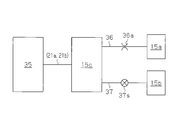
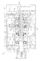
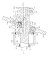
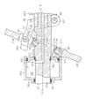
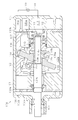
- a side sectional view showing a variable capacity type swash plate type compressor in an embodiment The schematic diagram which shows the relationship between a control pressure chamber, a pressure regulation chamber, a suction chamber, and a discharge chamber.
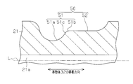
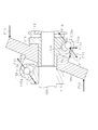
- the sectional side view which expands and shows a guide surface.
- the fragmentary sectional side view which shows a variable capacity type
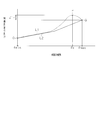
- the graph which shows the relationship between the pressure of a control pressure chamber, and the inclination-angle of a swash plate.
- Partial sectional side view of a variable capacity swash plate compressor showing the state when the inclination angle of the swash plate increases from the minimum inclination angle to a predetermined inclination angle and the dead volume of the first compression chamber becomes a predetermined size.
- Figure. The fragmentary sectional side view which shows the variable capacity
- the sectional side view which shows a variable capacity
- a variable capacity swash plate compressor (hereinafter simply referred to as “compressor”) is mounted on a vehicle.
- the housing 11 of the compressor 10 includes a first cylinder block 12 and a second cylinder block 13 joined to each other, and a front joined to the front (first side) first cylinder block 12.
- the housing 14 includes a rear housing 15 joined to the second cylinder block 13 on the rear side (second side).
- the first cylinder block 12 and the second cylinder block 13 are a pair of cylinder blocks that form the housing 11.
- a first valve / port forming body 16 is interposed between the front housing 14 and the first cylinder block 12.
- a second valve / port forming body 17 is interposed between the rear housing 15 and the second cylinder block 13.
- a suction chamber 14a and a discharge chamber 14b are defined between the front housing 14 and the first valve / port forming body 16.
- the discharge chamber 14b is disposed on the outer peripheral side of the suction chamber 14a.
- a suction chamber 15 a and a discharge chamber 15 b are defined between the rear housing 15 and the second valve / port forming body 17.
- the rear housing 15 is formed with a pressure adjusting chamber 15c.
- the pressure adjustment chamber 15c is located at the center of the rear housing 15, and the suction chamber 15a is disposed on the outer peripheral side of the pressure adjustment chamber 15c.
- the discharge chamber 15b is disposed on the outer peripheral side of the suction chamber 15a.
- the discharge chambers 14b and 15b are connected to each other via a discharge passage (not shown).
- the discharge passage is connected to an external refrigerant circuit (not shown).
- the first valve / port forming body 16 is formed with a suction port 16a communicating with the suction chamber 14a and a discharge port 16b communicating with the discharge chamber 14b.
- the second valve / port forming body 17 is formed with a suction port 17a communicating with the suction chamber 15a and a discharge port 17b communicating with the discharge chamber 15b.
- Each suction port 16a, 17a is provided with a suction valve mechanism (not shown), and each discharge port 16b, 17b is provided with a discharge valve mechanism (not shown).
- a rotating shaft 21 is rotatably supported in the housing 11.
- a portion on the front side (first side) of the rotating shaft 21 is inserted into a shaft hole 12 h penetrating the first cylinder block 12.
- the front portion of the rotating shaft 21 is located on the first side along the direction in which the central axis L of the rotating shaft 21 extends (the axial direction of the rotating shaft 21).
- the front end of the rotating shaft 21 is located in the front housing 14.
- the rear side (second side) portion of the rotating shaft 21 is inserted into a shaft hole 13 h penetrating the second cylinder block 13.
- the portion on the rear side of the rotating shaft 21 is a portion located on the second side along the direction in which the central axis L of the rotating shaft 21 extends.
- the rear end of the rotary shaft 21 is located in the pressure adjustment chamber 15c.
- the front part of the rotating shaft 21 is rotatably supported by the first cylinder block 12 through the shaft hole 12h.
- the rear part of the rotating shaft 21 is rotatably supported by the second cylinder block 13 through the shaft hole 13h.
- a lip seal type shaft seal device 22 is interposed between the front housing 14 and the rotary shaft 21.
- a crank chamber 24 defined by the first cylinder block 12 and the second cylinder block 13 is formed in the housing 11.
- the crank chamber 24 accommodates a swash plate 23 that rotates by obtaining a driving force from the rotating shaft 21 and that can tilt in the axial direction with respect to the rotating shaft 21.
- the swash plate 23 is formed with an insertion hole 23a through which the rotary shaft 21 can be inserted.
- the swash plate 23 is attached to the rotating shaft 21 by inserting the rotating shaft 21 into the insertion hole 23 a.
- the first cylinder block 12 has a plurality of first cylinder bores 12a (only one first cylinder bore 12a is shown in FIG. 1) as one cylinder bore penetrating in the axial direction of the first cylinder block 12 around the rotating shaft 21. It is arranged. Each first cylinder bore 12a communicates with the suction chamber 14a via the suction port 16a and also communicates with the discharge chamber 14b via the discharge port 16b.
- the second cylinder block 13 includes a plurality of second cylinder bores 13 a (only one second cylinder bore 13 a is shown in FIG. 1) around the rotation shaft 21 as the other cylinder bore penetrating in the axial direction of the second cylinder block 13. It is arranged.
- Each second cylinder bore 13a communicates with the suction chamber 15a via the suction port 17a and also communicates with the discharge chamber 15b via the discharge port 17b.
- the 1st cylinder bore 12a and the 2nd cylinder bore 13a are arranged so that it may become a pair in front and back.
- a double-headed piston 25 as a piston is accommodated so as to be able to reciprocate in the front-rear direction.
- Each double-headed piston 25 is moored to the outer peripheral portion of the swash plate 23 via a pair of shoes 26. Then, the rotational motion of the swash plate 23 accompanying the rotation of the rotating shaft 21 is converted into the reciprocating linear motion of the double-headed piston 25 via the shoe 26.
- a first compression chamber 20a is defined in each first cylinder bore 12a by a double-headed piston 25 and a first valve / port forming body 16.
- a second compression chamber 20b is defined by a double-headed piston 25 and a second valve / port forming body 17.
- the first cylinder block 12 is formed with a first large-diameter hole 12b that is continuous with the shaft hole 12h and has a larger diameter than the shaft hole 12h.
- the first large diameter hole 12 b communicates with the crank chamber 24.
- the crank chamber 24 and the suction chamber 14a communicate with each other through a suction passage 12c that passes through the first cylinder block 12 and the first valve / port forming body 16.
- the second cylinder block 13 is formed with a second large-diameter hole 13b that is continuous with the shaft hole 13h and has a larger diameter than the shaft hole 13h.
- the second large diameter hole 13 b communicates with the crank chamber 24.
- the crank chamber 24 and the suction chamber 15a communicate with each other through a suction passage 13c that passes through the second cylinder block 13 and the second valve / port forming body 17.
- a suction port 13 s is formed on the peripheral wall of the second cylinder block 13.
- the suction port 13s is connected to an external refrigerant circuit. Then, the refrigerant gas sucked into the crank chamber 24 from the external refrigerant circuit through the suction port 13s is sucked into the suction chambers 14a and 15a through the suction passages 12c and 13c. Accordingly, the suction chambers 14a and 15a and the crank chamber 24 are in a suction pressure region. The pressures in the suction chambers 14a and 15a and the crank chamber 24 are substantially equal.
- the rotary shaft 21 is provided with an annular flange portion 21f that is disposed in the first large-diameter hole 12b.
- a first thrust bearing 27 a is disposed between the flange portion 21 f and the first cylinder block 12 in the axial direction of the rotary shaft 21.
- a cylindrical support member 39 is press-fitted on the rear end side of the rotary shaft 21. From the outer peripheral surface of the support member 39, an annular flange portion 39f disposed in the second large-diameter hole 13b is projected.
- a second thrust bearing 27 b is disposed between the flange portion 39 f and the second cylinder block 13 in the axial direction of the rotary shaft 21.
- An annular partition body 31 that is provided on the rotary shaft 21 and that can rotate integrally with the rotary shaft 21 is fixed to the rear side of the flange portion 21 f of the rotary shaft 21 and to the front side of the swash plate 23. ing. Between the flange portion 21f and the partition body 31, a bottomed cylindrical moving body 32 that is movable in the axial direction of the rotary shaft 21 with respect to the partition body 31 is disposed.
- the moving body 32 is formed of an annular bottom portion 32a having an insertion hole 32e through which the rotating shaft 21 is inserted, and a cylindrical portion 32b extending along the axial direction of the rotating shaft 21 from the outer peripheral edge of the bottom portion 32a.
- the inner peripheral surface of the cylindrical portion 32 b is slidable with respect to the outer peripheral edge of the partition body 31.
- the moving body 32 can rotate integrally with the rotating shaft 21 via the partition body 31.
- the space between the inner peripheral surface of the cylindrical portion 32 b and the outer peripheral edge of the partition body 31 is sealed with a seal member 33, and the space between the insertion hole 32 e and the rotary shaft 21 is sealed with a seal member 34.
- a control pressure chamber 35 is partitioned between the partition body 31 and the moving body 32.
- the rotary shaft 21 is formed with a first in-axis passage 21 a extending along the axial direction of the rotary shaft 21.
- the rear end of the first in-axis passage 21a opens to the pressure adjustment chamber 15c.
- the rotation shaft 21 is formed with a second in-axis passage 21 b extending along the radial direction of the rotation shaft 21.
- One end of the second in-shaft passage 21 b communicates with the tip of the first in-shaft passage 21 a, and the other end opens to the control pressure chamber 35. Therefore, the control pressure chamber 35 and the pressure adjustment chamber 15c communicate with each other via the first in-axis passage 21a and the second in-axis passage 21b.
- the pressure adjusting chamber 15 c and the suction chamber 15 a communicate with each other through an extraction passage 36.
- the extraction passage 36 is provided with an orifice 36a, and the flow rate of the refrigerant gas flowing through the extraction passage 36 is restricted by the orifice 36a.
- the pressure adjusting chamber 15 c and the discharge chamber 15 b communicate with each other via the air supply passage 37.
- An electromagnetic control valve 37 s is provided on the air supply passage 37. The control valve 37s can adjust the opening degree of the air supply passage 37 based on the pressure of the suction chamber 15a. The flow rate of the refrigerant gas flowing through the air supply passage 37 is adjusted by the control valve 37s.
- Refrigerant gas is introduced from the discharge chamber 15b into the control pressure chamber 35 through the air supply passage 37, the pressure adjustment chamber 15c, the first in-shaft passage 21a, and the second in-shaft passage 21b.
- the refrigerant gas is discharged from the control pressure chamber 35 to the suction chamber 15a through the second shaft passage 21b, the first shaft passage 21a, the pressure adjustment chamber 15c, and the extraction passage 36.
- the refrigerant gas introduced into the control pressure chamber 35 is a control gas that adjusts the pressure of the control pressure chamber 35.
- the moving body 32 moves in the axial direction of the rotary shaft 21 with respect to the partition body 31 in accordance with the pressure difference between the control pressure chamber 35 and the crank chamber 24.
- a lug arm 40 is disposed between the swash plate 23 and the flange portion 39f.
- the lug arm 40 is formed in a substantially L shape from one end to the other end.
- a weight portion 40 a is formed at one end of the lug arm 40.
- the weight part 40 a passes through the groove part 23 b of the swash plate 23 and is located on the front side of the swash plate 23.
- the one end side of the lug arm 40 is connected to the upper end side (the upper side in FIG. 1) of the swash plate 23 by a first pin 41 crossing the inside of the groove 23b.
- one end side of the lug arm 40 is supported so as to be swingable around the first swing center M1 with respect to the swash plate 23 with the axis of the first pin 41 as the first swing center M1.
- the other end side of the lug arm 40 is connected to the support member 39 by the second pin 42.
- the other end side of the lug arm 40 is supported so as to be swingable around the second swing center M2 with respect to the support member 39 with the axis of the second pin 42 as the second swing center M2.
- Each connecting portion 32c is formed with a moving body insertion hole 32h through which a third pin 43 as a connecting member can be inserted.
- a swash plate insertion hole 23h through which the third pin 43 can be inserted is formed on the lower end side (lower side in FIG. 1) of the swash plate 23.
- the swash plate insertion hole 23 h has a long hole shape extending in the extending direction of the swash plate 23.
- the connecting portion 32 c is connected to the lower end side of the swash plate 23 by the third pin 43.
- the third pin 43 is restrained with respect to the connecting portion 32c by being press-fitted into the moving body insertion hole 32h, and is slidably held in the swash plate insertion hole 23h.
- the first connection position where the lug arm 40 and the swash plate 23 are connected by the first pin 41 is the rotation axis relative to the second connection position where the movable body 32 and the swash plate 23 are connected by the third pin 43. It is in the position which pinched 21.
- the swash plate 23 is provided with a fourth pin 44 as a sliding member so as to cross the inside of the insertion hole 23a.
- the fourth pin 44 is provided on the swash plate 23 so as to be disposed between the rotary shaft 21 and the first connection position where the lug arm 40 and the swash plate 23 are connected by the first pin 41.
- the fourth pin 44 is rotatably supported by the swash plate 23. Further, a part of the outer peripheral surface of the rotating shaft 21 (a portion facing the fourth pin 44) follows the change in the inclination angle of the swash plate 23, and the sliding portion 44a of the fourth pin 44 (the outer periphery of the fourth pin 44).
- a guide surface 50 is formed to be guided while sliding the surface).
- the guide surface 50 is formed by a groove recessed in the rotating shaft 21.
- the guide surface 50 includes an inclined portion 51 that is inclined with respect to the central axis L of the rotating shaft 21, and a flat portion 52 that is continuous with the inclined portion 51 and extends along the axial direction of the rotating shaft 21.
- the flat portion 52 is disposed on the rear side (side closer to the support member 39) than the inclined portion 51.
- the inclined portion 51 gradually increases such that the inclination angle with respect to the central axis L of the rotating shaft 21 gradually increases while moving away from the central axis L of the rotating shaft 21 from the position close to the moving body 32 toward the flat portion 52.
- Part 51a the inclined portion 51 has a gradually decreasing portion 51b in which the inclination angle with respect to the central axis L of the rotating shaft 21 gradually decreases while moving away from the central axis L of the rotating shaft 21 from the position close to the moving body 32 toward the flat portion 52.
- the gradually increasing portion 51 a includes a maximum inclined portion 51 c that is continuous with the gradually decreasing portion 51 b and has a maximum inclination angle with respect to the central axis L of the rotation shaft 21.
- the gradually increasing portion 51a, the maximum inclined portion 51c, and the gradually decreasing portion 51b are continuously provided from the position close to the moving body 32 toward the flat portion 52.
- the compressor 10 having the above-described configuration, when the valve opening degree of the control valve 37s is decreased, the discharge chamber 15b through the air supply passage 37, the pressure adjustment chamber 15c, the first in-shaft passage 21a, and the second in-shaft passage 21b. Thus, the flow rate of the refrigerant gas introduced into the control pressure chamber 35 is reduced. The refrigerant gas is discharged from the control pressure chamber 35 to the suction chamber 15a through the second in-shaft passage 21b, the first in-shaft passage 21a, the pressure adjustment chamber 15c, and the extraction passage 36, whereby the control pressure chamber 35 is discharged. Is substantially equal to the pressure in the suction chamber 15a. Therefore, when the pressure difference between the control pressure chamber 35 and the crank chamber 24 is reduced, the moving body 32 moves so that the bottom 32 a of the moving body 32 approaches the partition body 31.
- the lug arm 40 comes into contact with the flange portion 39f of the support member 39 when the inclination angle of the swash plate 23 reaches the minimum inclination angle ⁇ min.
- the inclination angle of the swash plate 23 is maintained at the minimum inclination angle ⁇ min.
- the discharge chamber 15b is connected to the control pressure chamber 35 via the air supply passage 37, the pressure adjustment chamber 15c, the first in-shaft passage 21a, and the second in-shaft passage 21b.
- the flow rate of the introduced refrigerant gas increases.
- the pressure in the control pressure chamber 35 becomes substantially equal to the pressure in the discharge chamber 15b. Therefore, when the pressure difference between the control pressure chamber 35 and the crank chamber 24 increases, the moving body 32 moves so that the bottom 32a of the moving body 32 is separated from the partition body 31.
- the third pin 43 slides inside the swash plate insertion hole 23h while applying a normal force to the swash plate 23, and the swash plate 23 swings around the first swing center M1 in the direction opposite to the swing direction when the tilt angle of the swash plate 23 is decreased.
- both ends of the lug arm 40 become the first swing center M1 and the first swing center M1, respectively.
- the moving body 32 comes into contact with the flange portion 21f when the inclination angle of the swash plate 23 reaches the maximum inclination angle ⁇ max.
- the lug arm 40, the first pin 41, and the second pin 42 constitute a link mechanism that allows the inclination angle of the swash plate 23 to be changed by the movement of the moving body 32.
- the swash plate 23 is supported by the rotary shaft 21 via the link mechanism, the moving body 32 and the fourth pin 44, and the inclination angle of the swash plate 23 with respect to the rotary shaft 21 is defined.
- a compression reaction force P ⁇ b> 1 acts on the swash plate 23 from the double-headed piston 25.
- the desired inclination angle is an inclination angle that is larger than the minimum inclination angle ⁇ min and smaller than the maximum inclination angle ⁇ max.
- the compression reaction force P1 acts on the swash plate 23 so as to reduce the inclination angle of the swash plate 23.
- a force F1 in the normal direction acts on the swash plate 23 at the contact portion between the third pin 43 and the swash plate 23.
- the force F1 extends toward the moving body 32 and intersects the moving direction of the moving body 32 (the axial direction of the rotating shaft 21).
- a force F 2 which is a reaction force of the force F 1 acting on the swash plate 23, acts on the connecting portion 32 c from the swash plate 23 via the third pin 43.
- the force F2 is decomposed into a force F2y having a component perpendicular to the moving direction of the moving body 32 (vertical direction) and a force F2x having a moving direction (horizontal) component of the moving body 32.
- a force F2y having a component in a direction orthogonal to the moving direction of the moving body 32 acts on the connecting portion 32c in a direction away from the rotating shaft 21.
- the force F2y having a component in a direction orthogonal to the moving direction of the moving body 32 acts on the moving body 32 so as to tilt the moving body 32 with respect to the moving direction via the connecting portion 32c.
- a force F3 extending toward the second swing center M2 is applied at the contact portion between the first pin 41 and the swash plate 23.
- a force F 4 which is a reaction force of the force F 3 acting on the swash plate 23, acts on the lug arm 40 from the swash plate 23 via the first pin 41.
- the sliding portion 44 a of the fourth pin 44 is guided by the flat portion 52 of the guide surface 50 of the rotating shaft 21, and the swash plate 23 passes through the sliding portion 44 a of the fourth pin 44.
- the rotary shaft 21 is supported. Therefore, the contact portion between the sliding portion 44a of the fourth pin 44 and the flat portion 52 of the guide surface 50 acts on the rotary shaft 21 from the swash plate 23 via the fourth pin 44 due to the balance of force.
- a force F6 which is a reaction force of the force F5 having a component in a direction perpendicular to the moving direction of the moving body 32, acts on the swash plate 23 from the rotating shaft 21 via the fourth pin 44.
- the inclination of the swash plate 23 is not changed by the compression reaction force P1 due to the balance between the forces F1 and F2, the balance between the forces F3 and F4, and the balance between the forces F5 and F6.
- the desired tilt angle is maintained.
- the force having a component in the direction perpendicular to the moving direction of the moving body 32 acting on the swash plate 23 is reduced.
- the force F2y having a component in the direction orthogonal to the moving direction of the moving body 32 acting on the connecting portion 32c from the swash plate 23 via the third pin 43 is reduced. Therefore, when the inclination angle of the swash plate 23 is changed, the moving body 32 is prevented from being inclined with respect to the moving direction, and the inclination angle of the swash plate 23 is changed smoothly.
- the inclination angle of the swash plate 23 decreases in the first compression chamber 20a.
- Dead volume increases.
- the dead volume is a clearance between the double-headed piston 25 at the top dead center position and the first valve / port forming body 16.
- the discharge stroke is performed without significantly increasing the dead volume.
- the suction pressure decreases in the suction stroke of the first compression chamber 20a.
- the re-expansion time is increased, and the force in the direction in which the inclination angle of the swash plate 23 acting on the swash plate 23 from the double-headed piston 25 decreases is increased.
- the tilt angle of the swash plate 23 decreases to a predetermined tilt angle ⁇ x and the dead volume of the first compression chamber 20a reaches a predetermined size
- the refrigerant gas is not discharged from the first compression chamber 20a. Therefore, in the process in which the inclination angle of the swash plate 23 decreases from the predetermined inclination angle ⁇ x to the minimum inclination angle ⁇ min, the first compression chamber 20a does not reach the discharge pressure, so that the discharge and intake of the refrigerant gas are not performed. Only the compression and expansion of the refrigerant gas are repeated. As a result, the force that presses the double-ended piston 25 due to the pressure in the first compression chamber 20a decreases, and the force in the direction in which the tilt angle acting on the swash plate 23 from the double-ended piston 25 decreases decreases.
- FIG. 6 the relationship between the pressure of the control pressure chamber 35 and the inclination angle of the swash plate 23 when the fourth pin 44 and the guide surface 50 are not provided (conventional) is indicated by a broken line L1.
- the swash plate 23 In the process in which the inclination angle of the swash plate 23 is changed between the minimum inclination angle ⁇ min and a predetermined inclination angle ⁇ x, the swash plate from the double-headed piston 25 to the swash plate 23 by re-expansion of the refrigerant gas in the first compression chamber 20a.
- the force acting in the direction in which the inclination angle of 23 decreases is relatively small. Therefore, as shown in FIG. 6, in order to increase the tilt angle of the swash plate 23 from the minimum tilt angle ⁇ min to the predetermined tilt angle ⁇ x, it is only necessary to increase the pressure in the control pressure chamber 35 (the point in the broken line L1). O to point P).
- the refrigerant gas in the first compression chamber 20a is when the inclination angle of the swash plate 23 is the predetermined inclination angle ⁇ x.
- the force acting in the direction in which the inclination angle of the swash plate 23 decreases with respect to the swash plate 23 from the double-headed piston 25 due to the re-expansion of the maximum is the largest.
- the double-headed piston 25 due to the compression reaction force P1 acting on the swash plate 23 from the double-headed piston 25 and the re-expansion of the refrigerant gas in the first compression chamber 20a.
- the resultant force with the force acting in the direction in which the inclination angle of the swash plate 23 decreases with respect to the swash plate 23 is the largest.
- the dead volume generated in the first compression chamber 20a decreases as the tilt angle of the swash plate 23 increases from the predetermined tilt angle ⁇ x to the maximum tilt angle ⁇ max, the refrigerant in the first compression chamber 20a decreases.
- the force acting in the direction in which the inclination angle of the swash plate 23 decreases with respect to the swash plate 23 from the double-headed piston 25 due to the re-expansion of gas decreases.
- the pressure in the control pressure chamber 35 for maintaining the tilt angle of the swash plate 23 becomes the largest when the tilt angle of the swash plate 23 is the predetermined tilt angle ⁇ x, and the tilt angle of the swash plate 23 is in the state of the predetermined tilt angle ⁇ x.
- the angle of inclination increases from 0 to the maximum inclination angle ⁇ max, it becomes smaller (the state from the point P to the point Q in the broken line L1).
- the pressure of the control pressure chamber 35 required to increase the tilt angle of the swash plate 23 from the predetermined tilt angle ⁇ x to the maximum tilt angle ⁇ max and the tilt angle of the swash plate 23 are increased from the minimum tilt angle ⁇ min to the predetermined tilt angle ⁇ x.
- the inclined portion 51 has a rotational axis as the sliding portion 44a of the fourth pin 44 moves in the moving direction when the inclination of the swash plate 23 in the moving body 32 decreases from the maximum inclination angle ⁇ max.
- 21 has a gradually increasing portion 51a in which an inclination angle with respect to the central axis L of 21 gradually increases.
- the shape of the inclined portion 51 is set so that the sliding portion 44a of the fourth pin 44 contacts the maximum inclined portion 51c when the inclination angle of the swash plate 23 is a predetermined inclination angle ⁇ x.
- the inclination angle of the swash plate 23 acting on the swash plate 23 from the double-headed piston 25 decreases.
- the inclination angle of the inclined portion 51 is adjusted so that the force on the inclination is received.
- the force in the direction in which the tilt angle of the swash plate 23 acting on the swash plate 23 from the double-headed piston 25 decreases is reduced. Therefore, as shown by the solid line L2 in FIG. 6, the inclination angle of the swash plate 23 is set to increase from the minimum inclination angle ⁇ min to the maximum inclination angle ⁇ max simply by increasing the pressure in the control pressure chamber 35.
- the force F8 acting on the swash plate 23 is decomposed into a force F8y having a component in a direction orthogonal to the moving direction of the moving body 32 and a force F8x having a component in the moving direction of the moving body 32. Therefore, a force F8x having a component in the moving direction of the moving body 32 acts on the swash plate 23 from the rotating shaft 21 via the fourth pin 44. A force F8x having a moving direction component of the moving body 32 acting on the swash plate 23 from the rotating shaft 21 via the fourth pin 44 is transferred to the moving body via the swash plate 23, the third pin 43, and the connecting portion 32c. 32.
- the force F8x having a component in the moving direction of the moving body 32 transmitted from the swash plate 23 to the moving body 32 assists the movement of the moving body 32 when the inclination angle of the swash plate 23 increases. Therefore, the moving body 32 can be moved even if the pressure in the control pressure chamber 35 is relatively small.
- the inclination angle of the swash plate 23 changes, so that the force acting on the swash plate 23 from the rotary shaft 21 via the fourth pin 44 according to the inclination angle of the swash plate 23.
- the direction of F8 changes, and the force F8y having a component in the direction orthogonal to the moving direction of the moving body 32 and the force F8x having a component in the moving direction of the moving body 32 are adjusted.
- the sliding portion 44a of the fourth pin 44 When the sliding portion 44a of the fourth pin 44 is in contact with the maximum inclined portion 51c, the sliding portion 44a of the fourth pin 44 is a portion other than the maximum inclined portion 51c in the gradually increasing portion 51a or the gradually decreasing portion 51b.
- the force F8x acting on the swash plate 23 is the largest compared to the case where it is in contact with. Therefore, the degree of assistance when the inclination of the swash plate 23 in the moving body 32 increases with the force F8x acting on the moving body 32 is as the inclination angle of the swash plate 23 increases from the minimum inclination angle ⁇ min to the predetermined inclination angle ⁇ x. It gradually increases and becomes the largest when the inclination angle of the swash plate 23 is a predetermined inclination angle ⁇ x.
- the degree of assistance in increasing the tilt angle of the swash plate 23 in the moving body 32 due to the force F8x acting on the moving body 32 is as the tilt angle of the swash plate 23 increases from the predetermined tilt angle ⁇ x to the maximum tilt angle ⁇ max. It gets smaller gradually.
- the conventional decrease degree of the pressure in the control pressure chamber 35 is from the state where the inclination angle of the swash plate 23 is the minimum inclination angle ⁇ min.
- the swash plate 23 is provided with a fourth pin 44 that slides on the rotary shaft 21. Further, a guide surface 50 for guiding the fourth pin 44 is provided on the rotary shaft 21.
- a compression reaction force P1 acts on the swash plate 23 from the double-ended piston 25
- a normal force F1 acts on the swash plate 23 at the contact portion between the third pin 43 and the swash plate 23.
- the inclination angle of the swash plate 23 is maintained at a desired inclination angle without being changed by the compression reaction force P1.
- a force F ⁇ b> 2 which is a reaction force of the normal-direction force F ⁇ b> 1 acting on 23, acts on the connecting portion 32 c of the moving body 32.
- the force F2 acting on the connecting portion 32c of the moving body 32 includes a force F2y having a component in a direction (vertical direction) orthogonal to the moving direction of the moving body 32 and a component in the moving direction (horizontal direction) of the moving body 32. It is decomposed into the force F2x it has.
- the force F2y having a component in a direction orthogonal to the moving direction of the moving body 32 acts on the connecting portion 32c of the moving body 32 in a direction away from the rotating shaft 21.
- the fourth pin 44 is guided by the guide surface 50 and the swash plate 23 is supported by the rotary shaft 21 via the fourth pin 44, so that the moving body 32 acting on the swash plate 23 moves in the moving direction.
- the force F2y having a component in the orthogonal direction is reduced.
- the force F2y having a component in a direction perpendicular to the moving direction of the moving body 32 acting on the connecting portion 32c of the moving body 32 via the third pin 43 from the swash plate 23 is reduced. Therefore, when the inclination angle of the swash plate 23 is changed, the moving body 32 is prevented from being inclined with respect to the moving direction, and the inclination angle of the swash plate 23 can be changed smoothly.
- the force F8 acting on the swash plate 23 is decomposed into a force F8y having a component in a direction orthogonal to the moving direction of the moving body 32 and a force F8x having a component in the moving direction of the moving body 32.
- the inclination angle of the swash plate 23 changes, so that the force acting on the swash plate 23 from the rotary shaft 21 via the fourth pin 44 according to the inclination angle of the swash plate 23.
- the direction of F8 can be changed, and the force F8y having a component in the direction orthogonal to the moving direction of the moving body 32 and the force F8x having a component in the moving direction of the moving body 32 can be adjusted.
- a force F8x having a component in the moving direction of the moving body 32 acts on the swash plate 23 from the rotating shaft 21 via the fourth pin 44, the connecting portion of the swash plate 23, the third pin 43, and the moving body 32. It is transmitted to the moving body 32 via 32c.
- the force F8x having a component in the moving direction of the moving body 32 transmitted from the swash plate 23 to the moving body 32 can be a force for assisting the movement of the moving body 32. If the movement of the moving body 32 is assisted by the force F8x having the moving direction component of the moving body 32 transmitted from the swash plate 23 to the moving body 32, the moving body even if the pressure of the control pressure chamber 35 is relatively small. 32 movements can be performed.
- the guide surface 50 has the inclined portion 51 that is guided so that the fourth pin 44 moves away from the central axis L of the rotating shaft 21 as the moving body 32 moves in a direction in which the inclination angle of the swash plate 23 decreases.
- the component in the moving direction of the moving body 32 acting on the swash plate 23 from the rotating shaft 21 via the fourth pin 44 is obtained.
- the force F8x is transmitted to the moving body 32 through the swash plate 23, the third pin 43, and the connecting portion 32c of the moving body 32, and the movement of the moving body 32 when the inclination angle of the swash plate 23 is increased is assisted. Thereby, the moving body 32 can be moved even if the pressure in the control pressure chamber 35 is relatively small.
- the force in the direction in which the tilt angle of the swash plate 23 acting on the swash plate 23 from the double-headed piston 25 decreases can be adjusted by the tilt angle of the guide surface 50.
- the force in the direction in which the tilt angle of the swash plate 23 acting on the swash plate 23 from the double-headed piston 25 decreases can be reduced.
- the inclination angle of the swash plate 23 can be set to increase from the minimum inclination angle ⁇ min to the maximum inclination angle ⁇ max only by increasing the pressure in the control pressure chamber 35.
- the third pin 43 is slidably held in the swash plate insertion hole 23h. According to this, when the inclination angle of the swash plate 23 is changed, the third pin 43 interferes with the swash plate 23 and the swash plate 23 tilts in the axial direction with respect to the rotation shaft 21. It is possible to prevent the situation from being lost.
- the swash plate 23 is provided with a fourth pin 44 having a sliding portion 44a. According to this, since the sliding portion 44a can be separated from the swash plate 23, the material of the sliding portion 44a is not limited to the material of the swash plate 23. Therefore, for example, the sliding resistance between the sliding part 44a and the rotating shaft 21 can be reduced by forming the fourth pin 44 with a material having excellent wear resistance.
- the fourth pin 44 is rotatably supported by the swash plate 23. According to this, compared with the case where the 4th pin 44 is supported by the swash plate 23 so that rotation is impossible, the sliding resistance between the 4th pin 44 and the rotating shaft 21 can be reduced.
- the first connection position where the lug arm 40 and the swash plate 23 are connected is a position sandwiching the rotary shaft 21 with respect to the second connection position where the movable body 32 and the swash plate 23 are connected.
- the fourth pin 44 is provided on the swash plate 23 so as to be disposed between the first coupling position and the rotating shaft 21.
- the compressor 10 having such a configuration is preferable in terms of ease of manufacturing.
- the inclined portion 51 is a gradually decreasing portion in which the inclination angle of the rotation shaft 21 with respect to the central axis L gradually decreases as the fourth pin 44 moves in the moving direction when the inclination angle of the swash plate 23 in the moving body 32 decreases. 51b.
- the gradually increasing portion 51a has a maximum inclined portion 51c that is continuous with the gradually decreasing portion 51b and has a maximum inclination angle with respect to the central axis L of the rotating shaft 21.
- the force F8x acting on the swash plate 23 is the largest compared to the case where the Therefore, the degree of assistance when the inclination of the swash plate 23 in the moving body 32 increases with the force F8x acting on the moving body 32 is as the inclination angle of the swash plate 23 increases from the minimum inclination angle ⁇ min to the predetermined inclination angle ⁇ x. It gradually increases and becomes the largest when the inclination angle of the swash plate 23 is a predetermined inclination angle ⁇ x.
- the degree of assistance in increasing the tilt angle of the swash plate 23 in the moving body 32 due to the force F8x acting on the moving body 32 is as the tilt angle of the swash plate 23 increases from the predetermined tilt angle ⁇ x to the maximum tilt angle ⁇ max. It gets smaller gradually. As a result, it is possible to increase the tilt angle of the swash plate 23 simply by increasing the pressure of the control pressure chamber 35 monotonously, and further adjusting the pressure of the control pressure chamber 35 when changing the tilt angle of the swash plate 23. It can be easy.
- the partition body 31 may not be fixed to the rotation shaft 21, and the partition body 31 may be movable in the axial direction of the rotation shaft 21 with respect to the rotation shaft 21.
- a seal member 61 is disposed between the inner peripheral surface of the partition body 31 and the rotary shaft 21, and the space between the inner peripheral surface of the partition body 31 and the rotary shaft 21 is sealed by the seal member 61.
- an annular step portion 21 g is formed between the opening facing the control pressure chamber 35 in the second in-axis passage 21 b and the swash plate 23.
- the division body 31 is contact
- An annular circlip 62 is mounted on the outer peripheral surface of the rotating shaft 21 between the opening facing the control pressure chamber 35 in the second in-axis passage 21b and the step portion 21g.
- the division body 31 is contact
- a protrusion 63 is formed on the end face of the swash plate 23 on the partition 31 side.
- the protrusion 63 comes into contact with the partition body 31 when the inclination angle of the swash plate 23 reaches the maximum inclination angle ⁇ max.
- the inclination angle of the swash plate 23 is maintained at the maximum inclination angle ⁇ max.
- the projection 63 contacts the partition body 31 the partition body 31 moves toward the circlip 62. Due to the movement of the partition body 31 toward the circlip 62, the impact when the projection 63 abuts on the partition body 31 is reduced.
- the partition body 31 moved toward the circlip 62 moves until it contacts the stepped portion 21g while maintaining the state where the projection 63 and the partition body 31 are in contact with each other by the pressure in the control pressure chamber 35. To do. Thereby, the inclination angle of the swash plate 23 becomes the maximum inclination angle ⁇ max.
- the circlip is made to follow the moving body 32 as the moving body 32 moves. Move towards 62. According to this, the frictional resistance between the inner peripheral surface of the cylindrical portion 32 b of the movable body 32 and the outer peripheral edge of the partition body 31 is reduced as compared with the case where the partition body 31 is fixed to the rotating shaft 21. Is done. Therefore, the inclination angle of the swash plate 23 can be changed smoothly.
- the housing 71 of the compressor 70 includes a cylinder block 72, a front housing 74 joined to the front end of the cylinder block 72, and a rear housing 15 joined to the rear end of the cylinder block 72. It is configured.
- a crank chamber 75 defined by a cylinder block 72 and a front housing 74 is formed in the housing 71.
- a plurality of cylinder bores 72 a (only one cylinder bore 72 a is shown in FIG. 8) penetrating in the axial direction of the cylinder block 72 are arranged around the rotary shaft 21.
- Each cylinder bore 72a communicates with the suction chamber 15a via the suction port 17a and also communicates with the discharge chamber 15b via the discharge port 17b.
- a single-head piston 76 as a piston is accommodated so as to be able to reciprocate in the front-rear direction.
- the configuration of the compressor 70 can be simplified and the size of the rotary shaft 21 can be reduced.
- a force having a component in the moving direction of the moving body 32 transmitted from the swash plate 23 to the moving body 32 may be a force that prevents the moving body 32 from moving. If the movement of the moving body 32 is hindered by the force having the component in the moving direction of the moving body 32 transmitted from the swash plate 23 to the moving body 32, the moving body must be set to a relatively high pressure unless the pressure in the control pressure chamber 35 is relatively large. 32 cannot be moved. Thus, the pressure in the control pressure chamber 35 can be adjusted by the force having the component in the moving direction of the moving body 32 transmitted from the swash plate 23 to the moving body 32.
- the moving body insertion hole 32 h may have a long hole shape extending in the extending direction of the swash plate 23.
- the third pin 43 is constrained to the swash plate 23 by being press-fitted into the swash plate insertion hole 23h, and is slidable in the extending direction of the swash plate 23 inside the movable body insertion hole 32h. It may be.
- the swash plate 23 may be integrally formed with a sliding portion that slides on the rotating shaft 21.
- the fourth pin 44 may be provided so as not to rotate with respect to the swash plate 23.
- a first connection position where the lug arm 40 and the swash plate 23 are connected
- a second connection position where the movable body 32 and the swash plate 23 are connected
- a sliding portion 44a provided on the swash plate 23
- the arrangement position is not particularly limited.
- the guide surface 50 may be formed over the entire outer peripheral surface of the rotating shaft 21. According to this, compared with the case where the guide surface 50 is formed on a part of the outer peripheral surface of the rotary shaft 21, the processing when the guide surface 50 is formed on the rotary shaft 21 is easier.
- the inclined portion 51 is formed with the gradually increasing portion 51a, the maximum inclined portion 51c, and the gradually decreasing portion 51b, but the inclined portion 51 may have a constant inclination angle with respect to the central axis L.
- the guide surface 50 may be formed by appropriately combining the inclined portion 51 and the flat portion 52. In the embodiment, the guide surface 50 does not have the inclined portion 51 and may be formed only by the flat portion 52 extending along the axial direction of the rotation shaft 21.
- the guide surface 50 does not have the flat portion 52 and may be formed only by the inclined portion 51. Moreover, the inclination direction of the inclination part 51 is not specifically limited. In the embodiment, the outer peripheral surface of the rotating shaft 21 may function as a guide surface without forming a groove in the rotating shaft 21.
- Lug arm constituting link mechanism 41 ... Link mechanism First pin constituting 42, second pin constituting the link mechanism, 43 third pin as a connecting member, 44 fourth pin as a sliding member , 44a ... sliding portion, 50 ... guide surface, 51 ... inclined portion 72 ... cylinder block, 72a ... cylinder bores, 76 ... single-headed piston as a piston.
Landscapes
- Engineering & Computer Science (AREA)
- Mechanical Engineering (AREA)
- General Engineering & Computer Science (AREA)
- Compressors, Vaccum Pumps And Other Relevant Systems (AREA)
Abstract
Description
摺動部と案内面との接触部においては、斜板から摺動部を介して案内面に法線方向の力が作用する。そして、案内面と摺動部との接触部においては、力の釣り合いの関係により、案内面に作用する法線方向の力の反力である力が、回転軸から摺動部を介して斜板に作用する。この斜板に作用する力は、移動体の移動方向に直交する方向の成分を有する力と、移動体の移動方向の成分を有する力とに分解される。よって、斜板の傾角変更に伴い、案内面の傾斜角度が変化することにより、斜板の傾角に応じて、回転軸から摺動部を介して斜板に作用する力の向きを変化させることができ、移動体の移動方向に直交する方向の成分を有する力と、移動体の移動方向の成分を有する力とを調整することができる。
これによれば、摺動部を、斜板とは別体とすることができるため、摺動部の材質が斜板の材質に制限されることがない。よって、例えば、摺動部材を耐摩耗性の優れた材料で形成することで、摺動部と回転軸との間の摺動抵抗を低減することができる。
これによれば、摺動部材が斜板に回転不能に支持されている場合に比べると、摺動部材と回転軸との間の摺動抵抗を低減することができる。
図1に示すように、圧縮機10のハウジング11は、互いに接合された第1シリンダブロック12及び第2シリンダブロック13と、前方側(第1側)の第1シリンダブロック12に接合されたフロントハウジング14と、後方側(第2側)の第2シリンダブロック13に接合されたリヤハウジング15とから構成されている。第1シリンダブロック12及び第2シリンダブロック13は、ハウジング11を形成する一対のシリンダブロックである。
図5に示すように、例えば、圧縮機10が、斜板23の傾角が所望の傾角で運転している場合、両頭ピストン25から斜板23に対して圧縮反力P1が作用する。なお、所望の傾角は、図5では最小傾角θminよりも大きく最大傾角θmaxよりも小さい傾角である。この圧縮反力P1は、斜板23の傾角を減少させるように斜板23に対して作用する。
(1)斜板23に、回転軸21に摺動する第4ピン44を設けた。さらに、回転軸21に、第4ピン44を案内する案内面50を設けた。両頭ピストン25から斜板23に対して圧縮反力P1が作用すると、第3ピン43と斜板23との接触部において、斜板23に法線方向の力F1が作用する。そして、第3ピン43と移動体32の連結部32cとの接触部においては、斜板23の傾角が、圧縮反力P1により変更されること無く所望の傾角に維持されるために、斜板23に作用する法線方向の力F1の反力である力F2が移動体32の連結部32cに作用する。この移動体32の連結部32cに作用する力F2は、移動体32の移動方向に直交する方向(垂直方向)の成分を有する力F2yと、移動体32の移動方向(水平方向)の成分を有する力F2xとに分解される。この移動体32の移動方向に直交する方向の成分を有する力F2yは、回転軸21から離間する方向に向けて移動体32の連結部32cに作用する。
このとき、第4ピン44が案内面50に案内されて、斜板23が第4ピン44を介して回転軸21に支持されることで、斜板23に作用する移動体32の移動方向に直交する方向の成分を有する力F2yが低減される。このため、斜板23から第3ピン43を介して移動体32の連結部32cに作用する移動体32の移動方向に直交する方向の成分を有する力F2yが低減される。よって、斜板23の傾角を変更する際に、移動体32が移動方向に対して傾いてしまうことが抑制され、斜板23の傾角の変更をスムーズに行うことができる。
○ 図8に示すように、区画体31が回転軸21に固定されていなくてもよく、区画体31が回転軸21に対して回転軸21の軸方向に移動可能であってもよい。区画体31の内周面と回転軸21との間にはシール部材61が配設されており、区画体31の内周面と回転軸21との間がシール部材61によりシールされている。回転軸21の外周面において、第2軸内通路21bにおける制御圧室35に臨む開口と斜板23との間には、円環状の段差部21gが形成されている。そして、区画体31は、段差部21gに当接することで、回転軸21の軸方向における斜板23側への移動が規制される。また、回転軸21の外周面において、第2軸内通路21bにおける制御圧室35に臨む開口と段差部21gとの間には、円環状のサークリップ62が装着されている。そして、区画体31は、サークリップ62に当接することで、回転軸21の軸方向における斜板23とは反対側への移動が規制される。よって、区画体31は、第2軸内通路21bにおける制御圧室35に臨む開口を乗り越えた位置まで移動することが規制されている。区画体31は、回転軸21の回転力がシール部材61を介して伝達されることにより回転する。
○ 実施形態において、第4ピン44が斜板23に対して回転不能に設けられていてもよい。
○ 実施形態において、案内面50が傾斜部51を有しておらず、回転軸21の軸方向に沿って延びる平坦部52のみで形成されていてもよい。
○ 実施形態において、回転軸21に溝を凹設せずに、回転軸21の外周面を案内面として機能させてもよい。
Claims (8)
- ハウジングを形成するシリンダブロックには複数のシリンダボアが形成されており、各シリンダボア内にはピストンが往復動可能にそれぞれ収容され、クランク室には、回転軸に固定されるとともに該回転軸と一体回転するリンク機構と、該リンク機構を介して前記回転軸からの駆動力を得て回転するとともに前記回転軸に対する傾角が変更される斜板とが収容されており、前記斜板に前記ピストンが係留されている可変容量型斜板式圧縮機であって、
前記回転軸上に設けられた区画体と、
連結部材を介して前記斜板に連結されて、前記区画体に対して前記回転軸の軸方向に移動して、前記斜板の傾角を変更可能な移動体と、
前記移動体と前記区画体とにより区画されて、制御ガスが導入されて内部の圧力が変更されることで該移動体を移動させる制御圧室と、
前記斜板に設けられ、前記回転軸に摺動する摺動部と、
前記回転軸に設けられ、前記摺動部を案内する案内面とを備え、
前記斜板は、前記リンク機構、前記移動体及び前記摺動部を介して前記回転軸に支持されて、前記斜板の前記回転軸に対する傾角が規定される可変容量型斜板式圧縮機。 - 前記斜板の傾角変更に伴い、前記回転軸の中心軸線に対する前記案内面の傾斜角度が変化する請求項1に記載の可変容量型斜板式圧縮機。
- 前記案内面は、前記斜板の傾角が減少する方向に前記移動体が移動するにつれて、前記摺動部が前記中心軸線から離間するように案内される傾斜部を有する請求項2に記載の可変容量型斜板式圧縮機。
- 前記ハウジングは一対のシリンダブロックを有しており、
各シリンダブロックにそれぞれ形成された対となるシリンダボアに前記ピストンとしての両頭ピストンが往復動可能に収容されており、
前記両頭ピストンによって、一方のシリンダボア内に第1圧縮室が区画されるとともに、他方のシリンダボア内に第2圧縮室が区画されている請求項2又は請求項3に記載の可変容量型斜板式圧縮機。 - 前記連結部材は、前記移動体に設けられた移動側挿通孔と、前記斜板に設けられた斜板挿通孔とに挿通されるとともに、前記移動側挿通孔、又は前記斜板挿通孔のいずれか一方にスライド移動可能に保持されている請求項1~請求項4のいずれか一項に記載の可変容量型斜板式圧縮機。
- 前記斜板には、前記摺動部を有する摺動部材が設けられている請求項1~請求項5のいずれか一項に記載の可変容量型斜板式圧縮機。
- 前記摺動部材は、前記斜板に回転可能に支持されている請求項6に記載の可変容量型斜板式圧縮機。
- 前記リンク機構は、前記斜板に連結されるとともに前記回転軸に固定されて該回転軸と一体回転するラグアームを有し、
前記ラグアームと前記斜板とが連結される第1連結位置は、前記移動体と前記斜板とが連結される第2連結位置に対して前記回転軸を挟んだ位置であり、
前記摺動部は、前記第1連結位置と前記回転軸との間に配置されるように前記斜板に設けられている請求項1~請求項7のいずれか一項に記載の可変容量型斜板式圧縮機。
Priority Applications (5)
| Application Number | Priority Date | Filing Date | Title |
|---|---|---|---|
| US14/779,588 US9624919B2 (en) | 2013-03-29 | 2014-03-28 | Variable displacement swash plate type compressor |
| JP2015508748A JP5983863B2 (ja) | 2013-03-29 | 2014-03-28 | 可変容量型斜板式圧縮機 |
| CN201480016590.5A CN105190031B (zh) | 2013-03-29 | 2014-03-28 | 可变容量型斜板式压缩机 |
| KR1020157026336A KR101777183B1 (ko) | 2013-03-29 | 2014-03-28 | 가변 용량형 사판식 압축기 |
| DE112014001762.0T DE112014001762T5 (de) | 2013-03-29 | 2014-03-28 | Taumelscheibenkompressor mit variabler Kapazität |
Applications Claiming Priority (2)
| Application Number | Priority Date | Filing Date | Title |
|---|---|---|---|
| JP2013-073818 | 2013-03-29 | ||
| JP2013073818 | 2013-03-29 |
Publications (1)
| Publication Number | Publication Date |
|---|---|
| WO2014157604A1 true WO2014157604A1 (ja) | 2014-10-02 |
Family
ID=51624560
Family Applications (1)
| Application Number | Title | Priority Date | Filing Date |
|---|---|---|---|
| PCT/JP2014/059080 Ceased WO2014157604A1 (ja) | 2013-03-29 | 2014-03-28 | 可変容量型斜板式圧縮機 |
Country Status (6)
| Country | Link |
|---|---|
| US (1) | US9624919B2 (ja) |
| JP (1) | JP5983863B2 (ja) |
| KR (1) | KR101777183B1 (ja) |
| CN (1) | CN105190031B (ja) |
| DE (1) | DE112014001762T5 (ja) |
| WO (1) | WO2014157604A1 (ja) |
Families Citing this family (4)
| Publication number | Priority date | Publication date | Assignee | Title |
|---|---|---|---|---|
| US20160069334A1 (en) * | 2013-03-29 | 2016-03-10 | Kabushiki Kaisha Toyota Jidoshokki | Variable displacement swash plate type compressor |
| JP6264105B2 (ja) * | 2014-03-10 | 2018-01-24 | 株式会社豊田自動織機 | 可変容量型斜板式圧縮機 |
| JP2016102434A (ja) * | 2014-11-27 | 2016-06-02 | 株式会社豊田自動織機 | 可変容量型斜板式圧縮機 |
| JP2016151188A (ja) * | 2015-02-16 | 2016-08-22 | 株式会社豊田自動織機 | 容量可変型斜板式圧縮機 |
Citations (3)
| Publication number | Priority date | Publication date | Assignee | Title |
|---|---|---|---|---|
| JPH0311168A (ja) * | 1989-06-07 | 1991-01-18 | Toyota Autom Loom Works Ltd | 斜板式可変容量圧縮機 |
| JPH05172052A (ja) * | 1991-12-18 | 1993-07-09 | Sanden Corp | 可変容量斜板式圧縮機 |
| JPH0658108B2 (ja) * | 1985-10-21 | 1994-08-03 | 株式会社日立製作所 | アキシヤル・ピストン・コンプレツサ |
Family Cites Families (9)
| Publication number | Priority date | Publication date | Assignee | Title |
|---|---|---|---|---|
| US4061443A (en) * | 1976-12-02 | 1977-12-06 | General Motors Corporation | Variable stroke compressor |
| US4108577A (en) * | 1977-06-09 | 1978-08-22 | General Motors Corporation | Variable displacement compressor |
| US4174191A (en) * | 1978-01-18 | 1979-11-13 | Borg-Warner Corporation | Variable capacity compressor |
| JPS58162781A (ja) * | 1982-03-20 | 1983-09-27 | Toyoda Autom Loom Works Ltd | 可変容量型斜板圧縮機の斜板傾斜角度制御装置 |
| JP2600305B2 (ja) | 1988-07-05 | 1997-04-16 | 株式会社豊田自動織機製作所 | 可変容量型斜板式圧縮機 |
| JPH0518355A (ja) * | 1991-07-15 | 1993-01-26 | Toyota Autom Loom Works Ltd | 可変容量型圧縮機 |
| JP2009068358A (ja) * | 2007-09-11 | 2009-04-02 | Toyota Industries Corp | 容量可変型斜板式圧縮機 |
| JP6003546B2 (ja) * | 2012-11-05 | 2016-10-05 | 株式会社豊田自動織機 | 容量可変型斜板式圧縮機 |
| JP6171875B2 (ja) * | 2013-11-13 | 2017-08-02 | 株式会社豊田自動織機 | 可変容量型斜板式圧縮機 |
-
2014
- 2014-03-28 WO PCT/JP2014/059080 patent/WO2014157604A1/ja not_active Ceased
- 2014-03-28 US US14/779,588 patent/US9624919B2/en not_active Expired - Fee Related
- 2014-03-28 DE DE112014001762.0T patent/DE112014001762T5/de not_active Withdrawn
- 2014-03-28 CN CN201480016590.5A patent/CN105190031B/zh not_active Expired - Fee Related
- 2014-03-28 JP JP2015508748A patent/JP5983863B2/ja not_active Expired - Fee Related
- 2014-03-28 KR KR1020157026336A patent/KR101777183B1/ko not_active Expired - Fee Related
Patent Citations (3)
| Publication number | Priority date | Publication date | Assignee | Title |
|---|---|---|---|---|
| JPH0658108B2 (ja) * | 1985-10-21 | 1994-08-03 | 株式会社日立製作所 | アキシヤル・ピストン・コンプレツサ |
| JPH0311168A (ja) * | 1989-06-07 | 1991-01-18 | Toyota Autom Loom Works Ltd | 斜板式可変容量圧縮機 |
| JPH05172052A (ja) * | 1991-12-18 | 1993-07-09 | Sanden Corp | 可変容量斜板式圧縮機 |
Also Published As
| Publication number | Publication date |
|---|---|
| KR101777183B1 (ko) | 2017-09-11 |
| DE112014001762T5 (de) | 2015-12-17 |
| CN105190031A (zh) | 2015-12-23 |
| CN105190031B (zh) | 2017-03-15 |
| US20160047366A1 (en) | 2016-02-18 |
| KR20150121172A (ko) | 2015-10-28 |
| US9624919B2 (en) | 2017-04-18 |
| JP5983863B2 (ja) | 2016-09-06 |
| JPWO2014157604A1 (ja) | 2017-02-16 |
Similar Documents
| Publication | Publication Date | Title |
|---|---|---|
| KR101562629B1 (ko) | 용량 가변형 사판식 압축기 | |
| JP6115258B2 (ja) | 両頭ピストン型斜板式圧縮機 | |
| JP5983863B2 (ja) | 可変容量型斜板式圧縮機 | |
| KR101781714B1 (ko) | 가변 용량형 사판식 압축기 | |
| JP6079379B2 (ja) | 可変容量型斜板式圧縮機 | |
| JP6171875B2 (ja) | 可変容量型斜板式圧縮機 | |
| JP6194837B2 (ja) | 容量可変型斜板式圧縮機 | |
| JP5983657B2 (ja) | 容量可変型斜板式圧縮機 | |
| JP6032146B2 (ja) | 両頭ピストン型斜板式圧縮機 | |
| CN105889017B (zh) | 可变排量旋转斜板式压缩机 | |
| WO2014156799A1 (ja) | 容量可変型斜板式圧縮機 | |
| JP6179439B2 (ja) | 容量可変型斜板式圧縮機 | |
| WO2014157208A1 (ja) | 容量可変型斜板式圧縮機 | |
| JP5949805B2 (ja) | 容量可変型斜板式圧縮機 | |
| JP6115397B2 (ja) | 容量可変型斜板式圧縮機 | |
| JP2015175350A (ja) | 可変容量型斜板式圧縮機 | |
| JP2017180239A (ja) | 容量可変型斜板式圧縮機 | |
| JP2016160891A (ja) | 可変容量型斜板式圧縮機 | |
| JP2016121667A (ja) | 可変容量型斜板式圧縮機 | |
| JP2016156335A (ja) | 斜板式圧縮機 | |
| JP2015169174A (ja) | 可変容量型斜板式圧縮機 |
Legal Events
| Date | Code | Title | Description |
|---|---|---|---|
| WWE | Wipo information: entry into national phase |
Ref document number: 201480016590.5 Country of ref document: CN |
|
| 121 | Ep: the epo has been informed by wipo that ep was designated in this application |
Ref document number: 14774612 Country of ref document: EP Kind code of ref document: A1 |
|
| ENP | Entry into the national phase |
Ref document number: 2015508748 Country of ref document: JP Kind code of ref document: A |
|
| ENP | Entry into the national phase |
Ref document number: 20157026336 Country of ref document: KR Kind code of ref document: A |
|
| WWE | Wipo information: entry into national phase |
Ref document number: 14779588 Country of ref document: US |
|
| WWE | Wipo information: entry into national phase |
Ref document number: 112014001762 Country of ref document: DE Ref document number: 1120140017620 Country of ref document: DE |
|
| 122 | Ep: pct application non-entry in european phase |
Ref document number: 14774612 Country of ref document: EP Kind code of ref document: A1 |