WO2014157263A1 - 有機汚泥の脱水方法および脱水設備 - Google Patents
有機汚泥の脱水方法および脱水設備 Download PDFInfo
- Publication number
- WO2014157263A1 WO2014157263A1 PCT/JP2014/058394 JP2014058394W WO2014157263A1 WO 2014157263 A1 WO2014157263 A1 WO 2014157263A1 JP 2014058394 W JP2014058394 W JP 2014058394W WO 2014157263 A1 WO2014157263 A1 WO 2014157263A1
- Authority
- WO
- WIPO (PCT)
- Prior art keywords
- organic
- organic sludge
- sludge
- organic solvent
- dewatering
- Prior art date
- Legal status (The legal status is an assumption and is not a legal conclusion. Google has not performed a legal analysis and makes no representation as to the accuracy of the status listed.)
- Ceased
Links
Images







Classifications
-
- C—CHEMISTRY; METALLURGY
- C02—TREATMENT OF WATER, WASTE WATER, SEWAGE, OR SLUDGE
- C02F—TREATMENT OF WATER, WASTE WATER, SEWAGE, OR SLUDGE
- C02F11/00—Treatment of sludge; Devices therefor
- C02F11/12—Treatment of sludge; Devices therefor by de-watering, drying or thickening
- C02F11/14—Treatment of sludge; Devices therefor by de-watering, drying or thickening with addition of chemical agents
- C02F11/147—Treatment of sludge; Devices therefor by de-watering, drying or thickening with addition of chemical agents using organic substances
-
- C—CHEMISTRY; METALLURGY
- C02—TREATMENT OF WATER, WASTE WATER, SEWAGE, OR SLUDGE
- C02F—TREATMENT OF WATER, WASTE WATER, SEWAGE, OR SLUDGE
- C02F11/00—Treatment of sludge; Devices therefor
- C02F11/12—Treatment of sludge; Devices therefor by de-watering, drying or thickening
- C02F11/121—Treatment of sludge; Devices therefor by de-watering, drying or thickening by mechanical de-watering
- C02F11/122—Treatment of sludge; Devices therefor by de-watering, drying or thickening by mechanical de-watering using filter presses
-
- C—CHEMISTRY; METALLURGY
- C02—TREATMENT OF WATER, WASTE WATER, SEWAGE, OR SLUDGE
- C02F—TREATMENT OF WATER, WASTE WATER, SEWAGE, OR SLUDGE
- C02F2103/00—Nature of the water, waste water, sewage or sludge to be treated
- C02F2103/32—Nature of the water, waste water, sewage or sludge to be treated from the food or foodstuff industry, e.g. brewery waste waters
Definitions
- the present invention relates to a dewatering method and dewatering equipment for organic sludge containing organic substances generated from, for example, sewage and the food industry.
- dimethyl ether which is a gas at normal temperature and pressure
- this organic sludge is placed in the pressure vessel 101.
- the pressure in the pressurized container 101 is released and returned to normal temperature and normal pressure, thereby vaporizing dimethyl ether and recovering the vaporized dimethyl ether, as shown in FIG. 16 (c).
- organic sludge and water are taken out from the pressurized container 101 and solid-liquid separated by the solid-liquid separator 102.
- water in the cell membrane included water
- the dehydration method as described above is described in, for example, Patent Document 1 below.
- An object of the present invention is to provide a dewatering method and dewatering equipment for organic sludge that can easily reduce the moisture content of the organic sludge without using a pressure vessel.
- the first invention is a method for dewatering organic sludge containing an organic substance having a cell membrane, Perform a mixing process that mixes organic solvent that is liquid and volatile under normal temperature and pressure with organic sludge, The organic sludge mixed with the organic solvent is supplied to the dehydrator of the dehydrator equipped with a heating means to perform the dehydration process, In the dehydration step, the organic sludge in the dehydration part is heated to a first predetermined temperature equal to or higher than the boiling point of the organic solvent to vaporize the organic solvent mixed in the organic sludge, The vaporized organic solvent is discharged from the dehydration unit and collected.
- the cell membrane of organic matter in organic sludge is dissolved and damaged by the organic solvent, it becomes possible to dehydrate the contained water using a dehydrator, and the water content of the organic sludge can be easily reduced. it can. Moreover, since the viscosity of a liquid falls by heating, the dehydration rate and desolvation rate of organic sludge become high. Furthermore, since the organic solvent is a liquid at normal temperature and normal pressure, there is no need to pressurize the organic sludge mixed with the organic solvent in the pressure vessel, and troublesome safety management relating to the first type pressure vessel is not required.
- the organic solvent has a boiling point lower than that of water
- the first predetermined temperature is higher than the boiling point of the organic solvent and lower than the boiling point of water.
- the organic sludge dewatering method starts supplying the organic sludge to the dewatering unit in a state where the dewatering unit is at a second predetermined temperature lower than the boiling point of the organic solvent. After the start of supply, the organic sludge in the dewatering unit is heated to the first predetermined temperature. According to this, when the supply of organic sludge to the dewatering part of the dehydrator is started, the dehydration part is at the second predetermined temperature, and therefore the organic solvent mixed with the organic sludge when the supply of organic sludge is started. Can be prevented from bumping.
- the method for dewatering organic sludge according to the fourth aspect of the invention is to collect the vaporized organic solvent by sucking it out from the dewatering section and returning it from gas to liquid. According to this, since the organic solvent is recovered by returning from the gas to the liquid, the recovered organic solvent in the liquid can be repeatedly reused as it is.
- the organic sludge dewatering method dissolves the crude fat constituting the organic cell membrane in the mixing step, In the dehydration step, the filtrate in which the crude fat constituting the cell membrane is dissolved is discharged. According to this, since the crude fat constituting the cell membrane of the organic matter in the organic sludge is dissolved by the organic solvent and the cell membrane is damaged, it becomes possible to dehydrate the contained water using a dehydrator, and the water content of the organic sludge The rate can be easily reduced. At this time, since the organic solvent is a liquid at normal temperature and normal pressure, it is not necessary to pressurize the organic sludge mixed with the organic solvent in the pressure vessel, and troublesome safety management relating to the first type pressure vessel is not required.
- the organic sludge dewatering method sets the mixing ratio of the organic solvent using as an index the transfer rate at which the crude fat generated by dissolution of the cell membrane moves from the organic sludge to the filtrate. According to this, it is possible to dehydrate organic sludge using an appropriate amount of organic solvent by setting the mixing ratio of organic solvent using the migration rate of crude fat as an index, and excess organic solvent. Mixing and wasting can be prevented. Furthermore, since the dehydration efficiency can be improved without excessively increasing the BOD (biochemical oxygen demand) of the filtrate, the load when processing the filtrate is reduced.
- BOD biological oxygen demand
- the organic sludge dehydration method sets the mixing ratio of the organic solvent so that the migration rate of the crude fat falls within a predetermined range of 4% by weight to 60% by weight.
- the relationship in which the moisture content of the organic sludge after the dehydration step decreases as the migration rate of the crude fat increases is maintained. Therefore, in the predetermined range of 4 wt% or more to 60 wt% or less, increasing the mixing ratio of the organic solvent increases the rate of transfer of crude fat from the organic sludge to the filtrate, and the organic sludge after the dehydration step. The moisture content of is reduced. Therefore, by setting the migration rate within the predetermined range of 4% by weight to 60% by weight, it is possible to dehydrate the organic sludge using an appropriate amount of the organic solvent, and the organic solvent is mixed excessively. Can be avoided.
- the migration rate is less than 4% by weight, even if the mixing ratio of the organic solvent is increased, there is no change in the moisture content of the organic sludge after the dehydration process, and even if the organic solvent is mixed, there is almost no dehydration effect. Therefore, the organic solvent is wasted.
- the organic sludge dehydration method sets the mixing ratio of the organic solvent to a predetermined range of 30 wt% to 75 wt% with respect to the sum of the water content of the organic sludge and the amount of the organic solvent. To do. According to this, by setting the mixing ratio of the organic solvent to a predetermined range of 30% by weight to 75% by weight, the migration rate becomes a predetermined range of 4% by weight to 60% by weight. For this reason, it becomes possible to dehydrate organic sludge using an appropriate amount of organic solvent, and it is possible to prevent the organic solvent from being excessively mixed and wasted. Furthermore, since the BOD of the filtrate can be suppressed within a certain range, it is possible to suppress an increase in load when processing so that the filtrate can be drained to the outside.
- the organic solvent is ethanol
- the mixing ratio of ethanol is set to a predetermined range of 30% by weight to 70% by weight with respect to the sum of the water content of organic sludge and the amount of ethanol. According to this, by setting the mixing ratio of ethanol to a predetermined range of 30% to 70% by weight, the migration rate becomes a predetermined range of 4% to 60% by weight, and an appropriate amount of ethanol Organic sludge can be dehydrated using
- the organic solvent is methanol
- the mixing ratio of methanol is set to a predetermined range of 30% by weight to 75% by weight with respect to the sum of the water content of organic sludge and the amount of methanol. According to this, by setting the mixing ratio of methanol to a predetermined range of 30% to 75% by weight, the migration rate becomes a predetermined range of 4% to 60% by weight, and an appropriate amount of methanol Organic sludge can be dehydrated using
- the eleventh aspect of the invention is a dewatering facility used in the method for dewatering organic sludge according to any one of the first to tenth aspects of the invention, A mixing unit for mixing the organic solvent and the organic sludge, and a dehydrator for dehydrating the organic sludge mixed with the organic solvent,
- the dehydrator has a dehydrating unit and a heating means for heating the organic sludge supplied to the dehydrating unit, A mixing step is performed in the mixing section; A dehydration process is performed in a dehydrator.
- the water content of the organic sludge can be reduced without using the pressure vessel, so that safety management related to the first type pressure vessel is not required.
- FIG. 3 is a partially enlarged side view of the filter press. It is sectional drawing of the filter plate of a filter press, Comprising: The state which is performing the filtration process is shown. It is sectional drawing of the filter plate of a filter press, Comprising: The state which is performing the pressing process is shown. It is sectional drawing of the filter plate of a filter press, Comprising: The state which is performing the drying process is shown. FIG.
- FIG. 3 is an enlarged cross-sectional view of a sludge injection passage portion of a filter plate of the filter press, showing a state in which the filter plates are opened.
- FIG. 4 is an enlarged cross-sectional view of a sludge injection passage portion of a filter plate of the filter press, showing a state in which the filter plates are closed.
- It is a graph which shows the dielectric constant of ethanol etc. which are used with the dehydration method using the dewatering equipment of organic sludge.
- FIG. 1 is a diagram schematically showing an organic sludge dewatering facility 1 in sewage treatment.
- the concentration machine 3 which concentrates the organic sludge denitrified in the denitrification tank 2
- the mixing tank 4 (an example of a mixing part) which mixes the alcohol solvent A with the concentrated organic sludge, and the alcohol solvent A
- An endless filter cloth traveling filter press 5 (an example of a dehydrator) that dehydrates the organic sludge B mixed with water
- a condenser 6 that returns the vaporized alcoholic solvent A to a liquid
- a filter discharged from the filter press 5 and a heating distiller 7 for separating and recovering the liquid alcohol solvent A from the liquid.
- the organic sludge contains an organic substance having a cell membrane.
- the alcohol solvent A is an example of an organic solvent that is liquid at room temperature and normal pressure (25 ° C., 1 atm) and has volatility.
- ethanol A is used.
- the boiling point of ethanol A is 78 ° C., which is lower than the boiling point of water (100 ° C.).
- the boiling point means a standard boiling point at 1 atm.
- a belt concentrator is used for the concentrator 3.
- the mixing tank 4 is equipped with a stirrer that stirs and mixes organic sludge and ethanol A.
- the filter press 5 includes a fixed frame 15, a movable frame 16 that can approach and move away from the fixed frame 15, and a space between these frames 15 and 16 that can move toward and away from each other.
- a driving device 29 and a heating means 20 are provided.
- the filter cloth 18 is stretched around a roller 21 and arranged in an inverted U shape between the filter plates 17.
- a filter chamber 22 an example of a dewatering unit
- the opening / closing device 19 has a cylinder 23 for moving the movable frame 16.
- the fixed frame 15 and the filter plate 17 at one end are connected by a link 24, and similarly, the movable frame 16 and the filter plate 17 at the other end are connected by a link 25. Further, the filter plates 17 are connected to each other by a link mechanism 26.
- each filter plate 17 is formed with a concave portion 27 that opens on one side of the front and back, and a diaphragm 28 is provided in the concave portion 27. Further, each filter plate 17 is connected with a first hot water supply path 30 that supplies hot water 10 to expand the diaphragm 28 and a first hot water discharge path 31 that discharges the hot water 10 and contracts the diaphragm 28. Has been.
- each filter plate 17 is formed with a warming passage 32 through which the hot water 11 flows, a second hot water supply passage 33 for supplying the warm water 11 to the warming passage 32, and the warm water 11 from the warming passage 32.
- a second hot water discharge path 34 for discharging is connected.
- the heating means 20 includes first and second hot water supply paths 30 and 33, first and second hot water discharge paths 31 and 34, and a heating path 32.
- the first and second hot water supply paths 30 and 33 and the first and second hot water discharge paths 31 and 34 have been described as separate paths.
- the first and second hot water discharge paths 31 and 34 may be combined into one path.
- each filter plate 17 is formed with a sludge injection passage 36 for injecting organic sludge B into the filter chamber 22. Further, between the filter plates 17, a base member 37 (feed piece) is supported by the link mechanism 26. Each base member 37 is formed with a branch passage 38 branched from the sludge injection passage 36 and leading to the filter chamber 22.
- each filter plate 17 is formed with a filtrate discharge passage 40 (see FIG. 3) for discharging the filtrate C coming out of the organic sludge B squeezed in the filter chamber 22.
- the fixed frame 15 has a sludge inlet 41 communicating with the sludge inlet passage 36 of the adjacent filter plate 17 and a filtrate outlet (not shown) communicating with the filtrate outlet passage 40. ) And are formed.
- the movable frame 16 is formed with a recovery fluid injection port 43 communicating with the sludge injection passage 36 of the adjacent filter plate 17.
- a supply path 45 is connected.
- the sludge supply path 45 is composed of piping or the like, and a sludge supply pump 46 and a sludge supply valve 47 are provided in the middle.
- the sludge supply path 45 includes a first return path 48 branched from the sludge supply path 45 and communicated with the mixing tank 4, and a second return path 49 branched from the sludge supply path 45 and communicated with the denitrification tank 2. Is connected.
- the first and second return paths 48 and 49 are provided with first and second return valves 50 and 51, respectively.
- a recovery fluid supply path 44 for supplying compressed air 12 (an example of a recovery fluid) is connected to the recovery fluid inlet 43 of the filter press 5.
- the recovery fluid supply path 44 is provided with a recovery fluid supply valve 52 and a recovery fluid supply source 53 including a compressor.
- a filtrate recovery path 54 is connected between the filtrate outlet of the filter press 5 and the heating distiller 7 to send the filtrate C discharged from the filter press 5 to the heating distiller 7. ing.
- the filtrate collection path 54 is provided with a filtrate collection valve 55.
- the filtrate recovery path 54 joins the first solvent recovery path 56 a branched from the filtrate recovery path 54 and communicated with the inlet of the condenser 6 and the filtrate recovery path 54 from the outlet of the condenser 6.
- a two-solvent recovery path 56b is connected.
- a solvent recovery valve 57 is provided in the first solvent recovery path 56a.
- a first solvent return path 58 for returning the liquid ethanol A separated and collected from the filtrate C in the heating distiller 7 to the mixing tank 4 is provided.
- a second solvent return path 59 for returning the liquid ethanol A to the denitrification tank 2 is provided between the denitrification tank 2 and the heating distiller 7.
- the second solvent return path 59 is branched from the first solvent return path 58, and the first and second solvent return paths 58 and 59 are provided with first and second return valves 60 and 61, respectively.
- the cell membrane of organic substances such as microorganisms is generally composed of a lipid bilayer.
- the present inventors focused on the crude fat in the filtrate obtained by dissolving part of the lipid bilayer, which is a lipid, and dehydrating the organic sludge, using an organic solvent having an action of dissolving lipid. .
- This crude fat originated from the lipid bilayer, and a relationship between the crude fat in the filtrate and the moisture content of the organic sludge after dehydration was found as an indicator of cell membrane dissolution. A method for dewatering organic sludge using this relationship will be described below based on the present embodiment.
- the cylinder 23 of the opening / closing device 19 of the filter press 5 is actuated to bring the movable frame 16 closer to the fixed frame 15, and the filter plates 17 are closed as shown in FIGS. .
- the hot water 11 is supplied from the second hot water supply path 33 to the heating passage 32 of each filter plate 17 and discharged from the heating passage 32 to the second hot water discharge path 34.
- the warm water 11 is kept flowing through the warming passage 32, and the inside of the filter chamber 22 is heated to the first predetermined temperature by the warm water 11 in the warming passage 32.
- the first predetermined temperature is a temperature not lower than the boiling point of ethanol A and lower than the boiling point of water, that is, a temperature not lower than 78 ° C. and lower than 100 ° C.
- the sludge supply valve 47, the filtrate recovery valve 55, and the first return valve 60 are opened, and the first and second return valves 50 and 51 and the recovery fluid supply valve 52 are opened.
- the solvent recovery valve 57 and the second return valve 61 are closed, the organic sludge denitrified in the denitrification tank 2 is concentrated by the concentrator 3, and in the mixing tank 4, liquid ethanol A is added to the concentrated organic sludge. A mixing step of mixing is performed. At this time, if the recovered ethanol A is insufficient than the necessary amount, new ethanol A is additionally used.
- a dehydration process consists of the following filtration processes, pressing processes, and a drying process.
- the organic sludge B passes through the sludge supply passage 45, passes through the sludge injection passages 41 of the filter plates 17 from the sludge injection ports 41 of the filter press 5, and the sludge injection passage 36 And then into the filter chambers 22 through the branch passages 38 of the cap members 37.
- the organic sludge B is filtered in each filter chamber 22.
- the filter chamber 22 is heated to the first predetermined temperature by the hot water 11 passing through the heating passage 32, the organic sludge B injected into the filter chamber 22 is also heated to the first predetermined temperature. .
- the hot water 10 is supplied from the first hot water supply path 30 to each filter plate 17 and is passed through the inner space 13 of the diaphragm 28.
- the diaphragm 28 expand
- the organic sludge B in the filter chamber 22 is heated to the first predetermined temperature by continuously passing the hot water 11 through the heating passage 32. That is, the organic sludge B continues to be heated to the first predetermined temperature while remaining in the filter chamber 22.
- the filtrate C generated in the filtration step and the squeezing step passes through the filtrate discharge passage 40 of each filter plate 17 and is discharged from the filtrate discharge port. As shown in FIG. It is sent to the heating still 7.
- the filtrate C contains water and liquid ethanol A.
- the vaporized ethanol A is mainly recovered in the drying step as described above, it can be recovered by suction in the filtration step and the pressing step, and the recovery efficiency is further improved.
- the filtrate recovery valve 55 When performing such a drying step, as shown in FIG. 1, the filtrate recovery valve 55 is closed and the solvent recovery valve 57 is opened, and the vaporized ethanol A is sucked with an exhaust pump (not shown) or the like. Then, the filter chamber 22 is discharged. Thereby, the vaporized ethanol A passes through the filtrate discharge passage 40 from the drying space 14 of each filter plate 17, is discharged from the filtrate discharge port of the filter press 5, and branches from the filtrate recovery path 54 to be first.
- the solvent passes through the solvent recovery path 56 a and is supplied to the condenser 6.
- the ethanol A supplied to the condenser 6 in this way is condensed from a gas to a liquid, and then merges into the filtrate recovery path 54 through the second solvent recovery path 56 b and is sent to the heating distiller 7.
- the filtrate C discharged from the filter press 5 in the filtration step and the pressing step, and the liquid ethanol A obtained by condensing in the condenser 6 after being discharged from the filter press 5 in the drying step are heated distillers. 7 collected and distilled together.
- the filtrate C is separated into water and ethanol A, and the liquid ethanol A is collected and returned from the heating distiller 7 to the mixing tank 4 through the first solvent return path 58.
- the sludge supply valve 47 and the second return valve are continuously closed as shown in FIG. 51, the filtrate recovery valve 55 and the solvent recovery valve 57 are closed, the first return valve 50 and the recovery fluid supply valve 52 are opened, and the compressed air 12 is transferred from the recovery fluid supply source 53 to the filter press 5.
- the compressed air 12 passes from the recovery fluid supply source 53 through the recovery fluid supply path 44, and from the recovery fluid inlet 43 to the sludge injection passage 36 of each filter plate 17.
- the sludge inlet 41 is passed through, the sludge inlet 41 is backflowed through the sludge supply path 45, the branch flows from the sludge supply path 45 to the first return path 48, and is discharged to the mixing tank 4.
- the cylinder 23 of the opening / closing device 19 of the filter press 5 is actuated to separate the movable frame 16 from the fixed frame 15 and open between the filter plates 17 as shown in FIGS.
- the filter cloth drive device 29 causes the filter cloth 18 to travel in one direction D, and the dewatered cake 63 is discharged downward from the filter chamber 22 between the filter cloths 18.
- ethanol A has a low relative dielectric constant as shown in the graph of FIG. 10 and has an action of dissolving lipids constituting the cell membrane.
- the mixing tank 4 by performing the mixing process which mixes liquid ethanol A with organic sludge, a part of cell membrane of the organic substance in organic sludge is melt
- the organic sludge B in the filter chamber 22 is heated to the first predetermined temperature. Since the first predetermined temperature is equal to or higher than the boiling point of ethanol A and lower than the boiling point of water, ethanol A mixed in the organic sludge B in the filter chamber 22 is vaporized, but water in the organic sludge B is not vaporized. In a liquid state. That is, the water can be separated from the organic sludge B as it is without being evaporated, and the energy required for separating the water from the organic sludge B can be reduced.
- ethanol A taken out from the filter press 5 is returned to the liquid and then returned to the mixing tank 4. That is, ethanol A can be reused repeatedly.
- the compressed air 12 flows from the filter press 5 through the sludge supply path 45 and the first return path 48 to the mixing tank 4, thereby remaining the organic sludge remaining in the sludge supply path 45.
- B is returned to the mixing tank 4 through the first return path 48 along with the flow of the compressed air 12.
- the filtrate discharged from the filter press 5 contains crude fat in which part of the cell membrane is dissolved.
- the mixing ratio of ethanol A to the organic sludge is set as follows using the transfer rate of the crude fat generated by dissolution of the cell membrane from the organic sludge to the filtrate as an index.
- the required crude fat migration rate is obtained from the water content of the organic sludge after the dehydration step, and the ethanol concentration is obtained from this migration rate based on the graph of FIG.
- the graph of FIG. 11 shows the relationship between the ethanol concentration in the system and the rate of transfer of crude fat in the raw sludge to the filtrate.
- the ethanol concentration in the system is the mixing ratio of ethanol A to the sum of the water content of the organic sludge and the amount of ethanol
- the water content of the organic sludge (raw sludge) supplied to the mixing tank 4 is W1.
- [g] and the amount of ethanol A supplied to the mixing tank 4 is W2 [g]
- the relationship is expressed by the following relational expression (1).
- Ethanol concentration in the system 100 ⁇ W2 / (W1 + W2)
- the transfer rate of the crude fat in the raw sludge to the filtrate is a ratio at which the crude fat transfers from the raw sludge to the filtrate.
- the amount of organic sludge (raw sludge) supplied to the mixing tank 4 is defined as E [g]
- the concentration of crude fat contained in the raw sludge is defined as e [mg / g].
- the amount of filtrate obtained by dehydrating organic sludge with the filter press 5 is F [g] and the concentration of crude fat contained in the filtrate is f [mg / g]
- Transition rate (100 ⁇ F ⁇ f) / (E ⁇ e) Equation (2)
- the crude fat concentrations e and f are determined by measurement.
- the graph shown in FIG. 12 shows the relationship between the transfer rate of the crude fat in the raw sludge to the filtrate and the moisture content of the sludge after the dehydration step.
- the moisture content of the organic sludge after the dehydration step decreases as the migration rate of the crude fat to the filtrate increases in the predetermined range T of 4% by weight to 60% by weight. Is preserved. Therefore, from FIG. 11 and FIG. 12, in the predetermined range T where the migration rate is 4% by weight or more and 60% by weight or less, according to the increase of the mixing ratio of ethanol, that is, the concentration of ethanol in the system, the crude fat is filtrated.
- the BOD of the filtrate can be suppressed to a certain range. That is, it is possible to suppress an increase in the BOD of the filtrate including crude fat, and to suppress an increase in the load of the wastewater treatment when the filtrate is drained to the outside.
- the migration rate becomes higher than 60% by weight.
- the moisture content of the organic sludge after the dehydration process does not decrease even if the mixing ratio of ethanol A is increased. That is, even if ethanol A is mixed in an amount of more than 70% by weight, the mixed ethanol A does not contribute to dehydration and is wasted. Furthermore, mixing a large amount of ethanol A increases the transfer of crude fat to the filtrate, increases the BOD of the filtrate, increases the load of wastewater treatment, and wastes energy.
- the rate of transfer of the crude fat to the filtrate is lower than 4% by weight.
- the moisture content of the organic sludge is kept constant with little change even after dehydration. Therefore, by setting the mixing ratio of ethanol A to 30 wt% or more so that the migration rate is 4 wt% or more, the water content of the organic sludge after the dehydration step is reduced by about 30% compared to when ethanol A is not mixed. It is reduced by 5% by weight or more.
- the graph data in FIGS. 11 and 12 use 20 g of raw sludge having a water content of 80% by weight as a sample, and after mixing this raw sludge and ethanol A for 30 minutes, gradually increase the pressure with a test dehydrator. Finally, the sludge was obtained by dewatering for 15 minutes at a pressure of 2 MPa. As shown in FIG. 13, the test dehydrator 71 places the sludge 72 mixed with ethanol A on the filter 73, presses the sludge 72 with the piston 74 from above, and collects the filtrate 75 that has passed through the filter 73. Is.
- the ethanol concentration in the system is set to a predetermined range S of 30% by weight to 70% by weight, but the slope of the graph increases rapidly. It is more preferable to set it in the range of 45 wt% to 70 wt%.
- the first predetermined temperature by setting the first predetermined temperature to a value slightly higher than the boiling point of ethanol A, compared to the case where the first predetermined temperature is set to a value close to the boiling point of water, It is preferable because bumping and evaporation of water can be suppressed.
- first and second return paths 48 and 49 are provided as return paths, and first and second solvent return paths 58 and 59 are provided as solvent return paths.
- the organic sludge B is heated to the first predetermined temperature by heating the filter chamber 22 to the first predetermined temperature using the hot water 11.
- the organic sludge B may be heated to the first predetermined temperature by heating the filter chamber 22 to the first predetermined temperature or higher in anticipation of heat dissipation.
- the temperature of the warm water 11 is made into control object, the temperature of the organic sludge B is ethanol A's by adjusting suitably the warm water 11 to the temperature more than the boiling point of ethanol A in consideration of heat radiation. It can be controlled so that the temperature is equal to or higher than the boiling point and lower than the boiling point of water (that is, the first predetermined temperature). At this time, how much the temperature of the hot water 11 is set to be higher than the first predetermined temperature is determined according to the attachment location of the thermometer for measuring the outside air temperature or the temperature of the hot water 11. (Second Embodiment)
- the organic sludge B is prepared in a state where the filter chamber 22 of the filter press 5 is preheated to a first predetermined temperature (that is, a temperature higher than the boiling point of ethanol A and lower than the boiling point of water).
- a first predetermined temperature that is, a temperature higher than the boiling point of ethanol A and lower than the boiling point of water.
- the organic sludge B is filtered into the filter chamber 22 while the filter chamber 22 is heated to a second predetermined temperature lower than the boiling point of ethanol A.
- the filter chamber 22 is heated from the second predetermined temperature to the first predetermined temperature after the injection is started.
- the hot water 11 having the second predetermined temperature is kept flowing through the heating passage 32 (see FIG. 5) of the filter press 5 in advance, and the inside of the filter chamber 22 is kept in the filter chamber 22 by the hot water 11 in the heating passage 32. 2 Warm to a predetermined temperature.
- the organic sludge B is started to be injected into the filter chamber 22, and after the start of injection, the hot water 11 is continuously passed through the heating passage 32 while the temperature is raised from the second predetermined temperature, and the filter chamber 22 is supplied to the second predetermined chamber. Heat from temperature to first predetermined temperature. Thereby, the organic sludge B injected into the filter chamber 22 is heated from the second predetermined temperature to the first predetermined temperature.
- the timing which heats up the filter chamber 22 from 2nd predetermined temperature to 1st predetermined temperature as mentioned above is performed in the middle of the filtration process of the filter press 5 shown in FIG. 5, the pressing process shown in FIG. You may carry out in the inside or the drying process shown in FIG.
- the second predetermined temperature is set to 73 ° C. in the case of ethanol A, but is not limited to this temperature as long as it is lower than the boiling point.
- the filter chamber 22 is at the second predetermined temperature, and therefore, when the injection of the organic sludge B is started, the ethanol A mixed in the organic sludge B is bumped. Can be prevented. Thereby, it can suppress that ethanol A vaporizes rapidly, and it can prevent vaporizing ethanol A generating a large amount temporarily and excessively. Therefore, the vaporized ethanol A can be reliably and sufficiently condensed in the condenser 6 and returned to the liquid to be collected, and the vaporized ethanol A is dissipated without being collected and is discharged from the filter chamber 22 to the outside of the filter press 5. It is possible to prevent leakage. (Third embodiment)
- the compressed air 12 is supplied from the recovery fluid supply source 53 to the filter press 5 and discharged to the mixing tank 4.
- the compressed air 12 is supplied from the recovery fluid supply source 53 to the filter press 5 and discharged to the denitrification tank 2.
- the sludge supply valve 47, the first return valve 50, the filtrate recovery valve 55, and the solvent recovery valve 57 are connected with the filter plates 17 of the filter press 5 closed.
- the second return valve 51 and the recovery fluid supply valve 52 are opened, and the compressed air 12 is supplied from the recovery fluid supply source 53 to the filter press 5.
- the compressed air 12 passes from the recovery fluid supply source 53 through the recovery fluid supply path 44 and reaches the sludge inlet 41 from the recovery fluid inlet 43 through the sludge inlet passage 36 of each filter plate 17 (see FIG. 9). Further, the compressed air 12 flows backward from the sludge inlet 41 through the sludge supply path 45, branches from the sludge supply path 45 to the second return path 49, and is discharged to the denitrification tank 2.
- liquid ethanol A is returned from the heating distiller 7 to the mixing tank 4 through the first solvent return path 58.
- liquid ethanol A is returned.
- A is supplied from the heating distiller 7 to the denitrification tank 2 through the second solvent return path 59.
- ethanol A is used as an example of the organic solvent.
- methanol is used as another example of the organic solvent.
- the boiling point of methanol is 65 ° C., which is lower than the boiling point of water (100 ° C.).
- the first predetermined temperature is a temperature not lower than the boiling point of methanol and lower than the boiling point of water, that is, a temperature not lower than 65 ° C. and lower than 100 ° C.
- the second predetermined temperature is set to 60 ° C., but is not limited to this temperature as long as it is lower than the boiling point.
- the predetermined range T in which the transfer rate of the crude fat to the filtrate is 4 wt% or more to 60 wt% or less, the more the transfer rate of the crude fat to the filtrate increases, The relationship in which the moisture content of organic sludge decreases is maintained. Further, as shown in the graph of FIG. 14, the predetermined range T in which the migration rate is 4% by weight to 60% by weight corresponds to the predetermined range S in which the in-system methanol concentration is 30% by weight to 75% by weight. ing.
- the transfer rate of crude fat to the filtrate is 4% to 60%. It becomes the predetermined range T of weight% or less, and it becomes possible to dehydrate organic sludge using an appropriate amount of methanol, and it is possible to prevent wasteful use of methanol mixed with organic sludge excessively.
- the mixed methanol does not contribute to dehydration and is wasted. Furthermore, when the migration rate of the crude fat to the filtrate is less than 4% by weight, the water content of the organic sludge is kept almost constant even after dehydration. In other words, by setting the mixing ratio of methanol to 30% by weight or more so that the migration rate is 4% by weight or more, the water content of the organic sludge after the dehydration step is about 5% by weight compared to when no methanol is mixed. % Will be reduced.
- the graph of FIG. 10 has shown the dielectric constant of ethanol, methanol, and another solvent, and the ability of a solvent to melt
- dissolve a lipid is so high that a dielectric constant is low. Therefore, ethanol has an excellent ability to dissolve cell membranes compared to methanol.
- methanol has a lower molecular weight than ethanol, it is considered that methanol has a high ability to dissolve not only the surface of the cell membrane but also the inside of the cell membrane while permeating the cell membrane. For this reason, the use of methanol rather than ethanol weakens the cell membrane, and the cell membrane is more easily damaged in the dehydration step.
- the filter press 5 is used as an example of a dehydrator, but a screw press, a belt press, or the like may be used as another example.
- an alcohol solvent such as ethanol A or methanol is used as an example of the organic solvent.
- the solvent is liquid at room temperature and normal pressure, such as acetone or hexane, has volatility, and is compatible with water.
- a suitable organic solvent may be used.
- what mixed such a multiple types of organic solvent may be used.
- the heating means 20 for heating using the warm water 10 and 11 has been described, but in place of the warm water 10 and 11, other than heated oil, air, or the like. These fluids may be used. Also, other types of heating means that do not use fluid, such as an electric heater, may be used.
- the compressed air 12 is supplied to the sludge supply path 45 via the filter press 5, but not via the filter press 5, and the sludge inlet of the filter press 5.
- the sludge supply path 45 may be directly supplied from the 41 side, only the sludge supply path 45 may be washed, and the organic sludge B remaining in the sludge supply path 45 may be recovered.
- the compressed air 12 is used as an example of the recovery fluid, but water, an organic solvent, or the like may be used.
- each filter plate of the filter press 5 is carried out as a separate process. 17 may be closed.
- the vaporized ethanol A is returned to the liquid by the condenser 6, but the ethanol A may be returned to the mixing tank 4 or the denitrification tank 2 while being in a gas state.
- returning in a liquid state is more preferable because the amount of ethanol A added can be easily controlled.
- the liquid ethanol A is separated from the filtrate using the heating distiller 7, but other types of equipment capable of separating water and alcohol such as a vacuum distiller may be used. Good.
- the organic sludge may be raw sludge generated from a human waste treatment plant, a sewage treatment plant, or the like, or may be dewatered sludge.
- the organic matter contained in the organic sludge may be either plant or animal.
- the first embodiment is a method for dehydrating organic sludge containing an organic substance having a cell membrane, wherein the crude fat constituting the cell membrane is mixed with the organic sludge and an organic solvent that is liquid at normal temperature and pressure. It may have a mixing step of dissolving and a dehydrating step of supplying the organic sludge mixed with the organic solvent to a dehydrator to dehydrate, and discharging the filtrate in which the crude fat constituting the cell membrane is dissolved.
Landscapes
- Chemical & Material Sciences (AREA)
- Chemical Kinetics & Catalysis (AREA)
- General Chemical & Material Sciences (AREA)
- Life Sciences & Earth Sciences (AREA)
- Hydrology & Water Resources (AREA)
- Engineering & Computer Science (AREA)
- Environmental & Geological Engineering (AREA)
- Water Supply & Treatment (AREA)
- Organic Chemistry (AREA)
- Treatment Of Sludge (AREA)
Abstract
常温常圧下において液体であり揮発性を有する有機溶媒Aを有機汚泥と混合し、有機溶媒Aを混合した有機汚泥Bを、加温手段が備えられた脱水機5の脱水部に供給して、有機汚泥Bを脱水する脱水工程を行い、前記脱水工程において、脱水部の有機汚泥Bを有機溶媒Aの沸点以上の第1所定温度に加温して、有機汚泥Bに混合されている有機溶媒Aを気化させ、気化した有機溶媒Aを脱水部から排出して回収する。
Description
本発明は、例えば、下水、食品工業などから発生する有機物を含んだ有機汚泥の脱水方法および脱水設備に関する。
従来、有機汚泥を機械的に圧搾等して脱水する場合、有機汚泥中の有機物の細胞膜内の水(内包水と言う)を脱水することは困難であり、このため、有機汚泥の含水率を60~80%以下にすることは一般的に難しかった。
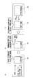
これに対して、有機汚泥の脱水方法として、例えば、図16(a)に示すように、常温常圧において気体であるジメチルエーテルを有機汚泥に混合して、この有機汚泥を加圧容器101内に供給し、加圧容器101内を0.78MPaに加圧してジメチルエーテルを液化し、液化したジメチルエーテルと有機汚泥中の有機物の内包水とを置換して、細胞膜内の水を外部に取り出すとともに、液化したジメチルエーテルを細胞膜内に取り入れる。
その後、図16(b)に示すように、加圧容器101内の圧力を開放して常温常圧に戻すことにより、ジメチルエーテルを気化させ、気化したジメチルエーテルを回収し、図16(c)に示すように、加圧容器101内から有機汚泥と水とを取り出して固液分離装置102で固液分離する方法がある。このような方法によって、細胞膜内の水(内包水)を脱水することができ、有機汚泥の含水率を低下させることができる。
尚、前記のような脱水方法は例えば下記特許文献1に記載されている。
尚、前記のような脱水方法は例えば下記特許文献1に記載されている。
しかしながら前記の従来形式では、加圧してジメチルエーテルを液化し、液体のジメチルエーテルと内包水とを置換しているため、加圧容器101は第一種圧力容器となり、製造や取り扱いに安全上の注意を要し、第一種圧力容器に係る安全管理が煩わしいといった問題がある。
本発明は、圧力容器を用いずに有機汚泥の含水率を容易に低下させることができる有機汚泥の脱水方法および脱水設備を提供することを目的とする。
本発明は、圧力容器を用いずに有機汚泥の含水率を容易に低下させることができる有機汚泥の脱水方法および脱水設備を提供することを目的とする。
前記目的を達成するために、本第1発明は、細胞膜を有する有機物を含む有機汚泥の脱水方法であって、
常温常圧下において液体であり揮発性を有する有機溶媒を、有機汚泥と混合する混合工程を行い、
有機溶媒を混合した有機汚泥を、加温手段が備えられた脱水機の脱水部に供給して脱水する脱水工程を行い、
前記脱水工程において、脱水部の有機汚泥を有機溶媒の沸点以上の第1所定温度に加温して、有機汚泥に混合されている有機溶媒を気化させ、
気化した有機溶媒を脱水部から排出して回収するものである。
常温常圧下において液体であり揮発性を有する有機溶媒を、有機汚泥と混合する混合工程を行い、
有機溶媒を混合した有機汚泥を、加温手段が備えられた脱水機の脱水部に供給して脱水する脱水工程を行い、
前記脱水工程において、脱水部の有機汚泥を有機溶媒の沸点以上の第1所定温度に加温して、有機汚泥に混合されている有機溶媒を気化させ、
気化した有機溶媒を脱水部から排出して回収するものである。
これによると、有機汚泥中の有機物の細胞膜が有機溶媒によって溶解されて傷付くため、脱水機を用いて内包水を脱水することが可能になり、有機汚泥の含水率を容易に低下させることができる。また、加温により液体の粘性が低下するため、有機汚泥の脱水速度および脱溶媒速度が高くなる。さらに、有機溶媒は常温常圧下において液体であるため、有機溶媒を混合した有機汚泥を加圧容器内で加圧する必要は無く、第一種圧力容器に係る煩わしい安全管理が不要になる。
本第2発明における有機汚泥の脱水方法は、有機溶媒は水の沸点よりも低い沸点を有し、
第1所定温度は有機溶媒の沸点以上で且つ水の沸点未満であるものである。
これによると、脱水工程において、脱水部の有機汚泥を第1所定温度に加温することにより、有機汚泥に混合されている有機溶媒は気化するが、有機汚泥中の水は気化せずに液体のままの状態に保たれる。このため、水を蒸発させることなく、水を液体のままで有機汚泥から分離することができ、分離に要するエネルギーを低減することができる。
第1所定温度は有機溶媒の沸点以上で且つ水の沸点未満であるものである。
これによると、脱水工程において、脱水部の有機汚泥を第1所定温度に加温することにより、有機汚泥に混合されている有機溶媒は気化するが、有機汚泥中の水は気化せずに液体のままの状態に保たれる。このため、水を蒸発させることなく、水を液体のままで有機汚泥から分離することができ、分離に要するエネルギーを低減することができる。
本第3発明における有機汚泥の脱水方法は、脱水部を有機溶媒の沸点未満の第2所定温度にした状態で、脱水部へ有機汚泥の供給を開始し、
供給開始後、脱水部の有機汚泥を第1所定温度に加温するものである。
これによると、脱水機の脱水部へ有機汚泥の供給が開始されたときは、脱水部は第2所定温度であるため、有機汚泥の供給開始の際に、有機汚泥に混合されている有機溶媒が突沸するのを防止することができる。これにより、有機溶媒が急激に気化するのを抑制して、気化した有機溶媒が一時的に大量発生するのを防止することができる。従って、気化した有機溶媒を確実且つ十分に回収することが可能であり、気化した有機溶媒が回収し切れずに放散して脱水部から脱水機の外部に漏出するのを防止することができる。
供給開始後、脱水部の有機汚泥を第1所定温度に加温するものである。
これによると、脱水機の脱水部へ有機汚泥の供給が開始されたときは、脱水部は第2所定温度であるため、有機汚泥の供給開始の際に、有機汚泥に混合されている有機溶媒が突沸するのを防止することができる。これにより、有機溶媒が急激に気化するのを抑制して、気化した有機溶媒が一時的に大量発生するのを防止することができる。従って、気化した有機溶媒を確実且つ十分に回収することが可能であり、気化した有機溶媒が回収し切れずに放散して脱水部から脱水機の外部に漏出するのを防止することができる。
本第4発明における有機汚泥の脱水方法は、気化した有機溶媒を、脱水部から吸引して排出し、気体から液体に戻して回収するものである。
これによると、有機溶媒を気体から液体に戻して回収するため、回収された液体の有機溶媒をそのまま繰り返し再利用することができる。
これによると、有機溶媒を気体から液体に戻して回収するため、回収された液体の有機溶媒をそのまま繰り返し再利用することができる。
本第5発明における有機汚泥の脱水方法は、混合工程において、有機物の細胞膜を構成する粗脂肪を溶解し、
脱水工程において、細胞膜を構成する粗脂肪が溶解したろ液を排出するものである。
これによると、有機汚泥中の有機物の細胞膜を構成する粗脂肪が有機溶媒によって溶解されて、細胞膜が傷付くため、脱水機を用いて内包水を脱水することが可能になり、有機汚泥の含水率を容易に低下させることができる。この際、有機溶媒は常温常圧下において液体であるため、有機溶媒を混合した有機汚泥を加圧容器内で加圧する必要は無く、第一種圧力容器に係る煩わしい安全管理が不要になる。
脱水工程において、細胞膜を構成する粗脂肪が溶解したろ液を排出するものである。
これによると、有機汚泥中の有機物の細胞膜を構成する粗脂肪が有機溶媒によって溶解されて、細胞膜が傷付くため、脱水機を用いて内包水を脱水することが可能になり、有機汚泥の含水率を容易に低下させることができる。この際、有機溶媒は常温常圧下において液体であるため、有機溶媒を混合した有機汚泥を加圧容器内で加圧する必要は無く、第一種圧力容器に係る煩わしい安全管理が不要になる。
本第6発明における有機汚泥の脱水方法は、細胞膜の溶解により発生する粗脂肪が有機汚泥からろ液に移行する移行率を指標にして、有機溶媒の混合割合を設定するものである。
これによると、粗脂肪の移行率を指標にして、有機溶媒の混合割合を設定することにより、適切な量の有機溶媒を用いて有機汚泥を脱水することが可能であり、有機溶媒を過剰に混合して無駄にするのを防止することができる。さらに、ろ液のBOD(生物化学的酸素要求量)を過度に上げることなく脱水効率を向上させることができるため、ろ液を処理する際の負荷が軽減される。
これによると、粗脂肪の移行率を指標にして、有機溶媒の混合割合を設定することにより、適切な量の有機溶媒を用いて有機汚泥を脱水することが可能であり、有機溶媒を過剰に混合して無駄にするのを防止することができる。さらに、ろ液のBOD(生物化学的酸素要求量)を過度に上げることなく脱水効率を向上させることができるため、ろ液を処理する際の負荷が軽減される。
本第7発明における有機汚泥の脱水方法は、粗脂肪の移行率が4重量%以上から60重量%以下の所定範囲になるように、有機溶媒の混合割合を設定するものである。
これによると、前記4重量%以上から60重量%以下の所定範囲において、粗脂肪の移行率が増えるほど、脱水工程後の有機汚泥の含水率が低下する関係が保たれる。従って、前記4重量%以上から60重量%以下の所定範囲においては、有機溶媒の混合割合を増やすことにより、有機汚泥からろ液への粗脂肪の移行率が増加し、脱水工程後の有機汚泥の含水率が低下する。従って、移行率を前記4重量%以上から60重量%以下の所定範囲にすることにより、適切な量の有機溶媒を用いて有機汚泥を脱水することが可能であり、有機溶媒を過剰に混合して無駄にするのを防止することができる。
これに対して、移行率が60重量%より大きい範囲においては、有機溶媒の混合割合を増やしても、脱水工程後の有機汚泥の含水率が低下せず、有機溶媒を過剰に混合して有機溶媒を無駄にすることになる。
また、移行率が4重量%未満の範囲においては、有機溶媒の混合割合を増やしても、脱水工程後の有機汚泥の含水率に変化が無く、有機溶媒を混合しても脱水効果はほとんど無いため、有機溶媒が無駄になる。
本第8発明における有機汚泥の脱水方法は、有機溶媒の混合割合を、有機汚泥の含水量と有機溶媒の量との和に対して、30重量%以上から75重量%以下の所定範囲に設定するものである。
これによると、有機溶媒の混合割合を30重量%以上から75重量%以下の所定範囲に設定することにより、移行率が4重量%以上から60重量%以下の所定範囲になる。このため、適切な量の有機溶媒を用いて有機汚泥を脱水することが可能となり、有機溶媒を過剰に混合して無駄にするのを防止することができる。さらに、ろ液のBODを一定範囲に抑えることができるため、ろ液を外部へ排水できるように処理する際の負荷の増加を抑えることができる。
これによると、有機溶媒の混合割合を30重量%以上から75重量%以下の所定範囲に設定することにより、移行率が4重量%以上から60重量%以下の所定範囲になる。このため、適切な量の有機溶媒を用いて有機汚泥を脱水することが可能となり、有機溶媒を過剰に混合して無駄にするのを防止することができる。さらに、ろ液のBODを一定範囲に抑えることができるため、ろ液を外部へ排水できるように処理する際の負荷の増加を抑えることができる。
本第9発明における有機汚泥の脱水方法は、有機溶媒はエタノールであり、
エタノールの混合割合を、有機汚泥の含水量とエタノールの量との和に対して、30重量%以上から70重量%以下の所定範囲に設定するものである。
これによると、エタノールの混合割合を30重量%以上から70重量%以下の所定範囲に設定することにより、移行率が4重量%以上から60重量%以下の所定範囲になり、適切な量のエタノールを用いて有機汚泥を脱水することが可能となる。
エタノールの混合割合を、有機汚泥の含水量とエタノールの量との和に対して、30重量%以上から70重量%以下の所定範囲に設定するものである。
これによると、エタノールの混合割合を30重量%以上から70重量%以下の所定範囲に設定することにより、移行率が4重量%以上から60重量%以下の所定範囲になり、適切な量のエタノールを用いて有機汚泥を脱水することが可能となる。
本第10発明における有機汚泥の脱水方法は、有機溶媒はメタノールであり、
メタノールの混合割合を、有機汚泥の含水量とメタノールの量との和に対して、30重量%以上から75重量%以下の所定範囲に設定するものである。
これによると、メタノールの混合割合を30重量%以上から75重量%以下の所定範囲に設定することにより、移行率が4重量%以上から60重量%以下の所定範囲になり、適切な量のメタノールを用いて有機汚泥を脱水することが可能となる。
メタノールの混合割合を、有機汚泥の含水量とメタノールの量との和に対して、30重量%以上から75重量%以下の所定範囲に設定するものである。
これによると、メタノールの混合割合を30重量%以上から75重量%以下の所定範囲に設定することにより、移行率が4重量%以上から60重量%以下の所定範囲になり、適切な量のメタノールを用いて有機汚泥を脱水することが可能となる。
本第11発明は、第1発明から第10発明のいずれか1項に記載の有機汚泥の脱水方法に用いられる脱水設備であって、
有機溶媒と有機汚泥とを混合する混合部と、有機溶媒を混合した有機汚泥を脱水する脱水機とが備えられ、
脱水機は、脱水部と、脱水部に供給された有機汚泥を加温する加温手段とを有し、
混合工程が混合部において行われ、
脱水工程が脱水機において行われるものである。
有機溶媒と有機汚泥とを混合する混合部と、有機溶媒を混合した有機汚泥を脱水する脱水機とが備えられ、
脱水機は、脱水部と、脱水部に供給された有機汚泥を加温する加温手段とを有し、
混合工程が混合部において行われ、
脱水工程が脱水機において行われるものである。
以上のように本発明によると、有機汚泥を脱水する際、圧力容器を用いずに有機汚泥の含水率を低下させることができるため、第一種圧力容器に係る安全管理が不要になる。
以下、本発明における実施の形態を、図面を参照して説明する。
(第1の実施の形態)
(第1の実施の形態)
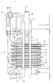
第1の実施の形態において、図1は、下水処理における有機汚泥の脱水設備1を模式的に示す図である。これによると、脱窒槽2において脱窒された有機汚泥を濃縮する濃縮機3と、濃縮された有機汚泥にアルコール系溶媒Aを混合する混合槽4(混合部の一例)と、アルコール系溶媒Aが混合された有機汚泥Bを脱水する無端ろ布走行式のフィルタープレス5(脱水機の一例)と、気化されたアルコール系溶媒Aを液体に戻す凝縮器6と、フィルタープレス5から排出されたろ液から液体のアルコール系溶媒Aを分離して回収する加熱蒸留器7とを有している。尚、有機汚泥には、細胞膜を有する有機物が含まれている。
アルコール系溶媒Aは、常温常圧(25℃,1気圧)下において液体であり揮発性を有する有機溶媒の一例であって、具体例として、エタノールAが用いられる。エタノールAの沸点は、78℃であり、水の沸点(100℃)よりも低い。尚、ここで、沸点とは、1気圧における標準沸点を意味する。
濃縮機3には例えばベルト濃縮機等が用いられる。混合槽4には、有機汚泥とエタノールAとを攪拌して混合する攪拌機等が備えられている。
濃縮機3には例えばベルト濃縮機等が用いられる。混合槽4には、有機汚泥とエタノールAとを攪拌して混合する攪拌機等が備えられている。
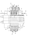
図2に示すように、フィルタープレス5は、固定フレーム15と、固定フレーム15に対して接近したり離間することが可能な可動フレーム16と、これら両フレーム15,16間に互いに接近離間自在に配列された複数のろ板17と、無端状のろ布18と、ろ板17を互いに接近離間させてろ板17間を開閉する開閉装置19と、ろ布18を一方向Dへ走行させるろ布駆動装置29と、加温手段20とを有している。図3に示すように、ろ布18は、ローラ21に掛け渡されて、ろ板17間において逆U字状に配置されている。各ろ板17間において、相対向する一対のろ布18間にろ室22(脱水部の一例)が形成されている。また、開閉装置19は、可動フレーム16を移動させるシリンダ23を有している。
図4に示すように、固定フレーム15と一端部のろ板17とがリンク24で連結され、同様に、可動フレーム16と他端部のろ板17とがリンク25で連結されている。さらに、各ろ板17同士がリンク機構26で連結されている。
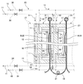
図5~図7に示すように、各ろ板17には、表裏のいずれか片面に開口する凹部27が形成され、凹部27内にはダイヤフラム28が設けられている。また、各ろ板17には、温水10を供給してダイヤフラム28を膨張させる第1の温水供給経路30と、温水10を排出してダイヤフラム28を収縮させる第1の温水排出経路31とが接続されている。
さらに、各ろ板17には、温水11が流れる加温通路32が形成されており、温水11を加温通路32に供給する第2の温水供給経路33と、温水11を加温通路32から排出する第2の温水排出経路34とが接続されている。尚、加温手段20は第1および第2の温水供給経路30,33と第1および第2の温水排出経路31,34と加温通路32とによって構成されている。
尚、第1,第2の温水供給経路30,33および第1,第2の温水排出経路31,34は個別の経路として説明したが、第1,第2の温水供給経路30,33を一つの経路にまとめ、第1,第2の温水排出経路31,34を一つの経路にまとめてもよい。
図3,図4,図8,図9に示すように、各ろ板17には、有機汚泥Bをろ室22に注入する汚泥注入通路36が形成されている。また、各ろ板17間には、口金部材37(フィードピース)がリンク機構26に支持されて配設されている。各口金部材37には、汚泥注入通路36から分岐してろ室22に通じる分岐通路38が形成されている。
また、各ろ板17には、ろ室22において圧搾された有機汚泥Bから出てくるろ液Cを排出するろ液排出通路40(図3参照)が形成されている。図8,図9に示すように、固定フレーム15には、隣接するろ板17の汚泥注入通路36に連通する汚泥注入口41と、ろ液排出通路40に連通するろ液排出口(図示省略)とが形成されている。また、可動フレーム16には、隣接するろ板17の汚泥注入通路36に連通する回収用流体注入口43が形成されている。
図1,図2,図4,図9に示すように、混合槽4とフィルタープレス5の汚泥注入口41との間には、混合槽4内の有機汚泥Bをフィルタープレス5へ供給する汚泥供給経路45が接続されている。汚泥供給経路45は、配管等からなり、途中に汚泥供給用ポンプ46と汚泥供給用弁47とが設けられている。また、汚泥供給経路45には、汚泥供給経路45から分岐して混合槽4へ連通する第1返送経路48と、汚泥供給経路45から分岐して脱窒槽2へ連通する第2返送経路49とが接続されている。尚、第1および第2返送経路48,49には第1および第2返送用弁50,51が設けられている。
フィルタープレス5の回収用流体注入口43には、圧縮空気12(回収用流体の一例)を供給する回収用流体供給経路44が接続されている。回収用流体供給経路44には、回収用流体供給用弁52と、コンプレッサー等からなる回収用流体供給源53とが設けられている。
図1に示すように、フィルタープレス5のろ液排出口と加熱蒸留器7との間には、フィルタープレス5から排出されたろ液Cを加熱蒸留器7へ送るろ液回収経路54が接続されている。ろ液回収経路54にはろ液回収用弁55が設けられている。また、ろ液回収経路54には、ろ液回収経路54から分岐して凝縮器6の入口に連通する第1溶媒回収経路56aと、凝縮器6の出口からろ液回収経路54に合流する第2溶媒回収経路56bとが接続されている。尚、第1溶媒回収経路56aには溶媒回収用弁57が設けられている。
混合槽4と加熱蒸留器7との間には、加熱蒸留器7においてろ液Cから分離回収された液体のエタノールAを混合槽4へ返送する第1溶媒返送経路58が設けられている。また、脱窒槽2と加熱蒸留器7との間には、前記液体のエタノールAを脱窒槽2へ返送する第2溶媒返送経路59が設けられている。第2溶媒返送経路59は第1溶媒返送経路58から分岐して設けられ、第1および第2溶媒返送経路58,59には第1および第2返送用弁60,61が設けられている。
尚、微生物等の有機物の細胞膜は一般に脂質二重層で構成されている。本発明者らは、脂質を溶解する作用を持つ有機溶媒を使用して、脂質である脂質二重層の一部を溶解し、有機汚泥を脱水して得られるろ液中の粗脂肪に着目した。この粗脂肪は脂質二重層を起源としており、細胞膜が溶解した指標として、ろ液中の粗脂肪と脱水後の有機汚泥の含水率との間に関係性を見い出した。この関係性を利用した有機汚泥の脱水方法を、本実施の形態に基づいて、以下に説明する。
前以て、フィルタープレス5の開閉装置19のシリンダ23を作動し、可動フレーム16を固定フレーム15に向って接近させ、図5,図9に示すように、各ろ板17間を閉じておく。また、温水11を、第2の温水供給経路33から各ろ板17の加温通路32に供給し、加温通路32から第2の温水排出経路34へ排出する。加温通路32に温水11を通水した状態に保ち、加温通路32の温水11によってろ室22内を第1所定温度に加温しておく。
尚、第1所定温度とは、エタノールAの沸点以上で且つ水の沸点未満の温度であり、すなわち78℃以上で且つ100℃未満の温度である。
尚、第1所定温度とは、エタノールAの沸点以上で且つ水の沸点未満の温度であり、すなわち78℃以上で且つ100℃未満の温度である。
そして、図1に示すように、汚泥供給用弁47とろ液回収用弁55と第1返送用弁60とを開き、第1および第2返送用弁50,51と回収用流体供給用弁52と溶媒回収用弁57と第2返送用弁61とを閉じ、脱窒槽2で脱窒された有機汚泥を濃縮機3により濃縮し、混合槽4において、濃縮された有機汚泥に液体のエタノールAを混合する混合工程を行う。この時、回収したエタノールAが必要な量よりも不足する場合には、新たなエタノールAを追加して使用する。その後、汚泥供給用ポンプ46を駆動することにより、エタノールAを混合した有機汚泥Bは、混合槽4から汚泥供給経路45を通ってフィルタープレス5に供給され、脱水工程により脱水される。脱水工程は、以下のようなろ過工程と圧搾工程と乾燥工程とからなる。
すなわち、ろ過工程では、図9に示すように、有機汚泥Bは、汚泥供給経路45を経て、フィルタープレス5の汚泥注入口41から各ろ板17の汚泥注入通路36を通り、汚泥注入通路36から各口金部材37の分岐通路38を経て、各ろ室22に注入される。これにより、図5に示すように、有機汚泥Bが各ろ室22においてろ過される。この際、ろ室22は、加温通路32を通る温水11により、第1所定温度に加温されるため、ろ室22内に注入された有機汚泥Bも第1所定温度に加温される。
ろ過工程を行った後、図6に示すように、温水10を、第1の温水供給経路30から各ろ板17に供給し、ダイヤフラム28の内側空間13に通水する。これにより、ダイヤフラム28が膨張して、ろ室22内の有機汚泥Bが圧搾されて脱水される。この圧搾工程を行っている際にも、引き続き温水11を加温通路32に通水することにより、ろ室22内の有機汚泥Bが第1所定温度に加温されている。つまり、有機汚泥Bは、ろ室22内に留まっている間、第1所定温度に加温され続けている。
前記ろ過工程と圧搾工程とにおいて発生したろ液Cは、各ろ板17のろ液排出通路40を通り、ろ液排出口から排出され、図1に示すように、ろ液回収経路54を経て加熱蒸留器7へ送られる。尚、ろ液Cには水と液体のエタノールAとが含まれている。
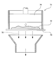
さらに、前記圧搾工程を行った後、図7に示すように、引き続き温水11を加温通路32に通水した状態で、第1の温水供給経路30からダイヤフラム28の内側空間13への温水10の供給を停止し、ダイヤフラム28の内側空間13の温水10を第1の温水排出経路31へ排出して、内側空間13を空にする。これにより、ダイヤフラム28は収縮してろ布18から離間し、ダイヤフラム28とろ布18との間に乾燥用空間14が形成される。この際、ろ室22内の有機汚泥Bが加温通路32の温水11により第1所定温度に加温されているため、有機汚泥Bに混合されているエタノールAが気化して乾燥用空間14に取り出される。
尚、気化したエタノールAは主に前記のような乾燥工程で回収されるが、ろ過工程や圧搾工程においても、吸引することによって回収することが可能であり、回収効率がさらに向上する。
このような乾燥工程を行う際、図1に示すように、ろ液回収用弁55を閉じるとともに溶媒回収用弁57を開いておき、気化したエタノールAを排気用ポンプ(図示省略)等で吸引してろ室22内から排出する。これにより、気化したエタノールAは、各ろ板17の乾燥用空間14からろ液排出通路40を通り、フィルタープレス5のろ液排出口から排出され、ろ液回収経路54から分岐して第1溶媒回収経路56aを通り、凝縮器6に供給される。このようにして凝縮器6に供給されたエタノールAは、気体から液体に凝縮された後、第2溶媒回収経路56bを通ってろ液回収経路54に合流し、加熱蒸留器7へ送られる。
前記ろ過工程と圧搾工程とにおいてフィルタープレス5から排出されたろ液Cと、乾燥工程においてフィルタープレス5から排出された後に凝縮器6で凝縮されて得られた液体のエタノールAとは、加熱蒸留器7に集められ、纏めて蒸留される。これにより、ろ液Cが水とエタノールAとに分離され、液体のエタノールAが、回収されて、加熱蒸留器7から第1溶媒返送経路58を通って混合槽4に返送される。
また、図6で示したようにフィルタープレス5で乾燥工程を行った後、引き続き各ろ板17間を閉じた状態で、図1に示すように、汚泥供給用弁47と第2返送用弁51とろ液回収用弁55と溶媒回収用弁57とを閉じ、第1返送用弁50と回収用流体供給用弁52とを開き、圧縮空気12を回収用流体供給源53からフィルタープレス5に供給する。この際、図1,図9に示すように、圧縮空気12は、回収用流体供給源53から回収用流体供給経路44を通り、回収用流体注入口43から各ろ板17の汚泥注入通路36を経て汚泥注入口41に達し、汚泥注入口41から汚泥供給経路45を逆流し、汚泥供給経路45から第1返送経路48に分岐して流れ、混合槽4へ排出される。
その後、フィルタープレス5の開閉装置19のシリンダ23を作動し、可動フレーム16を固定フレーム15から離間させ、図2,図4,図8に示すように、各ろ板17間を開く。そして、ろ布駆動装置29でろ布18を一方向Dへ走行させて、脱水ケーキ63をろ布18間のろ室22から下方へ排出する。
前記のような有機汚泥の脱水方法では、エタノールAは、図10のグラフに示すように比誘電率が低く、細胞膜を構成する脂質を溶解する作用を有する。これにより、混合槽4において、有機汚泥に液体のエタノールAを混合する混合工程を行うことによって、有機汚泥中の有機物の細胞膜の一部がエタノールAによって溶解されて傷付く。このため、その後の脱水工程において、細胞膜が破損して内包水が細胞膜の外部に排出され、これにより、フィルタープレス5を用いて有機汚泥中の有機物の内包水を脱水することが可能になり、有機汚泥の含水率を容易に低下させることができる。
また、図5~図7に示すように、フィルタープレス5のろ室22内の有機汚泥Bを第1所定温度に加温することにより、水の粘性およびエタノールAの粘性が低下するため、有機汚泥Bの脱水速度および脱溶媒速度が高くなる。さらに、エタノールAは常温で液体のため、エタノールAを混合した有機汚泥Bを加圧容器内で加圧する必要は無く、これにより、加圧のための第一種圧力容器に係る煩わしい安全管理が不要になる。
また、図7に示すように、フィルタープレス5の乾燥工程において、ろ室22内の有機汚泥Bが第1所定温度に加温されている。第1所定温度はエタノールAの沸点以上で且つ水の沸点未満であるため、ろ室22内の有機汚泥Bに混合されているエタノールAは気化するが、有機汚泥B中の水は気化せずに液体のままの状態に保たれる。つまり、水は、蒸発することなく、液体のままで有機汚泥Bから分離することができ、有機汚泥Bからの水の分離に要するエネルギーを低減することができる。
また、フィルタープレス5から取り出された気化したエタノールAは、液体に戻された後、混合槽4に返送される。つまり、エタノールAは繰り返し再利用することができる。
さらに、図1に示すように、圧縮空気12を、フィルタープレス5から汚泥供給経路45と第1返送経路48とを通して、混合槽4へ流すことにより、汚泥供給経路45に残留している有機汚泥Bが、圧縮空気12の流れに伴って、第1返送経路48を通り混合槽4へ返送される。これにより、返送された有機汚泥B中に混合されているエタノールAも混合槽4へ戻されるため、汚泥供給経路45に残留していたエタノールAを回収して再利用することができる。このことから、混合槽4へ新たに追加して使用するエタノールAの量を減らすことができる。さらに、汚泥供給経路45を洗浄する効果もあり、汚泥供給経路45が閉塞するのを防止することができる。
前記のような脱水方法では、フィルタープレス5を用いた脱水工程において、フィルタープレス5から排出されるろ液は、細胞膜の一部が溶解した粗脂肪を含んでいる。このように細胞膜の溶解により発生する粗脂肪が有機汚泥からろ液に移行する移行率を指標にして、有機汚泥へのエタノールAの混合割合を以下のように設定している。
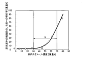
すなわち、図12のグラフに基づいて、脱水工程後の有機汚泥の含水率から必要な粗脂肪の移行率を求め、この移行率から図11のグラフに基づいてエタノール濃度を求める。図11のグラフは、系内エタノール濃度と原汚泥中の粗脂肪のろ液への移行率との関係を示すものである。ここで、系内エタノール濃度とは、有機汚泥の含水量とエタノールの量との和に対するエタノールAの混合割合であって、混合槽4に供給される有機汚泥(原汚泥)の含水量をW1[g]とし、混合槽4に供給されるエタノールAの量をW2[g]とすると、下記の関係式(1)で示される。
系内のエタノール濃度=100×W2/(W1+W2) 式(1)
系内のエタノール濃度=100×W2/(W1+W2) 式(1)
また、前記原汚泥中の粗脂肪のろ液への移行率とは、粗脂肪が原汚泥からろ液へ移行する比率である。混合槽4に供給される有機汚泥(原汚泥)の量をE[g]とし、この原汚泥中に含まれている粗脂肪の濃度をe[mg/g]とし、前記E[g]の有機汚泥をフィルタープレス5で脱水して得られるろ液の量をF[g]とし、ろ液中に含まれている粗脂肪の濃度をf[mg/g]とすると、下記の関係式(2)で示される。
移行率=(100×F×f)/(E×e) 式(2)
尚、前記粗脂肪の濃度e,fは測定により求められる。
移行率=(100×F×f)/(E×e) 式(2)
尚、前記粗脂肪の濃度e,fは測定により求められる。
図11のグラフにおいて、移行率が4重量%の場合、エタノールAの混合割合である系内エタノール濃度が30重量%となり、移行率が60重量%の場合、系内エタノール濃度が70重量%となる。つまり、図11のグラフに示すように、移行率が4%から60%の範囲は、系内エタノール濃度が30重量%以上から70重量%以下の所定範囲Sに対応している。
また、図12に示すグラフは、原汚泥中の粗脂肪のろ液への移行率と脱水工程後の汚泥の含水率との関係を示すものである。このグラフによると、前記移行率が4重量%以上から60重量%以下の所定範囲Tにおいて、粗脂肪のろ液への移行率が増えるほど、脱水工程後の有機汚泥の含水率が低下する関係が保たれる。従って、図11と図12から、前記移行率が4重量%以上から60重量%以下の所定範囲Tにおいては、エタノールの混合割合すなわち系内エタノール濃度の増加に応じて、粗脂肪のろ液への移行率が増加し、脱水工程後の有機汚泥の含水率が低下することは明らかである。従って、移行率を前記所定範囲Tにすることにより、適切な量のエタノールを用いて有機汚泥を脱水することが可能となり、エタノールAを過剰に有機汚泥に混合して無駄に使用するのを防止することができる。
また、BODの一つの原因である粗脂肪のろ液への移行率を前記所定範囲Tとすることで、ろ液のBODを一定範囲に抑えることができる。つまり、粗脂肪をはじめとするろ液のBODの増加を抑制し、ろ液を外部へ排水するために処理する際の排水処理の負荷の増加を抑えることもできる。
これに対して、図11のグラフに示すように、仮に、エタノール濃度が70重量%より高いと、移行率が60重量%より大きくなる。図12のグラフに示すように、移行率が60重量%より大きい範囲においては、エタノールAの混合割合を増やしても、脱水工程後の有機汚泥の含水率は低下しない。つまり、エタノールAを70重量%より多く混合しても、多く混合されたエタノールAは、脱水に寄与せず、無駄になる。さらに、エタノールAを多く混合することにより、粗脂肪のろ液への移行が増加し、ろ液のBODも増加し、排水処理の負荷も増加し、エネルギーの無駄が生じる。
また、図11のグラフに示すように、エタノール濃度が30重量%より低いと、粗脂肪のろ液への移行率は4重量%より小さくなる。図12のグラフに示すように、移行率が4重量%未満の範囲においては、脱水しても有機汚泥の含水率がほとんど変化せずに一定に保たれる。従って、移行率が4重量%以上となるように、エタノールAの混合割合を30重量%以上とすることで、エタノールAを混合しないときと比べて、脱水工程後の有機汚泥の含水率を約5重量%以上低下させることになる。
つまり、粗脂肪の移行率を指標にして、エタノールAの混合割合を設定することにより、適切な量のエタノールAを用いて有機汚泥を脱水することが可能となり、エタノールAを有機汚泥に過剰に混合して無駄に使用するのを防止することができる。また、ろ液のBODの増加を抑制して脱水効率を向上させることができるため、ろ液を処理する際の排水処理の負荷が軽減される。
さらに、過剰なエタノールAを有機汚泥に混合すると、過剰に混合されたエタノールAを回収するのに要するエネルギーが余分にかかり、エネルギーが無駄になる。また、エタノールAが気化して損失される量も増加するため、使用されるエタノールAの無駄が大きくなる。
尚、前記図11および図12のグラフのデータは、含水率が80重量%の原汚泥20gを試料とし、この原汚泥とエタノールAとを30分間混合した後、試験用脱水機で次第に圧力を上げ、最終的に汚泥を2MPaの圧力で15分間脱水して得られたものである。図13に示すように、試験用脱水機71は、エタノールAを混合した汚泥72をフィルター73上に載せ、上方からピストン74で汚泥72を押圧し、フィルター73を透過したろ液75を採取するものである。
前記第1の実施の形態では、図11のグラフに示すように、系内のエタノール濃度を30重量%以上から70重量%以下の所定範囲Sに設定しているが、グラフの傾きが急増する45重量%以上から70重量%以下の範囲に設定すると、より好適である。
第1の実施の形態では、第1所定温度をエタノールAの沸点より僅かに高い値に設定することにより、第1所定温度を水の沸点に近い値に設定する場合に比べて、エタノールAの突沸や水の蒸発量を抑制することができるので、好適である。
第1の実施の形態では、図1に示すように、返送経路として第1,第2返送経路48,49を設け、溶媒返送経路として第1,第2溶媒返送経路58,59を設けているが、これらの経路48,49,58,59を全て設ける必要はなく、第1,第2返送経路48,49のうちのいずれか1つの返送経路又は第1,第2溶媒返送経路58,59のうちのいずれか1つの溶媒返送経路があればよい。
また、第1の実施の形態では、温水11を用いてろ室22を第1所定温度に加温することにより、有機汚泥Bを第1所定温度に加温しているが、ろ室22からの放熱を見込んでろ室22を第1所定温度以上に加温することにより、有機汚泥Bを第1所定温度に加温してもよい。
また、第1の実施の形態では、温水11の温度を制御対象とし、放熱を考慮して温水11をエタノールAの沸点以上の温度に適宜調節することにより、有機汚泥Bの温度がエタノールAの沸点以上で且つ水の沸点未満の温度(すなわち第1所定温度)になるように制御することができる。この際、外気温又は温水11の温度を計測する温度計の取付箇所等に応じて、温水11の温度を第1所定温度よりどの程度高温に設定するかが決定される。
(第2の実施の形態)
また、第1の実施の形態では、温水11を用いてろ室22を第1所定温度に加温することにより、有機汚泥Bを第1所定温度に加温しているが、ろ室22からの放熱を見込んでろ室22を第1所定温度以上に加温することにより、有機汚泥Bを第1所定温度に加温してもよい。
また、第1の実施の形態では、温水11の温度を制御対象とし、放熱を考慮して温水11をエタノールAの沸点以上の温度に適宜調節することにより、有機汚泥Bの温度がエタノールAの沸点以上で且つ水の沸点未満の温度(すなわち第1所定温度)になるように制御することができる。この際、外気温又は温水11の温度を計測する温度計の取付箇所等に応じて、温水11の温度を第1所定温度よりどの程度高温に設定するかが決定される。
(第2の実施の形態)
前記第1の実施の形態では、フィルタープレス5のろ室22を予め第1所定温度(すなわち、エタノールAの沸点以上で且つ水の沸点未満の温度)に加温した状態で、有機汚泥Bをろ室22に注入しているが、以下に説明する第2の実施の形態では、ろ室22をエタノールAの沸点未満の第2所定温度に加温した状態で、有機汚泥Bをろ室22に注入し始め、注入開始後、ろ室22を第2所定温度から第1所定温度に加温する。
すなわち、前以て、第2所定温度の温水11を、フィルタープレス5の加温通路32(図5参照)に通水した状態に保ち、加温通路32の温水11によってろ室22内を第2所定温度に加温しておく。この状態で、有機汚泥Bをろ室22に注入し始め、注入開始後、温水11を第2所定温度から昇温させながら引き続き加温通路32に通水して、ろ室22を第2所定温度から第1所定温度に加温する。これにより、ろ室22内に注入された有機汚泥Bは第2所定温度から第1所定温度に加温に加温される。
尚、前記のようにろ室22を第2所定温度から第1所定温度に昇温させるタイミングは、図5で示したフィルタープレス5のろ過工程の途中で行うが、図6で示した圧搾工程中又は図7で示した乾燥工程中に行ってもよい。尚、第2所定温度としては、エタノールAの場合、73℃に設定されているが、沸点未満であればこの温度に限定されるものではない。
以下、前記構成における作用を説明する。
以下、前記構成における作用を説明する。
ろ室22へ有機汚泥Bの注入が開始されたときは、ろ室22は第2所定温度であるため、有機汚泥Bの注入開始の際に、有機汚泥Bに混合されているエタノールAが突沸するのを防止することができる。これにより、エタノールAが急激に気化するのを抑制して、気化したエタノールAが一時的且つ過剰に大量発生するのを防止することができる。従って、気化したエタノールAを確実且つ十分に凝縮器6で凝縮し液体に戻して回収することが可能であり、気化したエタノールAが回収し切れずに放散してろ室22からフィルタープレス5の外部に漏出するのを防止することができる。
(第3の実施の形態)
(第3の実施の形態)
前記第1の実施の形態では、フィルタープレス5で脱水工程を行った後、回収用流体供給源53から圧縮空気12をフィルタープレス5に供給して混合槽4へ排出しているが、以下に説明する第3の実施の形態では、フィルタープレス5で脱水工程を行った後、回収用流体供給源53から圧縮空気12をフィルタープレス5に供給して脱窒槽2へ排出する。
すなわち、図1に示すように、フィルタープレス5の各ろ板17間を閉じた状態で、汚泥供給用弁47と第1返送用弁50とろ液回収用弁55と溶媒回収用弁57とを閉じ、第2返送用弁51と回収用流体供給用弁52とを開き、圧縮空気12を回収用流体供給源53からフィルタープレス5に供給する。この際、圧縮空気12は、回収用流体供給源53から回収用流体供給経路44を通り、回収用流体注入口43から各ろ板17の汚泥注入通路36を経て汚泥注入口41に達する(図9参照)。さらに、圧縮空気12は、汚泥注入口41から汚泥供給経路45を逆流し、汚泥供給経路45から第2返送経路49に分岐して流れ、脱窒槽2へ排出される。
これにより、汚泥供給経路45に残留している有機汚泥Bが、圧縮空気12の流れに伴って、第2返送経路49を通り脱窒槽2へ返送される。従って、返送された有機汚泥B中に混合されているエタノールAも脱窒槽2へ供給され、エタノールAが脱窒槽2内の脱窒菌の栄養源になる。このため、エタノールAを有効利用することができる。
(第4の実施の形態)
(第4の実施の形態)
前記各実施の形態では、液体のエタノールAを、加熱蒸留器7から第1溶媒返送経路58を通じて混合槽4に返送しているが、以下に説明する第4の実施の形態では、液体のエタノールAを、加熱蒸留器7から第2溶媒返送経路59を通じて脱窒槽2に供給する。
すなわち、図1に示すように、第1返送用弁60を閉じ、第2返送用弁61を開くことにより、液体のエタノールAが、加熱蒸留器7から第2溶媒返送経路59を通って脱窒槽2に供給される。これにより、エタノールAが脱窒槽2内の脱窒菌の栄養源になり、エタノールAを有効利用することができる。
(第5の実施の形態)
(第5の実施の形態)
前記第1~第4の実施の形態では、有機溶媒の一例としてエタノールAを用いたが、以下に説明する第5の実施の形態では、有機溶媒の別の例としてメタノールを用いている。尚、メタノールの沸点は、65℃であり、水の沸点(100℃)よりも低い。
従って、メタノールを用いた場合、第1所定温度は、メタノールの沸点以上で且つ水の沸点未満の温度となり、すなわち65℃以上で且つ100℃未満の温度となる。また、第2所定温度は、60℃に設定されるが、沸点未満であればこの温度に限定されるものではない。
また、メタノールを用いた場合、系内メタノール濃度と原汚泥中の粗脂肪のろ液への移行率との関係は図14のグラフで示され、原汚泥中の粗脂肪のろ液への移行率と脱水工程後の汚泥の含水率との関係は図15のグラフで示される。
図15のグラフに示すように、粗脂肪のろ液への移行率が4重量%以上から60重量%以下の所定範囲Tにおいて、粗脂肪のろ液への移行率が増えるほど、脱水工程後の有機汚泥の含水率が低下する関係が保たれる。また、図14のグラフに示すように、移行率が4重量%以上から60重量%以下の所定範囲Tは、系内メタノール濃度が30重量%以上から75重量%以下の所定範囲Sに対応している。
従って、系内メタノール濃度が30重量%以上から75重量%以下の所定範囲Sになるようにメタノールを有機汚泥に混合することにより、粗脂肪のろ液への移行率が4重量%以上から60重量%以下の所定範囲Tになり、適切な量のメタノールを用いて有機汚泥を脱水することが可能となり、メタノールを過剰に有機汚泥に混合して無駄に使用するのを防止することができる。
また、メタノールを75重量%より多く混合しても、多く混合されたメタノールは、脱水に寄与せず、無駄になる。さらに、粗脂肪のろ液への移行率が4重量%未満の範囲においては、脱水しても有機汚泥の含水率がほとんど変化せずに一定に保たれる。つまり、移行率が4重量%以上となるように、メタノールの混合割合を30重量%以上とすることで、メタノールを混合しないときと比べて、脱水工程後の有機汚泥の含水率を約5重量%以上低下させることになる。
尚、図10のグラフは、エタノール、メタノールおよび他の溶媒の比誘電率を示しており、溶媒は、比誘電率が低いほど、脂質を溶かす能力が高い。従って、エタノールは、メタノールと比べて、細胞膜を溶解する能力が優れている。但し、メタノールは、エタノールよりも分子量が低いので、細胞膜の表面を溶解するだけではなく、細胞膜を透過しながら細胞膜の内部を溶解する能力が高いと考えられる。このため、エタノールよりもメタノールを使用した方が、細胞膜が弱くなり、脱水工程において細胞膜が破損し易くなる。このため、メタノールを使用した方が、エタノールを使用したときの移行率よりも低い移行率で、同じ含水率まで脱水することができる。
前記各実施の形態では、脱水機の一例としてフィルタープレス5を用いたが、別の例として、スクリュープレスやベルトプレス等を用いてもよい。
前記各実施の形態では、有機溶媒の一例として、エタノールA又はメタノールといったアルコール系溶媒を用いたが、アセトンやヘキサンなどの、常温常圧下において液体であり、揮発性を有し、水との親和性がある有機溶媒を用いてもよい。また、このような複数種類の有機溶媒を混合したものであってもよい。
前記各実施の形態では、脱水機の一例としてフィルタープレス5を用いたが、別の例として、スクリュープレスやベルトプレス等を用いてもよい。
前記各実施の形態では、有機溶媒の一例として、エタノールA又はメタノールといったアルコール系溶媒を用いたが、アセトンやヘキサンなどの、常温常圧下において液体であり、揮発性を有し、水との親和性がある有機溶媒を用いてもよい。また、このような複数種類の有機溶媒を混合したものであってもよい。
前記各実施の形態では、図6に示すように、温水10,11を用いて加温する加温手段20を挙げたが、温水10,11の代わりに、加温した油や空気等の他の流体を用いてもよい。また、流体を使用しない他形式の加温手段、例えば電気ヒーター等を用いてもよい。
前記各実施の形態では、図1に示すように、圧縮空気12は、フィルタープレス5を経由して汚泥供給経路45に供給したが、フィルタープレス5を経由せず、フィルタープレス5の汚泥注入口41側から汚泥供給経路45に直接供給し、汚泥供給経路45のみを洗浄し、汚泥供給経路45に残留した有機汚泥Bを回収してもよい。
前記各実施の形態では、回収用流体の一例として、圧縮空気12を用いたが、水や有機溶媒等を用いてもよい。
前記各実施の形態では、回収用流体の一例として、圧縮空気12を用いたが、水や有機溶媒等を用いてもよい。
前記各実施の形態では、汚泥供給経路45等に残留する溶媒含有有機汚泥Bを逆流させる作業は、フィルタープレス5による乾燥工程の後に行っているが、別工程として、フィルタープレス5の各ろ板17の間を閉じて行ってもよい。
前記各実施の形態では、気化したエタノールAを凝縮器6で液体に戻しているが、エタノールAを気体のままで混合槽4や脱窒槽2に戻してもよい。但し、液体の状態で戻す方がエタノールAの添加量を制御し易く、より好適である。
前記各実施の形態では、加熱蒸留器7を用いて、ろ液から液体のエタノールAを分離しているが、減圧蒸留器など、水とアルコールとを分離できる他の形式の機器を用いてもよい。
前記各実施の形態では、有機汚泥は、し尿処理場や下水処理場等から発生する生の汚泥でも良いし、脱水汚泥でも良い。また、有機汚泥に含まれる有機物は植物性および動物性のどちらでも良い。
また、第1の実施の形態は、細胞膜を有する有機物を含む有機汚泥の脱水方法であって、有機汚泥と常温常圧下において液体である有機溶媒とを混合して、細胞膜を構成する粗脂肪を溶解する混合工程と、有機溶媒を混合した有機汚泥を、脱水機に供給して脱水し、細胞膜を構成する粗脂肪が溶解したろ液を排出する脱水工程とを有するものであってもよい。
また、第1の実施の形態は、細胞膜を有する有機物を含む有機汚泥の脱水方法であって、有機汚泥と常温常圧下において液体である有機溶媒とを混合して、細胞膜を構成する粗脂肪を溶解する混合工程と、有機溶媒を混合した有機汚泥を、脱水機に供給して脱水し、細胞膜を構成する粗脂肪が溶解したろ液を排出する脱水工程とを有するものであってもよい。
Claims (11)
- 細胞膜を有する有機物を含む有機汚泥の脱水方法であって、
常温常圧下において液体であり揮発性を有する有機溶媒を、有機汚泥と混合する混合工程と、
有機溶媒を混合した有機汚泥を、加温手段が備えられた脱水部に供給して脱水する脱水工程とを有し、
前記脱水工程において、脱水部の有機汚泥を有機溶媒の沸点以上の第1所定温度に加温して、有機汚泥に混合されている有機溶媒を気化させ、
気化した有機溶媒を脱水部から排出して回収することを特徴とする有機汚泥の脱水方法。 - 有機溶媒は水の沸点よりも低い沸点を有し、
第1所定温度は有機溶媒の沸点以上で且つ水の沸点未満であることを特徴とする請求項1記載の有機汚泥の脱水方法。 - 脱水部を有機溶媒の沸点未満の第2所定温度にした状態で、脱水部へ有機汚泥の供給を開始し、
供給開始後、脱水部の有機汚泥を第1所定温度に加温することを特徴とする請求項1又は請求項2記載の有機汚泥の脱水方法。 - 気化した有機溶媒を、脱水部から吸引して排出し、気体から液体に戻して回収することを特徴とする請求項1から請求項3のいずれか1項に記載の有機汚泥の脱水方法。
- 混合工程において、有機物の細胞膜を構成する粗脂肪を溶解し、
脱水工程において、細胞膜を構成する粗脂肪が溶解したろ液を排出することを特徴とする請求項1から請求項4のいずれか1項に記載の有機汚泥の脱水方法。 - 細胞膜の溶解により発生する粗脂肪が有機汚泥からろ液に移行する移行率を指標にして、有機溶媒の混合割合を設定することを特徴とする請求項5記載の有機汚泥の脱水方法。
- 粗脂肪の移行率が4重量%以上から60重量%以下の所定範囲になるように、有機溶媒の混合割合を設定することを特徴とする請求項6記載の有機汚泥の脱水方法。
- 有機溶媒の混合割合を、有機汚泥の含水量と有機溶媒の量との和に対して、30重量%以上から75重量%以下の所定範囲に設定することを特徴とする請求項5から請求項7のいずれか1項に記載の有機汚泥の脱水方法。
- 有機溶媒はエタノールであり、
エタノールの混合割合を、有機汚泥の含水量とエタノールの量との和に対して、30重量%以上から70重量%以下の所定範囲に設定することを特徴とする請求項8記載の有機汚泥の脱水方法。 - 有機溶媒はメタノールであり、
メタノールの混合割合を、有機汚泥の含水量とメタノールの量との和に対して、30重量%以上から75重量%以下の所定範囲に設定することを特徴とする請求項8記載の有機汚泥の脱水方法。 - 請求項1から請求項10のいずれか1項に記載の有機汚泥の脱水方法に用いられる脱水設備であって、
有機溶媒と有機汚泥とを混合する混合部と、有機溶媒を混合した有機汚泥を脱水する脱水機とが備えられ、
脱水機は、脱水部と、脱水部に供給された有機汚泥を加温する加温手段とを有し、
混合工程が混合部において行われ、
脱水工程が脱水機において行われることを特徴とする有機汚泥の脱水設備。
Applications Claiming Priority (4)
| Application Number | Priority Date | Filing Date | Title |
|---|---|---|---|
| JP2013-070775 | 2013-03-29 | ||
| JP2013070775A JP6238544B2 (ja) | 2013-03-29 | 2013-03-29 | 有機汚泥の脱水方法 |
| JP2013-070773 | 2013-03-29 | ||
| JP2013070773A JP6238543B2 (ja) | 2013-03-29 | 2013-03-29 | 有機汚泥の脱水方法 |
Publications (1)
| Publication Number | Publication Date |
|---|---|
| WO2014157263A1 true WO2014157263A1 (ja) | 2014-10-02 |
Family
ID=51624229
Family Applications (1)
| Application Number | Title | Priority Date | Filing Date |
|---|---|---|---|
| PCT/JP2014/058394 Ceased WO2014157263A1 (ja) | 2013-03-29 | 2014-03-26 | 有機汚泥の脱水方法および脱水設備 |
Country Status (1)
| Country | Link |
|---|---|
| WO (1) | WO2014157263A1 (ja) |
Cited By (1)
| Publication number | Priority date | Publication date | Assignee | Title |
|---|---|---|---|---|
| JP2016190176A (ja) * | 2015-03-31 | 2016-11-10 | 株式会社クボタ | 脱水方法 |
Citations (6)
| Publication number | Priority date | Publication date | Assignee | Title |
|---|---|---|---|---|
| JPS50125971A (ja) * | 1974-03-25 | 1975-10-03 | ||
| JPS55162400A (en) * | 1979-06-07 | 1980-12-17 | Agency Of Ind Science & Technol | Sludge dehydrating method by methanol |
| JP2005238078A (ja) * | 2004-02-25 | 2005-09-08 | Kurita Water Ind Ltd | 含水有機物残渣の処理方法および処理装置 |
| JP2008043903A (ja) * | 2006-08-18 | 2008-02-28 | Ebara Corp | フィルタープレスの加熱ろ板 |
| JP2010137223A (ja) * | 2003-11-19 | 2010-06-24 | Actree Corp | 汚泥の脱水乾燥装置 |
| JP2011200811A (ja) * | 2010-03-26 | 2011-10-13 | Nishimatsu Constr Co Ltd | 汚泥の減容化システムおよび減容化方法 |
-
2014
- 2014-03-26 WO PCT/JP2014/058394 patent/WO2014157263A1/ja not_active Ceased
Patent Citations (6)
| Publication number | Priority date | Publication date | Assignee | Title |
|---|---|---|---|---|
| JPS50125971A (ja) * | 1974-03-25 | 1975-10-03 | ||
| JPS55162400A (en) * | 1979-06-07 | 1980-12-17 | Agency Of Ind Science & Technol | Sludge dehydrating method by methanol |
| JP2010137223A (ja) * | 2003-11-19 | 2010-06-24 | Actree Corp | 汚泥の脱水乾燥装置 |
| JP2005238078A (ja) * | 2004-02-25 | 2005-09-08 | Kurita Water Ind Ltd | 含水有機物残渣の処理方法および処理装置 |
| JP2008043903A (ja) * | 2006-08-18 | 2008-02-28 | Ebara Corp | フィルタープレスの加熱ろ板 |
| JP2011200811A (ja) * | 2010-03-26 | 2011-10-13 | Nishimatsu Constr Co Ltd | 汚泥の減容化システムおよび減容化方法 |
Cited By (1)
| Publication number | Priority date | Publication date | Assignee | Title |
|---|---|---|---|---|
| JP2016190176A (ja) * | 2015-03-31 | 2016-11-10 | 株式会社クボタ | 脱水方法 |
Similar Documents
| Publication | Publication Date | Title |
|---|---|---|
| JP6238543B2 (ja) | 有機汚泥の脱水方法 | |
| JP6440156B2 (ja) | 有機溶剤精製システム及び方法 | |
| EP2564911B1 (en) | Pure liquid manufacturing apparatus | |
| KR20100068488A (ko) | 주로 에탄올 및 물의 혼합물을 탈수하는 방법 | |
| EP1363855B1 (de) | Verfahren und vorrichtung zur aufbereitung von flüssigkeiten | |
| EP2427264A1 (de) | Membrandestillationsvorrichtung | |
| JPH02298319A (ja) | 過蒸発により混合物の諸成分を分離・回収する方法 | |
| WO2008031401A2 (de) | Verfahren und vorrichtung zum entfeuchten und trocknen von feststoff-flüssigkeitsgemischen | |
| JP7513869B2 (ja) | エクソソーム抽出装置およびエクソソームの抽出方法 | |
| CN110465108B (zh) | 一种多功能提取浓缩一体设备及工艺 | |
| CN106082513A (zh) | 一种垃圾渗滤液处理装置 | |
| CN204841021U (zh) | 高压差冷提取浓缩机组 | |
| US7776218B2 (en) | System for liquid extraction, and methods | |
| JP2019141793A (ja) | 液体有機物と水の分離システム及び分離方法 | |
| CN108704484A (zh) | 一种用于多元污染物水溶液的膜接触器分离方法 | |
| CN110817999B (zh) | 一种集成装置及采用该装置连续化预处理高cod高盐废水的方法 | |
| JP2014193439A (ja) | 有機汚泥の脱水システムおよび脱水システムにおける有機溶媒の回収方法 | |
| US20150360144A1 (en) | Systems for extracting solute from a source material | |
| JP6238544B2 (ja) | 有機汚泥の脱水方法 | |
| WO2011120767A1 (de) | Entsorgungsfahrzeug zur entsorgung von schlamm- und fettrückständen und verfahren zur entsorgung von schlamm- und fettrückständen | |
| US9587203B2 (en) | Methods for extracting solute from a source material | |
| JPH01115493A (ja) | 生活排水からの水再生法 | |
| CN209721658U (zh) | 一种减压膜蒸馏浓缩染整废水处理装置 | |
| DE102020133482A1 (de) | Verfahren und Vorrichtung zum Reduzieren des Flüssigkeitsgehalts von Feststoff-Flüssigkeits-Gemischen oder zum Trennen von Flüssigkeits-Gemischen mittels Verdampfens von Flüssigkeit | |
| US11565194B2 (en) | Systems for extracting solute from a source material |
Legal Events
| Date | Code | Title | Description |
|---|---|---|---|
| 121 | Ep: the epo has been informed by wipo that ep was designated in this application |
Ref document number: 14772953 Country of ref document: EP Kind code of ref document: A1 |
|
| NENP | Non-entry into the national phase |
Ref country code: DE |
|
| 122 | Ep: pct application non-entry in european phase |
Ref document number: 14772953 Country of ref document: EP Kind code of ref document: A1 |