WO2014156660A1 - 自動変速機のレンジ切換え装置及び方法 - Google Patents
自動変速機のレンジ切換え装置及び方法 Download PDFInfo
- Publication number
- WO2014156660A1 WO2014156660A1 PCT/JP2014/056529 JP2014056529W WO2014156660A1 WO 2014156660 A1 WO2014156660 A1 WO 2014156660A1 JP 2014056529 W JP2014056529 W JP 2014056529W WO 2014156660 A1 WO2014156660 A1 WO 2014156660A1
- Authority
- WO
- WIPO (PCT)
- Prior art keywords
- range
- automatic transmission
- detent mechanism
- target value
- position corresponding
- Prior art date
- Legal status (The legal status is an assumption and is not a legal conclusion. Google has not performed a legal analysis and makes no representation as to the accuracy of the status listed.)
- Ceased
Links
Images


Classifications
-
- F—MECHANICAL ENGINEERING; LIGHTING; HEATING; WEAPONS; BLASTING
- F16—ENGINEERING ELEMENTS AND UNITS; GENERAL MEASURES FOR PRODUCING AND MAINTAINING EFFECTIVE FUNCTIONING OF MACHINES OR INSTALLATIONS; THERMAL INSULATION IN GENERAL
- F16H—GEARING
- F16H59/00—Control inputs to control units of change-speed- or reversing-gearings for conveying rotary motion
- F16H59/02—Selector apparatus
- F16H59/08—Range selector apparatus
-
- F—MECHANICAL ENGINEERING; LIGHTING; HEATING; WEAPONS; BLASTING
- F16—ENGINEERING ELEMENTS AND UNITS; GENERAL MEASURES FOR PRODUCING AND MAINTAINING EFFECTIVE FUNCTIONING OF MACHINES OR INSTALLATIONS; THERMAL INSULATION IN GENERAL
- F16H—GEARING
- F16H63/00—Control outputs from the control unit to change-speed- or reversing-gearings for conveying rotary motion or to other devices than the final output mechanism
- F16H63/02—Final output mechanisms therefor; Actuating means for the final output mechanisms
- F16H63/30—Constructional features of the final output mechanisms
- F16H63/38—Detents
-
- F—MECHANICAL ENGINEERING; LIGHTING; HEATING; WEAPONS; BLASTING
- F16—ENGINEERING ELEMENTS AND UNITS; GENERAL MEASURES FOR PRODUCING AND MAINTAINING EFFECTIVE FUNCTIONING OF MACHINES OR INSTALLATIONS; THERMAL INSULATION IN GENERAL
- F16H—GEARING
- F16H59/00—Control inputs to control units of change-speed- or reversing-gearings for conveying rotary motion
- F16H59/02—Selector apparatus
- F16H59/08—Range selector apparatus
- F16H59/10—Range selector apparatus comprising levers
- F16H59/105—Range selector apparatus comprising levers consisting of electrical switches or sensors
-
- F—MECHANICAL ENGINEERING; LIGHTING; HEATING; WEAPONS; BLASTING
- F16—ENGINEERING ELEMENTS AND UNITS; GENERAL MEASURES FOR PRODUCING AND MAINTAINING EFFECTIVE FUNCTIONING OF MACHINES OR INSTALLATIONS; THERMAL INSULATION IN GENERAL
- F16H—GEARING
- F16H61/00—Control functions within control units of change-speed- or reversing-gearings for conveying rotary motion ; Control of exclusively fluid gearing, friction gearing, gearings with endless flexible members or other particular types of gearing
- F16H61/02—Control functions within control units of change-speed- or reversing-gearings for conveying rotary motion ; Control of exclusively fluid gearing, friction gearing, gearings with endless flexible members or other particular types of gearing characterised by the signals used
- F16H61/0202—Control functions within control units of change-speed- or reversing-gearings for conveying rotary motion ; Control of exclusively fluid gearing, friction gearing, gearings with endless flexible members or other particular types of gearing characterised by the signals used the signals being electric
-
- F—MECHANICAL ENGINEERING; LIGHTING; HEATING; WEAPONS; BLASTING
- F16—ENGINEERING ELEMENTS AND UNITS; GENERAL MEASURES FOR PRODUCING AND MAINTAINING EFFECTIVE FUNCTIONING OF MACHINES OR INSTALLATIONS; THERMAL INSULATION IN GENERAL
- F16H—GEARING
- F16H59/00—Control inputs to control units of change-speed- or reversing-gearings for conveying rotary motion
- F16H59/02—Selector apparatus
- F16H59/08—Range selector apparatus
- F16H2059/082—Range selector apparatus for different transmission modes
- F16H2059/086—Adaptive mode, e.g. learning from the driver
Definitions
- the present invention relates to a range switching apparatus and method for switching a range of an automatic transmission using an actuator, and more particularly to a technique for learning a position corresponding to each range.
- the rotation angle of the range switching shaft varies due to manufacturing variations and assembly variations of components, resulting in poor positioning accuracy and responsiveness of range switching control based on the detected rotation angle value. There are things to do.
- Patent Document 1 a limit position (a wall of a recess) of a detent plate fixed to a range switching shaft is learned as a reference position, and a rotation angle from the reference position to the range position is given as a fixed value. The position is set.
- the automatic transmission range switching device is: An actuator, a detent mechanism that is driven by the actuator and is engaged and positioned in a recess formed at a position corresponding to the transmission range, and moves the detent mechanism.
- the position corresponding to the transmission range is the position when the detent mechanism moves toward the valley of the recess and stops spontaneously after driving to the limit position of the range and then driving a predetermined amount in the direction away from the limit position.
- a control unit to be set.
- the range changing method of the automatic transmission according to the present invention is as follows.
- This is an automatic transmission range switching method in which a detent mechanism is driven by an actuator, and the detent mechanism is engaged with a recess formed at a position corresponding to the transmission range to change the range of the transmission.
- the detent mechanism By driving the detent mechanism by a predetermined amount set from the limit position, the detent mechanism can be engaged with the recess in the natural state, and can be accurately positioned at a position corresponding to the shift range, and corresponds to the transmission range.
- the position can be set with high accuracy. Thereby, the positioning accuracy and responsiveness of the shift range switching control are improved.
- the system block diagram which shows the range switching apparatus of an automatic transmission.
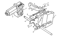
- the perspective view which shows the drive mechanism of a range switching shaft.
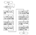
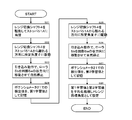
- the flowchart of control which performs learning of P range position.
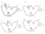
- the figure which shows the movement of a range switching shaft and a peripheral part when learning P range position.
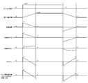
- the time chart at the time of control which learns a P range position.
- the time chart which shows the change of each value at the time of the control which performs a gear shift between P range and notP range.
- FIG. 1 is a system configuration diagram of a range switching device for an automatic transmission according to an embodiment.
- a motor 2 (actuator) for driving a range switching valve 6 described later is attached to an automatic transmission 1 mounted on a vehicle.
- a reduction gear mechanism 3 is provided on the output shaft of the motor 2, and the range switching shaft 4 is driven to rotate via the reduction gear mechanism 3.
- a predetermined play amount is provided in the rotation direction at a connecting portion by spline engagement or the like between the final stage of the reduction gear mechanism 3 and the range switching shaft 4.
- a detent mechanism 5 for positioning the range switching shaft 4 at an angle corresponding to each of a plurality of ranges is attached to the range switching shaft 4.
- the detent mechanism 5 is configured as shown in FIG.
- the detent lever 5A is fixed to the range switching shaft 4 and rotates integrally.
- the detent spring 5B supports a roller 5b that engages with a recess 5a formed on the periphery of the detent lever 5A corresponding to each range, and presses and biases the roller 5b toward the recess 5a.
- the detent mechanism 5 is configured so that the range switching shaft 4 is converted into the P range (parking range), R range (reverse range), N range (neutral range), D range (drive range), 2 ranges, 1 range. Position at an angle corresponding to any of the above.
- Stoppers 51A and 51B for restricting the operating range of the detent lever 5A are disposed on both sides in the rotational direction of the detent lever 5A.
- the rotational movement of the range switching shaft 4 is converted into the axial movement of the range switching valve 6 by the engagement of the detent lever 5A and the range switching valve 6, and the range switching valve 6 is displaced in the axial direction within the valve body 7. By doing so, the opening and closing of the hydraulic port is switched, and the line pressure is delivered according to each shift range.
- a cam 9 is attached to the other end of the rod 8 whose one end is attached to the detent lever 5A, and the parking pole 10 supported so as to be swingable is driven to swing by sliding contact with the cam 9.
- the pawl 10a of the parking pole 10 meshes with the recess 11a of the parking gear 11, and the parking gear 11 is fixed.
- the range switching shaft 4 is provided with a potentiometer 21 that continuously detects the angle of the range switching shaft 4, while an inhibitor switch 22 that detects which of the ranges the automatic transmission 1 is switched to. Is provided.
- a range select switch 23 that is operated by the driver is provided. Signals from the potentiometer 21, the inhibitor switch 22 and the range select switch 23 are input to an A / T control unit (A / TC / U) 24.
- the A / T control unit 24 drives and controls the motor 2 in response to a range switching request determined from the range select switch 23.
- the range switching control will be described later.
- the A / T control unit 24 has a function of setting a position corresponding to each range (target angle for each range) by learning in order to compensate for a shift in detection angle by the potentiometer 21. Will be described with reference to the flowchart of FIG.
- step S11 it is determined whether a learning condition is satisfied.
- the learning condition is set so that learning is performed in a vehicle stationary state that does not affect vehicle travel. For example, it is preferable that the vehicle is stopped and that the parking brake is used. Further, learning may be performed (included as a learning condition) before the product is shipped from the factory.
- step 12 the detent lever 5A is driven from the current position (P range position) toward the one stopper 51A and is brought into contact with the stopper 51A (see the dotted line in FIG. 4A).
- the stopper 51A Even in a state where the detent lever 5A is in contact with the stopper 51A, the stopper so that the pawl 10a of the parking pole 10 is engaged with the recess 11a of the parking gear 11 and the fixing (parking lock) of the parking gear 11 is maintained.
- the 51A position is set. Thereby, the 1st learning value mentioned later can be acquired in the state of vehicles in which parking lock was maintained.
- step 13 the range switching shaft 4 is driven at a predetermined angle ⁇ 1 in a direction away from the stopper 51A from the position (limit position) where the detent lever 5A is in contact with the stopper 51A.
- the roller 5b of the detent spring 5B reaches a position where the roller 5b rides a predetermined amount on the wall opposite to the stopper 51A from the valley of the recess 5a corresponding to the P range (see the solid line in FIG. 4A).
- step 14 the driving of the range switching shaft 4 is stopped.
- the retracting operation of the detent mechanism 5 by the elastic biasing force of the detent spring 5B causes the roller 5b to move toward the valley of the recess 5a from the position where the roller 5b rides on the wall on the side opposite to the stopper 51A and naturally stops (see FIG. 4 (B)).
- the predetermined angle ⁇ 1 is set to be within an effective range in which the pull-in operation occurs when the predetermined angle ⁇ 1 is driven and stopped.
- step 15 the angle of the range switching shaft 4 detected by the potentiometer 21 in the state where the roller 5 b moves from the side away from the stopper 51 A toward the valley of the recess 5 a and naturally stops, as described above. Is stored as the first learning value of the position corresponding to (P range target angle).
- step 16 the detent lever 5A is driven by a predetermined angle ⁇ 2 in the direction away from the stopper 51A from the above state.
- the roller 5b reaches a position where the roller 5b rides a predetermined amount on the wall on the stopper 51A side from the valley of the recess 5a corresponding to the P range (see FIG. 4C).
- step 17 the driving of the range switching shaft 4 is stopped.
- the retracting operation of the detent mechanism 5 by the elastic biasing force of the detent spring 5B causes the roller 5b to move toward the valley of the recess 5a from the position where the roller 5b rides on the stopper 51A side wall (FIG. 4 ( D)).
- the predetermined angle ⁇ 2 is set so as to be within an effective range in which the pull-in operation occurs when the predetermined angle ⁇ 2 is driven and stopped. Even when the detent lever 5A is driven at a predetermined angle ⁇ 2 away from the stopper 51A, the pawl 10a of the parking pole 10 is engaged with the recess 11a of the parking gear 11, and the parking gear 11 is fixed (parking locked). It is desirable to set the predetermined angle ⁇ 2 as described above and acquire a second learning value described later in a more stable vehicle stationary state.
- step 18 as described above, the roller 5b moves from the side close to the stopper 51A toward the valley of the recess 5a and naturally stops, and the angle of the range switching shaft 4 detected by the potentiometer 21 is changed to the P range. It is stored as a second learning value for the target angle.
- step S19 the target angle learned in the P range is determined based on the first learning value and the second learning value. For example, a value obtained by averaging the first learning value and the second learning value is set as the P range target angle.
- the predetermined angle ⁇ 1 to the position where the retracting operation is performed is set with reference to the position where the detent lever 5A is in contact with the stopper 51A.
- the predetermined angle ⁇ 1 can be accurately set, and the deviation angle between the first learning value obtained by the pull-in operation and the true target angle can be reduced.
- the first learning value may be set as the learning value of the final target angle.
- the potentiometer 21 is arranged so as to directly detect the angle of the range switching shaft 4, a highly accurate learning value can be obtained without being affected by the play amount in the transmission path from the motor 2 to the detent lever 5A. You can get it.
- the second learning value is acquired by the pull-in operation from the opposite direction to the first learning value, based on the two learning values by the pull-in operation from these different directions, The corresponding position (target angle) of the P range with higher accuracy can be set.
- a predetermined play amount is provided in the power transmission path between the motor 2 and the range switching shaft positioned at an angle corresponding to each range by the detent mechanism.
- the potentiometer 21 is often attached to the output shaft on the motor 2 side. In that case, the detected angle when the range switching shaft 4 is rotated in one direction is detected as a value that is larger by the amount of play than when there is no play, and the detected angle when rotated in the reverse direction is greater than that when there is no play. It will be detected as a smaller value.
- the first learning value obtained by the pull-in operation from the stopper 51A side is detected as a value smaller by the play amount, and obtained by the pull-in operation from the opposite side to the stopper 51A.
- the second learning value is detected as a value that is larger by the play amount, the influence of the play amount can be offset by averaging the first learning value and the second learning value, and the target angle can be accurately obtained. Can be set.
- the influence of friction can be offset and the target angle can be set with higher accuracy.
- a method is also known in which the valley position of the recess is obtained by calculating the angular velocity and angular acceleration of the detected angle value, but a high-functional CPU is required to accurately calculate the angular velocity and angular acceleration.
- such a complicated calculation is not required, and a highly accurate shift range position can be set using a relatively low-cost CPU.
- FIG. 6 shows a time chart during control of switching from the P range to another range (notP range) and then switching from the notP range to the P range.
- a three-phase alternating current obtained by converting a direct current from a battery into a three-phase inverter is used as the motor 2, and the PWM duty output to the three-phase inverter is calculated from the peak voltage (absolute value) and controlled.
- the peak voltage manipulated variable VPEAK is a positive value.
- VPEAK is negative. Set to value.
- the P and I minutes in PI control are determined according to the deviation between the current position (actual angle) of the range switching shaft 4 detected by the potentiometer 21 and the notP range position after the range is switched. Are set respectively.
- a feed forward gain (FF gain) is set according to the current position of the range switching shaft 4.
- the FF gain has a characteristic of gradually decreasing from a positive predetermined value corresponding to the P range position to a negative predetermined value corresponding to the notP range position.
- the peak voltage manipulated variable VPEAK is set by converting a value obtained by adding the P, I and FF gains.
- the position corresponding to the shift range (the rotation angle of the range switching shaft 4) is learned and corrected, whereby the corrected range corresponding position (target angle) and the range switching shaft 4 detected by the potentiometer 21 are detected. Based on the current position, the position can be quickly and accurately positioned (the roller is positioned at the valley of the recess) at the range position after switching.
- the learning of the notP range position will be described with reference to the flowchart of FIG. 7 after the learning of the P range position shown in FIG. 3.
- the learning may be performed independently after newly determining whether the learning condition is satisfied.
- step S21 the detent lever 5A is driven from the current P range position toward the stopper 51A and is brought into contact with the stopper 51A.
- step S22 the range switching shaft 4 is driven at a predetermined angle ⁇ 11 in a direction away from the stopper 51A from the position where the detent lever 5A is in contact with the stopper 51A.
- the roller 5b of the detent spring 5B reaches a position where the roller 5b rides a predetermined amount on the wall opposite to the stopper 51A from the valley of the recess 5a corresponding to the notP range.
- step 23 the driving of the range switching shaft 4 is stopped. Thereby, the pulling operation of the detent mechanism 5 by the elastic urging force of the detent spring 5B moves the roller 5b from the position on the wall opposite to the stopper 51A toward the valley of the recess 5a corresponding to the notP range. Stop naturally.
- the predetermined angle ⁇ 11 is set so as to be within an effective range in which the pull-in operation occurs when the predetermined angle ⁇ 11 is driven and stopped.
- the range switching shaft detected by the potentiometer 21 in the natural stop state when the roller 5b moves from the side away from the stopper 51A toward the valley of the recess 5a and stops naturally as described above. 4 is stored as the first learning value of the position corresponding to the notP range (notP range target angle).
- step 25 the detent lever 5A is driven at a predetermined angle ⁇ 12 in a direction away from the stopper 51A from the above state.
- the roller 5b reaches a position where the roller 5b rides a predetermined amount on the wall on the stopper 51A side from the valley of the recess 5a corresponding to the notP range.
- step 26 the driving of the range switching shaft 4 is stopped.
- the retracting operation of the detent mechanism 5 by the elastic biasing force of the detent spring 5B causes the roller 5b to move toward the valley of the recess 5a from the position where the roller 5b rides on the wall on the stopper 51A side, and stops naturally.
- the predetermined angle ⁇ 12 is set to an effective range in which the pull-in operation occurs when the predetermined angle ⁇ 12 is driven and stopped.
- step 27 as described above, the roller 5b moves from the side close to the stopper 51A toward the valley of the recess 5a and naturally stops, and the angle of the range switching shaft 4 detected by the potentiometer 21 is changed to the P range. It is stored as a second learning value for the target angle.
- a target angle learned in the P range is determined based on the first learning value and the second learning value. For example, a value obtained by averaging the first learning value and the second learning value is set as the notP range target angle.
- a predetermined angle ⁇ 11 ′, ⁇ 12 ′ from the P range position after learning is set as a reference position to a position where the notP range position is pulled in is set, and the predetermined angles ⁇ 11 ′, You may make it drive by (theta) 12 '. In this way, it is not necessary to bring the detent lever 5A into contact with the stopper 51A, and the learning time can be shortened.
- the drive amount to the retracting operation position is smaller when the notP range position is far from the P range position and is brought into contact with the stopper 51B opposite to the stopper 51A. is there.
- the learning value corresponding to the range position or the detected value during learning shows an abnormal value, it is determined that some abnormality may have occurred, the drive of the motor 2 is stopped, and an alarm is issued. Is preferably output.
- the position where the natural stop is caused by the pulling-in operation can be changed by changing the magnitude of friction of the motor, the speed reduction mechanism, etc. in accordance with changes in the lubricating oil temperature, the cooling water temperature, and the like. Therefore, the set values of the predetermined angles ⁇ 1, ⁇ 2, ⁇ 11, ⁇ 12, ⁇ 11 ′, ⁇ 12 ′ are changed so that the natural stop position is as close as possible to the valley position of the recess according to the lubricating oil temperature, cooling water temperature, etc. May be set.
Landscapes
- Engineering & Computer Science (AREA)
- General Engineering & Computer Science (AREA)
- Mechanical Engineering (AREA)
- Gear-Shifting Mechanisms (AREA)
- Warehouses Or Storage Devices (AREA)
- Control Of Transmission Device (AREA)
Abstract
Description
アクチュエータと、該アクチュエータにより駆動され、変速機レンジに対応する位置に形成された凹部に係合されて位置決めされることにより、変速機のレンジを変更するディテント機構と、該ディテント機構を、その移動範囲の限界位置まで駆動してから該限界位置から離れる方向に所定量駆動し、該ディテント機構が前記凹部の谷に向かって移動し自然停止したときの位置を、変速機レンジに対応する位置として設定する制御部と、を含んで構成される。
アクチュエータによりディテント機構を駆動し、該ディテント機構を変速機レンジに対応する位置に形成された凹部に係合させて位置決めすることにより、変速機のレンジを変更する自動変速機のレンジ切換え方法であって、ディテント機構を、その移動範囲の限界位置まで駆動してから該限界位置から離れる方向に所定量駆動し、該ディテント機構が前記凹部の谷に向かって移動し自然停止したときの位置を、前記変速機レンジに対応する位置として設定する。
図1は、実施の形態における自動変速機のレンジ切換え装置のシステム構成図である。
図1において、車両に搭載される自動変速機1には、後述するレンジ切換バルブ6を駆動するためのモータ2(アクチュエータ)が取り付けられる。
尚、前記減速歯車機構3の最終段とレンジ切換シャフト4とのスプライン係合等による連結部には、回転方向に所定の遊び量が設けられている。
前記ディテント機構5は、図2に示すように構成されている。ディテントレバー5Aは、レンジ切換シャフト4に固定されて一体に回転する。ディテントスプリング5Bは、ディテントレバー5Aの周縁に各レンジに対応して形成される凹部5aに係合するローラ5bを支持すると共に、該ローラ5bを前記凹部5aに向けて押圧付勢する。
前記レンジ切換シャフト4の回転運動は、ディテントレバー5Aとレンジ切換バルブ6との係合によって、レンジ切換バルブ6の軸方向運動に変換され、レンジ切換バルブ6がバルブボディ7内で軸方向に変位することで、油圧ポートの開閉が切り換えられ、各シフトレンジに応じてライン圧を配送する。
前記ポテンショメータ21,インヒビタスイッチ22及びレンジセレクトスイッチ23からの信号は、A/Tコントロールユニット(A/T C/U)24に入力される。
ステップ12では、ディテントレバー5Aを現在の位置(Pレンジ位置)から一方のストッパ51Aに向けて駆動し、ストッパ51Aに当接させる(図4(A)の点線参照)。
ステップ15では、上記のようにローラ5bがストッパ51Aから離れた側から凹部5aの谷に向かって移動して自然停止した状態において、ポテンショメータ21で検出されたレンジ切換シャフト4の角度を、Pレンジに対応する位置(Pレンジ目標角度)の第1学習値として記憶する。
なお、ディテントレバー5Aをストッパ51Aから離れる方向に所定角度θ2駆動した状態でも、パーキングポール10の爪10aがパーキングギヤ11の凹部11aに噛み合って、パーキングギヤ11の固定(パーキングロック)は維持されるように所定角度θ2を設定し、より安定した車両静止状態で後述する第2学習値を取得することが望ましい。
なお、凹部の谷位置を角度検出値の角速度や角加速度を算出して求める方法も知られるが、角速度,角加速度を精度よく演算するため高機能のCPUが必要となる。これに対し、本実施形態では、このような複雑な演算が不要であり比較的低コストなCPUを用いて高精度な変速レンジ位置の設定を行うことができる。
本実施形態では、モータ2として例えばバッテリからの直流電流を3相インバータに変換した3相交流を用い、3相インバータに出力されるPWMデューティをピーク電圧(絶対値)から算出して制御する。また、レンジ切換シャフト4をPレンジからnotPレンジ位置に切り換えるときの回転方向では、ピーク電圧操作量VPEAKを正の値、notPレンジ位置からPレンジ位置に切り換えるときの回転方向では、VPEAKを負の値に設定する。
以下、図3に示したPレンジ位置の学習終了後、notPレンジ位置の学習を行う場合について図7のフローチャートに従って説明するが、例えば、停車毎に学習するレンジを変更する等、notPレンジ位置の学習を新たに学習条件成立の判断を行った後、単独で行うようにしてもよい。
なお、notPレンジ位置の学習を行う場合は、学習成立条件としてパーキングブレーキの使用を含めることが安定した車両静止状態を確保できるので好ましい。
ステップS22では、ディテントレバー5Aをストッパ51Aに当接させた位置から、レンジ切換シャフト4を、ストッパ51Aから離れる方向に所定角度θ11駆動する。これにより、ディテントスプリング5Bのローラ5bがnotPレンジに対応する凹部5aの谷からストッパ51Aと反対側の壁に所定量乗り上げた位置に達する。
ステップ24では、上記のようにローラ5bがストッパ51Aから離れた側から凹部5aの谷に向かって移動して自然停止した状態で、前記自然停止した状態において、ポテンショメータ21で検出されたレンジ切換シャフト4の角度を、notPレンジに対応する位置(notPレンジ目標角度)の第1学習値として記憶する。
ステップ27では、上記のように、ローラ5bがストッパ51Aに近い側から凹部5aの谷に向かって移動して自然停止した状態で、ポテンショメータ21で検出されたレンジ切換シャフト4の角度を、Pレンジ目標角度の第2学習値として記憶する。
Claims (15)
- 自動変速機のレンジ切換え装置であって、
アクチュエータと、
前記アクチュエータにより駆動され、変速機レンジに対応する位置に形成された凹部に係合されて位置決めされることにより、変速機のレンジを変更するディテント機構と、
前記ディテント機構を、その移動範囲の限界位置まで駆動してから該限界位置から離れる方向に所定量駆動し、該ディテント機構が前記凹部の谷に向かって移動し自然停止したときの位置を、前記変速機レンジに対応する位置の目標値として設定する制御部と、
を含んで構成される、自動変速機のレンジ切換え装置。 - 前記所定量は、前記限界位置から特定される、前記凹部への引き込み動作の有効範囲に基づいて設定される、請求項1に記載の自動変速機のレンジ切換え装置。
- 前記アクチュエータと、前記ディテント機構との間の動力伝達経路に所定の遊び量を有する、請求項1に記載の自動変速機のレンジ切換え装置。
- 前記制御部は、前記ディテント機構を相異なる方向から前記凹部の谷に向かって移動し自然停止したときの位置をそれぞれ学習し、各学習結果に基づいて前記目標値を設定する、請求項1に記載の自動変速機のレンジ切換え装置。
- 前記制御部は、前記各学習結果を平均化処理することにより、前記目標値を設定する、請求項4に記載の自動変速機のレンジ切換え装置。
- 前記制御部は、当該自動変速機を搭載した車両の停止時に、前記目標値を設定する、請求項1に記載の自動変速機のレンジ切換え装置。
- 変速レンジをPレンジとしたときに、パーキングロックが作用する機構を備え、
前記制御部は、前記パーキングロックが有効に作用している状態で、Pレンジに対応する位置の前記目標値を設定する、請求項6に記載の自動変速機のレンジ切換え装置。 - 前記ディテント機構は、相異なる移動方向に対して設定された一対の限界位置によって移動範囲が規制され、
前記制御部は、前記一対の限界位置への駆動を行って、複数の前記変速機レンジに対応する位置の前記目標値を設定する、請求項1に記載の自動変速機のレンジ切換え装置。 - 前記制御部は、前記変速機レンジに対応する位置の設定が終了した変速レンジとは別の変速レンジに対応する位置の前記目標値を設定をするとき、前記設定が終了した変速レンジから離れる方向に所定量駆動し、ディテント機構が前記別の変速レンジに対応する凹部の谷に向かって移動し自然停止したときの位置を、該別の変速機レンジに対応する位置の目標値として設定する、請求項1に記載の自動変速機のレンジ切換え装置。
- アクチュエータによりディテント機構を駆動し、該ディテント機構を変速機レンジに対応する位置に形成された凹部に係合させて位置決めすることにより、変速機のレンジを変更する自動変速機のレンジ切換え方法であって、
前記ディテント機構を、その移動範囲の限界位置まで駆動してから該限界位置から離れる方向に所定量駆動し、
該ディテント機構が前記凹部の谷に向かって移動し自然停止したときの位置を、前記変速機レンジに対応する位置の目標値として設定する、自動変速機のレンジ切換え方法。 - 前記ディテント機構を相異なる方向から前記凹部の谷に向かって移動し自然停止したときの位置をそれぞれ学習し、各学習結果に基づいて前記目標値を設定する、請求項10に記載の自動変速機のレンジ切換え方法。
- 前記各学習結果を平均化処理することにより、前記目標値を設定する、請求項11に記載の自動変速機のレンジ切換え方法。
- 当該自動変速機を搭載した車両の停止時に、前記目標値を設定する、請求項10に記載の自動変速機のレンジ切換え方法。
- 前記ディテント機構は、相異なる移動方向に対して設定された一対の限界位置によって移動範囲が規制され、
前記一対の限界位置への駆動を行って、複数の前記変速機レンジに対応する位置の前記目標値を設定する、請求項10に記載の自動変速機のレンジ切換え方法。 - 前記変速機レンジに対応する位置の設定が終了した変速レンジとは別の変速レンジに対応する位置の前記目標値を設定をするとき、前記設定が終了した変速レンジから離れる方向に所定量駆動し、ディテント機構が前記別の変速レンジに対応する凹部の谷に向かって移動し自然停止したときの位置を、該別の変速機レンジに対応する位置の前記目標値として設定する、請求項10に記載の自動変速機のレンジ切換え方法。
Priority Applications (3)
| Application Number | Priority Date | Filing Date | Title |
|---|---|---|---|
| CN201480018006.XA CN105051428B (zh) | 2013-03-26 | 2014-03-12 | 自动变速器的档切换装置及方法 |
| DE112014001667.5T DE112014001667B4 (de) | 2013-03-26 | 2014-03-12 | Vorrichtung und Verfahren zum Schalten des Bereichs eines Automatikgetriebes |
| US14/779,144 US9581238B2 (en) | 2013-03-26 | 2014-03-12 | Device and method for switching range of automatic transmission |
Applications Claiming Priority (2)
| Application Number | Priority Date | Filing Date | Title |
|---|---|---|---|
| JP2013063342A JP6062298B2 (ja) | 2013-03-26 | 2013-03-26 | 自動変速機のレンジ切換え装置 |
| JP2013-063342 | 2013-03-26 |
Publications (1)
| Publication Number | Publication Date |
|---|---|
| WO2014156660A1 true WO2014156660A1 (ja) | 2014-10-02 |
Family
ID=51623643
Family Applications (1)
| Application Number | Title | Priority Date | Filing Date |
|---|---|---|---|
| PCT/JP2014/056529 Ceased WO2014156660A1 (ja) | 2013-03-26 | 2014-03-12 | 自動変速機のレンジ切換え装置及び方法 |
Country Status (5)
| Country | Link |
|---|---|
| US (1) | US9581238B2 (ja) |
| JP (1) | JP6062298B2 (ja) |
| CN (1) | CN105051428B (ja) |
| DE (1) | DE112014001667B4 (ja) |
| WO (1) | WO2014156660A1 (ja) |
Families Citing this family (15)
| Publication number | Priority date | Publication date | Assignee | Title |
|---|---|---|---|---|
| JP2016145601A (ja) * | 2015-02-06 | 2016-08-12 | 株式会社デンソー | シフトバイワイヤ制御装置 |
| JP6443189B2 (ja) * | 2015-04-02 | 2018-12-26 | 株式会社デンソー | シフトレンジ切替装置 |
| JP6459936B2 (ja) * | 2015-12-01 | 2019-01-30 | 株式会社デンソー | レンジ切り換え装置 |
| CN106402374B (zh) * | 2016-09-20 | 2019-01-04 | 联合汽车电子有限公司 | 离合器控制方法 |
| JP6705428B2 (ja) | 2017-06-16 | 2020-06-03 | 株式会社デンソー | シフトレンジ制御装置 |
| KR102435199B1 (ko) * | 2017-12-30 | 2022-08-23 | 에스엘 주식회사 | 변속기 제어 장치 및 제어 방법 |
| JP6950545B2 (ja) * | 2018-01-19 | 2021-10-13 | 株式会社デンソー | シフトレンジ制御装置 |
| FR3088401B1 (fr) * | 2018-11-08 | 2020-10-23 | Renault Sas | Procede et dispositif de controle de l’engagement d’un doigt de parking |
| JP7271835B2 (ja) * | 2019-03-29 | 2023-05-12 | ニデックパワートレインシステムズ株式会社 | 電動アクチュエータ、およびアクチュエータ装置 |
| CN112594374B (zh) * | 2020-12-08 | 2022-02-25 | 安徽江淮汽车集团股份有限公司 | 车辆的p挡角度学习方法、车辆及计算机可读存储介质 |
| KR102630700B1 (ko) * | 2021-03-29 | 2024-01-29 | 주식회사 현대케피코 | 시프트 바이 와이어 시스템의 변속 위치 학습 방법 및 장치 |
| JP7548141B2 (ja) * | 2021-06-24 | 2024-09-10 | トヨタ自動車株式会社 | 車両の制御装置 |
| KR102673275B1 (ko) | 2021-11-05 | 2024-06-05 | 주식회사 현대케피코 | Sbw 시스템의 이상 진단 시스템 및 이를 이용한 이상 진단 방법 |
| KR102673278B1 (ko) | 2021-12-24 | 2024-06-05 | 주식회사 현대케피코 | Sbw 시스템의 초기 위치 학습 시스템 및 이를 이용한 초기 위치 학습 방법 |
| CN115773363B (zh) * | 2022-11-17 | 2024-09-17 | 中国第一汽车股份有限公司 | 一种基于电子换挡的挡位自学习方法、装置、车辆及介质 |
Citations (5)
| Publication number | Priority date | Publication date | Assignee | Title |
|---|---|---|---|---|
| JP2002048230A (ja) * | 2000-08-03 | 2002-02-15 | Niles Parts Co Ltd | 自動変速機の調整システム |
| JP2006136035A (ja) * | 2004-11-02 | 2006-05-25 | Denso Corp | モータ制御装置 |
| JP2006260435A (ja) * | 2005-03-18 | 2006-09-28 | Jatco Ltd | 自動変速機におけるマニュアルプレートの回動範囲規制構造 |
| JP2010112524A (ja) * | 2008-11-10 | 2010-05-20 | Suzuki Motor Corp | シフトセレクトシステム |
| JP2012107656A (ja) * | 2010-11-15 | 2012-06-07 | Denso Corp | シフトバイワイヤシステム |
Family Cites Families (8)
| Publication number | Priority date | Publication date | Assignee | Title |
|---|---|---|---|---|
| US7370547B2 (en) * | 2003-04-04 | 2008-05-13 | Toyota Jidosha Kabushiki Kaisha | Shift control system, shift control method and shift switching device |
| JP4248290B2 (ja) * | 2003-04-04 | 2009-04-02 | 株式会社デンソー | シフト制御システムおよびシフト制御方法 |
| DE102005025349A1 (de) | 2005-05-31 | 2006-12-07 | Schulz, Rolf A., Dipl.-Kaufm. | Inhalator-Halter |
| JP2009177965A (ja) * | 2008-01-25 | 2009-08-06 | Denso Corp | モータ制御装置 |
| JP5344087B2 (ja) * | 2010-04-15 | 2013-11-20 | トヨタ自動車株式会社 | 自動変速機のシフトレンジ切替装置 |
| JP5287788B2 (ja) * | 2010-04-27 | 2013-09-11 | トヨタ自動車株式会社 | 自動変速機のレンジ切り替え装置 |
| JP2012013216A (ja) * | 2010-07-05 | 2012-01-19 | Toyota Motor Corp | 車両用自動変速機のシフト切換制御装置 |
| DE102011086207B4 (de) | 2010-11-15 | 2021-02-04 | Denso Corporation | Shift-by-wire-system |
-
2013
- 2013-03-26 JP JP2013063342A patent/JP6062298B2/ja not_active Expired - Fee Related
-
2014
- 2014-03-12 DE DE112014001667.5T patent/DE112014001667B4/de not_active Expired - Fee Related
- 2014-03-12 CN CN201480018006.XA patent/CN105051428B/zh not_active Expired - Fee Related
- 2014-03-12 WO PCT/JP2014/056529 patent/WO2014156660A1/ja not_active Ceased
- 2014-03-12 US US14/779,144 patent/US9581238B2/en not_active Expired - Fee Related
Patent Citations (5)
| Publication number | Priority date | Publication date | Assignee | Title |
|---|---|---|---|---|
| JP2002048230A (ja) * | 2000-08-03 | 2002-02-15 | Niles Parts Co Ltd | 自動変速機の調整システム |
| JP2006136035A (ja) * | 2004-11-02 | 2006-05-25 | Denso Corp | モータ制御装置 |
| JP2006260435A (ja) * | 2005-03-18 | 2006-09-28 | Jatco Ltd | 自動変速機におけるマニュアルプレートの回動範囲規制構造 |
| JP2010112524A (ja) * | 2008-11-10 | 2010-05-20 | Suzuki Motor Corp | シフトセレクトシステム |
| JP2012107656A (ja) * | 2010-11-15 | 2012-06-07 | Denso Corp | シフトバイワイヤシステム |
Also Published As
| Publication number | Publication date |
|---|---|
| DE112014001667T5 (de) | 2015-12-24 |
| CN105051428A (zh) | 2015-11-11 |
| JP6062298B2 (ja) | 2017-01-18 |
| CN105051428B (zh) | 2016-12-14 |
| US9581238B2 (en) | 2017-02-28 |
| US20160053885A1 (en) | 2016-02-25 |
| DE112014001667B4 (de) | 2018-04-05 |
| JP2014190349A (ja) | 2014-10-06 |
Similar Documents
| Publication | Publication Date | Title |
|---|---|---|
| JP6062298B2 (ja) | 自動変速機のレンジ切換え装置 | |
| US10690243B2 (en) | Range switching device for automatic transmission and switching method therefor | |
| US10794479B2 (en) | Shift range control device | |
| US10781918B2 (en) | Shift range control device | |
| RU2588699C9 (ru) | Способ калибровки датчика выбранной передачи и система датчиков выбранной передачи | |
| JP2015145711A (ja) | シフトレンジ切り替え装置 | |
| US11708896B2 (en) | Shift range control device | |
| WO2018190284A1 (ja) | シフトレンジ制御装置 | |
| JP4672066B2 (ja) | 自動変速機の制御装置 | |
| US11624438B2 (en) | Shift range control device | |
| WO2019049993A1 (ja) | シフトレンジ制御装置 | |
| US11313458B2 (en) | Shift range control apparatus | |
| JP7017940B2 (ja) | 電動式アクチュエータおよび電動ブレーキ装置 | |
| US11162580B2 (en) | Shift range control device | |
| WO2019131331A1 (ja) | シフトレンジ制御装置 | |
| US11879407B1 (en) | Throttle control system and method of operation | |
| US11614163B2 (en) | Motor control method and device for shift-by-wire system | |
| JP4572858B2 (ja) | シフトバイワイヤ式レンジ切換え装置 | |
| JP4606488B2 (ja) | クラッチの制御装置 | |
| WO2022270382A1 (ja) | 電動式直動アクチュエータ | |
| JP2007139101A (ja) | レンジ切換制御装置及びレンジ切換制御方法 | |
| JP2009127449A (ja) | 可変動弁装置、アクチュエータの制御装置、及び回転角センサ | |
| JP2007139104A (ja) | レンジ切換制御システム及びレンジ切換制御方法 | |
| KR20050088861A (ko) | 예측 pid 제어기를 이용한 자동차 스로틀 밸브 엑츄에이터 제어 | |
| JP2004100733A (ja) | 自動変速機のレンジ切換え装置 |
Legal Events
| Date | Code | Title | Description |
|---|---|---|---|
| WWE | Wipo information: entry into national phase |
Ref document number: 201480018006.X Country of ref document: CN |
|
| 121 | Ep: the epo has been informed by wipo that ep was designated in this application |
Ref document number: 14773984 Country of ref document: EP Kind code of ref document: A1 |
|
| DPE1 | Request for preliminary examination filed after expiration of 19th month from priority date (pct application filed from 20040101) | ||
| WWE | Wipo information: entry into national phase |
Ref document number: 14779144 Country of ref document: US |
|
| WWE | Wipo information: entry into national phase |
Ref document number: 1120140016675 Country of ref document: DE Ref document number: 112014001667 Country of ref document: DE |
|
| 122 | Ep: pct application non-entry in european phase |
Ref document number: 14773984 Country of ref document: EP Kind code of ref document: A1 |