WO2014156050A1 - Three-dimensional image output device and background image generation device - Google Patents
Three-dimensional image output device and background image generation device Download PDFInfo
- Publication number
- WO2014156050A1 WO2014156050A1 PCT/JP2014/001531 JP2014001531W WO2014156050A1 WO 2014156050 A1 WO2014156050 A1 WO 2014156050A1 JP 2014001531 W JP2014001531 W JP 2014001531W WO 2014156050 A1 WO2014156050 A1 WO 2014156050A1
- Authority
- WO
- WIPO (PCT)
- Prior art keywords
- image
- dimensional
- background
- background image
- drawn
- Prior art date
Links
Images


Classifications
-
- G—PHYSICS
- G06—COMPUTING; CALCULATING OR COUNTING
- G06T—IMAGE DATA PROCESSING OR GENERATION, IN GENERAL
- G06T11/00—2D [Two Dimensional] image generation
- G06T11/60—Editing figures and text; Combining figures or text
-
- G—PHYSICS
- G06—COMPUTING; CALCULATING OR COUNTING
- G06T—IMAGE DATA PROCESSING OR GENERATION, IN GENERAL
- G06T17/00—Three dimensional [3D] modelling, e.g. data description of 3D objects
- G06T17/05—Geographic models
-
- G—PHYSICS
- G01—MEASURING; TESTING
- G01C—MEASURING DISTANCES, LEVELS OR BEARINGS; SURVEYING; NAVIGATION; GYROSCOPIC INSTRUMENTS; PHOTOGRAMMETRY OR VIDEOGRAMMETRY
- G01C21/00—Navigation; Navigational instruments not provided for in groups G01C1/00 - G01C19/00
- G01C21/26—Navigation; Navigational instruments not provided for in groups G01C1/00 - G01C19/00 specially adapted for navigation in a road network
- G01C21/34—Route searching; Route guidance
- G01C21/36—Input/output arrangements for on-board computers
- G01C21/3626—Details of the output of route guidance instructions
- G01C21/3635—Guidance using 3D or perspective road maps
- G01C21/3638—Guidance using 3D or perspective road maps including 3D objects and buildings
-
- G—PHYSICS
- G09—EDUCATION; CRYPTOGRAPHY; DISPLAY; ADVERTISING; SEALS
- G09B—EDUCATIONAL OR DEMONSTRATION APPLIANCES; APPLIANCES FOR TEACHING, OR COMMUNICATING WITH, THE BLIND, DEAF OR MUTE; MODELS; PLANETARIA; GLOBES; MAPS; DIAGRAMS
- G09B29/00—Maps; Plans; Charts; Diagrams, e.g. route diagram
- G09B29/003—Maps
- G09B29/005—Map projections or methods associated specifically therewith
-
- H—ELECTRICITY
- H04—ELECTRIC COMMUNICATION TECHNIQUE
- H04N—PICTORIAL COMMUNICATION, e.g. TELEVISION
- H04N5/00—Details of television systems
- H04N5/222—Studio circuitry; Studio devices; Studio equipment
- H04N5/262—Studio circuits, e.g. for mixing, switching-over, change of character of image, other special effects ; Cameras specially adapted for the electronic generation of special effects
- H04N5/272—Means for inserting a foreground image in a background image, i.e. inlay, outlay
-
- G—PHYSICS
- G06—COMPUTING; CALCULATING OR COUNTING
- G06F—ELECTRIC DIGITAL DATA PROCESSING
- G06F3/00—Input arrangements for transferring data to be processed into a form capable of being handled by the computer; Output arrangements for transferring data from processing unit to output unit, e.g. interface arrangements
- G06F3/01—Input arrangements or combined input and output arrangements for interaction between user and computer
- G06F3/011—Arrangements for interaction with the human body, e.g. for user immersion in virtual reality
- G06F3/013—Eye tracking input arrangements
-
- G—PHYSICS
- G06—COMPUTING; CALCULATING OR COUNTING
- G06T—IMAGE DATA PROCESSING OR GENERATION, IN GENERAL
- G06T2215/00—Indexing scheme for image rendering
- G06T2215/16—Using real world measurements to influence rendering
-
- G—PHYSICS
- G06—COMPUTING; CALCULATING OR COUNTING
- G06T—IMAGE DATA PROCESSING OR GENERATION, IN GENERAL
- G06T2219/00—Indexing scheme for manipulating 3D models or images for computer graphics
- G06T2219/20—Indexing scheme for editing of 3D models
- G06T2219/2012—Colour editing, changing, or manipulating; Use of colour codes
Definitions
- the present invention relates to a technology of outputting a three-dimensional image, in which a background image is superimposed on an image expressing an object three-dimensionally.
- Three-dimensional maps that three-dimensionally express features such as buildings and roads have become used widely. Bird's eye views that look down features in a wide area obliquely from above have also recently become popular. Such a three-dimensional map is often drawn by perspective projection of a three-dimensional model placed on the flat ground surface.
- a variety of techniques have been proposed to display a distant view image such as the mountains, the sky and the clouds, with respect to such a three-dimensional image.
- a technique has also been used to superimpose a foreground image layer provided separately from an image drawn by perspective projection on the image.
- Patent Literature 1 draws a background image located behind a display area of roads and buildings, based on a distant view pattern provided in advance with respect to each orientation area.
- the three-dimensional map is displayed in various display scales, so that drawing according to the display scale is desired.
- a bird's eye view in which the horizon is expressed by a curved line may be obtained by application of a sphere model that expresses the shape of the earth as a sphere or by application of an earth ellipsoid model that expressed the shape of the earth as an earth ellipsoid.
- Such display needs to provide both a three-dimensional model for the flat ground surface and a three-dimensional model for the spherical ground surface or undesirably increases the processing load of operations to express the horizon by a curved line.
- the three-dimensional map may accordingly have a problem of remarkably increasing the data volume or the processing load in an attempt to improve the reality of the drawn background as described above. This problem is not limited to the three-dimensional map but is commonly found in the configuration of outputting a three-dimensional image.
- an object of the invention is to improve the reality of a drawn background while suppressing an increase in processing load in output of a three-dimensional image in which an object is drawn three-dimensionally, along with a background image.
- a three-dimensional image output device that outputs a three-dimensional image in which an object is drawn three-dimensionally.
- the three-dimensional image output device comprises: a three-dimensional model storage that stores a three-dimensional model representing a three-dimensional shape of the object; a projecting section that uses the three-dimensional model and generates a three-dimensional object image that expresses the object three-dimensionally; a background layer generating section that generates a background layer, in which a background image of the three-dimensional image is drawn to have a transparent portion and an opaque portion; and an image output controller that superimposes the background layer on a front surface of the three-dimensional object image to generate the three-dimensional image and outputs the three-dimensional image.
- At least one of a generating condition of the three-dimensional object image and a generating condition of the background layer is adjusted to cause the opaque portion to cover and hide part of the three-dimensional object image.
- the three-dimensional image may be output in various aspects, for example, displayed on a display unit and output as a printed matter.
- the three-dimensional image output device of the invention superimposes the background layer on the front surface of the three-dimensional object image.
- the background layer is originally a layer showing the background of a three-dimensional object image, i.e., a layer showing an image to be drawn at a greater distance than the three-dimensional object image.
- the background layer should thus be fundamentally located behind the three-dimensional object image.
- the invention dares to locate the background layer on the front surface of the three-dimensional object image.
- the background layer has the transparent portion, so that the three-dimensional object image is visible even when the background layer is located on the front surface of the three-dimensional object image.
- the background layer has the opaque portion to cover and hide part of the three-dimensional object image.
- Covering and hiding part of the three-dimensional object image with the opaque portion enables an image that is fundamentally implemented using complicated coordinate conversion or a special three-dimensional model to be expressed by a pseudo-image. Accordingly the invention enables a variety of backgrounds to be output with the improved reality, while suppressing increases in data volume and processing load in the process of outputting a three-dimensional image, in which an object is drawn three-dimensionally, along with a background image.
- the background layer may be generated by any of various methods.
- One available method may provide in advance background image data including a transparent portion and an opaque portion and draw the background image data on a two-dimensional layer provided separately from a projection plane of a three-dimensional object image to generate a background layer.
- Another available method may provide background data representing a background image, define a transparent portion and an opaque portion on a two-dimensional layer according to a drawn three-dimensional object image, and draw the opaque portion using the background data to generate a background layer.
- the three-dimensional model may be map data representing three-dimensional shapes of ground surface and features, and the three-dimensional image may be a three-dimensional map that expresses a geographical shape three-dimensionally.
- the three-dimensional map has an extremely large volume of data and needs to output various backgrounds in order to improve the reality.
- the three-dimensional map may additionally need to be displayed in real time or need to be displayed on a terminal of relatively low throughput, such as a handheld terminal.
- the invention is thus especially effective for the three-dimensional map to draw various backgrounds while suppressing increases in data volume and processing load.
- the background image may have the opaque portion, which shows the stratosphere of the earth, in an upper part of the background image and the transparent portion in a lower part of the background image, and a boundary between the transparent portion and the opaque portion is expressed by a circular arc or an elliptical arc connecting a left side and a right side of the background image.
- the projecting section may generate the three-dimensional object image having the part covered and hidden by the opaque portion from a viewpoint position where a horizon is to be recognized as a curved line.
- the background image may include a transparent gradation area that gradually changes transmittance of an image on a boundary between the transparent portion and the opaque portion.
- the width of the transparent gradation area may be changed, for example, according to the scale of the three-dimensional map, in such a range that provides the above visual effect. In the transparent gradation area, not only the transmittance but the color of the background image may be changed.
- a background image generation device that generates a background image which is to be superimposed in output of a three-dimensional image in which an object is drawn three-dimensionally, wherein the background image includes a transparent portion that causes an image to be transmitted and an opaque portion that does not cause an image to be transmitted.
- the background image generation device comprises: an object drawing range input section that inputs information specifying an object drawing range in which the object is drawn, in a three-dimensional object image that expresses the object three-dimensionally and is generated as an image, on which the background image is to be superimposed; a background specifying information input section that inputs background specifying information specifying a content of a background of the three-dimensional object image in the three-dimensional image; and a background image generator that generates the background image including the opaque portion configured to cause part of the object drawing range to be covered and hidden by the specified background and a residual area of the opaque portion specified as the transparent portion.
- the background layer generated by the three-dimensional image output device of the invention may be generated by using background image data provided in advance to have a transparent portion and an opaque portion or may be newly generated as a background image having a transparent portion and an opaque portion according to the three-dimensional object image.
- the background image generation device of the invention may be configured as a separate device from the three-dimensional image output device and may be used as the device to generate the background image data of the former embodiment in advance.
- the background image generation device may alternatively be configured to be operable in cooperation with the three-dimensional image output device and may be used as the device to generate the background image of the latter embodiment according to the three-dimensional object image at the time of output.
- the background image generation device of the invention appropriately and flexibly generates the background image used in the three-dimensional image output device described above, based on the object drawing range in the three-dimensional object image and the background specifying information.
- the “content of the background” means the type of an image to be drawn as the background, for example, the stratosphere or under the sea.
- the content of the background may be specified, for example, by selection among menu options provided in advance.
- a method of generating the background image of the specified content may store original background image data, in which the entire image is specified as an opaque portion, and replace part of this original background image data with a transparent portion.
- the background image may be generated by drawing the image of an opaque portion in a color and a shape according to the specified content.
- the invention may not necessarily include all the features described above but may be configured appropriately with partial omission or by combination of these features.
- the invention is not limited to the configurations of the three-dimensional image output device and the background image generation device described above but may be configured as any of various other aspects: for example, a three-dimensional image output method, a background image generation method, computer programs that implement the functions of these methods; non-transitory storage media in which such computer programs are stored; and data signals that include such computer programs and are embodied in carrier waves. Any of various additional components described above may also be applied to any of the respective aspects.
- the configuration may include the entire program that controls the operations of the three-dimensional image output device or the background image generation device or may include only a section that achieves the functions of the invention.
- Available examples of the storage medium include flexible disks, CD-ROMs, DVD-ROMs, magneto-optical disks, IC cards, ROM cartridges, punched cards, prints with barcodes or other codes printed thereon, internal storage units (memories such as RAM and ROM) and external storage units of computers and various other computer-readable media.
- Fig. 1 is a diagram illustrating the general configuration of a three-dimensional map display system according to a first embodiment
- Fig. 2A is diagrams illustrating the relationship between a projection of a three-dimensional model and a background layer
- Fig. 2B is diagrams illustrating the relationship between a projection of a three-dimensional model and a background layer
- Fig. 3A is diagrams illustrating the outline of a generation method of a three-dimensional map MAP according to the embodiment
- Fig. 3B is diagrams illustrating the outline of a generation method of a three-dimensional map MAP according to the embodiment
- Fig. 3C is diagrams illustrating the outline of a generation method of a three-dimensional map MAP according to the embodiment
- Fig. 1 is a diagram illustrating the general configuration of a three-dimensional map display system according to a first embodiment
- Fig. 2A is diagrams illustrating the relationship between a projection of a three-dimensional model and a background layer
- Fig. 2B is diagrams
- FIG. 4 is a flowchart showing a flow of background image data generation process according to the first embodiment
- Fig. 5 is a diagram illustrating the relationship between the gaze direction and the background image
- Fig. 6 is a flowchart showing a flow of three-dimensional map display process according to the first embodiment
- Fig. 7 is a diagram schematically illustrating the relationship between the three-dimensional model, the viewpoint position and the object drawing range of a three-dimensional object image.
- Fig. 8 is a diagram illustrating the general configuration of a background image data generation device 200A according to a second embodiment
- Fig. 9 is a flowchart showing a flow of three-dimensional map display process according to the second embodiment;
- Fig. 10 is a flowchart showing a flow of background image data generation process according to the second embodiment
- Fig. 11 is a diagram illustrating an output example of a three-dimensional map MP according to a modification
- Fig. 12 is a flowchart showing a flow of three-dimensional map display process according to the modification.
- the device of the invention is applied to a three-dimensional map display system according to some aspects of the invention.
- the respective devices constituting the three-dimensional map display system are connected by a local area network (LAN).
- the respective devices may alternatively connected by another network such as the Internet.
- FIG. 1 is a diagram illustrating the general configuration of a three-dimensional map display system according to a first embodiment. As illustrated, this three-dimensional map display system includes a three-dimensional map display device 100, a background image data generation device 200 and a printer 300. In the three-dimensional map display system, the three-dimensional map display device 100 and the background image data generation device 200 may be configured integrally.
- the three-dimensional map display device 100 includes a map database (DB) 10, a command input section 20, a transmitter/ receiver 30, a three-dimensional map generator 40, an image output controller 50 and a display unit 60.
- DB map database
- These respective functional blocks are configured as software configuration by installing computer programs for implementing the respective functions in a personal computer including, for example, a CPU, a RAM, a ROM, a hard disk drive and a communication device. At least part of these functional blocks may alternatively be configured as hardware configuration.
- the map database 10 includes a three-dimensional model 12, character data 14 and background image data 16.
- the map database 10 stores map data as the three-dimensional model 12.
- the map data are data used to generate a three-dimensional map and includes three-dimensional polygon data that three-dimensionally represent shapes of various features such as mountains, rivers, roads and buildings. According to this embodiment, the map data is described using an orthogonal coordinate system.
- the character data 14 are data representing characters to be drawn in the three-dimensional map, for example, the names of buildings, the names of roads and the names of intersections. Each of the character data 14 is related to each of the three-dimensional model 12 by an identifier.
- the character data 14 also include display positions of respective characters in the three-dimensional map, font and size of characters and data regarding the relationship between the scale of the three-dimensional map and the display/ no display of characters.
- the map database 10 also stores data of background images generated in advance by the background image data generation device 200, as the background image data 16.
- the background image data 16 represent images used to generate a background layer which is to be superimposed on a projection drawn by perspective projection of the three-dimensional model 12 in the process of displaying the three-dimensional map. According to the embodiment, an image showing the stratosphere of the earth is stored as the background image.
- the command input section 20 inputs the user's instructions regarding display of the three-dimensional map.
- the transmitter/ receiver 30 sends and receives data to and from the background image data generation device 200 and the printer 300 via the LAN.
- the three-dimensional map generator 40 includes a projecting section 42, a character drawing section 44 and a background layer generating section 46.
- the projecting section 42 uses the three-dimensional model 12 read from the map database 10 to generate a three-dimensional object image (also called projection) that three-dimensionally draws a three-dimensional model of features by perspective projection.
- the character drawing section 44 uses the character data 14 read from the map database 10 to draw characters on the three-dimensional object image generated by the projecting section 42.
- the background layer generating section 46 uses the background image data 16 read from the map database 10 to generate a background layer to be superimposed on the front surface of the three-dimensional object image.
- the image output controller 50 causes the resulting three-dimensional map to be displayed by the display unit 60 or to be output to the printer 300 via the transmitter/ receiver 30.
- the background image data generation device 200 is provided as a device that generates the background image data 16.
- the background image data generation device 200 is configured by a personal computer including, for example, a CPU, a RAM, a ROM, a hard disk drive and a communication device.
- the background image data generation device 200 stores image data as materials for generating the background image data 16.
- the operator selects any of the image data to edit the selected image data to a content suitable for the background image data 16 used by the three-dimensional map display device 100.
- the background image data of the embodiment has a transparent portion and an opaque portion as described later.
- the background image data generation device 200 accordingly provides edit functions, for example, to specify part of the image data selected by the operator as a transparent portion.
- the background image data 16 generated by the background image data generation device 200 is sent to the three-dimensional map display device 100 via the network and is stored in the map database 10.
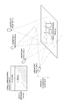
- Fig. 2s are diagrams illustrating the relationship between a projection of a three-dimensional model and a background layer.
- Fig. 2A schematically illustrates the three-dimensional model and the background layer.
- the projection is drawn by perspective projection of the three-dimensional model.
- the drawing range of the projection is called object drawing range. This range is varied by the gaze direction during projection.
- the background layer is provided as a layer showing a background image to be visually recognized as the background in the three-dimensional map. According to the embodiment, the background layer is superimposed not on the rear surface of the projection but on the front surface of the projection as shown in Fig. 2A.
- An upper hatched part of the background layer is an opaque portion in which the image is not transmitted, and a lower non-hatched part of the background layer is a transparent portion in which the image is transmitted.
- a transparent gradation area in which the transmittance of the image is gradually varied may be provided on the boundary between the transparent portion and the opaque section in the background layer.
- Fig. 2B illustrates the state that the background layer is superimposed on the front surface of the projection.
- the projection is visible through the transparent portion of the background layer, the projection is invisible in the opaque portion and the image of the background layer is visible in the opaque portion.
- the transparent gradation area there is an area in which the projection is blurred, on the boundary between the transparent portion and the opaque portion.
- the projection and the background layer are drawn, such that part of the object drawing range is covered and hidden by the opaque portion of the background layer. Covering part of the projection with the background image enables a variety of pseudo-images to be output.
- Fig. 3s are diagrams illustrating the outline of a generation method of a three-dimensional map MAP according to the embodiment.
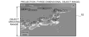
- Fig. 3A illustrates one example of a projection 52.
- the projection 52 is generated by perspective projection using the three-dimensional model 12 read from the map database 10.
- the projection 52 is drawn in a display scale that displays the entire country of Japan.
- Features are drawn in the lower object drawing range of the projection 52, and characters are drawn on the projection 52.
- the horizon should be fundamentally visible as a curved line in this display scale.
- the three-dimensional model is, however, provided in the orthogonal coordinate system, so that the upper edge of the object drawing range is drawn as a straight line in the projection 52.
- Fig. 3B illustrates one example of a background layer 56.
- the background layer 56 is generated by two-dimensionally drawing the background image data 16 read from the map database 10.
- This background layer 56 includes a transparent portion 56a and an opaque portion 56b, and a transparent gradation area 56c in which the transmittance of the image is gradually varied is provided on the boundary.
- An image forming the background of the projection shown in Fig. 3A is drawn in the opaque portion 56b.
- an image representing the stratosphere is drawn in the opaque portion 56b.
- the boundary of the stratosphere is expected to be visible as a curved line following the horizon, so that the boundary of the opaque portion 56b is drawn by a curved line in the background layer 56.
- the background layer 56 is generated by simply drawing the image two-dimensionally, it is easy to drawn the boundary by the curved line.
- the troposphere between the ground surface and the stratosphere is expressed by the transparent gradation area 56c. More specifically, in this transparent gradation area 56c, the transmittance is varied gradually from the transparent state to the opaque state from the transparent portion 56a toward the opaque portion 56b, and the color is changed from white to dark blue expressing the stratosphere.
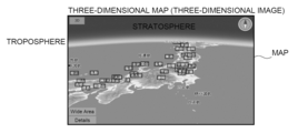
- Fig. 3C illustrates one example of a three-dimensional map (bird's eye view) as a three-dimensional image.
- the background layer 56 is superimposed on the front surface of the projection 52.
- a three-dimensional map MAP on a global scale is output by covering and hiding a straight line section on the upper edge of the projection 52 with the opaque portion 56c of the background layer.
- the boundary of the background layer 56 is drawn by a curved line, so that a pseudo-image in which the horizon is visible as a curved line is generated in Fig. 3C, while the horizon is drawn by a straight line in Fig. 3A.
- this achieves pseudo-expression of the horizon by a pseudo-curved line without describing the three-dimensional model, i.e., the ground surface and the features, by a sphere model or an earth ellipsoid model and without performing any complicated operations.
- the boundary between the opaque portion 56b and the three-dimensional object image 52 transmitted through the transparent portion 56a is blurred to express the troposphere between the ground surface and the stratosphere.
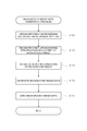
- Background Image Data Generation Process Fig. 4 is a flowchart showing a flow of background image data generation process according to the first embodiment. This process is performed by the CPU of the background image data generation device 200 in response to the operator's instruction to generate the background image data 16 which is stored in the map database 10 of the three-dimensional map display device 100.
- the CPU obtains information regarding specification of the opaque portion 56b of the background layer 56 input by the operator (step S100). For example, the CPU obtains information regarding how many percents of an upper area in the background layer 56 is to be specified as the opaque portion 56b. On the contrary, the CPU may obtain information regarding specification of the transparent portion 56a in the background layer 56. Moreover, the opaque portion is not necessarily a rectangular area. Any of various shapes may be specified as the opaque portion at step S100.
- the CPU subsequently obtains information regarding specification of the content of the background image input by the operator (step S110). For example, in the case of generation of the background image data for the background layer 56 described above with reference to Fig. 3B, the image of the stratosphere of the earth is specified.
- the content of the background image may be specified, for example, by selecting one of image data for backgrounds stored in advance in the background image data generation device 200.
- the CPU subsequently obtains generating conditions of a background image input by the operator (step S120).
- the generating conditions of the background image may be, for example, the curvature of a circular arc or an elliptical arc on the boundary between the opaque portion 56b and the transparent portion 56a in the background layer 56 and the width of the transparent gradation area 56c.
- the CPU generates background image data 16 based on the obtained information and generating conditions of the background image (step S130) and sends the background image data 16 to the three-dimensional map display device 100 (step S140). More specifically, the CPU reads image data of a background corresponding to the content specified at step S110. This image data is data of an entire opaque portion without any transparent portion.
- the CPU specifies part of the image data as the transparent portion, based on the generating conditions of the background image.
- the CPU also provides a transparent gradation area of the specified width.
- One modification may enable the operator to specify part of the image data as the opaque portion. This series of processing completes the background image data generation process of the first embodiment.
- the background image of the embodiment is used to generate a pseudo-image, which is not drawn by simple perspective projection, by covering and hiding part of the projection as described in Figs. 2 and 3.
- the background image representing the stratosphere is used, so that the upper part of the projection is covered and hidden.
- the part of the projection covered and hidden by the background image is, however, not limited to the upper part of the projection.
- Fig. 5 is a diagram illustrating the relationship between the gaze direction and the background image.
- a projection is drawn in a lower part as illustrated in the upper drawing. It is accordingly preferable to specify the upper part of the background image as an opaque portion and the lower part of the background image as a transparent portion and partially hide an upper part of the projection.
- a projection is drawn in an upper part as illustrated in the lower drawing. It is accordingly preferable to specify the upper part of the background image as a transparent portion and the lower part of the background image as an opaque portion and partially hide a lower part of the projection.
- various settings are allowed for the opaque portion and the transparent portion of the background image.
- the opaque portion is not unequivocally determined by the gaze direction.
- an opaque portion may be provided in the lower part with respect to the gaze direction looking down from above in Fig. 5.
- an opaque portion may be provided in the upper part with respect to the gaze direction looking up from below in Fig. 5. This is because the projection may not be necessarily drawn densely, for example, when polygons representing the ground surface are not provided as map data or when the three-dimensional model of buildings is generated more sparsely than the actual state.
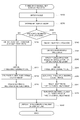
- FIG. 6 is a flowchart showing a flow of three-dimensional map display process according to the first embodiment. This process is performed by the CPU of the three-dimensional map display device 100, in response to input of a display instruction of a three-dimensional map.
- the CPU obtains the scale of a three-dimensional map specified by the user (step S200).
- the CPU subsequently determines the display mode of the three-dimensional map, based on the obtained scale (step S210).
- a background image non-display mode and a background image display mode are provided as the display modes of the three-dimensional map.
- the three-dimensional map MAP is displayed without using the background image data 16 stored in the map database 10.
- the background image non-display mode of the embodiment includes a case of displaying a three-dimensional map MAP, in which the background such as the sea, the mountains, the sky and the clouds is drawn without using the background image data 16.
- the three-dimensional map MAP is displayed using the background image data 16 stored in the map database 10.
- the image of the stratosphere of the earth is used as the background image.
- the background image display mode is applied as the display mode.
- the background image non-display mode is applied as the display mode.
- the CPU subsequently determines whether the display mode determined at step S210 is the background image display mode (step S220).
- the display mode is the background image non-display mode (step S220: NO)
- the CPU obtains the viewpoint position and the gaze direction (step S230) and obtains the three-dimensional model 12 of features as the processing object from the map database 10, based on the scale of the three-dimensional map, the viewpoint position and the gaze direction (step S232).
- the CPU then performs rendering by perspective projection based on the viewpoint position and the gaze direction to generate a three-dimensional object image 52, in which features are drawn three-dimensionally (step S234).
- the background such as the sky and the clouds is drawn appropriately by a prior art technique in the three-dimensional object image 52.
- the CPU obtains the character data 14 from the map database 10 with respect to features displayed in the three-dimensional object image 52, i.e., features visible from the viewpoint position and appropriately draws characters on the three-dimensional object image 52 according to the contents of the character data 14 (step S236).
- the CPU displays a resulting three-dimensional map MAP in the background image non-display mode on the display unit 60 (step S250). After that, the CPU may output the three-dimensional map MAP to the printer 300, in response to the user's output instruction.
- the CPU obtains the viewpoint position (step S240).
- the CPU subsequently obtains the background image data 16 from the map database 10 (step S241) and generates a background layer 56 using the background image data 16.
- the CPU specifies the gaze direction to hide an upper edge of an object drawing range by an opaque portion 56b of the background layer 56 (step S242).
- the background image data 16 is provided in advance, so that the opaque portion 56b of the background layer 56 is specified in advance.
- the size of the object drawing range depends on the gaze direction. The inadequate gaze direction may accordingly result in the case that the stratosphere is invisible or that the object drawing range is not hidden by the opaque portion 56b.
- the CPU sets the gaze direction in this allowable range. According to a modification, when the gaze direction input by the user is out of the allowable range, the CPU may modify the gaze direction to be included in the allowable range.
- the opaque portion 56b of the background layer 56 is specified in advance according to the embodiment but may be specified by analyzing the background image data 16.
- the CPU subsequently obtains the three-dimensional model 12 of features as the processing object from the map database 10, based on the viewpoint position and the gaze direction (step S244).
- the CPU then performs rendering by perspective projection based on the viewpoint position and the gaze direction to generate a three-dimensional object image 52, in which features are drawn three-dimensionally (step S246).
- the CPU subsequently obtains the character data 14 from the map database 10 with respect to features displayed in the three-dimensional object image 52, i.e., features visible from the viewpoint position and appropriately draws characters on the three-dimensional object image 52 according to the contents of the character data 14 (step S247).
- the scale of the three-dimensional map MAP is sufficiently small, so that characters with respect to small features such as buildings and roads are not drawn but only characters representing main geographical names are drawn.
- the CPU then superimposed the background layer 56 on the front surface of the three-dimensional object image 52 with the characters drawn thereon (step S249) and displays a resulting three-dimensional map MAP in the background image display mode on the display unit 60 (step S250). After that, the CPU may output the three-dimensional map MAP to the printer 300, in response to the user's output instruction.
- the three-dimensional map display system of the first embodiment described above superimposes the background layer 56 on the front surface of the three-dimensional object image 52, so as to cause part of the three-dimensional object image 52 to be transmitted through the transparent portion 56a of the background layer 56, to cover and hide part of the three-dimensional object image 52 by the opaque portion 56b of the background layer 56 and to express the boundary between the three-dimensional object image 52 and the stratosphere by a curved line.
- This enables an image that is fundamentally implemented using complicated coordinate conversion or a special three-dimensional model to be expressed by a pseudo-image.
- This enables a variety of backgrounds to be output with the improved reality, while suppressing increases in data volume and processing load in the process of outputting a three-dimensional map MAP, in which features are drawn three-dimensionally, along with a background image.
- the background image data 16 are stored in advance in the map database 10.
- background image data 16 are generated appropriately by a background image data generation device 200A during the three-dimensional map display process.
- Fig. 7 is a diagram schematically illustrating the relationship between the three-dimensional model, the viewpoint position and the object drawing range of a three-dimensional object image.
- the object drawing range of the three-dimensional object image increases with an increase in angle "a" between the gaze direction from the viewpoint position to the three-dimensional model and the ground surface (in the order from the viewpoint position D to the viewpoint position A).
- the boundary between the object drawing range and the background moves upward in the three-dimensional object image.
- the object drawing range of the three-dimensional object image decreases, on the contrary, with a decrease in angle "a" between the gaze direction from the viewpoint position to the three-dimensional model and the ground surface (in the order from the viewpoint position A to the viewpoint position D).
- the boundary between the object drawing range and the background moves downward in the three-dimensional object image.
- the second embodiment accordingly generates background image data 16 according to the change of the object drawing range in the three-dimensional object image.
- Background Image Data Generation Device Fig. 8 is a diagram illustrating the general configuration of the background image data generation device 200A according to the second embodiment.
- the background image data generation device 200A includes a transmitter/ receiver 210, an object drawing range input section 220, a background specifying information input section 230, a background image data generator 240 and a background image storage 250.
- These respective functional blocks are configured as software configuration by installing computer programs for implementing the respective functions in an information processing device including, for example, a CPU, a RAM, a ROM, a hard disk drive and a communication device. At least part of these functional blocks may alternatively be configured as hardware configuration.
- the background image storage 250 stores the materials of a plurality of different background images.
- the materials of the background images include, for example, an image of the stratosphere of the earth and images of the sea, the mountains, the sky and the clouds. Neither transparent portion nor opaque portion is yet formed in these materials.
- the transmitter/ receiver 210 receives various information used for generation of background image data 16 from the three-dimensional map display device 100 and sends the background image data 16 generated by the background image data generation device 200A to the three-dimensional map display device 100.
- the information received from the three-dimensional map display device 100 includes, for example, information specifying an object drawing range in which an object is drawn in a three-dimensional object image 52 and background specifying information specifying the content of a background of the three-dimensional object image 52 in a three-dimensional map MAP.
- the object drawing range input section 220 inputs information specifying an object drawing range in which an object is drawn in a three-dimensional object image 52, from the three-dimensional map display device 100 via the transmitter/ receiver 210.
- the background specifying information input section 230 inputs background specifying information specifying the content of a background of the three-dimensional object image 52 in a three-dimensional map MAP.
- the background image data generator 240 refers to the background image storage 250 based on the information input by the object drawing range input section 220 and the background specifying information input section 230, and generates background image data 16 representing a background image including an opaque portion 56b configured to cover and hide part of the object drawing range in the three-dimensional object image 52 by the specified background and a residual area of the opaque portion 56b specified as a transparent portion 56a.
- FIG. 9 is a flowchart showing a flow of three-dimensional map display process according to the second embodiment. This process is performed by the CPU of the three-dimensional map display device 100 in cooperation with the CPU of the background image data generation device 200A, in response to a display instruction of a three-dimensional map.
- the three-dimensional map display device 100 When a display instruction of a three-dimensional map is input, the three-dimensional map display device 100 obtains the scale of a three-dimensional map specified by the user (step S300). The three-dimensional map display device 100 also obtains the viewpoint position and the gaze direction (step S310). The three-dimensional map display device 100 subsequently determines the display mode of the three-dimensional map, based on the obtained scale, viewpoint position and gaze direction (step S320).
- the three-dimensional map display device 100 then obtains the three-dimensional model 12 of features as the processing object from the map database 10, based on the scale of the three-dimensional map, the viewpoint position and the gaze direction (step S330).
- the three-dimensional map display device 100 then performs rendering by perspective projection based on the viewpoint position and the gaze direction to generate a three-dimensional object image 52, in which features are drawn three-dimensionally (step S340).
- the three-dimensional map display device 100 subsequently obtains the character data 14 from the map database 10 with respect to features displayed in the three-dimensional object image 52, i.e., features visible from the viewpoint position and appropriately draws characters on the three-dimensional object image 52 according to the contents of the character data 14 (step S350).
- the three-dimensional map display device 100 subsequently determines whether the display mode determined at step S320 is the background image display mode (step S360).
- the display mode is the background image non-display mode (step S360: NO)
- the three-dimensional map display device 100 superimposes the three-dimensional object image 52 with the drawn characters on the front surface of a background image provided in advance by a prior art technique and displays a resulting three-dimensional map MAP on the display unit 60 (step S390).
- the three-dimensional map display device 100 may output the three-dimensional map MAP to the printer 300, in response to the user's output instruction.
- the three-dimensional map display device 100 sends various information used for a background image data generation process in the background image data generation device 200A to the background image data generation device 200A (step S362).
- the background image data generation device 200A utilizes the information received from the three-dimensional map display device 100 and performs the background image data generation process described later to generate background image data 16 (step S370).
- the three-dimensional map display device 100 uses the background image data 16 generated by the background image data generation process in the background image data generation device 200A to generate a background layer 56 and superimposes the background layer 56 on the front surface of the three-dimensional object image 52 (step S380) and displays a resulting three-dimensional map MAP on the display unit 60 (step S390). Like the three-dimensional map MAP in the background image display mode of the first embodiment, this three-dimensional map MAP has part of the three-dimensional object image 52 covered and hidden by the opaque portion 56b of the background layer 56. After that, the CPU of the three-dimensional map display device 100 may output the three-dimensional map MAP to the printer 300, in response to the user's output instruction.
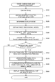
- FIG. 10 is a flowchart showing a flow of background image data generation process according to the second embodiment. This process corresponds to step S370 in the three-dimensional map display process of Fig. 9 and is performed by the CPU of the background image data generation device 200A.
- the background image data generation device 200A receives information specifying an object drawing range in which an object is drawn in a three-dimensional object image 52, from the three-dimensional map display device 100 and inputs the object drawing range (step S400). For example, the input object drawing range shows that lower 80% of the three-dimensional object image 52 is the object drawing range.
- the background image data generation device 200A also receives background specifying information specifying the content of a background of the three-dimensional object image 52 in a three-dimensional map MAP, from the three-dimensional map display device 100 and inputs the background specifying information (step S410).
- the input background specifying information specifies that the background is the stratosphere of the earth or specifies the curvature of a circular arc or an elliptical arc on the boundary between a transparent portion 56a and an opaque portion 56b or the width of a transparent gradation area 56c.
- the background image data generation device 200A then obtains the material of a background image specified by the input background specifying information, from the background image storage 250 (step S420).
- the background image data generation device 200A subsequently determines an opaque portion and a transparent portion of the background image, based on the information (object drawing range and background specifying information) input at steps S400 and S410 (step S430).
- the opaque portion and the transparent portion of the background image are determined, such that part of the object drawing range including the entire uppermost edge is covered and hidden with the opaque portion of the background image.
- the background image data generation device 200A draws the boundary at the specified curvature and adjusts the vertical position of the curved line to locate the apex of the curvature below the uppermost edge of the object drawing range.
- the background image data generation device 200A also adequately determines a transparent gradation area, based on the background specifying information (step S440).
- the background image data generation device 200A generates background image data 16, based on the material of the background image obtained at step S420, the opaque portion and the transparent portion of the background image determined at step S430 and the transparent gradation area determined at step S440 (step S450). More specifically, the background image data generation device 200A reads the image data of the material of the background image, cuts out part of the image data corresponding to the transparent portion and specifies the part as part to be transmitted through.
- the background image data generation device 200A also sets an alpha value to gradually change the transmittance in part of the image data corresponding to the transparent gradation area.
- the CPU of the background image data generation device 200A then sends the generated background image data 16 to the three-dimensional map display device 100 (step S460).
- the three-dimensional map display system of the second embodiment described above superimposes the background layer 56 on the front surface of the three-dimensional object image 52, so as to cause part of the three-dimensional object image 52 to be transmitted through the transparent portion 56a of the background layer 56 and to cover and hide part of the three-dimensional object image 52 by the opaque portion 56b of the background layer 56.
- This enables an image that is fundamentally implemented using complicated coordinate conversion or a special three-dimensional model to be expressed by a pseudo-image.
- This enables a variety of backgrounds to be output with the improved reality, while suppressing increases in data volume and processing load in the process of outputting a three-dimensional map MAP, in which features are drawn three-dimensionally, along with a background image.
- the background image data generation device 200A appropriately and flexibly generates a background image according to the object drawing range and the background specifying information of a three-dimensional object image.
- the image of the stratosphere of the earth is used as the background image (background layer) of the three-dimensional object image 52 in the three-dimensional map MAP.
- the invention is, however, not limited to this embodiment.
- the images of, for example, the sea, the mountains, the sky and the clouds may be used as the background image.
- the boundary between the opaque portion 56b and the transparent portion 56a of the background layer 56 may be expressed by a straight line, instead of the circular arc or the elliptical arc.
- the transparent gradation area 56c may be omitted on the boundary between the opaque portion 56b and the transparent portion 56a.
- Fig. 11 is a diagram illustrating an output example of a three-dimensional map MAP according to a modification.
- this three-dimensional map MAP the mountains, the sky and the clouds are drawn in an opaque portion of a background layer.
- the boundary between the opaque portion and a transparent portion of the background layer is expressed by a straight line.
- a transparent gradation area is provided on the boundary between the opaque portion and the transparent portion of the background layer.
- the prior art method draws a background image behind a projection. This prior art method, however, makes the boundary between the background image and the projection clearly visible and provides a feeling of strangeness.
- the method of the modification places the background layer on the front surface of the projection and provides the transparent gradation area, so as to achieve pseudo-expression of the state that the landscape is gradually blurred at a great distance.
- the modification accordingly employs a flow of three-dimensional map display process, which is partly different from the flow of three-dimensional map display process of the second embodiment shown in Fig. 9. More specifically, the three-dimensional map display process of the modification draws characters on a three-dimensional object image 52 after superimposition of a background layer 56 on the front surface thereof. The following briefly describes the flow of three-dimensional map display process according to the modification.
- Fig. 12 is a flowchart showing the flow of three-dimensional map display process according to the modification.
- the CPU of the three-dimensional map display device 100 obtains the scale of a three-dimensional map specified by the user (step S500), obtains the viewpoint position and the gaze direction (step S510), and determines the display mode of the three-dimensional map, based on the obtained scale, viewpoint position and gaze direction (step S520).
- the CPU of the three-dimensional map display device 100 subsequently obtains the three-dimensional model 12 of features as the processing object from the map database 10, based on the scale of the three-dimensional map, the viewpoint position and the gaze direction (step S530), and performs rendering by perspective projection based on the viewpoint position and the gaze direction to generate a three-dimensional object image 52, in which features are drawn three-dimensionally (step S540).
- This series of processing is identical with the processing of steps S300 to S340 in the three-dimensional map display process of the second embodiment shown in Fig. 9.
- the CPU of the three-dimensional map display device 100 subsequently determines whether the display mode determined at step S520 is the background image display mode (step S550).
- the display mode is the background image non-display mode (step S550: NO)
- the CPU of the three-dimensional map display device 100 superimposes the three-dimensional object image 52 on the front surface of a background image provided in advance by a prior art technique, obtains the character data from the map database 10 with respect to features displayed in the three-dimensional object image 52 and adequately draws characters on the three-dimensional object image 52 according to the contents of the character data 14 (step S580), and displays a resulting three-dimensional map MAP on the display unit 60 (step S590).
- the CPU of the three-dimensional map display device 100 sends various information used for a background image data generation process in the background image data generation device 200A to the background image data generation device 200A (step S552).
- the background image data generation device 200A utilizes the information received from the three-dimensional map display device 100 and performs the background image data generation process to generate background image data 16 (step S560).
- the background image data generation process is identical with that of the second embodiment.
- the CPU of the three-dimensional map display device 100 uses the background image data 16 generated by the background image data generation process in the background image data generation device 200A to generate a background layer 56 and superimposes the background layer 56 on the front surface of the three-dimensional object image 52 (step S570).
- the CPU of the three-dimensional map display device 100 then obtains the character data from the map database 10 with respect to features displayed in the three-dimensional object image 52 and adequately draws characters on the three-dimensional object image 52 after superimposition of the background layer 56 on the front surface thereof, according to the contents of the character data 14 (step S580), and displays a resulting three-dimensional map MAP on the display unit 60 (step S590).
- This series of processing outputs the three-dimensional map MAP according to the modification shown in Fig. 11. Drawing the characters lastly avoids the characters from being hidden by the opaque portion of the background layer.
- the background image data generation device 200A may additionally have a date and time obtaining section that obtains the current date and time.
- the background image data generation device 200A may change the background image according to the current date and time. For example, the color tone of the background may be changed according to the current time, or the color of the mountains may be changed according to the season. This improves the reality of the three-dimensional map MAP.
- Modification 3 The first embodiment described above generates the three-dimensional object image 52, such that part of the three-dimensional object image 52 is covered and hidden by the opaque portion 56b of the background layer 56.
- the second embodiment described above generates the background image data 16, such that part of the three-dimensional object image 52 is covered and hidden by the opaque portion 56b of the background layer 56.
- the invention is, however, not limited to these embodiments.
- a modification may generate both the three-dimensional object image 52 and the background image data 16, while making adjustments, such that part of the three-dimensional object image 52 is covered and hidden by the opaque portion 56b of the background layer 56.
- Modification 5 The above embodiments describe the applications of the three-dimensional image output device and the background image generation device of the invention to the three-dimensional map display system.
- the invention is, however, not limited to these embodiments but may be applied to a navigation system that utilizes a three-dimensional map MAP to guide a route.
- the invention is also applicable to output images other than the map.
- the background of the automobile may be displayed by a background layer to express a pseudo-image showing the running state of the automobile.
- a background layer showing a driver and passengers may be superimposed and drawn on the front surface of the automobile image to express a pseudo-image in the state that people are on the automobile.
- the invention is applicable to technology of outputting a three-dimensional image, in which a background image is superimposed on an image expressing an object three-dimensionally.
- Map database 12 Three-dimensional model 14 Character data 16 Background image data 20 Command input section 30 Transmitter/ receiver 40 Three-dimensional map generator 42 Projecting section 44 Character drawing section 46 Background layer generating section 50 Image output controller 52 Projection (three-dimensional object image) 56 Background layer 56a Transparent portion 56b Opaque portion 56c Transparent gradation area 60 Display unit 100 Three-dimensional map display device 200, 200A Background image data generation device 210 Transmitter/ receiver 220 Object drawing range input section 230 Background specifying information input section 240 Background image data generator 250 Background image storage 300 Printer MAP Three-dimensional map (three-dimensional image) CH1, CH2, CH3, CH4 Character strings
Landscapes
- Engineering & Computer Science (AREA)
- Physics & Mathematics (AREA)
- Remote Sensing (AREA)
- Theoretical Computer Science (AREA)
- General Physics & Mathematics (AREA)
- Radar, Positioning & Navigation (AREA)
- Geometry (AREA)
- Software Systems (AREA)
- Automation & Control Theory (AREA)
- Business, Economics & Management (AREA)
- Educational Administration (AREA)
- Educational Technology (AREA)
- Mathematical Physics (AREA)
- Computer Graphics (AREA)
- Multimedia (AREA)
- Signal Processing (AREA)
- Processing Or Creating Images (AREA)
- Instructional Devices (AREA)
- Image Generation (AREA)
Priority Applications (5)
| Application Number | Priority Date | Filing Date | Title |
|---|---|---|---|
| EP14774190.4A EP2979252A4 (en) | 2013-03-25 | 2014-03-18 | THREE DIMENSIONAL IMAGE OUTPUT DEVICE AND BACKGROUND IMAGE GENERATING DEVICE |
| CN201480018440.8A CN105051791B (zh) | 2013-03-25 | 2014-03-18 | 三维图像输出装置和背景图像生成装置 |
| KR1020157025740A KR20150133201A (ko) | 2013-03-25 | 2014-03-18 | 3차원 이미지 출력 장치 및 배경 이미지 생성 장치 |
| US14/860,572 US9792707B2 (en) | 2013-03-25 | 2015-09-21 | Three-dimensional image output device and background image generation device |
| HK16102820.4A HK1214879A1 (zh) | 2013-03-25 | 2016-03-11 | 三維圖像輸出裝置和背景圖像生成裝置 |
Applications Claiming Priority (2)
| Application Number | Priority Date | Filing Date | Title |
|---|---|---|---|
| JP2013-061214 | 2013-03-25 | ||
| JP2013061214A JP5997640B2 (ja) | 2013-03-25 | 2013-03-25 | 3次元画像出力装置および背景画像生成装置 |
Related Child Applications (1)
| Application Number | Title | Priority Date | Filing Date |
|---|---|---|---|
| US14/860,572 Continuation US9792707B2 (en) | 2013-03-25 | 2015-09-21 | Three-dimensional image output device and background image generation device |
Publications (1)
| Publication Number | Publication Date |
|---|---|
| WO2014156050A1 true WO2014156050A1 (en) | 2014-10-02 |
Family
ID=51623066
Family Applications (1)
| Application Number | Title | Priority Date | Filing Date |
|---|---|---|---|
| PCT/JP2014/001531 WO2014156050A1 (en) | 2013-03-25 | 2014-03-18 | Three-dimensional image output device and background image generation device |
Country Status (7)
| Country | Link |
|---|---|
| US (1) | US9792707B2 (zh) |
| EP (1) | EP2979252A4 (zh) |
| JP (1) | JP5997640B2 (zh) |
| KR (1) | KR20150133201A (zh) |
| CN (1) | CN105051791B (zh) |
| HK (1) | HK1214879A1 (zh) |
| WO (1) | WO2014156050A1 (zh) |
Families Citing this family (12)
| Publication number | Priority date | Publication date | Assignee | Title |
|---|---|---|---|---|
| US10586570B2 (en) | 2014-02-05 | 2020-03-10 | Snap Inc. | Real time video processing for changing proportions of an object in the video |
| US20160042233A1 (en) * | 2014-08-06 | 2016-02-11 | ProSent Mobile Corporation | Method and system for facilitating evaluation of visual appeal of two or more objects |
| US9881399B2 (en) * | 2015-04-15 | 2018-01-30 | Microsoft Technology Licensing, Llc. | Custom map configuration |
| CN105513027A (zh) * | 2016-01-06 | 2016-04-20 | 天脉聚源(北京)科技有限公司 | 一种模糊处理方法及装置 |
| US10181208B2 (en) | 2016-02-10 | 2019-01-15 | Microsoft Technology Licensing, Llc | Custom heatmaps |
| US11579686B2 (en) | 2016-03-07 | 2023-02-14 | Apple Inc. | Method and device for carrying out eye gaze mapping |
| CN106447770A (zh) * | 2016-10-14 | 2017-02-22 | 上海语途信息技术有限公司 | 三维绘图处理方法 |
| US10789723B1 (en) * | 2018-04-18 | 2020-09-29 | Facebook, Inc. | Image object extraction and in-painting hidden surfaces for modified viewpoint rendering |
| CN111415398B (zh) * | 2019-01-08 | 2024-01-05 | 杭州海康威视数字技术股份有限公司 | 一种在显示屏上显示批注的方法及装置 |
| CN111724488B (zh) * | 2019-06-25 | 2022-09-09 | 腾讯科技(深圳)有限公司 | 地图场景绘制方法、装置、可读存储介质和计算机设备 |
| KR102258202B1 (ko) | 2020-02-28 | 2021-05-28 | 서울대학교산학협력단 | 항공기기반 영상복원장치용 가상 해수면모델 생성장치 |
| CN111901581A (zh) * | 2020-08-28 | 2020-11-06 | 南京星邺汇捷网络科技有限公司 | 基于2d视频转3d效果的视频像素处理系统及方法 |
Citations (4)
| Publication number | Priority date | Publication date | Assignee | Title |
|---|---|---|---|---|
| JPH06180742A (ja) * | 1992-10-14 | 1994-06-28 | Hudson Soft Co Ltd | 画像処理方法 |
| JP2002311821A (ja) * | 2001-04-13 | 2002-10-25 | Mitsubishi Electric Corp | ナビゲーションにおける地図表示方法およびナビゲーション装置 |
| JP2007025362A (ja) * | 2005-07-19 | 2007-02-01 | Sega Corp | 画像処理装置、遠景画像表示方法および遠景画像表示プログラム |
| JP2007140842A (ja) * | 2005-11-17 | 2007-06-07 | Namco Bandai Games Inc | プログラム、情報記憶媒体、及び画像生成システム |
Family Cites Families (13)
| Publication number | Priority date | Publication date | Assignee | Title |
|---|---|---|---|---|
| TW371340B (en) | 1992-10-09 | 1999-10-01 | Hudson Soft Co Ltd | Image processing system |
| EP0660290B1 (en) * | 1993-12-27 | 2000-07-12 | Nissan Motor Co., Ltd. | Apparatus and method for navigating vehicle to destination using display unit |
| JP3371605B2 (ja) * | 1995-04-19 | 2003-01-27 | 日産自動車株式会社 | 大気効果表示機能付き鳥瞰図表示ナビゲーションシステム |
| JP3568621B2 (ja) * | 1995-04-20 | 2004-09-22 | 株式会社日立製作所 | 地図表示装置 |
| US7215451B1 (en) * | 1996-04-15 | 2007-05-08 | Dai Nippon Printing Co., Ltd. | Reflection type diffuse hologram, hologram for reflection hologram color filters, etc., and reflection type display device using such holograms |
| JP3695315B2 (ja) * | 2000-11-14 | 2005-09-14 | 日産自動車株式会社 | 車両用表示装置 |
| US8745520B2 (en) * | 2004-05-05 | 2014-06-03 | Adobe Systems Incorporated | User interface including a preview |
| US7369041B2 (en) * | 2004-04-27 | 2008-05-06 | Matsushita Electric Industrial Co., Ltd. | Vehicle surrounding display device |
| US8644644B2 (en) * | 2009-09-14 | 2014-02-04 | Adobe Systems Incorporation | Methods and apparatus for blending images |
| JP5223062B2 (ja) * | 2010-03-11 | 2013-06-26 | 株式会社ジオ技術研究所 | 3次元地図描画システム |
| US8319772B2 (en) * | 2010-07-23 | 2012-11-27 | Microsoft Corporation | 3D layering of map metadata |
| US9135743B2 (en) * | 2012-11-07 | 2015-09-15 | Google Inc. | Visualize the obscure object in 3D space |
| US10181214B2 (en) * | 2013-03-14 | 2019-01-15 | Google Llc | Smooth draping layer for rendering vector data on complex three dimensional objects |
-
2013
- 2013-03-25 JP JP2013061214A patent/JP5997640B2/ja not_active Expired - Fee Related
-
2014
- 2014-03-18 EP EP14774190.4A patent/EP2979252A4/en not_active Withdrawn
- 2014-03-18 CN CN201480018440.8A patent/CN105051791B/zh not_active Expired - Fee Related
- 2014-03-18 WO PCT/JP2014/001531 patent/WO2014156050A1/en active Application Filing
- 2014-03-18 KR KR1020157025740A patent/KR20150133201A/ko active IP Right Grant
-
2015
- 2015-09-21 US US14/860,572 patent/US9792707B2/en active Active
-
2016
- 2016-03-11 HK HK16102820.4A patent/HK1214879A1/zh unknown
Patent Citations (4)
| Publication number | Priority date | Publication date | Assignee | Title |
|---|---|---|---|---|
| JPH06180742A (ja) * | 1992-10-14 | 1994-06-28 | Hudson Soft Co Ltd | 画像処理方法 |
| JP2002311821A (ja) * | 2001-04-13 | 2002-10-25 | Mitsubishi Electric Corp | ナビゲーションにおける地図表示方法およびナビゲーション装置 |
| JP2007025362A (ja) * | 2005-07-19 | 2007-02-01 | Sega Corp | 画像処理装置、遠景画像表示方法および遠景画像表示プログラム |
| JP2007140842A (ja) * | 2005-11-17 | 2007-06-07 | Namco Bandai Games Inc | プログラム、情報記憶媒体、及び画像生成システム |
Non-Patent Citations (1)
| Title |
|---|
| See also references of EP2979252A4 * |
Also Published As
| Publication number | Publication date |
|---|---|
| HK1214879A1 (zh) | 2016-08-05 |
| US9792707B2 (en) | 2017-10-17 |
| EP2979252A1 (en) | 2016-02-03 |
| KR20150133201A (ko) | 2015-11-27 |
| JP5997640B2 (ja) | 2016-09-28 |
| CN105051791B (zh) | 2017-10-03 |
| US20160012627A1 (en) | 2016-01-14 |
| JP2014186568A (ja) | 2014-10-02 |
| EP2979252A4 (en) | 2016-09-07 |
| CN105051791A (zh) | 2015-11-11 |
Similar Documents
| Publication | Publication Date | Title |
|---|---|---|
| WO2014156050A1 (en) | Three-dimensional image output device and background image generation device | |
| US9646416B2 (en) | Three-dimensional map display system | |
| KR101786134B1 (ko) | 비사실적(npr) 3d지도를 사용하는 3d내비게이션 방법 | |
| EP2333488A2 (en) | Personalized and context-sensitive 3d route guidance | |
| JP2009232310A (ja) | 車両用画像処理装置、車両用画像処理方法、車両用画像処理プログラム | |
| US9965894B2 (en) | Three-dimensional map display system | |
| WO2014148040A1 (en) | Three-dimensional map display device | |
| US8531448B2 (en) | Stereoscopic image display apparatus, text data processing apparatus, program, and storing medium | |
| WO2016117267A1 (ja) | 3次元地図表示システム | |
| TW201537533A (zh) | 三次元地圖顯示系統 | |
| US20160012754A1 (en) | Three-dimensional map display device | |
| EP2804149B1 (en) | Water representation by color gradients on a digital map | |
| CN109313824B (zh) | 用于提供交互式地理上下文界面的方法、系统及用户设备 | |
| US20160239996A1 (en) | 3d map display system | |
| US10186073B2 (en) | Image processing device, image processing method, and data structure of image file | |
| KR101873566B1 (ko) | 사용자 스케치기반 지형 저작 시스템 및 방법 | |
| JP4223447B2 (ja) | 映像生成装置 | |
| JP6037985B2 (ja) | 表示画像生成装置、表示画像生成方法 | |
| JP2007108834A (ja) | 広告表示シミュレーション装置、広告表示シミュレーションプログラム、及び広告表示シミュレーション方法 | |
| Domajnko et al. | Designing Photo-Realistic and Abstract Mountain Maps for a 3D Mapping Study |
Legal Events
| Date | Code | Title | Description |
|---|---|---|---|
| WWE | Wipo information: entry into national phase |
Ref document number: 201480018440.8 Country of ref document: CN |
|
| 121 | Ep: the epo has been informed by wipo that ep was designated in this application |
Ref document number: 14774190 Country of ref document: EP Kind code of ref document: A1 |
|
| WWE | Wipo information: entry into national phase |
Ref document number: 2014774190 Country of ref document: EP |
|
| ENP | Entry into the national phase |
Ref document number: 20157025740 Country of ref document: KR Kind code of ref document: A |
|
| NENP | Non-entry into the national phase |
Ref country code: DE |