WO2014155745A1 - 画像処理装置、画像処理方法、情報記憶媒体、及びプログラム - Google Patents
画像処理装置、画像処理方法、情報記憶媒体、及びプログラム Download PDFInfo
- Publication number
- WO2014155745A1 WO2014155745A1 PCT/JP2013/059768 JP2013059768W WO2014155745A1 WO 2014155745 A1 WO2014155745 A1 WO 2014155745A1 JP 2013059768 W JP2013059768 W JP 2013059768W WO 2014155745 A1 WO2014155745 A1 WO 2014155745A1
- Authority
- WO
- WIPO (PCT)
- Prior art keywords
- image
- text
- character
- correction target
- specifying
- Prior art date
- Legal status (The legal status is an assumption and is not a legal conclusion. Google has not performed a legal analysis and makes no representation as to the accuracy of the status listed.)
- Ceased
Links
Images






Classifications
-
- G—PHYSICS
- G06—COMPUTING OR CALCULATING; COUNTING
- G06T—IMAGE DATA PROCESSING OR GENERATION, IN GENERAL
- G06T11/00—Two-dimensional [2D] image generation
- G06T11/60—Creating or editing images; Combining images with text
-
- G—PHYSICS
- G06—COMPUTING OR CALCULATING; COUNTING
- G06F—ELECTRIC DIGITAL DATA PROCESSING
- G06F18/00—Pattern recognition
- G06F18/20—Analysing
- G06F18/22—Matching criteria, e.g. proximity measures
-
- G—PHYSICS
- G06—COMPUTING OR CALCULATING; COUNTING
- G06T—IMAGE DATA PROCESSING OR GENERATION, IN GENERAL
- G06T11/00—Two-dimensional [2D] image generation
- G06T11/10—Texturing; Colouring; Generation of textures or colours
-
- G—PHYSICS
- G06—COMPUTING OR CALCULATING; COUNTING
- G06V—IMAGE OR VIDEO RECOGNITION OR UNDERSTANDING
- G06V10/00—Arrangements for image or video recognition or understanding
- G06V10/70—Arrangements for image or video recognition or understanding using pattern recognition or machine learning
- G06V10/74—Image or video pattern matching; Proximity measures in feature spaces
- G06V10/75—Organisation of the matching processes, e.g. simultaneous or sequential comparisons of image or video features; Coarse-fine approaches, e.g. multi-scale approaches; using context analysis; Selection of dictionaries
- G06V10/751—Comparing pixel values or logical combinations thereof, or feature values having positional relevance, e.g. template matching
- G06V10/7515—Shifting the patterns to accommodate for positional errors
-
- G—PHYSICS
- G06—COMPUTING OR CALCULATING; COUNTING
- G06V—IMAGE OR VIDEO RECOGNITION OR UNDERSTANDING
- G06V20/00—Scenes; Scene-specific elements
- G06V20/60—Type of objects
- G06V20/62—Text, e.g. of license plates, overlay texts or captions on TV images
- G06V20/63—Scene text, e.g. street names
-
- G—PHYSICS
- G06—COMPUTING OR CALCULATING; COUNTING
- G06T—IMAGE DATA PROCESSING OR GENERATION, IN GENERAL
- G06T2207/00—Indexing scheme for image analysis or image enhancement
- G06T2207/20—Special algorithmic details
- G06T2207/20021—Dividing image into blocks, subimages or windows
-
- G—PHYSICS
- G06—COMPUTING OR CALCULATING; COUNTING
- G06V—IMAGE OR VIDEO RECOGNITION OR UNDERSTANDING
- G06V30/00—Character recognition; Recognising digital ink; Document-oriented image-based pattern recognition
- G06V30/10—Character recognition
- G06V30/28—Character recognition specially adapted to the type of the alphabet, e.g. Latin alphabet
- G06V30/287—Character recognition specially adapted to the type of the alphabet, e.g. Latin alphabet of Kanji, Hiragana or Katakana characters
Definitions
- the present invention relates to an image processing apparatus, an image processing method, an information storage medium, and a program, and more particularly to processing of an image integrated with text.
- an image obtained by superimposing a text such as “last day” used in bargains on a background image including elements such as graphics for calling attention may be used.
- text is read from such an image, translated into another language, and a new image is created by superimposing the translated text on the background image, the pre-translation text integrated with the image is removed. It is convenient if you can.
- Patent Document 1 after a character is recognized from a bitmap image obtained by scanning a document in which characters are printed in black on a single color paper, the pixel on which the character is drawn is a pixel having the same attribute as that of the paper. And then re-translate the recognized character to obtain another new character and write it to the back-filled portion of the pixel.
- the problem to be solved by the present invention is to increase the efficiency of the process of removing the text integrated with the image from the image in a series of processes for replacing the text integrated with the image with another text. It is.
- the image processing apparatus is configured so that the first image represented in the original image and the second text represented in the cover image overlap the original image.
- object specifying means for specifying a correction target part that is not covered by the part constituting the second text, and the color of the correction target part in the image
- a correction unit that corrects the attribute
- an output unit that outputs the data specifying the specified correction target portion in association with the composite image.
- the image processing method of the present invention is a composite image in which the covering image is superimposed on the original image so that the first text represented in the original image and the second text represented in the covering image overlap.
- the correction means for specifying the correction target portion that is not covered by the portion forming the second text among the portions forming the first text, and correcting the color attribute of the correction target portion in the image Data specifying the specified correction target portion is output in association with the composite image.
- the program of the present invention is a composite image in which the covering image is superimposed on the original image so that the first text represented in the original image and the second text represented in the covering image overlap.
- Object specifying means for specifying a correction target part that is not covered by the part forming the second text among the parts forming the first text, and correction means for correcting the color attribute of the correction target part in the image
- the information storage medium of the present invention is a composite image in which the covering image is superimposed on the original image so that the first text represented in the original image and the second text represented in the covering image overlap.
- the object specifying means for specifying the correction target part that is not covered by the part forming the second text among the parts forming the first text, and the color attribute of the correction target part in the image are corrected.
- a computer-readable information storage medium storing a program for causing a computer to function as output means for outputting data specifying the specified correction target portion in association with the composite image.
- the color attribute of at least a part of the part constituting the second text is the same as or substantially the same as the color attribute of at least a part of the part constituting the first text.
- the image processing apparatus further includes combining means for generating a composite image by superimposing a cover image on the original image, the target specifying means specifies the correction target portion in the generated composite image, and the correcting means
- the color attribute of the correction target part is determined by using the color attribute of the part corresponding to the correction target part in the approximate area approximated by the color attribute pattern of the target part and the adjacent part including the correction target part and the adjacent part. To do.
- the correction unit specifies the approximate region in the synthesized image or the original image.
- a search range including at least one of a portion constituting the first text and a portion constituting the second text and having a narrower search range than the entire synthesized image is obtained.
- the image processing apparatus further includes range specifying means for specifying in the image, and the correction means specifies the approximate region within the specified search range.
- the range specifying unit specifies the inside of a circumscribed rectangle including a portion constituting the first text and a portion constituting the second text as the search range.
- the correction may further include range specifying means for specifying, in the original image, a search range that includes a portion constituting the first text and is narrower than the entire original image.
- the means specifies the approximate region within the specified search range.
- the synthesizing unit satisfies the predetermined condition relating to the degree to which the portion constituting the first text is covered by the portion constituting the second text. Is to be superimposed on the original image.
- the information processing apparatus further includes a calculation unit that calculates a coverage ratio that represents a ratio of a portion that constitutes the first text covered by a portion that constitutes the second text.
- a calculation unit that calculates a coverage ratio that represents a ratio of a portion that constitutes the first text covered by a portion that constitutes the second text.
- the image processing apparatus further includes an erasing unit that erases the color attribute of the specified correction target portion, and the output unit selects a portion in the correction target image that lacks a color attribute as the correction target portion.
- the composite image from which the color attribute of the correction target portion has been deleted is output to the correction means that recognizes as.
- the correction unit is further provided.
- the present invention since a portion that does not need to be corrected is excluded from the correction target, it is possible to improve the efficiency of the correction processing for removing the text integrated with the image from the image.
- FIG. 1 It is a figure which shows an example of the hardware constitutions of the image processing apparatus which concerns on embodiment of this invention. It is a figure which shows an example of an image. It is a figure which shows an example of the image after an image process. It is a functional block diagram which shows an example of the function implement
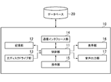
- FIG. 1 is a diagram illustrating an example of a hardware configuration of an image processing apparatus 10 according to an embodiment of the present invention.
- the image processing apparatus 10 is realized by, for example, a server computer, a desktop computer, a laptop computer, or a tablet computer.
- the image processing apparatus 10 includes a control unit 11, a storage unit 12, an optical disc drive unit 13, a communication interface unit 14, an operation unit 15, a display unit 16, and an audio output unit 17.
- the control unit 11 includes, for example, one or a plurality of microprocessors, and executes information processing according to an operating system or a program stored in the storage unit 12.
- the storage unit 12 includes, for example, a RAM, a hard disk, or a solid state drive.
- the optical disk drive unit 13 reads programs and data stored on an optical disk (information storage medium).
- the program and data are supplied to the storage unit 12 via the optical disc. That is, the program and data are read from the optical disk by the optical disk drive unit 13 and stored in the storage unit 12.
- the image processing apparatus 10 may include a component for reading a program or data stored in an information storage medium (for example, a memory card) other than the optical disk. And a program and data may be supplied to the memory
- the communication interface unit 14 is an interface for connecting the image processing apparatus 10 to a communication network.
- the image processing apparatus 10 can exchange data with other apparatuses via a communication network.
- the program and data may be supplied to the storage unit 12 via a communication network.
- the operation unit 15 is for a user to perform an operation.
- a keyboard, a mouse, a touch pad, a touch panel, a stick (lever), or the like corresponds to the operation unit 15.
- the display unit 16 is, for example, a liquid crystal display or an organic EL display.
- the audio output unit 17 is, for example, a speaker or a headphone terminal.
- the image processing apparatus 10 can access the database 20.
- the database 20 may be realized in an apparatus (for example, a server) other than the image processing apparatus 10 or may be realized in the image processing apparatus 10.
- the database 20 stores images. For example, an image used in a virtual shopping mall site provided by a web server (not shown) is stored in the database 20. That is, an image prepared by a person in charge at a store opening a virtual shopping street is stored in the database 20.
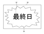
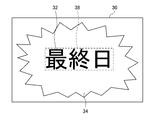
- FIG. 2 is a diagram illustrating an example of the image 30 stored in the database 20.
- An image 30 shown in FIG. 2 is an image in which the character string 32 and the background image 34 are integrated with the character string 32 represented on the background image 34.
- the character string 32 represents a Japanese character string “last day” used in bargains, for example.
- the background image 34 includes, for example, a graphic for calling attention, and includes two or more colors.
- the background image 34 may include more complex elements than geometric figures, such as a photographed image.
- the character string 32 is often written in a conspicuous color different from the background image.
- the character strings 32 are often written in a single color and are often aligned in the horizontal direction, vertical direction, or diagonal direction.
- FIG. 3 is a diagram illustrating an example of the image 39 after the image processing by the image processing apparatus 10.
- the character string 37 obtained by converting the character string 32 of the image 30 is represented on the same background image 34 as the image 30, and the character string 37 and the background image 34 are integrated. It is an image.
- the character string 37 represents, for example, an English character string “FINAL DAY” obtained by translating a Japanese character string “Final Day”.
- the character string 32 before conversion is read from the image 30 as shown in FIG. 2 and converted into another language, and then a new image 39 including the character string 37 after conversion and the background image 34 is generated.
- the technology to do is explained.
- FIG. 4 is a functional block diagram showing functions related to the present invention among the functions realized by the image processing apparatus 10.
- the image processing apparatus 10 includes an original image acquisition unit 41, a character recognition unit 42, a character string conversion unit 43, a character image acquisition unit 44, a synthesis position determination unit 45, an image synthesis unit 46, and a defect A complement 47 is included.
- the character recognition unit 42 includes a constituent pixel specifying unit 42a and a character information acquisition unit 42b.
- the defect complementing unit 47 includes a defective pixel specifying unit 47a, a target patch specifying unit 47b, a similar patch specifying unit 47c, and a pixel value determining unit 47d.
- the functional blocks shown in FIG. 4 are realized by the control unit 11 of the image processing apparatus 10.
- the original image acquisition unit 41 acquires the image 30 from the database 20 and outputs the image 30 to the character recognition unit 42, the image synthesis unit 46, and the loss complementation unit 47.
- the character recognition unit 42 recognizes the character string 32 before conversion included in the image 30.
- the character string 32 before conversion included in the image 30 is an example of the first text.
- a known character recognition process called OCR Optical Character ⁇ Recognition
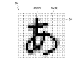
- the character recognizing unit 42 specifies a character area 36 corresponding to each character of the character string 32, and collates the pattern in the character area 36 with a previously registered pattern. Thus, each character of the character string 32 is recognized.
- the constituent pixel specifying unit 42a included in the character recognizing unit 42 specifies constituent pixels constituting the pre-conversion character string 32 included in the image 30, and generates a constituent pixel map representing the position of the constituent pixels as a composite position determining unit 45 and The data is output to the defect complementing unit 47.
- the constituent pixels constituting the character string 32 before conversion are specified by binarizing the character area 36 shown in FIG.
- the pattern of the constituent pixels is used for character recognition processing.
- the character information acquisition unit 42b included in the character recognition unit 42 acquires character information representing the character string 32 before conversion by the character recognition process, and outputs the character information to the character string conversion unit 43.
- the character information includes a character code of each character included in the character string 32, for example.
- the character information representing the character string 32 before conversion is acquired by the character recognition process.
- the present invention is not limited to this mode.
- the character information representing the character string 32 before conversion is included in the image 30. It may be embeddable in a readable manner and obtain it.
- the character string conversion unit 43 converts the character string 32 before conversion and converts the character information representing the character string 37 after conversion into the character image acquisition unit 44. Output to.
- the converted character string 37 converted by the character string conversion unit 43 is an example of a second text.
- the character string 32 is translated into another language. For example, a Japanese character string 32 “final day” is translated into an English character string 37 “FINAL DAY”.
- the character string 32 may be converted into different types of characters in the same language.
- the kanji character string 32 of “last day” may be converted to a hiragana character string “saisuibi” or a katakana character string “saishubi”.
- the number of characters included in the character string is not limited to a plurality, and may be one.
- the character string 32 when the character string 32 represents contents such as date and amount, the character string 32 may be updated to a character string representing new contents corresponding to the contents.
- the control unit 11 acquires information such as the current date or amount and updates the character string 32 to a character string representing the date or amount.
- the character image obtaining unit 44 obtains a character image representing the converted character string 37 from a font database (not shown), and combines the composition position determining unit 45 and the image.
- the data is output to the combining unit 46.
- the character image representing the converted character string 37 is rasterized and output.
- the character image representing the converted character string 37 is output as it is.
- the composite position determination unit 45 is an example of a calculation unit, and a portion in which non-transparent pixels of a character image constitute a character string 32 before conversion included in the image 30 as a portion constituting the character string 37 after conversion.
- the composition position of the character image representing the character string 37 after the conversion is determined so that the degree of covering the constituent pixels as follows satisfies a predetermined condition.
- the image composition unit 46 is an example of composition means, and composes a character image representing the character string 37 after conversion on the character string 32 before conversion of the image 30. Specifically, the character image representing the converted character string 37 is combined at the position determined by the combining position determination unit 45 on the image 30.
- the defect complementing unit 47 regards a part that is not covered by the part that constitutes the converted character string 37 among the parts that constitute the character string 32 before the conversion of the image 30 as the correction target part, and the color attribute of the correction target part Correct. Specifically, the defect complementation unit 47 regards pixels that are not covered by the character image representing the character string 37 after conversion among the constituent pixels that constitute the character string 32 before conversion of the image 30 as defective pixels.
- the pixel value of a pixel is complemented based on the pixel value of another pixel.
- the missing pixel is an example of a correction target portion, and the pixel value is an example of a color attribute. A method for complementing the defective pixel will be described in detail later.
- the missing pixel specifying unit 47a included in the missing complementing unit 47 is an example of a target specifying unit, an output unit, and an erasing unit, and the missing in the image 30 after the character image representing the converted character string 37 is synthesized. Specify the pixel.
- the missing pixel specifying unit 47a associates the data specifying the missing pixel with the combined image 30 and outputs the data to the target patch specifying unit 47b and the pixel value determining unit 47d.
- the data specifying the defective pixel includes, for example, coordinate data representing the position of the defective pixel in the combined image 30.
- the target patch specifying unit 47b included in the defect complementing unit 47 specifies the target patch in the image 30 after the character image representing the converted character string 37 is synthesized.
- the target patch is an example of a target region, and includes a defective pixel as a correction target portion and an adjacent pixel as an adjacent portion thereof.
- the similar patch specifying unit 47c included in the defect complementing unit 47 is an example of a range specifying unit, and the character string 37 in the image 30 after the character image representing the character string 37 after conversion is synthesized or the character string 37 after conversion is displayed.
- a similar patch corresponding to the target patch is specified in the image 30 before the character image to be represented is synthesized.
- a similar patch is an example of an approximate region. Note that the similar patch specifying unit 47c may narrow down a search range for searching for a similar patch in the image 30 after combining or before.
- the similar patch refers to a plurality of candidate patches identified in the image 30 that are similar to the target patch. Similarity means that the pixel values of adjacent pixels included in the target patch are close to the pixel values of the pixels in the candidate patch corresponding to the adjacent pixels.
- the pixel value determining unit 47d included in the defect complementing unit 47 is an example of a correction unit, and determines the pixel value of the defective pixel based on the pixel value of the pixel included in the similar patch. Specifically, the pixel value of the missing pixel included in the target patch is determined based on the pixel value of the pixel in the similar patch corresponding to the missing pixel.
- the functional blocks shown in FIG. 4 may be distributed to a plurality of devices.
- character recognition processing by the character recognition unit 42, image synthesis processing by the image synthesis unit 46, and defect processing by the defect complementation unit 47 may be executed by different devices. Further, these processes may be separated in time, and in this case, data generated by the character recognition process or the image composition process may be temporarily stored in the database.
- the client may execute a part of the processing in accordance with a command from the server.
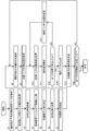
- the defect complementation unit 47 is a process executed by the image processing apparatus 10 in order to realize the missing pixel designation unit 47 a, the target patch identification unit 47 b, the similar patch identification unit 47 c, and the pixel value determination unit 47 d. It is a flowchart which shows an example.
- the control unit 11 executes the processing shown in FIG. 5 according to the program, the control unit 11 causes the defect complementing unit 47, the defective pixel specifying unit 47a, the target patch specifying unit 47b, the similar patch specifying unit 47c, and the pixel value determining unit 47d. Will function as.
- the details of the defect complementing unit 47, the defective pixel specifying unit 47a, the target patch specifying unit 47b, the similar patch specifying unit 47c, and the pixel value determining unit 47d will be described with reference to FIG.
- control unit 11 acquires the constituent pixel map 50 of the pre-translation character string 32.
- FIG. 7 is a diagram illustrating an example of the pre-translation character string 32 included in the image 30.
- the character “A” is represented as a character included in the pre-translation character string 32.
- the background of the character “A” is made colorless for easy understanding, but the background image 34 actually has one or more kinds of colors.
- the image 30 has a character portion 33 related to the pre-translation character string 32 and a background portion 35 related to the background image 34.
- each character of the pre-translation character string 32 when anti-aliasing is applied to each character of the pre-translation character string 32, a plurality of types of pixels having different brightness values exist in the vicinity of the boundary with the background portion 35 in the character portion 33.
- the pixels of the character portion 33 included in the image 30 are specified as the constituent pixels constituting the pre-translation character string 32.
- the character portion 33 is a pixel set including one or a plurality of constituent pixels constituting the pre-translation character string 32.
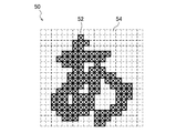
- FIG. 8 is a diagram showing an example of the constituent pixel map 50 of the character string 32 before translation.
- the constituent pixel map 50 includes constituent pixels 52 that constitute each character of the pre-translation character string 32 and non-constituent pixels 54 that are background pixels that do not constitute a character.
- the pixels marked with “x” represent the constituent pixels 52
- the pixels not marked with the “x” represent non-configured pixels 54.
- the constituent pixel 52 of the constituent pixel map 50 shown in the figure corresponds to the pixel of the character portion 33 representing the character “A” in the image 30 shown in FIG.
- control unit 11 acquires the character image 60 of the post-translation character string 37.
- FIG. 9 is a diagram illustrating an example of the character image 60 of the translated character string 37.
- the character “A” is represented as the character included in the translated character string 37.
- the character image 60 includes non-transparent pixels 61 that constitute each character of the translated character string 37 and transparent pixels 63 that do not constitute a character.
- the non-transparent pixel 61 includes a plurality of types of pixels having different brightness.
- each part of the part (set of non-transparent pixels 61) constituting the post-translation character string 37 of the character image 60 corresponds to the character part 33 related to the pre-translation character string 32 of the image 30.
- Each part has the same or substantially the same color attribute.
- the size of the character image 60 of the translated character string 37 is the size of the character region 36 (see FIGS. 6 and 7) specified in the image 30 or a region in which a plurality of character regions 36 are connected. It is determined according to the size of.
- the character image 60 of the translated character string is an example of a cover image.
- the cover image may be, for example, an image obtained by combining the character image 60 with a transparent image having the same size as the original image 30.
- control unit 11 acquires a synthesis position where the character image 60 representing the post-conversion character string 37 is synthesized on the image 30.
- the composite position is determined by the composite position determination unit 45 shown in FIG. 4 based on the constituent pixel map 50 of the pre-translation character string 32 and the character image 60 of the post-translation character string 37. Specifically, the composition position determination unit 45 determines the composition position so that the coverage of the non-transparent pixels 61 of the character image 60 covering the constituent pixels 52 of the constituent pixel map 50 is greater than or equal to a predetermined threshold. . The coverage is expressed as a ratio of the number of constituent pixels 52 covered by the non-transparent pixels 61 of the character image 60 to the total number of constituent pixels 52 of the constituent pixel map 50. For example, the composition position determination unit 45 calculates the coverage ratio each time the character image 60 is moved one or more pixels on the constituent pixel map 50, and determines the position with the highest coverage ratio as the composition position. .
- control unit 11 compares the constituent pixel map 50 of the pre-translation character string 32 with the character image 60 of the post-translation character string 37. As the position of the character image 60 when compared with the component pixel map 50, the composite position acquired in S3 is used.
- FIG. 10 is a diagram showing an example of comparison between the constituent pixel map 50 and the character image 60 (note that FIG. 10 is also a diagram showing an example of synthesis of an image 30 and a character image 60 described later).
- FIG. 10 is also a diagram showing an example of synthesis of an image 30 and a character image 60 described later.
- the position of the constituent pixel 52 that is not covered by the non-transparent pixel 61 of the character image 60 that is, when the character image 60 is synthesized on the image 30,
- the position of the character portion 33 that is not covered by the non-transparent pixel 61 of the character image 60 is specified.
- control unit 11 determines the position of the constituent pixel 52 that is not covered by the non-transparent pixel 61 of the character image 60, which is specified by the comparison of S4, as the position of the defective pixel D.
- the control unit 11 acquires the image 30 in which the character image 60 is synthesized.
- the characters of the image 30 that are not covered with the non-transparent pixels 61 in the vicinity of the outer edge of the character represented by the non-transparent pixels 61 of the character image 60. A portion 33 is left.
- the control unit 11 designates the pixel of the character portion 33 of the image 30 that is not covered by the non-transparent pixel 61 as the missing pixel D in the image 30 in which the character image 60 is synthesized. For example, at this time, the pixel value of the pixel designated as the defective pixel D is erased (that is, 0). Thus, when the pixel value of the pixel designated as the defective pixel D is erased, it is possible to simplify the complementing process described below.
- the designation of the defective pixel D is not limited to the erasure of the pixel value. For example, coordinate data representing the position of the missing pixel D in the combined image 30 may be generated.
- a complementing process for complementing the pixel value of the defective pixel D in the image 30 with the synthesized character image 60 based on the pixel values of other pixels is executed.
- a known complementing method such as inpainting is applied.
- the present invention is not limited to this, and other complementary methods such as linear interpolation may be used.
- the control unit 11 selects one defective pixel D to be complemented from the plurality of defective pixels D.
- the defective pixel D to be complemented is selected, the defective pixel D having a large number of adjacent pixels having pixel values is preferentially selected as the complement target. For example, when a plurality of missing pixels D are gathered, the missing pixels D close to the periphery are preferentially selected as complementing targets.
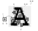
- FIG. 11 is a diagram illustrating an example of specifying the target patch 7.
- the target patch 7 has a defective pixel region 72 formed at the center and an adjacent pixel region 74 formed around the defective pixel region 72.
- the defective pixel area 72 is an area for the defective pixel D selected as the complement target.
- the adjacent pixel area 74 is an area for an adjacent pixel adjacent to the defective pixel D.
- the adjacent pixels include four non-transparent pixels 61, three background portion 35 pixels, and one missing pixel D.
- the non-transparent pixels 61 are concentrated on the right half of the target patch 7, and the pixels of the background portion 35 are concentrated on the left half of the target patch 7.
- the size of the target patch 7 is 3 ⁇ 3 pixels, but may be larger than this.
- the control unit 11 acquires the pixel value of the pixel of the target patch 7 specified in the image 30 in which the character image 60 is synthesized. Specifically, the control unit 11 acquires the pixel value of each pixel included in the adjacent pixel region 74 of the target patch 7.
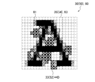
- the control unit 11 specifies the candidate patch 8 in the image 30 in which the character image 60 is synthesized, and acquires the pixel value of the pixel of the candidate patch 8 as shown in FIG. Specifically, the control unit 11 acquires the pixel value of each pixel included in the adjacent corresponding region 83 of the candidate patch 8.
- the candidate patch 8 is a patch corresponding to the target patch 7 for determining a similar patch 9 similar to the target patch 7.
- FIG. 12 is a diagram illustrating an example of specifying the similar patch 9.
- the candidate patch 8 has a defect corresponding region 81 formed at the center and an adjacent corresponding region 83 formed around the candidate corresponding region 81.
- the defect correspondence area 81 is an area corresponding to the defect pixel area 72 of the target patch 7.
- the adjacent corresponding area 83 is an area corresponding to the adjacent pixel area 74 of the target patch 7.
- the control unit 11 calculates the similarity between the pixel value of the pixel of the target patch 7 and the pixel value of the pixel of the candidate patch 8.
- the similarity is, for example, the sum of squares of the difference between the pixel value of each pixel included in the adjacent pixel area 74 of the target patch 7 and the pixel value of each pixel included in the adjacent corresponding area 83 of the candidate patch 8.
- S10 and S11 are repeated each time while shifting the candidate patch 8 by one or more pixels in the image 30 in which the character image 60 is synthesized (S12 and S13). Thereby, the similarity at each position of the candidate patch 8 is calculated.
- the control unit 11 determines the similar patch 9 based on the similarity at each position of the candidate patch 8. Specifically, the candidate patch 8 having the highest similarity is determined as the similar patch 9.
- the non-transparent pixels 61 are concentrated on the right half of the similar patch 9, and the pixels of the background portion 35 are concentrated on the left half of the similar patch 9. Yes.
- the control unit 11 determines the pixel value of the defective pixel D based on the pixel value of the pixel of the similar patch 9. Specifically, the pixel value of the missing pixel D in the missing pixel region 72 of the target patch 7 is determined based on the pixel value of the pixel in the missing corresponding region 92 of the similar patch 9. For example, the same value as the pixel value of the pixel in the defect corresponding area 92 is applied as the pixel value of the defective pixel D in the defect pixel area 72. In this way, the pixel value of the defective pixel D to be complemented is complemented.
- the pixel of the character portion 33 of the image 30 that is not covered with the non-transparent pixel 61 is regarded as the defective pixel D, and the defective pixel D Since the number of missing pixels D can be reduced as compared with the case where the pixel values of all the pixels of the character portion 33 of the image 30 are complemented, the processing load of the complement processing is reduced. Thus, efficiency can be improved.
- the set of missing pixels D can be dispersed or reduced in size, so that it is possible to improve complementation accuracy.
- the defective pixel D is likely to be generated near the outer edge of the character represented by the non-transparent pixel 61 of the character image 60
- the character represented by the non-transparent pixel 61 in the target patch 7 is determined.
- the outer edge is likely to be included (that is, the non-transparent pixel 61 and the background portion 35 are likely to be mixed in the target patch 7).
- the similar patch 9 is also determined in the vicinity of the outer edge of the character represented by the non-transparent pixel 61, so that it is possible to improve the complementary accuracy in the vicinity of the outer edge of the character.
- the character represented by the non-transparent pixel 61 of the character image 60 is anti-aliased, or when the background portion 35 of the image 30 is a fine pattern of two or more colors. Is particularly effective.
- the identification of the similar patch 9 in S10 to S14 may be performed in the image 30 in which the character image 60 is not synthesized. That is, as illustrated in FIG. 13, the control unit 11 specifies each candidate patch 8 in the image 30 including the pre-translation character string 32, calculates the similarity, and includes the pre-translation character string 32 in the image 30.
- the similar patch 9 may be determined by the above. According to this, based on the pixel value of the pixel of the similar patch 9 determined in the image 30 including the pre-translation character string 32, the target patch 7 identified in the image 30 synthesized with the character image 60 (FIG. 11). The pixel value of the defective pixel D is determined.
- the character image 60 before the character image 60 is synthesized. It can be expected that the state of the pixels in the original image 30, particularly the state of the pixels near the outer edge of the character portion 33, can be reproduced more easily.
- the identification of the similar patch 9 in S10 to S13 may be performed in a partial area (search area 38) corresponding to the pre-translation character string 32 in the image 30.
- search area 38 is set so that the pre-translation character string 32 is included in the pre-combination image 30.
- the search area 38 is set so that at least one of the pre-translation character string 32 and the post-translation character string 37 is included in the combined image 30.
- the inside of the circumscribed rectangle including both the pre-translation character string 32 and the post-translation character string 37 is preferably set as the search area 38.
- the similar patch 9 is easily determined in the vicinity of the outer edge of the character represented by the non-transparent pixel 61 (in the case of the image 30, in the vicinity of the outer edge of the character portion 33).
- it has little effect on complementation accuracy. That is, by setting the search area 38 as described above, the search area 38 is narrowed down to an area where the similar patch 9 is likely to appear, so that the processing load of the complementary processing is further reduced and the efficiency is further improved. It is possible to make it.
- the pixel value of the pixel designated as the defective pixel D is erased and the pixel value of the defective pixel D is complemented from 0 to a new value.
- the present invention is not limited to this mode. Correction of increasing or decreasing the pixel value may be performed without deleting the pixel value of the pixel designated as the pixel D.
Landscapes
- Engineering & Computer Science (AREA)
- Theoretical Computer Science (AREA)
- General Physics & Mathematics (AREA)
- Physics & Mathematics (AREA)
- Computer Vision & Pattern Recognition (AREA)
- Multimedia (AREA)
- Evolutionary Computation (AREA)
- Artificial Intelligence (AREA)
- Software Systems (AREA)
- Databases & Information Systems (AREA)
- Medical Informatics (AREA)
- General Health & Medical Sciences (AREA)
- Data Mining & Analysis (AREA)
- Health & Medical Sciences (AREA)
- Computing Systems (AREA)
- Bioinformatics & Computational Biology (AREA)
- General Engineering & Computer Science (AREA)
- Evolutionary Biology (AREA)
- Bioinformatics & Cheminformatics (AREA)
- Life Sciences & Earth Sciences (AREA)
- Processing Or Creating Images (AREA)
- Image Processing (AREA)
Abstract
Description
Claims (13)
- 原画像に表される第1のテキストと被覆画像に表される第2のテキストとが重なるように前記原画像上に前記被覆画像が重畳された合成画像において、前記第1のテキストを構成する部分のうち、前記第2のテキストを構成する部分により被覆されない補正対象部分を特定する対象特定手段と、
画像内の補正対象部分の色属性を補正する補正手段に、前記特定された補正対象部分を指定するデータを前記合成画像に関連付けて出力する出力手段と、
を備える画像処理装置。 - 前記第2のテキストを構成する部分の少なくとも一部の色属性が前記第1のテキストを構成する部分の少なくとも一部の色属性と同一又は略同一である前記被覆画像を前記原画像上に重畳して前記合成画像を生成する合成手段をさらに備え、
前記対象特定手段は、前記生成された合成画像において前記補正対象部分を特定し、
前記補正手段は、前記補正対象部分とその隣接部分とを含む対象領域と隣接部分の色属性パターンが近似する近似領域における該補正対象部分に対応する部分の色属性を利用して、該補正対象部分の色属性を決定する、
請求項1に記載の画像処理装置。 - 前記補正手段は、前記近似領域を前記合成画像内又は前記原画像内で特定する、
請求項2に記載の画像処理装置。 - 前記第1のテキストを構成する部分と前記第2のテキストを構成する部分との少なくとも一方を含み、かつ前記合成画像の全体よりも狭い探索範囲を、該合成画像内において特定する範囲特定手段をさらに備え、
前記補正手段は、前記特定された探索範囲内において前記近似領域を特定する、
請求項2または3に記載の画像処理装置。 - 前記範囲特定手段は、前記第1のテキストを構成する部分と前記第2のテキストを構成する部分とを含む外接矩形の内部を前記探索範囲として特定する、
請求項4に記載の画像処理装置。 - 前記第1のテキストを構成する部分を含み、かつ前記原画像の全体よりも狭い探索範囲を、該原画像内において特定する範囲特定手段をさらに備え、
前記補正手段は、前記特定された探索範囲内において前記近似領域を特定する、
請求項2または3に記載の画像処理装置。 - 前記合成手段は、前記第2のテキストを構成する部分により前記第1のテキストを構成する部分が被覆される度合いに関する所定の条件を満たすように、前記被覆画像を前記原画像上に重畳させる位置を決定する、
請求項2ないし6の何れかに記載の画像処理装置。 - 前記第2のテキストを構成する部分により前記第1のテキストを構成する部分が被覆される割合を表す被覆率を算出する算出手段をさらに備え、
前記合成手段は、前記算出された被覆率が所定の閾値以上又は超過の場合に、前記所定の条件を満たすと判定する、
請求項7に記載の画像処理装置。 - 前記特定された補正対象部分の色属性を消去する消去手段をさらに備え、
前記出力手段は、補正対象の画像内における色属性が欠落した部分を前記補正対象部分として認識する前記補正手段に、前記補正対象部分の色属性が消去された前記合成画像を出力する、
請求項1ないし8の何れかに記載の画像処理装置。 - 前記補正手段をさらに備える、
請求項1ないし9の何れかに記載の画像処理装置。 - 原画像に表される第1のテキストと被覆画像に表される第2のテキストとが重なるように前記原画像上に前記被覆画像が重畳された合成画像において、前記第1のテキストを構成する部分のうち、前記第2のテキストを構成する部分により被覆されない補正対象部分を特定し、
画像内の補正対象部分の色属性を補正する補正手段に、前記特定された補正対象部分を指定するデータを前記合成画像に関連付けて出力する、
画像処理方法。 - 原画像に表される第1のテキストと被覆画像に表される第2のテキストとが重なるように前記原画像上に前記被覆画像が重畳された合成画像において、前記第1のテキストを構成する部分のうち、前記第2のテキストを構成する部分により被覆されない補正対象部分を特定する対象特定手段、及び、
画像内の補正対象部分の色属性を補正する補正手段に、前記特定された補正対象部分を指定するデータを前記合成画像に関連付けて出力する出力手段、
としてコンピュータを機能させるプログラム。 - 原画像に表される第1のテキストと被覆画像に表される第2のテキストとが重なるように前記原画像上に前記被覆画像が重畳された合成画像において、前記第1のテキストを構成する部分のうち、前記第2のテキストを構成する部分により被覆されない補正対象部分を特定する対象特定手段、及び、
画像内の補正対象部分の色属性を補正する補正手段に、前記特定された補正対象部分を指定するデータを前記合成画像に関連付けて出力する出力手段、
としてコンピュータを機能させるプログラムを記録したコンピュータ読み取り可能な情報記憶媒体。
Priority Applications (3)
| Application Number | Priority Date | Filing Date | Title |
|---|---|---|---|
| JP2013550700A JP5512903B1 (ja) | 2013-03-29 | 2013-03-29 | 画像処理装置、画像処理方法、情報記憶媒体、及びプログラム |
| PCT/JP2013/059768 WO2014155745A1 (ja) | 2013-03-29 | 2013-03-29 | 画像処理装置、画像処理方法、情報記憶媒体、及びプログラム |
| US14/439,662 US9519984B2 (en) | 2013-03-29 | 2013-03-29 | Image processing device, image processing method, information storage medium, and program |
Applications Claiming Priority (1)
| Application Number | Priority Date | Filing Date | Title |
|---|---|---|---|
| PCT/JP2013/059768 WO2014155745A1 (ja) | 2013-03-29 | 2013-03-29 | 画像処理装置、画像処理方法、情報記憶媒体、及びプログラム |
Publications (1)
| Publication Number | Publication Date |
|---|---|
| WO2014155745A1 true WO2014155745A1 (ja) | 2014-10-02 |
Family
ID=51031164
Family Applications (1)
| Application Number | Title | Priority Date | Filing Date |
|---|---|---|---|
| PCT/JP2013/059768 Ceased WO2014155745A1 (ja) | 2013-03-29 | 2013-03-29 | 画像処理装置、画像処理方法、情報記憶媒体、及びプログラム |
Country Status (3)
| Country | Link |
|---|---|
| US (1) | US9519984B2 (ja) |
| JP (1) | JP5512903B1 (ja) |
| WO (1) | WO2014155745A1 (ja) |
Families Citing this family (6)
| Publication number | Priority date | Publication date | Assignee | Title |
|---|---|---|---|---|
| CN110032997B (zh) * | 2019-01-07 | 2021-02-19 | 武汉大学 | 一种基于图像分割的自然场景文本定位方法 |
| US11347381B2 (en) * | 2019-06-13 | 2022-05-31 | International Business Machines Corporation | Dynamic synchronized image text localization |
| US11145119B2 (en) | 2019-10-18 | 2021-10-12 | Omniscient Neurotechnology Pty Limited | Differential brain network analysis |
| CN111160265B (zh) * | 2019-12-30 | 2023-01-10 | Oppo(重庆)智能科技有限公司 | 文件转换方法、装置、存储介质及电子设备 |
| WO2021230863A1 (en) | 2020-05-13 | 2021-11-18 | Google Llc | Image replacement inpainting |
| CN114520875B (zh) * | 2022-01-28 | 2024-04-02 | 西安维沃软件技术有限公司 | 视频处理方法、装置及电子设备 |
Citations (2)
| Publication number | Priority date | Publication date | Assignee | Title |
|---|---|---|---|---|
| JP2006251902A (ja) * | 2005-03-08 | 2006-09-21 | Fuji Xerox Co Ltd | 翻訳文書画像生成装置、翻訳文書画像生成プログラム及び翻訳文書画像生成方法 |
| JP2009053838A (ja) * | 2007-08-24 | 2009-03-12 | Fuji Xerox Co Ltd | 翻訳装置及びプログラム |
Family Cites Families (4)
| Publication number | Priority date | Publication date | Assignee | Title |
|---|---|---|---|---|
| US20030200078A1 (en) * | 2002-04-19 | 2003-10-23 | Huitao Luo | System and method for language translation of character strings occurring in captured image data |
| JP2008084286A (ja) * | 2006-09-01 | 2008-04-10 | Toshiba Corp | 電子漫画配信サーバ、および翻訳電子漫画作成装置 |
| US8144990B2 (en) * | 2007-03-22 | 2012-03-27 | Sony Ericsson Mobile Communications Ab | Translation and display of text in picture |
| US9104661B1 (en) * | 2011-06-29 | 2015-08-11 | Amazon Technologies, Inc. | Translation of applications |
-
2013
- 2013-03-29 JP JP2013550700A patent/JP5512903B1/ja active Active
- 2013-03-29 WO PCT/JP2013/059768 patent/WO2014155745A1/ja not_active Ceased
- 2013-03-29 US US14/439,662 patent/US9519984B2/en active Active
Patent Citations (2)
| Publication number | Priority date | Publication date | Assignee | Title |
|---|---|---|---|---|
| JP2006251902A (ja) * | 2005-03-08 | 2006-09-21 | Fuji Xerox Co Ltd | 翻訳文書画像生成装置、翻訳文書画像生成プログラム及び翻訳文書画像生成方法 |
| JP2009053838A (ja) * | 2007-08-24 | 2009-03-12 | Fuji Xerox Co Ltd | 翻訳装置及びプログラム |
Also Published As
| Publication number | Publication date |
|---|---|
| JP5512903B1 (ja) | 2014-06-04 |
| US9519984B2 (en) | 2016-12-13 |
| US20160035116A1 (en) | 2016-02-04 |
| JPWO2014155745A1 (ja) | 2017-02-16 |
Similar Documents
| Publication | Publication Date | Title |
|---|---|---|
| JP5512903B1 (ja) | 画像処理装置、画像処理方法、情報記憶媒体、及びプログラム | |
| JP2012203458A (ja) | 画像処理装置及びプログラム | |
| US7729013B2 (en) | Image processing apparatus, image processing method, and computer program product | |
| JP4142614B2 (ja) | トラッピング方法、トラッピングプログラム、トラッピング装置および印刷システム | |
| JP4125273B2 (ja) | 画像処理装置及びその方法、プログラム | |
| US20190361907A1 (en) | Method for providing e-book service and computer program therefor | |
| JP5858188B1 (ja) | 画像処理装置、画像処理方法、画像処理システムおよびプログラム | |
| CN112927314A (zh) | 一种图像数据处理方法、装置以及计算机设备 | |
| US9905030B2 (en) | Image processing device, image processing method, information storage medium, and program | |
| JP6337680B2 (ja) | 画像処理システム、画像処理装置、プログラム及び画像処理方法 | |
| US9558574B2 (en) | Method and system for conflating raster and vector data | |
| JP5080297B2 (ja) | 画像表示装置 | |
| US20120159292A1 (en) | Method of processing an object-based image file with content type dependent image processing algorithms | |
| JP5672168B2 (ja) | 画像処理装置、画像処理方法及びプログラム | |
| JP6194781B2 (ja) | 画像処理装置及びプログラム | |
| JP2006254342A (ja) | 画像処理装置 | |
| JP2016139360A (ja) | コンピュータプログラム及び制御装置 | |
| KR102853798B1 (ko) | 디지털 문서에서의 컴포넌트 자동 조정 및 정렬 시스템 및 방법과 이를 수행하는 프로그램 | |
| JP4551906B2 (ja) | 画像処理装置 | |
| CN111091606A (zh) | 基于地图覆盖物渐变的解决方法 | |
| JP2010165070A (ja) | 描画編集方法及び描画編集装置 | |
| JP4736489B2 (ja) | 画像処理装置 | |
| JP2005142791A (ja) | トラッピング方法、トラッピング装置、トラッピングプログラム、および印刷システム | |
| KR100586602B1 (ko) | 라스터 맵 오버레이 방법 | |
| JP2004126971A (ja) | グラフィカルユーザインターフェース用部品生成装置、生成方法、生成プログラム、及び該プログラムを記録したコンピュータ読み取り可能な記録媒体 |
Legal Events
| Date | Code | Title | Description |
|---|---|---|---|
| ENP | Entry into the national phase |
Ref document number: 2013550700 Country of ref document: JP Kind code of ref document: A |
|
| 121 | Ep: the epo has been informed by wipo that ep was designated in this application |
Ref document number: 13880330 Country of ref document: EP Kind code of ref document: A1 |
|
| WWE | Wipo information: entry into national phase |
Ref document number: 14439662 Country of ref document: US |
|
| NENP | Non-entry into the national phase |
Ref country code: DE |
|
| 122 | Ep: pct application non-entry in european phase |
Ref document number: 13880330 Country of ref document: EP Kind code of ref document: A1 |