WO2014155598A1 - 港湾荷役機器の制御方法と港湾荷役機器 - Google Patents
港湾荷役機器の制御方法と港湾荷役機器 Download PDFInfo
- Publication number
- WO2014155598A1 WO2014155598A1 PCT/JP2013/059225 JP2013059225W WO2014155598A1 WO 2014155598 A1 WO2014155598 A1 WO 2014155598A1 JP 2013059225 W JP2013059225 W JP 2013059225W WO 2014155598 A1 WO2014155598 A1 WO 2014155598A1
- Authority
- WO
- WIPO (PCT)
- Prior art keywords
- main
- cargo handling
- main machine
- indoor
- machine
- Prior art date
- Legal status (The legal status is an assumption and is not a legal conclusion. Google has not performed a legal analysis and makes no representation as to the accuracy of the status listed.)
- Ceased
Links
Images



Classifications
-
- B—PERFORMING OPERATIONS; TRANSPORTING
- B66—HOISTING; LIFTING; HAULING
- B66C—CRANES; LOAD-ENGAGING ELEMENTS OR DEVICES FOR CRANES, CAPSTANS, WINCHES, OR TACKLES
- B66C13/00—Other constructional features or details
- B66C13/18—Control systems or devices
-
- B—PERFORMING OPERATIONS; TRANSPORTING
- B66—HOISTING; LIFTING; HAULING
- B66C—CRANES; LOAD-ENGAGING ELEMENTS OR DEVICES FOR CRANES, CAPSTANS, WINCHES, OR TACKLES
- B66C19/00—Cranes comprising trolleys or crabs running on fixed or movable bridges or gantries
- B66C19/002—Container cranes
Definitions
- the present invention reduces the power consumed by auxiliary equipment such as cooling equipment and lighting equipment for harbor handling equipment that lifts and lowers suspended loads, and shortens the cargo handling time (hereinafter referred to as cycle time), which is an extra consumption.
- auxiliary equipment such as cooling equipment and lighting equipment for harbor handling equipment that lifts and lowers suspended loads
- cycle time shortens the cargo handling time (hereinafter referred to as cycle time), which is an extra consumption.
- TECHNICAL FIELD The present invention relates to a method for controlling a port cargo handling device and a port cargo handling device that reduce the amount of electric power used.
- a suspended load holding torque calculation unit that calculates the load holding torque necessary for holding the suspended load based on the weight of the suspended load, and a maximum torque calculation that calculates the maximum torque that the motor that lifts and lowers the suspended load can generate.
- an apparatus including a control unit that performs acceleration control of the motor in a region of acceleration torque of a suspended load obtained by subtracting the suspended load holding torque from the maximum torque (see, for example, Patent Document 1) .
- This device shortens the cycle time by shortening the time required for lifting and lowering the suspended load. As a result, since the time required for cargo handling can be shortened, energy consumption can be reduced.
- auxiliary equipment including lighting equipment that illuminates the cargo handling operation range is provided.
- Auxiliaries such as cooling devices and lighting devices are constantly operating during the operation of the port cargo handling equipment, and the power consumption is about 30% to 60% of the power consumption of the whole port cargo handling equipment. Become. Therefore, in order to reduce the power consumed by the port cargo handling equipment, it is necessary to improve the main operation of the port cargo handling equipment to reduce the power consumption and also reduce the power consumption of the auxiliary equipment.
- the power consumption in the main operation can be reduced in the above-described apparatus, it does not reduce the power consumed by the auxiliary machine.
- an object of the present invention is to reduce the power consumed by an auxiliary machine that is a device other than the main machine that performs main operations such as running and hoisting of the port cargo handling equipment, and to reduce the power consumption of the port cargo handling equipment. It is to provide equipment control method and port cargo handling equipment.
- the method for controlling a port cargo handling device according to the present invention for solving the above-mentioned problem is a device other than the main engine that performs the main operation of the port cargo handling device, the main unit cooling device that cools the main engine,
- the control method of the port cargo handling equipment comprising an auxiliary device including an indoor lighting device, an indoor cooling device that cools the interior of the harbor cargo handling equipment, and an indoor lighting device that illuminates the room,
- the operation state of the main unit or the indoor state satisfies a predetermined power reduction condition, less power is consumed than during normal operation of the auxiliary unit maintaining the operation state of the main unit or the indoor state.
- This is a method characterized by setting a power saving state.
- an auxiliary machine which is a device other than the main machine (main winding motor, traverse motor, traveling motor, etc.) is used, for example, a cooling fan for the main winding motor, a ventilation fan for the machine room, an indoor lamp for the cab,
- the projector and the like can be put into a power saving state in which the power consumed during the operation of the port cargo handling device is less than that during normal operation. Therefore, the power consumption of the auxiliary equipment can be suppressed and the energy consumption of the port cargo handling equipment can be reduced.
- the power saving state referred to here is a state in which the amount of power consumed is reduced as compared to normal operation, and indicates a stopped state or a state where the device is operating with low power.
- a cooling fan of a main winding motor it includes operating in a state where the rotation speed of the cooling fan is lower than usual, and in the case of a projector, it is operated in a state of dimming than usual.
- the main operation referred to here is an operation (loading operation) for loading or unloading a container from or to a ship.
- an operation for loading or unloading a container from or to a ship.
- the main engine when the main engine is operating, the main engine is assumed to satisfy the power reduction condition when the temperature of the main engine is equal to or lower than a predetermined first main engine temperature determination value.
- the main cooling device When the main cooling device is set to the power saving state and the main engine is not operating, the main power cooling device is When the brightness of the cargo handling operation range is equal to or greater than a predetermined main machine illuminance determination value when the main machine is operating and the first process for setting the power saving state, At least a second step of setting the lighting device for cargo handling to the power saving state by setting the lighting device to the power saving state and satisfying the power reduction condition when the main unit is not operating. If one of them is included, it is possible to reduce the energy consumed by the auxiliaries because the cooling device for the main engine and the lighting device for cargo handling that are operating excessively during operation of the port cargo handling equipment can be put into a power saving state. Can do.
- the fan that cools the main winding motor can be driven or stopped at a lower speed than usual, or during the daytime.
- the outdoor light under the cab can be dimmed or stopped more than usual.
- an optimization step of optimizing the operation speed and the operation path of the main engine using a genetic algorithm whose objective function is at least a reduction in cargo handling time and the optimization Main operation of the port cargo handling equipment, for example, a trolley, including the main engine stop step of operating the main engine at the operation speed and the operation route optimized in the conversion process and stopping the main engine after the completion of the cargo operation.
- the main machine is stopped quickly, Since the power consumed by the auxiliary equipment corresponding to the shortened time can be reduced, energy consumption can be further reduced.
- Genetic algorithm is an optimal solution search method that mimics the evolutionary process of living organisms. For example, a new solution candidate is generated from an existing solution by two operations, crossover and mutation, and the idea of natural selection. This is a method of searching for an optimal solution by selecting a solution based on the above and repeating generation changes.
- the indoor cooling device is assumed that the power reduction condition is satisfied when the indoor temperature becomes equal to or lower than a predetermined indoor temperature determination value during operation of the port cargo handling device.
- the power reduction condition is satisfied when the room brightness is equal to or higher than a predetermined indoor illuminance determination value, and the third step of setting the indoor lighting device to the power saving state is included.
- the auxiliary machine such as the ventilation fan of the machine room and the indoor lamp of the driver's room that are operating excessively into a power saving state.
- the port cargo handling device that solves the above problem is a device other than the main machine that performs the main operation of the port cargo handling machine, the main machine cooling device that cools the main machine, the cargo handling lighting device that illuminates the cargo handling operation range, the port In the harbor handling equipment provided with an indoor cooling device that cools the interior of the cargo handling equipment, and an auxiliary machine that includes an indoor lighting device that illuminates the interior of the cargo handling equipment, the operating status of the main engine or the indoor status during operation of the harbor handling equipment Is a power saving state in which the auxiliary machine that maintains the operation status of the main machine or the indoor situation is in a power saving state that consumes less power than during normal operation. It is configured with.
- the auxiliary machine control device satisfies the power reduction condition when the temperature of the main machine is equal to or lower than a predetermined first main machine temperature judgment value when the main machine is operating.
- the power reduction condition is satisfied when the temperature of the main unit falls below the second main unit temperature judgment value, and the main unit
- the power reduction condition is satisfied.
- a second means for placing the cargo handling lighting device in the power saving state by setting the cargo handling lighting device in the power saving state and assuming that the power reduction condition is satisfied when the main engine is not operating; When provided with either even without a conventional cargo handling equipment accessory which was running during operation, it can be the power saving state in accordance with the operation of the main machine.
- the auxiliary equipment control device determines that there is no problem in the main engine or the room even if the auxiliary equipment is in the power saving state, so that the operation of the port cargo handling equipment is not affected without affecting the operation of the port cargo handling equipment.
- An auxiliary machine that has been operating excessively can be put into a power saving state, and by reducing the power consumed by the auxiliary machine, the power consumption of the port cargo handling equipment can be reduced.
- the harbor handling equipment includes a control device that controls the operation of the main engine, and the control device uses the operation speed and the operation path of the main machine as at least a genetic function whose objective function is to shorten the cargo handling time.
- An optimization program that optimizes using a genetic algorithm, and a main machine that operates the main machine at the operation speed and the operation path that are optimized using the optimization program, and stops the main machine after a cargo handling operation is completed
- the control device shortens the time required for the main operation of the port cargo handling equipment, and further stops the auxiliary equipment in the shortened time, thereby further reducing the power consumption of the port cargo handling equipment. be able to.
- the auxiliary equipment control device satisfies the power reduction condition when the indoor temperature falls below a predetermined indoor temperature determination value during operation of the harbor handling equipment
- the power consumed by the auxiliary equipment can be further reduced.
- the auxiliary machine which is a device other than the main machine that performs the main operations such as running and winding of the harbor cargo handling equipment, and the power consumption of the harbor cargo handling equipment can be reduced. Further, the operation of the main machine can be optimized to shorten the cargo handling time, and the power consumed by the auxiliary equipment for the reduced time can be reduced.
- FIG. 1 is a side view showing a port cargo handling apparatus according to an embodiment of the present invention.
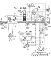
- FIG. 2 is a schematic view showing a port cargo handling apparatus according to an embodiment of the present invention.
- FIG. 3 is a schematic diagram showing a port cargo handling equipment control device and a supplementary control device according to an embodiment of the present invention.
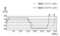
- FIG. 4 is a graph showing the relationship between the speed and time in the cargo handling work of the port cargo handling equipment according to the embodiment of the present invention, and shows the case where the means for shortening the cargo handling time is used and the case where it is not used.
- FIG. 1 is a side view showing a port cargo handling apparatus according to an embodiment of the present invention.
- FIG. 2 is a schematic view showing a port cargo handling apparatus according to an embodiment of the present invention.
- FIG. 3 is a schematic diagram showing a port cargo handling equipment control device and a supplementary control device according to an embodiment of the present invention.
- FIG. 4 is a graph showing the relationship between the speed and time in the
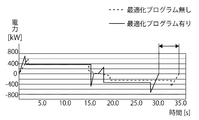
- FIG. 5 is a graph showing the relationship between power consumption and time in the cargo handling work of the port cargo handling equipment according to the embodiment of the present invention, and shows the case where the means for shortening the cargo handling time is used and the case where it is not used.
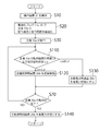
- FIG. 6 shows the flowchart which showed the 1st process of the control method of the harbor handling equipment of embodiment which concerns on this invention.
- FIG. 7 shows the flowchart which showed the 2nd process of the control method of the harbor cargo handling equipment of embodiment which concerns on this invention.
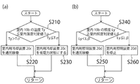
- FIG. 8 shows the flowchart which showed the 3rd process of the control method of the harbor cargo handling equipment of embodiment which concerns on this invention, (a) shows the control method of the indoor cooling device, (b) is indoor lighting The control method of an apparatus is shown.
- a quay crane that travels along a quay as a port cargo handling device and performs cargo handling on a ship will be described as an example.
- a port cargo handling device to which the present invention can be applied is a quay crane. Not limited. For example, it can be applied to harbor handling equipment such as a quay crane, a portal yard crane, a Goliath crane, a jib crane, a tower crane, an unloader crane, an overhead crane, and a straddle carrier.
- the main engine is a device that operates when the main operation (including cargo handling work and traveling) of the port cargo handling equipment is performed.
- a traveling motor for traveling the port cargo handling equipment or a port cargo handling equipment can handle containers.
- a driving device such as a main winding motor for hoisting and lowering
- a device operated by the driving device such as a lifting tool.
- a power supply device that supplies power to these motors is also included.
- a room means a machine room where a main engine is installed, a driver's cab where a driver is boarded, and the like.
- Auxiliary equipment refers to equipment other than the above-mentioned main machine, and is not directly related to the cargo handling operation of harbor handling equipment, but is an apparatus that assists the operation of the main machine or assists to safely perform the main operation.
- a cooling device such as a cooling fan that cools the main winding motor, or a lighting device such as a projector that illuminates the cargo handling operating range, and the operating status (temperature during operation or illuminance of the operating range) or indoor status ( It is a device that optimally maintains the room temperature and the room illuminance.
- the main machine 10a is shown when the main machine is shown
- the indoor 10b is shown when the whole room is shown
- the auxiliary machine 20 is shown when the auxiliary machine is shown
- the main machine 10a is cooled in the auxiliary machine 20.
- the apparatus is the main unit cooling apparatus 20a
- the apparatus that illuminates the operating range of the main apparatus 10a is the cargo handling illuminating apparatus 20b
- the apparatus that cools the interior 10b is the indoor cooling apparatus 20c
- the apparatus that illuminates the interior 10b is the indoor illumination apparatus 20d.
- a port cargo handling device (quay crane) according to an embodiment of the present invention will be described with reference to FIGS.
- a quay crane 1 for handling a ship S includes a boom 2, a girder 3, a trolley 4, a hanger 5, a leg structure 8, and a traveling device 9, and a cab as an interior 10 b. 6 and a machine room 7a (including an electric room 7b).
- the quay crane 1 includes a cable reel 11, a converter 12, an inverter 13, a main winding motor 14, a drum 15, a traverse motor 16, and a traveling motor 17 as a main machine 10a.
- the main motor cooling device 20a includes a main motor cooling fan 23 and a transverse motor cooling fan 24.
- the indoor cooling device 20c includes a mechanical room ventilation fan 21, an electric room air conditioning device 22, and A cab air conditioner 25 is provided.
- the cargo handling lighting device 20b is provided with projectors 27, 28a to 28c, and 29, and the indoor lighting device 20d is provided with a cab interior light 26.
- the cargo handling operation range illuminated by the cargo handling lighting device 20b in the case of the quay crane 1, a range A1 in which the lifting tool 5 operates is shown.
- the cargo handling operation range A1 is illuminated by the projector 27 and the projector 28a so that the operation of the hanger 5 can be confirmed from the cab 6.
- the cargo handling operation range includes a range in which the trolley 4 traverses.
- the main unit cooling device 20a, the cargo handling lighting device 20b, the indoor cooling device 20c, and the indoor lighting device 20d are consumed in addition to normal operation (drive and stop).
- a device capable of reducing power consumption (power saving state) is used.
- the cooling fan 23 for the main winding motor a fan that can be rotated at a low speed that is slower than the normal operation is used, and in the case of the driving room light 26, the light can be dimmed by dimming.
- the present invention is not limited to this, and can also be applied to the auxiliary machine 20 that can only control operation or stop.
- the above-described configuration will be described as an example.
- the present invention is not limited to the above-described configuration, and a well-known crane can be used.
- the thing which mounted the diesel engine in the traveling apparatus 9 the thing which used the storage battery as motive power, etc. can be used.
- you may provide the motor which raises / lowers the boom 2 which is not shown in figure.
- room lights may be provided in the machine room 7a and the electric room 7b.
- the quay crane 1 includes an auxiliary machine control device 31 in the control device 30 as shown in FIG. 3 in addition to the above configuration. And when driving the quay crane 1, the operation signal is sent from the operation device 32 provided in the cab 6 to the control device 30, the control signal is sent from the control device 30 to the inverter 13, and the main machine 10a is operated. Further, temperature sensors 33a to 33e connected to the control device 30 and illuminance sensors 34a to 34f are provided.
- the control device 30 includes a communication unit and a storage unit like a personal computer, and controls the operation of the main unit 10a.
- the control device 30 is provided in the electric room 7b. However, it may be provided in a management wing of the container terminal (not shown) or the operation room 6.
- the auxiliary machine control device 31 When the operation state of the main unit 10a (the temperature of the main unit in operation or the illuminance of the cargo handling operation range) or the indoor state (indoor temperature or indoor illuminance) satisfies the predetermined power reduction condition, the auxiliary machine control device 31 This is a device that puts the auxiliary machine 20 that has maintained the operating state or the indoor state into a power saving state, and is incorporated in the control device 30 as a program.
- the auxiliary machine control device 31 is provided in the control device 30, but may be provided separately from the control device 30, or may be provided in another place such as the cab 6.
- the power saving state referred to here is either a state in which the auxiliary machine 20 is stopped or a state in which the auxiliary machine 20 is operated with lower power than that during normal operation (also referred to as low power driving). This is a state in which less power is consumed than during normal operation.
- the temperature sensors 33a to 33e are well-known temperature sensors, the temperature sensor 33a is the temperature in the machine chamber 7a, the temperature sensor 33b is the temperature of the main winding motor 14, and the temperature sensor 33c is the temperature in the electric chamber 7b.
- the temperature sensor 33d detects the temperature of the traversing motor 16, and the temperature sensor 33e detects the temperature in the cab 6.
- the illuminance sensors 34a to 34f are well-known illuminance sensors, the illuminance sensor 34a is the illuminance in the cab 6, and the illuminance sensor 34b is a range for lifting and lowering the suspension 5 below the cab 6 (loading operation range).
- the illuminance sensors 34c to 34e detect the illuminance in the traversing range (loading operation range) of the trolley 4 below the boom 2 or the girder 3, and the illuminance sensor 34f detects the illuminance above the leg structure 8. ing.
- the quay crane 1 having the above-described configuration When the quay crane 1 having the above-described configuration is in operation of the quay crane 1 and the operation state of the main machine 10a or the condition of the room 10b satisfies a predetermined power reduction condition, the operation condition of the main machine 10a or the condition of the room 10b.
- the auxiliary machine 20 is maintained in a power saving state that consumes less power than during normal operation, and the power consumption of the quay crane 1 can be reduced.
- This quay crane 1 receives electric power from the cable reel 11, and distributes electric power to each apparatus from the inverter 13 provided in the electrical chamber 7b. Then, by operating the operation device 32, the control device 30 controls the inverter 13, thereby driving the traversing motor 16 to traverse the trolley 4, driving the main winding motor 14 and rotating the drum 15, 5 is driven up and down, and the traveling motor 17 is driven to travel the quay crane 1.
- the machine room ventilation fan 21, the electric room air conditioner 22, the main winding motor cooling fan 23, the transverse motor cooling fan 24, and the cab air conditioner 25 are also operated to cool the main machine 10a or the room 10b. .
- the projector 27 that is the cargo handling lighting device 20b , 28a-28c, and 29.
- Auxiliary machine 20 is not limited to the above type as long as it is a device that is not involved in the main operation of quay crane 1.
- the quay crane 1 is configured to raise and lower the boom 2, a fan that cools the drive motor, a cooling fan when the traveling motor 17 that is self-cooling in this embodiment is cooled, etc. Including.
- the sensor which considered the role which the auxiliary machine assists shall be used simultaneously.
- the control device 30 includes an optimization program 35 in addition to the auxiliary machine control device 31.
- the auxiliary machine control device 31 includes a first means (process) 36, a second means (process) 37, and a third means (process) 38.
- the temperature sensors 33a to 33e are integrated to form the temperature sensor 33 and the illuminance sensors 34a to 34f as the illuminance sensor 34.
- the arrows in the figure indicate the signal flow.
- the operation of the main unit 10a described above is performed by the operation unit 32, and the operation of the main unit 10a by the operation, specifically, the operation speed and operation path of the main unit 10a are optimized by the optimization program 35 of the control unit 30, and the main unit 10a is actually operated. Optimization using the optimization program 35 may be performed in advance to control the operation speed and operation path of each main machine 10a.
- the optimization program 35 has at least a shortening of the cargo handling time as an objective function, and the rotational speed, rotational acceleration, and rotational deceleration of the main winding motor 14 and the traversing motor 16, or the operation of the trolley 4 and the lifting tool 5.
- This is a program in which a route (for example, the traverse distance in the case of the trolley 4 and the length of the hoisting and lowering in the case of the lifting tool 5) is a variable, and the variable is optimized using a genetic algorithm.
- Genetic algorithm is an optimal solution search method that mimics the evolutionary process of living organisms. For example, a new solution candidate is generated from an existing solution by two operations, crossover and mutation, and the idea of natural selection. This is a method of searching for an optimal solution by selecting a solution based on the above and repeating generation changes.
- the time required for hoisting and lowering the hoisting tool 5 by setting the rotational acceleration and the rotational deceleration before reaching the maximum hoisting and lowering speed can be large. Optimization can be used to shorten In addition, it is possible to use optimization that makes the hoisting / lowering length of the hanger 5 or the traversing distance of the trolley 4 accurate and does not wastefully operate.
- the main machine 10a By operating the main machine 10a with the above-described optimization program 35, the main machine 10a operates with the optimized operation speed and operation path, so the cargo handling time can be shortened.
- control device 30 is provided with means for stopping the main machine 10a when the loading work by the main machine 10a is completed, the loading work of the quay crane 1 is shortened and consumed in the reduced time. Since electric power can be reduced, the quay crane 1 with less power consumption can be provided.
- the example in which the operation speed and operation path of the main engine 10a are optimized by the optimization program 35 has been described.
- the gripping capacity of the bucket is set. You may optimize.
- the power consumed by the quay crane 1 can be reduced by stopping the auxiliary machine 20 by an amount corresponding to the shortened cargo handling time. This is because the auxiliary machine 20 that was normally operating for the shortened amount can be stopped by the auxiliary machine control device 31, and the power consumption is reduced accordingly.
- the auxiliary machine control device 31 will be described.
- a method for the auxiliary machine control device 31 to operate, stop, or put the auxiliary machine 20 into a power saving state a method of sending a control signal to the inverter 13 and controlling the supplied power is used.
- the temperature of the main machine 10a is Tx
- the temperature of the room 10b is Ty
- the illuminance of the cargo handling operation range is Lx
- the illuminance of the room 10b is Ly
- the first main machine temperature judgment value is T ⁇
- the second main machine temperature judgment value Is T ⁇
- the indoor temperature determination value is T ⁇
- the main machine illuminance determination value is L ⁇
- the indoor illuminance determination value is L ⁇ .
- the first means 36 determines that the power reduction condition is satisfied when the temperature Tx of the main unit 10a is equal to or lower than a predetermined first main unit temperature determination value T ⁇ , and the main unit cooling device 20a When the main machine 10a is not operating and the temperature Tx of the main machine 10a falls below a predetermined second main machine temperature judgment value T ⁇ , it is determined that the power reduction state is satisfied, and the main machine cooling device 20a Is a means for putting the power into a power saving state.
- the main motor cooling fan 23 is set to low power. Operate (rotate at low speed) or stop.
- the main motor cooling fan 23 is operated.
- the main winding motor cooling fan 23 is turned on. Operate with low power (rotate at low speed) or stop.
- the second means 37 determines that the power reduction condition is satisfied when the illuminance Lx in the cargo handling operation range is equal to or greater than a predetermined main unit illuminance determination value L ⁇ , and the lighting device 20b for cargo handling is used.
- the projector 27 when the illumination range of the projector 27 detected by the illuminance sensor 34b, that is, the illuminance Lx of the cargo handling operation range of the suspension 5 becomes higher than the main unit illuminance determination value L ⁇ during the operation of the suspension tool 5, the projector 27 is changed. Operate (reduce) or stop at low power. On the other hand, when the illuminance Lx becomes lower than the main machine illuminance determination value L ⁇ , the projector 27 is operated. Further, after the operation of the hanger 5 is completed, the light projector 27 is dimmed or stopped.
- the third means 38 assumes that the power reduction condition is satisfied when the indoor temperature Ty of the room 10b is equal to or lower than a predetermined indoor temperature determination value T ⁇ , and that the electric power is generated when the indoor illuminance Ly is equal to or higher than a predetermined indoor illuminance determination value L ⁇ . This is means for putting the indoor cooling device 20c and the indoor lighting device 20d into a power saving state when the reduction condition is satisfied.
- the machine room ventilation fan 21 is driven at a low speed or stopped.
- the room illuminance Ly detected by the illuminance sensor 34a provided in the cab 6 becomes equal to or greater than the room illuminance determination value L ⁇ , the cab interior light 26 is dimmed or stopped.
- the auxiliary machine 20 of the quay crane 1 is stopped using the first means 36 to the third means 38 described above, but the operation of the main machine 10a is not limited during the operation of the quay crane 1.
- the auxiliary machine 20 can be stopped within a range in which the main machine 10a operates safely, for example, if the main machine 10a stops, a power saving condition is satisfied and a means for putting the auxiliary machine 20 into a power saving state is provided. Also good.
- the driver operates the operating device 32 (step S10).
- the operation signal input to the operation device 32 is transmitted to the control device 30, and the control device 30 performs an optimization process.
- This optimization process is a process of optimizing the operation speed and the operation path of the main machine 10a by the optimization program 35 (step S20).
- the operation speed and the operation path of the main machine 10a are optimized using a genetic algorithm whose objective function is to at least shorten the cargo handling time.
- the objective function is added so as to suppress the rise in the temperature of the main machine 10a in the optimization process of step S20, the rise in the temperature of the main machine 10a can be suppressed, so that for the main machine during the operation of the main machine 10a.
- the stop time of the cooling device 20a can be extended, and power consumption can be further reduced.
- step S20 may be performed in advance, the optimized operation speed and operation route of the main machine 10a may be stored in the control device 30, and read according to the operation of the operation device 32.
- step S30 when the main device 10a is operated by the control device 30 (step S30), the temperature sensor 33 detects the temperature Tx of the main device 10a, and the auxiliary device control device 31 detects that the temperature Tx of the main device 10a is the first. It is determined whether or not the temperature is lower than the main engine temperature determination value T ⁇ (step S40).
- step S40 If it is determined in step S40 that the temperature Tx of the main machine 10a is higher than the first main machine temperature determination value T ⁇ , then the auxiliary machine control device 31 normally operates the main machine cooling device 20a (step S50). Thereby, main machine 10a can be cooled and temperature Tx of main machine 10a can be prevented from rising excessively.
- step S40 determines that the temperature Tx of the main machine 10a is equal to or lower than the first main machine temperature determination value T ⁇ .
- the auxiliary machine control device 31 puts the main machine cooling device 20a into the power saving state (step S60).
- step S60 it is possible to suppress excessive cooling of the main unit 10a, and to reduce the power consumed by the main unit cooling device 20a.
- Steps S40 to S60 are processes performed by constantly monitoring the temperature Tx of the main machine 10a until the operation of the main machine 10a is completed, and may be performed at predetermined time intervals.
- step S70 the control device 30 determines whether or not the operation of the main unit 10a is completed.
- step S70 the operation of the main unit 10a is completed based on the operation signal of the operation device 32, and the control device 30 performs the main unit stop process, and determines that the operation of the main unit 10a is completed when the main unit 10a is stopped.
- the temperature sensor 33 detects the temperature Tx after the main machine 10a is stopped, and the auxiliary machine control device 31 determines whether or not the temperature Tx of the main machine 10a is equal to or lower than the second main machine temperature determination value T ⁇ (step S80). If it is determined that the temperature Tx of the main machine 10a is higher than the second main machine temperature determination value T ⁇ , then the main machine cooling device 20a is normally operated (step S90), and the process returns to step S80. On the other hand, if it is determined in step S80 that the temperature Tx of the main machine 10a is equal to or lower than the second main machine temperature determination value T ⁇ , then the main machine cooling device 20a is put into a power saving state (step S100). Thus, the control method of the main unit cooling device 20a is completed.
- the first main machine temperature judgment value T ⁇ and the second main machine temperature judgment value T ⁇ can be arbitrarily set, and may be set to values that can prevent the main machine 10a from being heated excessively.
- the first main machine temperature determination value T ⁇ and the second main machine temperature determination value T ⁇ are set separately, and the second main machine temperature determination value T ⁇ is set high enough to be the first main machine temperature determination value T ⁇ . Then, when the main machine 10a is not operating (after the main machine 10a is stopped), since there is no subsequent heating, loss of power due to excessive cooling can be prevented.
- the main machine cooling device 20a can be put into a power saving state, and therefore the main machine 10a is excessively cooled. Since the power consumed by the main unit cooling device 20a can be reduced, the energy consumption of the quay crane 1 can be reduced.
- the main machine 10a since the operation speed and operation path of the main machine 10a are optimized using the optimization program 35, the main machine 10a is stopped earlier than the operation of the main machine 10a not using the optimization program 35, and the main machine 10a is used accordingly. Since the cooling device 20a can also be brought into a power saving state quickly, power consumption can be reduced.
- the traversing motor 16 is driven by the operation signal of the operating device 32 to traverse the trolley 4.
- the traverse motor cooling fan 24 is driven to cool the traverse motor 16.
- the traverse motor cooling fan 24 is rotated at a lower speed than usual so as to be in a power saving state.
- the traversing motor 16 is stopped and the trolley 4 is stopped.
- the traverse motor cooling fan 24 is stopped.
- the transverse motor cooling fan 24 can be stopped, and power consumption can be reduced accordingly.
- steps S10 to S30 the illuminance sensor 34 detects the illuminance Lx in the cargo handling operation range, and the auxiliary equipment control device 31 determines whether the illuminance Lx in the cargo handling operation range is greater than or equal to the main machine illuminance determination value L ⁇ . Is determined (step S110).
- step S110 If it is determined in step S110 that the illuminance Lx is smaller than the main machine illuminance determination value L ⁇ , then the auxiliary equipment control device 31 normally operates the cargo handling lighting device 20b (step S120). Thereby, before a cargo handling operation
- step S110 determines whether the illuminance Lx is greater than or equal to the main machine illuminance determination value L ⁇ . If it is determined in step S110 that the illuminance Lx is greater than or equal to the main machine illuminance determination value L ⁇ , the cargo handling lighting device 20b is then placed in a power saving state (step S130). By this step S130, it is possible to suppress excessively brightening the cargo handling operation range, and to reduce the power consumed by the cargo handling lighting device 20b.
- Steps S110 to S130 are steps performed by constantly monitoring the illuminance Lx in the operation range of the main unit 10a until the operation of the main unit 10a is completed, and may be performed every predetermined time. .
- step S70 the control device 30 determines whether or not the operation of the main unit 10a is completed.
- step S70 from the operation signal of the operation device 32, the operation of the main machine 10a is completed, and when the control device 30 performs the main machine stop process and stops the main machine 10a, it is determined that the operation of the main machine 10a is completed. If it is determined that the operation of the main machine 10a is completed, the cargo handling lighting device 20b is then set in a power saving state (step S140). The control method of the cargo handling lighting device 20b is thus completed.
- the lighting device 20b for cargo handling before the operation of the main unit 10a, the lighting device 20b for cargo handling can be brought into a power saving state by the illuminance Lx in the operation range of the main unit 10a, and immediately after the main unit 10a stops, Since the cargo handling lighting device 20b can be brought into a power saving state, the power consumed by the cargo handling lighting device 20b that does not need to be operated can be reduced, and the energy consumption of the quay crane 1 can be reduced.
- the main machine 10a since the operation speed and operation path of the main machine 10a are optimized using the optimization program 35, the main machine 10a can be stopped earlier than the operation of the main machine 10a without using the optimization program 35. Therefore, power consumption can be reduced accordingly.
- the projector 27 is activated when the illuminance Lx in the cargo handling operation range detected by the illuminance sensor 34b installed below the cab 6 becomes smaller than the main machine illuminance determination value L ⁇ .
- the hoisting device 5 starts to be wound up and down.
- the illuminance Lx becomes equal to or greater than the main machine illuminance determination value L ⁇ during the operation of the hanger 5, the light projector 27 is dimmed and dimmed.
- the main winding motor 14 is stopped.
- the projector 27 is stopped. Thereby, the light projector 27 used for confirming the hoisting / lowering operation of the hanger 5 can be stopped when the hanger 5 is not used, and the power consumption can be reduced correspondingly.
- the illuminance sensors 34c to 34e that detect the irradiation ranges of the plurality of projectors 28a to 28c under the boom 2 or the girder 3 indicate that the irradiation ranges of the respective projectors 28a to 28c are shadows of the trolley 4. It may be detected and the projector that becomes the shadow of the trolley 4 may be turned off to reduce power consumption accordingly.
- step S210 it is determined whether or not the room temperature Ty of the room 10b is equal to or lower than the room temperature judgment value T ⁇ (step S210), and the room temperature judgment value T ⁇ . If it is determined that the temperature is higher than that, the auxiliary device control device 31 normally operates the indoor cooling device 20c (step S220). On the other hand, if the indoor temperature Ty is determined to be equal to or less than the indoor temperature determination value T ⁇ , the auxiliary device control device 31 performs the indoor operation. The cooling device 20c is put into a power saving state (step S230).
- step S240 it is determined whether or not the room illuminance Ly in the room 10b is equal to or greater than the room illuminance determination value L ⁇ (step S240). If it is determined that the value is smaller than the value L ⁇ , the auxiliary device control device 31 normally operates the indoor lighting device 20d (step S250). On the other hand, if it is determined that the indoor illuminance Ly is greater than or equal to the indoor illuminance determination value L ⁇ , the auxiliary device control device 31. Sets the indoor lighting device 20d in the power saving state (step S260).
- control method described above can be applied to the cab air conditioner 25 and the cab light 26 in the cab 6.
- a sensor for detecting that a driver or an inspector enters the room 10b is provided, and when the sensor detects entering / exiting the room 10b, the indoor cooling device 20c and the indoor lighting device 20d are operated. Good.
- the port handling equipment of the present invention can reduce the power consumed by the auxiliary equipment by controlling auxiliary equipment other than the main equipment that performs the main operation separately from the operation of the main equipment. Consumption can be reduced. Therefore, it can be used as a quay crane or a yard crane with low energy consumption.
Landscapes
- Engineering & Computer Science (AREA)
- Mechanical Engineering (AREA)
- Automation & Control Theory (AREA)
- Warehouses Or Storage Devices (AREA)
- Control And Safety Of Cranes (AREA)
- Ship Loading And Unloading (AREA)
Abstract
Description
2 ブーム
3 ガーター
4 トロリ
5 吊り具
6 運転室
7a 機械室
7b 電気室
8 脚構造物
9 走行装置
10a 主機
10b 室内
11 ケーブルリール
12 コンバータ
13 インバータ
14 主巻モータ
15 ドラム
16 横行モータ
17 草稿モータ
20 補機
20a 主機用冷却装置
20b 荷役用照明装置
20c 室内用冷却装置
20d 室内用照明装置
21 機械室用換気ファン
22 電気室用空調装置
23 主巻モータ用冷却ファン
24 横行モータ用冷却ファン
25 運転室用空調装置
26 運転室内灯
27、28a~28c、29 投光器
30 制御装置
31 補機制御装置
32 操作装置
33 温度センサ
34 照度センサ
35 最適化プログラム
36 第1手段(第1工程)
37 第2手段(第2工程)
38 第3手段(第3工程)
Claims (8)
- 港湾荷役機器の主要動作を行う主機以外の装置であり、前記主機を冷却する主機用冷却装置、荷役動作範囲を照らす荷役用照明装置、前記港湾荷役機器の室内を冷却する室内用冷却装置、及び前記室内を照らす室内用照明装置を含む補機を備える港湾荷役機器の制御方法において、
前記港湾荷役機器の運転中に、前記主機の動作状況、又は室内状況が予め定めた電力削減条件を満たすと、前記主機の動作状況、又は前記室内状況を維持している前記補機を通常稼働時よりも消費される電力が少ない省電力状態にすることを特徴とする港湾荷役機器の制御方法。 - 前記主機が動作している場合に、前記主機の温度が予め定めた第1主機温度判定値以下になると前記電力削減条件を満たしたとして、前記主機用冷却装置を前記省電力状態にし、
前記主機が動作していない場合に、前記主機の温度が第2主機温度判定値以下になると前記電力削減条件を満たしたとして、前記主機用冷却装置を前記省電力状態にする第1工程と、
前記主機が動作している場合に、前記荷役動作範囲の明るさが予め定めた主機照度判定値以上になると前記電力削減条件を満たしたとして、前記荷役用照明装置を前記省電力状態にし、
前記主機が動作していない場合に、前記電力削減条件を満たしたとして、前記荷役用照明装置を前記省電力状態にする第2工程と、の少なくともどちらか一方を含む請求項1に記載の港湾荷役機器の制御方法。 - 前記主機の動作速度と動作経路とを、少なくとも荷役時間の短縮を目的関数とする遺伝的アルゴリズムを用いて最適化する最適化工程と、
前記最適化工程で最適化された前記動作速度と前記動作経路で前記主機を動作し、荷役動作の完了後に、前記主機を停止する主機停止工程と、を含むことを特徴とする請求項2に記載の港湾荷役機器の制御方法。 - 前記港湾荷役機器の運転中に、前記室内の温度が予め定めた室内温度判定値以下になると前記電力削減条件を満たしたとして、前記室内用冷却装置を前記省電力状態にし、
前記室内の明るさが予め定めた室内照度判定値以上になると前記電力削減条件を満たしたとして、前記室内用照明装置を前記省電力状態にする第3工程を含むことを特徴とする請求項1~3のいずれか1項に記載の港湾荷役機器の制御方法。 - 港湾荷役機器の主要動作を行う主機以外の装置であり、前記主機を冷却する主機用冷却装置、荷役動作範囲を照らす荷役用照明装置、前記港湾荷役機器の室内を冷却する室内用冷却装置、及び前記室内を照らす室内用照明装置を含む補機を備える港湾荷役機器において、
前記港湾荷役機器の運転中に、前記主機の動作状況、又は室内状況が予め定めた電力削減条件を満たすと、前記主機の動作状況、又は前記室内状況を維持している前記補機を通常稼働時よりも消費される電力が少ない省電力状態にする補機制御装置を備えることを特徴とする港湾荷役機器。 - 前記補機制御装置が、
前記主機が動作している場合に、前記主機の温度が予め定めた第1主機温度判定値以下になると前記電力削減条件を満たしたとして、前記主機用冷却装置を前記省電力状態にし、
前記主機が動作していない場合に、前記主機の温度が第2主機温度判定値以下になると
前記電力削減条件を満たしたとして、前記主機用冷却装置を前記省電力状態にする第1手段と、
前記主機が動作している場合に、前記荷役動作範囲の明るさが予め定めた主機照度判定値以上になると前記電力削減条件を満たしたとして、前記荷役用照明装置を前記省電力状態にし、
前記主機が動作していない場合に、前記電力削減条件を満たしたとして、前記荷役用照明装置を前記省電力状態にする第2手段と、の少なくともどちらか一方を備えることを特徴とする請求項5に記載の港湾荷役機器。 - 前記主機の動作を制御する制御装置を備えると共に、
前記制御装置が、前記主機の動作速度と動作経路とを、少なくとも荷役時間の短縮を目的関数とする遺伝的アルゴリズムを用いて最適化する最適化プログラムと、
前記最適化プログラムを用いて最適化された前記動作速度と前記動作経路で前記主機を動作し、荷役動作の完了後に、前記主機を停止する主機停止手段と、を備えることを特徴とする請求項6に記載の港湾荷役機器。 - 前記補機制御装置が、前記港湾荷役機器の運転中に、前記室内の温度が予め定めた室内温度判定値以下になると前記電力削減条件を満たしたとして、前記室内用冷却装置を前記省電力状態にし、
前記室内の明るさが予め定めた室内照度判定値以上なると前記電力削減条件を満たしたとして、前記室内用照明装置を前記省電力状態にする第4手段を備えることを特徴とする請求項5~7のいずれか1項に記載の港湾荷役機器。
Priority Applications (2)
| Application Number | Priority Date | Filing Date | Title |
|---|---|---|---|
| US14/779,120 US9745174B2 (en) | 2013-03-26 | 2013-03-28 | Method for controlling port loading and unloading apparatus and port loading and unloading apparatus |
| CN201380075118.4A CN105073622B (zh) | 2013-03-26 | 2013-03-28 | 港口货物装卸设备的控制方法和港口货物装卸设备 |
Applications Claiming Priority (2)
| Application Number | Priority Date | Filing Date | Title |
|---|---|---|---|
| JP2013063727A JP5989584B2 (ja) | 2013-03-26 | 2013-03-26 | 港湾荷役機器の制御方法と港湾荷役機器 |
| JP2013-063727 | 2013-03-26 |
Publications (1)
| Publication Number | Publication Date |
|---|---|
| WO2014155598A1 true WO2014155598A1 (ja) | 2014-10-02 |
Family
ID=51622673
Family Applications (1)
| Application Number | Title | Priority Date | Filing Date |
|---|---|---|---|
| PCT/JP2013/059225 Ceased WO2014155598A1 (ja) | 2013-03-26 | 2013-03-28 | 港湾荷役機器の制御方法と港湾荷役機器 |
Country Status (4)
| Country | Link |
|---|---|
| US (1) | US9745174B2 (ja) |
| JP (1) | JP5989584B2 (ja) |
| CN (1) | CN105073622B (ja) |
| WO (1) | WO2014155598A1 (ja) |
Families Citing this family (3)
| Publication number | Priority date | Publication date | Assignee | Title |
|---|---|---|---|---|
| CN107678407A (zh) * | 2017-08-28 | 2018-02-09 | 鑫鹏源智能装备集团有限公司 | 节能管理装置及系统 |
| US20240391741A1 (en) * | 2021-09-24 | 2024-11-28 | Paccar Inc | Stand-alone electronic control of winches |
| JP2023111358A (ja) * | 2022-01-31 | 2023-08-10 | Ihi運搬機械株式会社 | 運搬機械の省エネルギ運転促進システム |
Citations (8)
| Publication number | Priority date | Publication date | Assignee | Title |
|---|---|---|---|---|
| JPS58104890A (ja) * | 1981-12-11 | 1983-06-22 | 石川島播磨重工業株式会社 | 荷役機械の消費電力制御装置 |
| JPH07304385A (ja) * | 1994-05-10 | 1995-11-21 | Hitachi Constr Mach Co Ltd | 建設機械の照明装置 |
| JP2004326201A (ja) * | 2003-04-21 | 2004-11-18 | Mitsubishi Heavy Ind Ltd | 自動機械、及び、機械の自動化装置 |
| JP2005127618A (ja) * | 2003-10-24 | 2005-05-19 | Hitachi Ltd | 空調機の集中管理システム |
| JP2008253114A (ja) * | 2007-03-30 | 2008-10-16 | Mitsui Eng & Shipbuild Co Ltd | モータ駆動方法、装置、およびクレーン装置 |
| JP2010160975A (ja) * | 2009-01-08 | 2010-07-22 | Sky Planning:Kk | 屋内照明装置 |
| JP2012188208A (ja) * | 2011-03-09 | 2012-10-04 | Toshiba Elevator Co Ltd | エレベータシステム |
| JP2012232829A (ja) * | 2011-05-02 | 2012-11-29 | Mitsui Eng & Shipbuild Co Ltd | 消費電力を低減することができるクレーンとその消費電力削減方法と消費電力を表示するプログラム |
Family Cites Families (12)
| Publication number | Priority date | Publication date | Assignee | Title |
|---|---|---|---|---|
| US5814955A (en) * | 1997-03-14 | 1998-09-29 | Eaton Corporation | Motor control circuit with a low voltage monitor |
| JP4616447B2 (ja) | 2000-07-31 | 2011-01-19 | 三菱重工業株式会社 | クレーンおよびクレーン制御方法 |
| CN100408466C (zh) * | 2006-01-27 | 2008-08-06 | 上海振华港口机械(集团)股份有限公司 | 轮胎式龙门集装箱起重机的节能控制系统 |
| WO2008043244A1 (en) * | 2006-09-18 | 2008-04-17 | Qinfen He | Power supplying equipment from electric supply network for rubber-tired crane in port |
| CN101229883A (zh) * | 2008-01-24 | 2008-07-30 | 上海振华港口机械(集团)股份有限公司 | 集装箱码头装卸系统 |
| US8234046B2 (en) * | 2009-02-25 | 2012-07-31 | Rs Drawings, Llc | Method and apparatus for selectively activated powered actuation of a hydraulic drive system |
| CN201412229Y (zh) * | 2009-05-05 | 2010-02-24 | 上海国际港务(集团)股份有限公司 | 轮胎吊发动机调速节能装置 |
| MY154760A (en) * | 2009-06-16 | 2015-07-15 | Sumitomo Heavy Ind Engineering And Services Co Ltd | Hybrid electric power device for crane and control method of hybrid electric power device for crane |
| JP2012180053A (ja) * | 2011-03-02 | 2012-09-20 | Toyota Motor Corp | 車両用空調制御装置 |
| JP5633972B2 (ja) * | 2011-03-31 | 2014-12-03 | 三井造船株式会社 | クレーン装置 |
| JP6027790B2 (ja) * | 2012-06-29 | 2016-11-16 | 株式会社タダノ | 作業車両 |
| CN102887434B (zh) * | 2012-10-19 | 2014-07-02 | 青岛港(集团)有限公司 | 一种节能型轮胎吊 |
-
2013
- 2013-03-26 JP JP2013063727A patent/JP5989584B2/ja active Active
- 2013-03-28 CN CN201380075118.4A patent/CN105073622B/zh not_active Expired - Fee Related
- 2013-03-28 US US14/779,120 patent/US9745174B2/en not_active Expired - Fee Related
- 2013-03-28 WO PCT/JP2013/059225 patent/WO2014155598A1/ja not_active Ceased
Patent Citations (8)
| Publication number | Priority date | Publication date | Assignee | Title |
|---|---|---|---|---|
| JPS58104890A (ja) * | 1981-12-11 | 1983-06-22 | 石川島播磨重工業株式会社 | 荷役機械の消費電力制御装置 |
| JPH07304385A (ja) * | 1994-05-10 | 1995-11-21 | Hitachi Constr Mach Co Ltd | 建設機械の照明装置 |
| JP2004326201A (ja) * | 2003-04-21 | 2004-11-18 | Mitsubishi Heavy Ind Ltd | 自動機械、及び、機械の自動化装置 |
| JP2005127618A (ja) * | 2003-10-24 | 2005-05-19 | Hitachi Ltd | 空調機の集中管理システム |
| JP2008253114A (ja) * | 2007-03-30 | 2008-10-16 | Mitsui Eng & Shipbuild Co Ltd | モータ駆動方法、装置、およびクレーン装置 |
| JP2010160975A (ja) * | 2009-01-08 | 2010-07-22 | Sky Planning:Kk | 屋内照明装置 |
| JP2012188208A (ja) * | 2011-03-09 | 2012-10-04 | Toshiba Elevator Co Ltd | エレベータシステム |
| JP2012232829A (ja) * | 2011-05-02 | 2012-11-29 | Mitsui Eng & Shipbuild Co Ltd | 消費電力を低減することができるクレーンとその消費電力削減方法と消費電力を表示するプログラム |
Also Published As
| Publication number | Publication date |
|---|---|
| US20160046466A1 (en) | 2016-02-18 |
| JP5989584B2 (ja) | 2016-09-07 |
| CN105073622A (zh) | 2015-11-18 |
| CN105073622B (zh) | 2019-03-08 |
| JP2014189349A (ja) | 2014-10-06 |
| US9745174B2 (en) | 2017-08-29 |
Similar Documents
| Publication | Publication Date | Title |
|---|---|---|
| CN101595028B (zh) | 控制装置 | |
| JP5989584B2 (ja) | 港湾荷役機器の制御方法と港湾荷役機器 | |
| CN103443016A (zh) | 起重机和用于使用从起重机操作回收的能量作为次能量源而操作起重机的方法 | |
| WO2008050552A1 (en) | Crane system and its control method | |
| JP2009023817A (ja) | クレーン装置 | |
| JP2011068499A (ja) | クレーン装置 | |
| JP2009023816A (ja) | クレーン装置 | |
| JP5516504B2 (ja) | 荷役システム | |
| WO2012043479A1 (ja) | ハイブリッド式駆動装置、クレーン制御装置、及びクレーン装置 | |
| CN205104981U (zh) | 一种带吊臂装置的电源车 | |
| JP4952656B2 (ja) | 建設機械 | |
| JP4909788B2 (ja) | クレーン装置 | |
| JP5384900B2 (ja) | クレーン装置 | |
| KR20090057877A (ko) | 타이어형 포털 크레인, 타이어형 포털 크레인 시스템, 및타이어형 포털 크레인의 이동 방법 | |
| WO2011065180A1 (ja) | クレーン制御装置及びクレーン装置 | |
| CN220673984U (zh) | 一种岸桥智能照明系统 | |
| JP5820226B2 (ja) | クレーン | |
| CN219507499U (zh) | 一种岸桥吊具的智能补光系统及岸桥 | |
| JP2013018641A (ja) | 荷役時間を短縮する港湾荷役機器の制御方法と港湾荷役機器 | |
| JP2008254822A (ja) | クレーン装置 | |
| JP2010083639A (ja) | クレーン装置およびクレーン制御方法 | |
| JP2008247589A (ja) | クレーン装置 | |
| KR101814502B1 (ko) | 가정용 전원을 이용한 고가 사다리차의 운반카 이송시스템 및 그 제어방법 | |
| JP4928718B2 (ja) | エンジン発電機付きクレーンの制御方法およびエンジン発電機付きクレーン | |
| JP5412842B2 (ja) | クレーンシステム及びその制御方法 |
Legal Events
| Date | Code | Title | Description |
|---|---|---|---|
| WWE | Wipo information: entry into national phase |
Ref document number: 201380075118.4 Country of ref document: CN |
|
| 121 | Ep: the epo has been informed by wipo that ep was designated in this application |
Ref document number: 13879949 Country of ref document: EP Kind code of ref document: A1 |
|
| WWE | Wipo information: entry into national phase |
Ref document number: 14779120 Country of ref document: US |
|
| NENP | Non-entry into the national phase |
Ref country code: DE |
|
| 122 | Ep: pct application non-entry in european phase |
Ref document number: 13879949 Country of ref document: EP Kind code of ref document: A1 |