WO2014148434A1 - Linear motor - Google Patents
Linear motor Download PDFInfo
- Publication number
- WO2014148434A1 WO2014148434A1 PCT/JP2014/057141 JP2014057141W WO2014148434A1 WO 2014148434 A1 WO2014148434 A1 WO 2014148434A1 JP 2014057141 W JP2014057141 W JP 2014057141W WO 2014148434 A1 WO2014148434 A1 WO 2014148434A1
- Authority
- WO
- WIPO (PCT)
- Prior art keywords
- plate
- linear motor
- moving direction
- mover
- tooth
- Prior art date
Links
Images


Classifications
-
- H—ELECTRICITY
- H02—GENERATION; CONVERSION OR DISTRIBUTION OF ELECTRIC POWER
- H02K—DYNAMO-ELECTRIC MACHINES
- H02K41/00—Propulsion systems in which a rigid body is moved along a path due to dynamo-electric interaction between the body and a magnetic field travelling along the path
- H02K41/02—Linear motors; Sectional motors
-
- H—ELECTRICITY
- H02—GENERATION; CONVERSION OR DISTRIBUTION OF ELECTRIC POWER
- H02K—DYNAMO-ELECTRIC MACHINES
- H02K1/00—Details of the magnetic circuit
- H02K1/06—Details of the magnetic circuit characterised by the shape, form or construction
- H02K1/12—Stationary parts of the magnetic circuit
- H02K1/14—Stator cores with salient poles
-
- H—ELECTRICITY
- H02—GENERATION; CONVERSION OR DISTRIBUTION OF ELECTRIC POWER
- H02K—DYNAMO-ELECTRIC MACHINES
- H02K1/00—Details of the magnetic circuit
- H02K1/06—Details of the magnetic circuit characterised by the shape, form or construction
- H02K1/34—Reciprocating, oscillating or vibrating parts of the magnetic circuit
-
- H—ELECTRICITY
- H02—GENERATION; CONVERSION OR DISTRIBUTION OF ELECTRIC POWER
- H02K—DYNAMO-ELECTRIC MACHINES
- H02K41/00—Propulsion systems in which a rigid body is moved along a path due to dynamo-electric interaction between the body and a magnetic field travelling along the path
- H02K41/02—Linear motors; Sectional motors
- H02K41/03—Synchronous motors; Motors moving step by step; Reluctance motors
- H02K41/031—Synchronous motors; Motors moving step by step; Reluctance motors of the permanent magnet type
- H02K41/033—Synchronous motors; Motors moving step by step; Reluctance motors of the permanent magnet type with armature and magnets on one member, the other member being a flux distributor
Definitions
- the present invention relates to a linear motor formed by combining a stator having salient poles and a mover having coils and magnets.
- a feeding device that can linearly move an object to be processed such as a large-area substrate at a high speed and accurately position the object at an appropriate moving position.
- This type of feeding device is generally realized by converting the rotational motion of a motor as a drive source into a linear motion by a motion conversion mechanism such as a ball screw mechanism, but since a motion conversion mechanism is interposed, There is a limit to increasing the moving speed. There is also a problem that positioning accuracy is insufficient due to the presence of mechanical errors in the motion conversion mechanism.
- the linear motor includes a linear stator and a mover that moves along the stator.
- a moving coil type linear motor (a moving coil type linear motor) in which a large number of plate-like permanent magnets are arranged in parallel at regular intervals to constitute a stator, and an armature having magnetic pole teeth and energizing coils is used as a mover.
- Patent Document 1 is used.
- the thrust waveform per single phase needs to be substantially a sine wave in order to reduce the fluctuation range of the three-phase combined thrust that varies depending on the position of the mover. It is also necessary to ensure thrust.
- the pitch is reduced, the drive frequency is increased, and the iron loss of the linear motor itself is increased.
- the present invention has been made in view of the circumstances as described above, and provides a linear motor that realizes miniaturization and weight reduction of a mover without increasing the amount of magnet used even if the total length of the linear motor is long. With the goal.
- the linear motor according to the present invention is a linear motor including a stator and a mover having a coil.
- the stator has two plate-like portions that are long in the moving direction of the mover. Are arranged opposite each other so as to be magnetically coupled with a moving range of the mover in between, and a plurality of tooth portions are formed on one of the plate-like surfaces on each of the mutually opposing surfaces.
- the tooth part of the part and the tooth part of the other plate-like part are arranged in a staggered manner in the moving direction, and the mover has two magnets in the coil along the moving direction. Three yokes are alternately arranged, the two magnets are magnetized along the moving direction, and the magnetization directions oppose each other.
- the mover has a minimum configuration including two magnets and three yokes. Therefore, even if the pitch of the teeth on the stator side is relatively large, the dimension in the moving direction of the mover. Can be made smaller. In other words, it can be said that the pitch of the teeth on the stator side is relatively easy to increase. In addition, since no magnet is used for the stator, the amount of magnet used does not increase even when the total length of the linear motor is long.
- the linear motor according to the present invention is characterized in that a yoke sandwiched between the two magnets is longer in the moving direction than the other two yokes.
- the yoke sandwiched between the two magnets is longer in the moving direction than the other two yokes in contact with only one magnet.
- the length in the direction of movement that is, the length of the portion facing the tooth portion is determined according to the amount of magnetic flux exchanged with the magnet, so even if the amount of current flowing through the coil increases, the yoke is less likely to be magnetically saturated. .
- the linear motor according to the present invention is characterized in that the length of the yoke sandwiched between the two magnets in the moving direction is twice as long as the other two yokes.
- the length in the moving direction of the yoke sandwiched between the two magnets is twice as long as the other two yokes that are optimal for the amount of magnetic flux flowing. It is possible to obtain a linear motor having a large thrust by reducing the magnetic saturation of the yoke while reducing the length in the direction.
- the linear motor according to the present invention is characterized in that the width of the tooth portions in the juxtaposed direction is longer than the interval between the tooth portions.
- the width in the juxtaposed direction of the tooth portions is wider than the juxtaposition interval of the tooth portions, it is possible to obtain a larger thrust.
- the two magnets and the three yokes form a rectangular parallelepiped shape, and the surfaces of the magnets and the yokes on the moving direction side are orthogonal to the moving direction and the opposing direction of the plate-like portion. Inclined with respect to the direction.
- the surface on the moving direction side of each magnet and each yoke is inclined in a direction orthogonal to the moving direction and the opposing direction of the plate-like portion.
- the linear motor according to the present invention is characterized in that the tooth portion has a rectangular parallelepiped shape, and any two sides facing each other in a cross section parallel to the plate-like portion of the tooth portion are inclined with respect to the moving direction. To do.
- the tooth portion has a rectangular parallelepiped shape, and any two sides of the tooth portion facing each other in a cross section parallel to the plate-like portion are inclined with respect to the moving direction. That is, since the tooth portions are arranged in a skew manner, the detent force is reduced, and it becomes possible to reduce the thrust unevenness due to the difference in the relative positions of the stator and the mover.
- the linear motor according to the present invention is characterized in that the inclined portions of the two sides of the cross section of the tooth portions of the two plate-like portions are opposite to each other.
- the tooth portions of the two plate-like parts have the two sides of the cross section inclined in opposite directions. That is, since the direction in which the tooth portion is inclined is different between one and the other of the plate-like portions, it is possible to suppress the twisting that occurs when the mover is inclined to the left and right with respect to the moving direction.
- the linear motor according to the present invention includes a plate-like nonmagnetic plate provided between a side surface of the yoke and magnet parallel to the moving direction and the coil, the nonmagnetic plate, the yoke, and the magnet.
- An auxiliary plate made of a plate-like non-magnetic non-conductive material provided opposite to the coil is provided.
- the non-magnetic non-conductive material is provided between the yoke and the coil, the flow path of the eddy current flowing through the yoke is partially blocked, and the eddy current loss can be reduced. Become.
- the linear motor according to the present invention is characterized in that it further includes a connecting portion that is connected to the non-magnetic plate and connects three movers arranged in the moving direction.
- the non-magnetic plate includes plate-like first protruding plate portions and second protruding plate portions facing each other with the coil winding interposed therebetween, the first protruding plate portion, and the It has the base which connects a 2nd protrusion board part, It is characterized by the above-mentioned.
- the thrust of the linear motor can be easily transmitted to the outside.
- the stator since the stator has a minimum configuration including two magnets and three yokes, the dimension of the mover in the moving direction can be further reduced. In addition, since no magnet is used for the stator, there is an effect that the amount of magnet used does not increase even when the linear motor has a long overall length.
- the armature yoke and the yoke used in the present specification and claims are used interchangeably.
- FIG. 1 is a partially broken perspective view showing an example of a schematic configuration of a linear motor according to Embodiment 1.
- FIG. 3 is a plan view illustrating a configuration example of a mover of the linear motor according to Embodiment 1.
- FIG. 1 is a cross-sectional view illustrating a schematic configuration of a linear motor according to a first embodiment.
- 1 is a side view illustrating a schematic configuration of a linear motor according to a first embodiment.
- FIG. 4 is a diagram for explaining the principle of thrust generation of the linear motor according to the first embodiment.
- FIG. 4 is a diagram for explaining the principle of thrust generation of the linear motor according to the first embodiment.
- FIG. 4 is a diagram for explaining the principle of thrust generation of the linear motor according to the first embodiment.
- FIG. 4 is a diagram for explaining the principle of thrust generation of the linear motor according to the first embodiment.
- FIG. 5 is a plan view showing a mover of a linear motor according to Embodiment 2.
- FIG. It is explanatory drawing about the magnetic saturation of the armature yoke of a needle
- FIG. 10 is a plan view illustrating a configuration example of a mover of a linear motor according to Embodiment 3.
- FIG. FIG. 12 is a sectional view showing a section taken along a section line XII-XII in FIG.
- FIG. 10 is a diagram for explaining the operation of the linear motor according to the third embodiment. 10 is a graph showing the thrust of the linear motor according to the third embodiment.
- FIG. 10 is a plan view illustrating a configuration example of a mover of a linear motor according to a fourth embodiment.
- FIG. 10 is a cross-sectional view illustrating a configuration of a stator of a linear motor according to a fifth embodiment.
- FIG. 10 is a cross-sectional view illustrating a configuration of a stator of a linear motor according to a sixth embodiment.
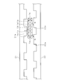
- FIG. 1 is a partially broken perspective view showing an example of a schematic configuration of the linear motor according to the first embodiment.
- FIG. 2 is a plan view showing a configuration example of the mover 1 of the linear motor according to the first embodiment.
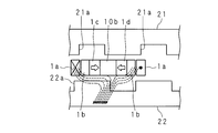
- FIG. 3 is a cross-sectional view showing a schematic configuration of the linear motor according to the first embodiment.
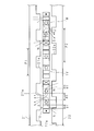
- FIG. 4 is a side view showing a schematic configuration of the linear motor according to the first embodiment.
- the linear motor according to the present embodiment includes a mover 1 and a stator 2.
- the mover 1 has a configuration in which a coil 1a is wound around a substantially rectangular parallelepiped armature yoke (yoke) 1b and permanent magnets (magnets) 1c and 1d.
- the mover 1 has a minimum configuration including three armature yokes 1b and one permanent magnet 1c and 1d. As shown in FIG.
- the armature yoke 1b, the permanent magnet 1c, the armature yoke 1b, the permanent magnet 1d, the armature yoke 1b, and the armature yoke 1b, the permanent magnet 1c or 1d are in the moving direction of the mover 1.
- the permanent magnet 1c and the permanent magnet 1d are arranged so as to sandwich the armature yoke 1b.
- the white arrows shown in the permanent magnets 1c and 1d in FIGS. 2 and 4 indicate the magnetization directions of the permanent magnets 1c and 1d.
- the end point of the white arrow indicates the N pole, and the start point indicates the S pole.
- the permanent magnet 1c and the permanent magnet 1d are magnetized along the moving direction of the mover 1, and the magnetization directions are opposed to each other.
- the coil 1a surrounds the armature yoke 1b and the permanent magnet 1c or 1d arranged as described above.
- the stator 2 has a substantially U-shaped cross section (U shape).
- the stator 2 includes two plate-like portions, an upper plate portion 21 and a lower plate portion 22.
- the upper plate portion 21 and the lower plate portion 22 face each other with the movable element 1 in the moving range.
- the plate-shaped side plate portion 23 connects the upper plate portion 21 and the lower plate portion 22.
- the stator 2 is elongated in the moving direction of the mover 1.
- the upper plate portion 21 includes a plurality of tooth portions 21 a on one surface facing the lower plate portion 22.
- the tooth portion 21 a is juxtaposed on the upper plate portion 21 along the moving direction of the mover 1.
- the lower plate portion 22 includes a plurality of tooth portions 22 a on a surface facing the upper plate portion 21.
- the tooth part 22a is juxtaposed to the lower plate part 22 along the moving direction of the mover 1.
- the tooth part 21a and the tooth part 22a have a substantially rectangular parallelepiped shape.
- the stator 2 is formed by bending a soft magnetic metal, for example, a flat rolled steel material. In addition to being formed by bending, the stator 2 may be formed by fixing a flat rolled steel material by joining such as welding or screwing.
- the upper plate portion 21 and the lower plate portion 22 of the stator 2 are magnetically coupled by the side plate portion 23.
- the tooth portion 21a and the tooth portion 22a are also formed in a rectangular parallelepiped shape by laminating soft magnetic metal plates such as steel plates.
- the tooth portion 21a and the tooth portion 22a formed in a rectangular parallelepiped shape are fixed to the upper plate portion 21 and the lower plate portion 22 by joining or screwing, for example, by welding.
- the tooth portion 21a and the tooth portion 22a may be formed by digging grooves on both sides of the portion to be the tooth portion while leaving the portion to be the tooth portion of the magnetic steel plate formed in a substantially U shape. In this case, the cost of the stator 2 can be reduced as compared with the case where the tooth portion is fixed by welding or the like by welding or screwing.
- a slit may be formed by leaving a portion that becomes the tooth portion 21a and the tooth portion 22a with a plate-like member. Or you may form the part used as the tooth part 21a and the tooth part 22a in a comb-tooth shape. It is not an essential requirement of the stator 2 to be installed in the direction shown in FIG. It can be used in any orientation that can be installed. You may install so that the upper-plate part 21 may become a lower side or a left-right side.
- the tooth portion 21a and the tooth portion 22a have the same shape and the same dimensions.
- the ratio of the length L1 of the tooth portion 21a (tooth portion 22a) along the moving direction of the mover 1 to the distance L2 between the two tooth portions 21a (tooth portion 22a) is 6: 4. That is, the width L1 in the juxtaposed direction of the tooth portions 21a (tooth portions 22a) is longer than the juxtaposition interval L2 of the tooth portions 21a (22a).
- the linear motor according to the present embodiment has a minimum configuration of three armature yokes 1b provided in the mover 1.
- the length of the armature yoke 1b and the permanent magnets 1c and 1d in the direction perpendicular to the moving direction of the mover 1 (the vertical direction with respect to the paper surface in FIG. 2, the length in the vertical direction on the paper surface in FIG. It is desirable that the lengths in the normal direction of the plate surfaces of the upper plate portion 21 and the lower plate portion 22 are substantially the same.
- the magnetic flux of the armature yoke 1b in the portion protruding from the permanent magnets 1c and 1d is applied to the plate surface of the upper plate portion 21 or the lower plate portion 22. Leak in the horizontal direction without flowing in the normal direction.
- the thrust of the present invention depends on the amount of magnetic flux flowing between the armature yoke 1b and the tooth portion 21a and between the armature yoke 1b and the tooth portion 22a, so that the permanent magnets 1c and 1d protrude.
- the distance between the tooth portion 21a and the armature yoke 1b and the distance between the tooth portion 22a and the armature yoke 1b are increased, and the thrust is reduced.
- substantially the same means that the dimensions are the same in designing the structure.
- it since it includes a processing error due to processing equipment, it is described as substantially the same after including a tolerance in design dimension setting.
- FIG. 5 are diagrams for explaining the principle of thrust generation of the linear motor according to the first embodiment.
- the portion along the moving direction of the coil 1a of the mover 1 is omitted, and only the cross section of the portion orthogonal to the moving direction is shown.
- An alternating current is passed through the coil 1a of the mover 1.
- black circles indicate energization from the back of the paper to the front, and crosses indicate energization from the front to the back of the paper.
- the coil 1a is energized (showing the direction of the current at a certain time when an alternating current is passed), a magnetic flux as shown by the dotted line in FIG. 5 is generated.
- the magnetic flux flowing from the tooth portion 21a flows into the armature yoke 1b located at both ends of the mover 1 as shown in FIG.
- the flowing magnetic flux passes through the permanent magnets 1c and 1d, gathers at the armature yoke 1b located between the permanent magnets 1c and 1d, that is, at the center of the mover 1, and escapes to the tooth portion 22a.
- the distance (L3) between the central portions in the moving direction of the armature yokes 1b at both ends can be made smaller than the pitch (L1 + L2) of the tooth portions 21a arranged side by side.
- the pitch of the tooth portions 21a is the distance between the central portions in the juxtaposed direction of the two adjacent tooth portions 21a and 21a.
- the tooth portion 22a is the same as the tooth portion 21a. In other words, the tooth pitch per phase can be relatively increased.
- the width of the mover 1 in the moving direction excluding the coil 1a is narrower than the width (L1 + L2) of the width L1 of the tooth portion 21a (22a) and the interval L2 of the two tooth portions 21a (22a).
- the length of the tooth portion 21a and the tooth portion 22a in the left-right direction in the drawing is slightly longer than the armature yoke 1b and the permanent magnets 1c and 1d.
- the air gap is virtually shortened by the fringing magnetic flux, and the magnetic flux from the permanent magnets 1 c and 1 d of the mover 1 can be efficiently passed through the stator 2.
- the lengths of the tooth portions 21a and 22a may be the same as the lengths of the armature yoke 1b and the permanent magnets 1c and 1d.
- the tooth part 21a and the tooth part 22a are respectively arranged on the opposing surface side of the upper plate part 21 and the lower plate part 22 facing the stator 2 at equal intervals (L2).
- the longitudinal direction of the tooth part 21a and the tooth part 22a is arranged substantially perpendicular to the moving direction of the mover 1.
- the tooth portion 21a and the tooth portion 22a are arranged in a staggered manner (in a zigzag manner) along the moving direction of the mover 1 so that the central portion in the moving direction of the mover 1 does not overlap the surfaces facing each other. .
- no thrust is generated in the mover 1.
- the above-described mover 1 is arranged on the stator 2 configured as described above. As shown in FIG. 4, one surface of the mover 1 faces the tooth portion 21a, and the other surface faces the tooth portion 22a. One of the armature yokes 1b arranged before and after the moving direction is opposed to the tooth portion 21a, and the other is opposed to the tooth portion 22a. The central armature yoke 1b faces both the tooth portions 21a and 22a. One tooth portion 21a, 22a is provided for each magnetic period. The tooth portion 21a and the tooth portion 22a are provided at different positions (positions shifted by 1/2 magnetic cycle) at an electrical angle of 180 degrees.
- the flow of magnetic flux as indicated by the dotted line is generated in the mover 1 in FIG. That is, the magnetic flux generated in the left and right armature yokes 1b passes through the permanent magnet 1c or 1d and flows into the tooth portion 22a from the central armature yoke 1b.
- the magnetic flux flowing into the tooth portion 22a passes through the lower plate portion 22, the side plate portion 23, and the upper plate portion 21, flows into the left and right armature yokes 1b from the tooth portion 21a, and the above-described magnetic flux loop is generated.
- the tooth portion 21a is excited to the N pole and the tooth portion 22a is excited to the S pole.
- each armature yoke 1b has a single pole.
- the central armature yoke 1b is excited to the N pole, and the left and right armature yokes 1b are excited to the S pole.
- the tooth portion 21a of the stator 2 is excited to the N pole, and the tooth portion 22a is excited to the S pole.
- the movable element 1 As the magnetic poles generated in the tooth portions 21a and 22a and the magnetic poles of the armature yoke 1b excited by the permanent magnets 1c and 1d are attracted or repelled, the movable element 1 generates a leftward thrust in FIG.
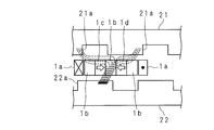
- FIG. 7 shows a state where the mover 1 has advanced a distance corresponding to an electrical angle of 180 degrees from the state of FIG.
- the direction of the current flowing through the coil 1a is reversed.
- the flow of magnetic flux from the upper side to the lower side indicated by the dotted line on the paper surface of FIG. 5 is reversed.
- the tooth portion 21a is excited to the S pole, and the tooth portion 22a is equivalent to being excited to the N pole. Since the excitation of the armature yoke 1b by the permanent magnets 1c and 1d does not change, the tooth portions 21a and 22a that are attracted / repelled are opposite to those in FIG. A suction force is generated in the direction of the arrow shown in FIG.
- the end effect means that in a linear motor, the influence of magnetic attraction and repulsive force generated at both ends of the mover affects the thrust characteristics (cogging characteristics, detent characteristics) of the motor.
- measures such as making the shape of the tooth portions at both ends different from other shapes have been taken.
- the end effect occurs because the magnetic flux loop flows in the same direction as the moving direction (see FIG. 2 of Patent Document 1).
- the loop magnetic flux loop
- the loop magnetic flux loop
- the permanent magnets 1c and 1d are used only for the mover 1, the amount of permanent magnets to be used is increased even when the total length of the linear motor is increased. Therefore, the cost can be reduced. In addition, the influence of the end effect can be reduced.
- the mover 1 has a minimum configuration of two armature yokes 1b and two permanent magnets 1c and 1d. Therefore, it is possible to widen the width in the moving direction of the permanent magnets 1c and 1d included in the mover 1, and to increase the width in the moving direction of the mover 1 of the tooth portions 21a and 22a.
- the armature yoke 1b and the permanent magnets 1c and 1d have a rectangular parallelepiped shape, the invention is not limited thereto.
- any magnetic flux circuit may be used as long as the magnetic flux generated by the excitation of the coil 1a constitutes a magnetic loop circuit in cooperation with the stator 2.
- the armature yoke 1b and the permanent magnets 1c and 1d may be regular hexahedrons.
- FIG. 8 is a plan view showing the mover 1 of the linear motor according to the second embodiment. Since the stator 2 is the same as that of the first embodiment, the description thereof is omitted.
- the width in the moving direction of the armature yoke 10b located in the center and the armature yoke 1b located on the left and right are different.
- the width d2 of the armature yoke 10b is twice the width d1 of the armature yoke 1b. This is to make it difficult for magnetic saturation to occur when the magnetic flux flowing through the armature yokes 1b and 10b increases as the coil current increases.
- the armature yoke 1b located on the left and right exchanges the magnetic flux from one permanent magnet 1c or 1d with the teeth 21a or 22a, whereas the armature yoke 10b located on the center consists of two permanent magnets 1c and 1d. Is exchanged with the tooth portion 21a or 22a. Therefore, it is preferable that the width d2 of the armature yoke 10b located at the center is twice the width d1 of the armature yoke 1b located on the left and right.
- FIG. 9A and 9B are explanatory views of magnetic saturation of the armature yokes 1b and 10b of the mover 1.
- FIG. 9A shows the case of the mover 1 according to the present embodiment.
- FIG. 9B shows the case of the mover 1 according to the first embodiment.
- a dotted line from the tooth portion 21a through the armature yoke 1b, the permanent magnet 1c or 1d to the tooth portion 22a through the armature yoke 1b or 10b indicates the flow of magnetic flux.
- the armature yoke sandwiched between the two permanent magnets 1c and 1d that is, the armature yoke 10b located in the center is wider in the moving direction (length) than the armature yoke 1b in the first embodiment. ) Is getting wider. Therefore, the density of the magnetic flux flowing into the tooth portion 22a is difficult to increase, and magnetic saturation is difficult to occur. In this way, even when the current of the coil 1a is increased, the armature yoke 10b is less likely to cause magnetic saturation, so that the thrust linearity when the current of the linear motor increases is improved.
- the flow of magnetic flux shown in FIG. 9 is shown as an example.
- the width d2 is not limited to twice the width d1.
- the width d2 is twice or more, the armature yoke 10b is not easily saturated. However, even when no magnetic saturation occurs in the armature yoke 10b, the armature yoke 1b at both ends saturates, so the width d2 is preferably twice the width d1. When the width d2 is twice or less, the armature yoke 10b is less likely to cause magnetic saturation than when the width d2 is equal to the width d1, but before the armature yokes 1b at both ends cause magnetic saturation, the armature Magnetic saturation occurs in the yoke 10b. Since the dimension in the moving direction of the mover 1 is determined by the widths d1 and d2, how to set the widths d1 and d2 may be determined in consideration of the above points.
- FIG. 10 is a graph showing the relationship between the current flowing through the coil 1a and the obtained thrust for each of the linear motors according to the first and second embodiments.
- the horizontal axis is current and the unit is ampere (A).
- the vertical axis is thrust, and the unit is Newton (N).
- the linear motor according to the present embodiment (Embodiment 2) is superior to the linear motor according to Embodiment 1 in terms of thrust linearity.
- the linear motor according to the second embodiment has the following effects in addition to the effects achieved by the linear motor according to the first embodiment. Since the width d2 of the armature yoke 10b located in the center is twice the width d1 of the armature yoke 1b located on the left and right, the armature yoke 1b, It is possible to relax the magnetic saturation of 10b and obtain a large thrust. That is, it is possible to obtain a linear motor that optimizes two matters that are in a trade-off relationship between downsizing the mover 1 and increasing thrust. Thereby, there is an effect that the linearity at the time of current increase is more excellent.
- Embodiment 3 In the first embodiment and the second embodiment, the single-phase linear motor (unit for single phase) has been described. However, it is not limited to this.
- the pitch between the three movers is set to n times (an integer multiple of two-thirds) of 2/3 of the stator tooth pitch. It ’s fine.
- an integer n may be set in consideration of the length of each movable element in the longitudinal direction.
- FIG. 11 is a plan view showing a configuration example of the mover 1 of the linear motor according to the third embodiment.
- FIG. 12 is a cross-sectional view showing a cross section taken along a cross-sectional line XII-XII in FIG. 11 and a cross section of the stator 2.
- the linear motor according to the present embodiment is a three-phase motor.
- the mover 1 is configured by arranging three single-phase units 1U, 1V, and 1W similar to the mover 1 in the second embodiment along the moving direction.
- the single phase unit corresponding to the U phase is 1 U
- the single phase unit corresponding to the V phase is 1 V
- the single phase unit corresponding to the W phase is 1 W.
- the three single-phase units 1U, 1V, and 1W all have the same configuration. In each configuration, the same components as those shown in FIG. 8 are denoted by the same reference numerals as those in FIG.
- each single-phase unit 1U, 1V, 1W includes an auxiliary plate 31 and an output unit 32, respectively.
- the auxiliary plate 31 has a rectangular plate shape.
- the auxiliary plate 31 is made of non-magnetic and non-conductive material such as engineering plastic (polyamide, polycarbonate, etc.) or non-magnetic ceramic.
- engineering plastic polyamide, polycarbonate, etc.
- non-magnetic ceramic such as polyamide, polycarbonate, etc.
- the auxiliary plate 31 is in a vertical posture and is disposed between a side surface (side surface parallel to the moving direction) of the armature yokes 1b, 10b, permanent magnets 1c, 1d close to the side plate portion 23 in the short direction and the coil 1a. .
- the auxiliary plate 31 is in close contact with the lateral sides of the armature yokes 1b and 10b and the permanent magnets 1c and 1d.
- the output portion 32 (non-magnetic plate) has a U-shaped longitudinal section and includes a first protruding plate portion 32a, a base portion 32b, and a second protruding plate portion 32c.
- the output unit 32 is made of a nonmagnetic material such as aluminum or nonmagnetic stainless steel. By using a non-magnetic material, a short circuit of magnetic flux generated in the mover 1 can be prevented.
- Each of the first protruding plate portion 32a and the second protruding plate portion 32c has a rectangular plate shape.
- the first projecting plate portion 32a and the second projecting plate portion 32c project substantially vertically upward from a base portion 32b having a rectangular plate shape.
- the first protruding plate portion 32a and the second protruding plate portion 32c are opposed to each other with the winding of the coil 1a interposed therebetween.
- the first projecting plate portion 32a is disposed between the lateral side surfaces (side surfaces parallel to the moving direction) of the armature yokes 1b and 10b, the permanent magnets 1c and 1d, and the windings of the coil 1a.
- the length of the base portion 32b in the longitudinal direction is substantially the same as the value obtained by adding the lengths of the armature yokes 1b and 10b and the permanent magnets 1c and 1d in the short direction.
- the first projecting plate portion 32a is in close contact with the surface facing the side surface with which the auxiliary plate 31 is in close contact among the side surfaces in the short direction of the armature yokes 1b and 10b and the permanent magnets 1c and 1d.
- the auxiliary plate 31 and the first protruding plate portion 32a prevent the armature yokes 1b and 10b and the permanent magnets 1c and 1d from being displaced from each other.
- the mover 1 includes a connecting plate 4 (connecting portion) that is long in the moving direction.
- Each single-phase unit is connected by fixing the connecting plate 4 and the second protruding plate portion 32c included in each single-phase unit with a screw or the like.
- the mover 1 is supported so as to be movable from the first projecting plate portion 32a, which is a non-magnetic material, via the base portion 32b and the second projecting plate portion 32c. Since the first protruding plate portion 32a is located between the armature yokes 1b and 10b and the coil 1a, for example, when the mover 1 is supported, the mover 1 can be reduced in size as compared with the case where the side surface of the coil 1a is supported. .
- the current flowing through the coils 1a of the three single-phase units is a three-phase alternating current (a symmetric three-phase alternating current).
- the white arrows shown in FIG. 13 indicate the magnetization directions of the permanent magnets 1c and 1d as in FIG.
- the stator 2 is the same as that in the first and second embodiments, and thus the description thereof is omitted.
- FIG. 13 is a diagram for explaining the operation of the linear motor according to the third embodiment.
- FIG. 13 is a side view of the linear motor.
- the coil wire of the coil 1a passing in the left-right direction in FIG. 13 is not shown for explanation.
- the mover phase pitch P2 is set to a value equal to 2/3 ⁇ 2 times the pitch P1 of the tooth portion 21a (22a) (2/3 times P1).
- the state shown in FIG. 13 shows a state in which current flows through the U-phase and W-phase coils 1a and no current flows through the V-phase coil 1a.
- the principle by which the W-phase mover 1W generates thrust is the same as in the case of FIG.
- the principle by which the U-phase mover 1U generates thrust is the same as in the case of FIG.
- the mover 1 continues to move.
- FIG. 14 is a graph showing the thrust of the linear motor according to the third embodiment.
- the horizontal axis is the moving distance of the mover 1, and the unit is millimeter (mm).
- the vertical axis represents thrust, and the unit is Newton (N).
- the combined thrust of the three phases is about 2.5 times the single-phase peak thrust.
- the thrust waveform per single phase is made substantially sinusoidal, the thrust waveform after the three-phase synthesis is smoothed, and thrust pulsation is removed.
- the three-phase combined thrust is about 1.4 times the single-phase peak thrust.
- the linear motor of the present embodiment has a length L1 along the moving direction of the mover 1 of the tooth portion 21a (tooth portion 22a) shown in FIGS.
- the following effects are achieved. Since the auxiliary plate 31 formed of a non-conductor is provided between the armature yokes 1b and 10b and the coil 1a, the flow path of eddy currents flowing through the armature yokes 1b and 10b is partially blocked, and eddy current loss Can be reduced. Since the movable element 1 is formed by connecting three single-phase units, it is possible to obtain a larger thrust than in the case of one single-phase unit. By providing the second protruding plate portion 32c, the thrust of the linear motor can be easily transmitted to the outside.
- the single-phase units are connected to each other by fixing the second projecting plate portion 32c and the connection plate 4 included in each single-phase unit 1U, 1V, 1W with screws or the like.
- the present invention is not limited thereto, and a configuration without the connecting plate 4 may be used. That is, if the second projecting plate portion 32c of each single-phase unit is integrally formed, the connecting plate 4 becomes unnecessary.
- the output portion 32 has a U-shaped cross section, but may have a configuration with the base portion 32b facing up, that is, an inverted U-shaped cross section.
- the configuration in which the auxiliary plate 31 is provided between the side surfaces of the armature yokes 1b and 10b, the permanent magnets 1c and 1d in the short direction and the coil 1a is also applicable to the first and second embodiments.
- Embodiment 4 When the permanent magnets 1c and 1d and the armature yoke 1b are arranged on the mover 1, the relative permeability periodically changes in the moving direction, so that higher-order detent force harmonic components become conspicuous. In general, in the case of phase-independent driving, the fundamental wave and the second-order and fourth-order harmonics are canceled during the three-phase synthesis, but the third-order, sixth-order, ninth-order, and 12th-order harmonics strengthen each other It will be.
- FIG. 15 is a plan view showing a configuration example of the mover 1 of the linear motor according to the fourth embodiment.
- the surfaces of the permanent magnets 1c and 1d and the armature yoke 1b on the moving direction side are inclined in a direction intersecting the moving direction and the opposing direction of the upper plate portion and the lower plate portion.
- This is a so-called skew arrangement.
- the skew arrangement is to arrange the long sides of the permanent magnets 1c and 1d and the armature yoke 1b with an inclination (angle) with respect to the direction orthogonal to the moving direction. That is, the longitudinal direction both ends of the permanent magnets 1c and 1d and the armature yoke 1b are different from each other in the movement direction. Thereby, it is possible to reduce the harmonic components of the 12th order or higher.
- the skew angle (skew angle) is about 0 to 6 degrees. Since the stator 2 is the same as that of the first embodiment, the description thereof is omitted
- the linear motor according to the fourth embodiment has the effect of reducing the harmonic component of the detent force in addition to the effect exhibited by the linear motor according to the first embodiment.
- the armature yoke 1b and the permanent magnets 1c and 1d are arranged in a rectangular parallelepiped shape.
- the armature yoke 1b and the permanent magnets 1c and 1d facing the inner peripheral surface of the coil 1a are respectively connected to the two surfaces.
- the coil 1a may be configured to be parallel to the inner peripheral surface. That is, one section of the armature yoke 1b permanent magnets 1c and 1d may be a parallelogram.
- FIG. 16 is a cross-sectional view showing the configuration of the stator 2 of the linear motor according to the fifth embodiment.
- FIG. 16 is a cross-sectional view of the linear motor stator 2 cut along the moving direction of the mover 1.
- the short side any two sides
- the tooth portion 21a of the upper plate portion 21 and the tooth portion 22a of the lower plate portion 22 are so-called skewed. This will be described using the third tooth portion 21a from the left in FIG.
- the cross section of the tooth portion 21a is rectangular.
- a rectangle indicated by a dotted line indicates a case where the tooth portion 21a is not skewed.
- the moving direction of the mover 1 is the left-right direction.
- the short side of the tooth portion 21a indicated by the dotted line is parallel to the moving direction of the mover 1.
- the short cross-sections E1 and E2 are inclined with respect to the moving direction of the mover 1.
- the tooth part 22a has an end face at the tip in the protruding direction.
- a rectangle indicated by a dotted line indicates a case where the tooth portion 22a is not skewed.
- the short side of the end face is parallel to the moving direction of the mover 1 and is not inclined.
- the short sides E3 and E4 of the end face are inclined with respect to the moving direction of the mover 1. Since the cross section of the tooth portion 22a has the same shape as the end face, the short side of the cross section is similarly inclined with respect to the moving direction of the mover 1.
- the mover 1 is the same as that of any one of the first to fourth embodiments described above, and a description thereof will be omitted.
- the detents can be obtained without skewing the armature yoke 1b (10b) and the permanent magnets 1c and 1d of the mover 1 by arranging the tooth portions 21a and the tooth portions 22a of the stator 2 in a skewed manner. It becomes possible to reduce harmonic components of the 12th and higher order of the force.
- mover 1, the permanent magnet 1c, The angle formed by 1d is related.
- the teeth 21a and 22a of the stator 2, the armature yoke 1b of the mover 1, and the permanent magnets 1c and 1d may be skewed so that the angle formed becomes an appropriate value.
- FIG. 17 is a cross-sectional view showing the configuration of the stator 2 of the linear motor according to the sixth embodiment.
- FIG. 3 is a cross-sectional view of the linear motor stator 2 cut along the moving direction of the mover 1.
- the tooth portion 21a of the upper plate portion 21 and the tooth portion 22a of the lower plate portion 22 are arranged in a skew manner. That is, the tooth part 21 a and the tooth part 22 a of the stator 2 are arranged so as to be inclined with respect to the moving direction of the mover 1.
- the mover 1 is the same as that of any one of the first to fourth embodiments described above, and a description thereof will be omitted.
- the tooth portion 21a provided in one plate-like portion 21 and the tooth portion 22a provided in the other plate-like portion 22 are reversed in the direction of inclination of the short side.
- the cross-section short sides E1 and E2 of the tooth portion 21a, the end face short sides of the tooth portion 22a, and E3 and E4 are inclined with respect to the moving direction of the mover 1. This is the same as in the fifth embodiment described above.
- the directions of inclination between the tooth portion 21a and the tooth portion 22a are reversed. That is, the inclination directions of the short cross sections E1 and E2 of the tooth portion 21a and the short cross sections E3 and E4 of the tooth portion 22a are opposite to each other.
- the thrust generated in the linear motor is generated in a direction inclined by a skew angle from the moving direction of the mover 1, and therefore the entire mover 1 may be tilted.
- the thrust component in the direction (lateral direction) perpendicular to the moving direction of the mover 1 generated by the tooth portion 21a and the tooth portion 22a is reversed. Therefore, the thrust components in the lateral direction cancel each other and can be prevented from being twisted.
- the sixth embodiment has the following effects in addition to the effects of the linear motors according to the first to fourth embodiments.
- the armature yoke 1b (10b) and the permanent magnets 1c and 1d of the mover 1 are not skewed, and the detent force is higher than the 12th order. Wave components can be reduced.
- the direction in which the tooth portion 21a and the tooth portion 22a are inclined is reversed, thereby providing an effect of preventing twisting.
- the mover 1 in the fourth embodiment similarly to the fifth embodiment, it is possible to use the mover 1 in the fourth embodiment, and the armature yoke 1b, the permanent magnets 1c and 1d of the mover 1, and the stator.
- the skew angles of the two tooth portions 21a and 22a may be determined as appropriate.
Abstract
Description
また、3相リニアモータでは可動子の位置により変動する3相の合成推力の変動幅を低減させるため、単相あたりの推力波形をほぼ正弦波とする必要がある。又推力を確保する必要がある。その手段の一つとして、各相に複数の磁極を設けて狭ピッチ化を図るのが一般的であり、そのことが可動子構造の簡素化や固定子及び可動子の小型化、軽量化を阻んでいた。
また挟ピッチ化した場合には駆動周波数の高周波化を招き、リニアモータ自体の鉄損が増大するという問題があった。 In a moving coil type linear motor, since magnets are arranged on the stator, the amount of magnets to be used increases as the total length of the linear motor increases (the moving distance of the mover increases). In recent years, with the increase in the price of rare earths, an increase in the amount of magnets used has caused an increase in cost.
Further, in a three-phase linear motor, the thrust waveform per single phase needs to be substantially a sine wave in order to reduce the fluctuation range of the three-phase combined thrust that varies depending on the position of the mover. It is also necessary to ensure thrust. As one of the means, it is common to reduce the pitch by providing a plurality of magnetic poles in each phase, which simplifies the mover structure and reduces the size and weight of the stator and mover. I was blocking.
In addition, when the pitch is reduced, the drive frequency is increased, and the iron loss of the linear motor itself is increased.
ここで本明細書及び請求項で使用する電機子ヨークとヨークは同じ意味として使用する。 In the present invention, since the stator has a minimum configuration including two magnets and three yokes, the dimension of the mover in the moving direction can be further reduced. In addition, since no magnet is used for the stator, there is an effect that the amount of magnet used does not increase even when the linear motor has a long overall length.
Here, the armature yoke and the yoke used in the present specification and claims are used interchangeably.
図1は実施の形態1に係るリニアモータの概略構成の一例を示す部分破断斜視図である。図2は実施の形態1に係るリニアモータの可動子1の構成例を示す平面図である。図3は実施の形態1に係るリニアモータの概略構成を示す断面図である。図4は実施の形態1に係るリニアモータの概略構成を示す側面図である。
FIG. 1 is a partially broken perspective view showing an example of a schematic configuration of the linear motor according to the first embodiment. FIG. 2 is a plan view showing a configuration example of the
また略コの字に形成した磁性鋼板の歯部となる部位を残し歯部となる部位の両側に溝を掘り込み加工により形成し、歯部21a、歯部22aとしてもよい。このようにすると、歯部を溶接等で接合又はねじ止め等により固定する場合に比べて、固定子2のコストダウンが可能となる。さらにまた、板状部材で歯部21a、歯部22aとなる部分を残しスリットを形成しても良い。または歯部21a、歯部22aとなる部分をくし歯状に形成しても良い。なお、図3に示す向きで設置されることが固定子2の必須の要件ではない。設置可能な如何なる向きで使用することも可能である。上板部21が下側や左右側となるように設置しても良い。 As shown in FIG. 3, the
Alternatively, the
また永久磁石1c及び1dが電機子コア1bよりも長い場合には、推力に寄与する磁束の上板部21又は下板部22の板面の法線方向の成分を確保しにくくなるため、推力ロスが発生する。後述する様に、本発明の推力は電機子ヨーク1bと歯部21aとの間、及び電機子ヨーク1bと歯部22aとの間に流れる磁束量によるため、永久磁石1c及び1dが突出している場合には、歯部21aと電機子ヨーク1bとの距離、及び歯部22aと電機子ヨーク1bとの距離が遠くなり、推力が低減する。
なお、ここで略同じとは構造部を設計する上での寸法設定では同じということを意味している。そして、加工設備による加工誤差を含むため、設計上の寸法設定に公差を含めた上で略同じと表記している。 The length of the
In addition, when the
Here, “substantially the same” means that the dimensions are the same in designing the structure. In addition, since it includes a processing error due to processing equipment, it is described as substantially the same after including a tolerance in design dimension setting.
言い換えると1相あたりの歯部のピッチを相対的に大きくすることができる。 When the number of
In other words, the tooth pitch per phase can be relatively increased.
つまり電機子ヨーク1bが4個以上の場合には次のような問題がある。L1+L2>L3にすると、隣り合う電機子ヨーク1bの間隔が小さくなる。永久磁石1c、1dを介して隣り合う電機子ヨーク1bの永久磁石1c、1dによる界磁方向はそれぞれ異なるので、一つの歯部21a(22a)との間で吸引と反発とが短い距離で行われることとなり、可動子1と固定子2の間で発生する推力を低下させる。 On the other hand, when the number of
That is, when there are four or
一方、固定子2の歯部21aはN極、歯部22aはS極に励磁されている。歯部21a、22aに発生した磁極と、永久磁石1c、1dにより励磁された電機子ヨーク1bの磁極が吸引又は反発することにより、可動子1には図6の紙面左向きの推力が発生する。 Next, generation of magnetic poles and generation of thrust by the
On the other hand, the
また、可動子1は電機子ヨーク1bを3個、永久磁石1c、1dを各1個の計2個という最小の構成としている。そのため、可動子1の備える永久磁石1c、1dの移動方向の幅を広くすること、及び歯部21a、22aの可動子1の移動方向の幅を大きくすることも可能となる。それによって、電機子ヨーク、永久磁石の数が多い同一サイズの固定子よりも大きな推力を得ることが可能となる。
なお、実施の形態1では可動子1がすべて上板部21と下板部22とに挟まれている形態を示したが、本発明においては可動子1のうち永久磁石1c、1dと電機子ヨーク1bが固定子2に挟まれていればよく、コイル1aの一部が固定子2から突出していてもよい。
また、電機子ヨーク1b、永久磁石1c、1dは直方体状としたが、それに限られない。コイル1aの励磁により発生した磁束が固定子2と協同した磁気ループ回路を構成するものであれば良い。例えば、電機子ヨーク1b、永久磁石1c、1dが正六面体であっても良い。 As described above, in the linear motor according to the first embodiment, since the
The
In the first embodiment, all the
Moreover, although the
図8は実施の形態2に係るリニアモータの可動子1を示す平面図である。固定子2については、実施の形態1と同様であるので、説明を省略する。
FIG. 8 is a plan view showing the
なお、幅d2は幅d1の2倍に限られない。幅d2が2倍以上であれば、電機子ヨーク10bが飽和しにくくなる。しかしながら、電機子ヨーク10bで磁気飽和が起きない場合でも、両端の電機子ヨーク1bで飽和するので、幅d2は幅d1の2倍が好適である。幅d2が2倍以下である場合は、幅d2と幅d1が等しい場合よりも電機子ヨーク10bで磁気飽和を起こしにくくなるが、両端の電機子ヨーク1bが磁気飽和を起こす前に、電機子ヨーク10bで磁気飽和が起こることとなる。幅d1、d2により可動子1の移動方向の寸法が決まるので、幅d1、d2をどのように設定するかは、上述した点を考慮して決定すれば良い。 9A and 9B are explanatory views of magnetic saturation of the armature yokes 1b and 10b of the
The width d2 is not limited to twice the width d1. If the width d2 is twice or more, the
実施の形態1及び実施の形態2においては、単相のリニアモータ(単相分のユニット)について説明した。しかしこれに限られるものではない。例えば3相駆動のリニアモータを構成する場合には、その3個の各可動子間のピッチを、固定子歯部のピッチの2/3のn倍(3分の2の整数倍)にすれば良い。またこの場合、各可動子の長手方向の長さを考慮して整数nを設定すれば良い。
In the first embodiment and the second embodiment, the single-phase linear motor (unit for single phase) has been described. However, it is not limited to this. For example, in the case of configuring a three-phase drive linear motor, the pitch between the three movers is set to n times (an integer multiple of two-thirds) of 2/3 of the stator tooth pitch. It ’s fine. In this case, an integer n may be set in consideration of the length of each movable element in the longitudinal direction.
非磁性体とすることで可動子1内に発生した磁束の短絡を防止できる。
第1突出板部32a、第2突出板部32cはそれぞれ矩形板状をなしている。第1突出板部32a、第2突出板部32cは矩形板状をなす基部32bから略垂直上に突出している。第1突出板部32a及び第2突出板部32cはコイル1aの巻線を間にして対向している。第1突出板部32aは電機子ヨーク1b、10b、永久磁石1c、1dの短手方向の側面(移動方向に平行な側面)とコイル1aの巻線との間に配されている。基部32bの長手方向の長さは、電機子ヨーク1b、10b、永久磁石1c、1dの短手方向の長さを加算した値と略同一である。第1突出板部32aは、電機子ヨーク1b、10b、永久磁石1c、1dの短手方向の側面のうち、補助板31が密着している側面に対向する面と密着している。補助板31と第1突出板部32aとにより、電機子ヨーク1b、10b、永久磁石1c、1dが相互にズレないようにしている。可動子1は移動方向に長い連結板4(連結部)を含んでいる。各単相ユニットは連結板4と各単相ユニットが備える第2突出板部32cとがネジ等で固定されることにより連結される。
可動子1の支持は非磁性体である第1突出板部32aから、基部32b、第2突出板部32cを介して可動可能に行われる。
第1突出板部32aは電機子ヨーク1b、10bとコイル1aとの間にあるため、たとえば可動子1を支持する際にコイル1aの側面を支持する場合に比べて可動子1を小型化できる。 FIG. 11 is a plan view showing a configuration example of the
By using a non-magnetic material, a short circuit of magnetic flux generated in the
Each of the first protruding plate portion 32a and the second protruding
The
Since the first protruding plate portion 32a is located between the armature yokes 1b and 10b and the coil 1a, for example, when the
横軸は可動子1の移動距離であり、単位はミリメートル(mm)である。
縦軸は推力であり、単位はニュートン(N)である。図14に示すように3相の合成推力が単相ピーク推力の2.5倍程度となっている。一般的には単相あたりの推力波形を略正弦波状にして、3相合成後の推力波形を平滑化し、推力脈動を除去する。しかし、この場合に3相合成推力は単相ピーク推力の1.4倍程度に留まる。これに対して、本実施の形態のリニアモータは図3および図4に示す歯部21a(歯部22a)の可動子1の移動方向に沿う長さL1と、2つの歯部21a(歯部22a)の間隔L2との比を6対4にしているので、固定子2に対して可動子1の相対位置が変化したときの推力波形の分布が、正弦波状から台形波状に変化する。その結果、推力脈動は大きくなるものの、3相合成推力を大幅に高められている。つまり、リニアモータの小型化と高推力化の両立を可能にしている。
なお、合成推力は移動距離により周期的に変動しているが、PID(Proportional Integral Derivative)制御により適切なフィードバックを掛けることにより、変動幅が小さくなるように電流を制御すれば良い。 FIG. 14 is a graph showing the thrust of the linear motor according to the third embodiment.
The horizontal axis is the moving distance of the
The vertical axis represents thrust, and the unit is Newton (N). As shown in FIG. 14, the combined thrust of the three phases is about 2.5 times the single-phase peak thrust. Generally, the thrust waveform per single phase is made substantially sinusoidal, the thrust waveform after the three-phase synthesis is smoothed, and thrust pulsation is removed. However, in this case, the three-phase combined thrust is about 1.4 times the single-phase peak thrust. In contrast, the linear motor of the present embodiment has a length L1 along the moving direction of the
The composite thrust periodically varies depending on the moving distance, but the current may be controlled so that the variation range is reduced by applying appropriate feedback by PID (Proportional Integral Derivative) control.
図12に示すように出力部32は断面U字状としたが、基部32bを上にした構成、すなわち、断面逆U字状としても良い。
電機子ヨーク1b、10b、永久磁石1c、1dの短手方向の側面とコイル1aとの間に補助板31を設ける構成は、上述の実施の形態1及び2においても適用可能である。 In the present embodiment, the single-phase units are connected to each other by fixing the second projecting
As shown in FIG. 12, the
The configuration in which the
可動子1に永久磁石1c、1dと電機子ヨーク1bとが配列されている場合、移動方向で比透磁率が周期的に変化するため、高次のディテント力高調波成分が顕著になる。一般に相独立型の駆動では、3相合成時に基本波及び2次、4次の高調波は打ち消されるが、3次、6次、9次、12次などの3の倍数の高調波は強め合うこととなる。
When the
また、電機子ヨーク1b、永久磁石1c、1dは、直方体状のものを配置しているが、コイル1aの内周面と対向する電機子ヨーク1b、永久磁石1c、1dのそれぞれの2面を、コイル1aの内周面と平行となるよう構成しても良い。すなわち、電機子ヨーク1b永久磁石1c、1dの一つの断面が平行四辺形となるようにしても良い。 As described above, the linear motor according to the fourth embodiment has the effect of reducing the harmonic component of the detent force in addition to the effect exhibited by the linear motor according to the first embodiment.
Further, the
図16は実施の形態5に係るリニアモータの固定子2の構成を示す断面図である。図16はリニアモータの固定子2を、可動子1の移動方向に沿って切断した横断面図である。歯部の21a、22aの上板部21又は下板部22に平行な断面の向かい合う二組の2辺のうち短辺(いずれかの2辺)は、可動子1の移動方向に対し傾斜している。上板部21が有する歯部21a及び下板部22が有する歯部22aを所謂スキュー配置している。図16の左から3番目の歯部21aを用いて説明する。歯部21aの断面は長方形である。点線で示す長方形は歯部21aをスキュー配置していない場合を示している。図16において、可動子1の移動方向は左右の方向である。スキュー配置していない場合、点線で示す歯部21aの断面短辺は可動子1の移動方向に対して、平行である。スキュー配置した場合、断面短辺E1とE2は可動子1の移動方向に対して傾斜していることとなる。図16では歯部22aは突出方向先端の端面が現れている。図16の左から二番目の歯部22aにおいて、点線で示す長方形は歯部22aがスキュー配置していない場合を示している。端面の短辺は可動子1の移動方向と平行であり、傾斜していない。スキュー配置した場合、端面の短辺E3、E4は可動子1の移動方向に対して傾斜している。歯部22aの断面は端面と同一形状であるから、断面短辺も同様に可動子1の移動方向に対して傾斜することとなる。
FIG. 16 is a cross-sectional view showing the configuration of the
図17は実施の形態6に係るリニアモータの固定子2の構成を示す断面図である。リニアモータの固定子2を可動子1の移動方向に沿って切断した横断面図である。上板部21が有する歯部21a及び下板部22の有する歯部22aをスキュー配置している。すなわち、固定子2の歯部21a及び歯部22aは、可動子1の移動方向に対して傾斜するように配置してある。可動子1については、上述の実施の形態1から実施の形態4のいずれかと同様であるので、説明を省略する。
FIG. 17 is a cross-sectional view showing the configuration of the
今回開示された実施の形態はすべての点で例示であって、制限的なものでは無いと考えられるべきである。本発明の範囲は、上記した意味では無く、特許請求の範囲によって示され、特許請求の範囲と均等の意味及び範囲内でのすべての変更が含まれることが意図される。 The technical features (components) described in each embodiment can be combined with each other, and new technical features can be formed by combining them.
The embodiments disclosed herein are illustrative in all respects and should not be considered as restrictive. The scope of the present invention is defined not by the above-mentioned meaning but by the scope of the claims, and is intended to include all modifications within the meaning and scope equivalent to the scope of the claims.
1a コイル
1b、10b 電機子ヨーク(ヨーク)
1c、1d 永久磁石(磁石)
2 固定子
21 上板部
21a 歯部
22 下板部
22a 歯部
23 側板部
31 補助板
32 出力部(非磁性体板)
32a 第1突出板部
32b 基部
32c 第2突出板部
4 連結板(連結部)
DESCRIPTION OF
1c, 1d Permanent magnet (magnet)
2
32a 1st
Claims (10)
- 固定子、及びコイルを有する可動子を備えたリニアモータにおいて、
前記固定子は前記可動子の移動方向に長い2つの板状部を有し、2つの板状部は可動子の移動域を間にして、磁気的に結合するように対向して設けてあり、
前記2つの板状部の互いに対向する面それぞれには、複数の歯部が、一方の板状部の歯部と他方の板状部の歯部とで千鳥状となるように前記移動方向に並設してあり、
前記可動子は前記コイル内部に、前記移動方向に沿って2つの磁石及び3つのヨークが交互に配列してあり、
前記2つの磁石は前記移動方向に沿って磁化してあり、磁化方向は互いに対向すること
を特徴とするリニアモータ。 In a linear motor including a stator and a mover having a coil,
The stator has two plate-like portions that are long in the moving direction of the mover, and the two plate-like portions are provided facing each other so as to be magnetically coupled with the moving region of the mover in between. ,
In each of the surfaces of the two plate-like parts facing each other, a plurality of tooth parts are arranged in the moving direction so that the tooth parts of one plate-like part and the tooth parts of the other plate-like part are staggered. Side by side,
In the mover, two magnets and three yokes are alternately arranged in the coil along the moving direction.
The linear motor is characterized in that the two magnets are magnetized along the moving direction, and the magnetizing directions oppose each other. - 前記2つの磁石に挟まれているヨークが他の2つのヨークより前記移動方向に長いこと
を特徴とする請求項1に記載のリニアモータ。 The linear motor according to claim 1, wherein a yoke sandwiched between the two magnets is longer in the moving direction than the other two yokes. - 前記2つの磁石に挟まれているヨークの前記移動方向の長さは、他の2つのヨークの2倍の長さであること
を特徴とする請求項2に記載のリニアモータ。 The linear motor according to claim 2, wherein a length of the yoke sandwiched between the two magnets in the moving direction is twice that of the other two yokes. - 前記歯部の並設方向の幅が、歯部の並設間隔よりも長いこと
を特徴とする請求項1から請求項3のいずれか一項に記載のリニアモータ。 The linear motor according to any one of claims 1 to 3, wherein a width of the tooth portions in the juxtaposed direction is longer than an interval between the tooth portions. - 前記2つの磁石及び3つのヨークが直方体状をなし、各磁石及び各ヨークの前記移動方向側の面は、前記移動方向及び前記板状部の対向方向と直交する方向に対して傾斜していること
を特徴とする請求項1から請求項4のいずれか一項に記載のリニアモータ。 The two magnets and the three yokes have a rectangular parallelepiped shape, and the surfaces of the magnets and the yokes on the moving direction side are inclined with respect to a direction orthogonal to the moving direction and the opposing direction of the plate-like portion. The linear motor according to any one of claims 1 to 4, wherein the linear motor is characterized. - 前記歯部が直方体状をなし、
前記歯部の前記板状部に平行な断面の向かい合ういずれかの2辺は前記移動方向に対し傾斜していること
を特徴とする請求項1から請求項5のいずれか一項に記載のリニアモータ。 The tooth portion has a rectangular parallelepiped shape,
6. The linear according to claim 1, wherein any two sides of a cross section of the tooth portion that are parallel to the plate-like portion are inclined with respect to the moving direction. motor. - 前記2つの板状部が有する歯部は、前記断面の前記2辺の傾斜方向が互いに逆であること
を特徴とする請求項6に記載のリニアモータ。 7. The linear motor according to claim 6, wherein the tooth portions of the two plate-like portions have inclination directions of the two sides of the cross section opposite to each other. - 前記ヨーク及び磁石の前記移動方向に平行な側面と前記コイルとの間に設けられた板状の非磁性体板と該非磁性体板と前記ヨーク及び磁石を介して対向しかつ前記コイルとの間に設けられた板状の非磁性非導電性材からなる補助板を備えること
を特徴とする請求項1から請求項7のいずれか一項に記載のリニアモータ。 A plate-like nonmagnetic plate provided between a side surface of the yoke and the magnet parallel to the moving direction and the coil, and the nonmagnetic plate facing the yoke and the magnet and between the coil The linear motor according to any one of claims 1 to 7, further comprising an auxiliary plate made of a plate-like nonmagnetic nonconductive material provided on the plate. - 前記非磁性体板に連結され、前記移動方向に配列される3つの可動子を連結する連結部をさらに備えること
を特徴とする請求項8に記載のリニアモータ。 The linear motor according to claim 8, further comprising a connecting portion that is connected to the nonmagnetic plate and connects three movers arranged in the moving direction. - 前記非磁性体板は、
前記コイルの巻線を間にして対向する板状の第1突出板部及び第2突出板部と、
前記第1突出板部及び前記第2突出板部を結ぶ基部を有すること
を特徴とする請求項9に記載のリニアモータ。 The non-magnetic plate is
A plate-like first projecting plate portion and a second projecting plate portion facing each other with the winding of the coil interposed therebetween;
The linear motor according to claim 9, further comprising a base portion that connects the first protruding plate portion and the second protruding plate portion.
Priority Applications (4)
| Application Number | Priority Date | Filing Date | Title |
|---|---|---|---|
| CN201480017512.7A CN105075081B (en) | 2013-03-22 | 2014-03-17 | Linear electric motors |
| EP14769204.0A EP2978113A4 (en) | 2013-03-22 | 2014-03-17 | Linear motor |
| US14/777,731 US10044251B2 (en) | 2013-03-22 | 2014-03-17 | Linear motor |
| JP2015506768A JP6128206B2 (en) | 2013-03-22 | 2014-03-17 | Linear motor |
Applications Claiming Priority (2)
| Application Number | Priority Date | Filing Date | Title |
|---|---|---|---|
| JP2013-060515 | 2013-03-22 | ||
| JP2013060515 | 2013-03-22 |
Publications (1)
| Publication Number | Publication Date |
|---|---|
| WO2014148434A1 true WO2014148434A1 (en) | 2014-09-25 |
Family
ID=51580113
Family Applications (1)
| Application Number | Title | Priority Date | Filing Date |
|---|---|---|---|
| PCT/JP2014/057141 WO2014148434A1 (en) | 2013-03-22 | 2014-03-17 | Linear motor |
Country Status (6)
| Country | Link |
|---|---|
| US (1) | US10044251B2 (en) |
| EP (1) | EP2978113A4 (en) |
| JP (1) | JP6128206B2 (en) |
| CN (1) | CN105075081B (en) |
| TW (1) | TWI513150B (en) |
| WO (1) | WO2014148434A1 (en) |
Cited By (1)
| Publication number | Priority date | Publication date | Assignee | Title |
|---|---|---|---|---|
| US11377325B2 (en) * | 2013-12-05 | 2022-07-05 | Otis Elevator Company | Linear propulsion system |
Families Citing this family (5)
| Publication number | Priority date | Publication date | Assignee | Title |
|---|---|---|---|---|
| DE112016001548T5 (en) * | 2015-03-31 | 2018-01-04 | Hitachi Metals, Ltd. | ANCHOR FOR A LINEAR ENGINE, AND LINEAR ENGINE USING THIS ANCHOR |
| EP3547512A1 (en) * | 2018-03-28 | 2019-10-02 | KONE Corporation | Electric linear motor |
| US10491093B2 (en) | 2018-12-17 | 2019-11-26 | Konstantin Hadziristic | Tubular linear induction motor suitable for transportation |
| CN112234798B (en) * | 2020-09-04 | 2023-06-27 | 瑞声新能源发展(常州)有限公司科教城分公司 | Linear motor |
| US20240055967A1 (en) | 2020-12-17 | 2024-02-15 | Swisspod Technologies Sa | Self guided linear induction motor system and method |
Citations (7)
| Publication number | Priority date | Publication date | Assignee | Title |
|---|---|---|---|---|
| JPS62126858A (en) * | 1985-11-27 | 1987-06-09 | Shinko Electric Co Ltd | Skew structure for linear pulse motor |
| JPH0232750A (en) * | 1988-07-20 | 1990-02-02 | Shinko Electric Co Ltd | Pulse motor |
| JPH03139160A (en) | 1989-10-20 | 1991-06-13 | Shinko Electric Co Ltd | Pulse motor |
| JPH0588192U (en) * | 1992-01-10 | 1993-11-26 | 郵政大臣 | Linear motor iron core |
| JPH08502880A (en) * | 1992-11-04 | 1996-03-26 | エコル ノルマル シュペリユール ド カシャン(レジール) | Electromechanical transducer for generating linear motion |
| JPH11313475A (en) * | 1998-04-28 | 1999-11-09 | Yaskawa Electric Corp | Linear motor |
| JP2001045735A (en) * | 1999-08-02 | 2001-02-16 | Yaskawa Electric Corp | Moving body structure of linear motor |
Family Cites Families (22)
| Publication number | Priority date | Publication date | Assignee | Title |
|---|---|---|---|---|
| JPS61161952A (en) * | 1985-01-09 | 1986-07-22 | Yaskawa Electric Mfg Co Ltd | 3-phase linear inductor type motor |
| US4857781A (en) * | 1988-07-13 | 1989-08-15 | Eastman Kodak Company | High-speed non-contact linear motor with magnetic levitation |
| US5010262A (en) | 1988-07-20 | 1991-04-23 | Shinko Electric Company Ltd. | Strong magnetic thrust force type actuator |
| DE68910649T2 (en) | 1988-11-22 | 1994-05-19 | Shinko Electric Co Ltd | Actuator with strong magnetic pushing force. |
| JPH0734646B2 (en) * | 1989-07-15 | 1995-04-12 | 松下電工株式会社 | Linear motor |
| JP4094769B2 (en) * | 1999-05-18 | 2008-06-04 | 日本トムソン株式会社 | Slide device with built-in moving coil type linear motor |
| JP2001145328A (en) * | 1999-11-17 | 2001-05-25 | Nikon Corp | Linear motor, and stage apparatus and aligner therewith |
| JP3945142B2 (en) * | 2000-10-12 | 2007-07-18 | 株式会社日立製作所 | Linear motor and control method thereof |
| JP3945149B2 (en) * | 2000-11-06 | 2007-07-18 | 株式会社日立製作所 | Linear motor and manufacturing method thereof |
| US7362012B2 (en) * | 2001-04-09 | 2008-04-22 | Bei Sensors And Systems Company, Inc. | Ironcore linear brushless DC motor with reduced detent force |
| JP3848596B2 (en) * | 2002-06-11 | 2006-11-22 | ファナック株式会社 | Linear motor |
| JP4537745B2 (en) | 2004-03-30 | 2010-09-08 | 株式会社日立製作所 | Linear motor |
| JP2006136156A (en) | 2004-11-08 | 2006-05-25 | Okuma Corp | Linear motor |
| DE102006005046A1 (en) * | 2006-02-03 | 2007-08-09 | Siemens Ag | Electric machine with uneven pole teeth |
| CN101496264B (en) | 2006-07-26 | 2012-10-10 | 株式会社安川电机 | Cylindrical linear motor , armature, cylindrical linear motor field pole |
| KR100820160B1 (en) * | 2006-07-28 | 2008-04-08 | 한국전기연구원 | Permanent magnet excited transverse flux linear motor with normal-force compensation structure |
| JP5741573B2 (en) | 2010-03-23 | 2015-07-01 | 日立金属株式会社 | Linear motor |
| US10218252B2 (en) * | 2010-06-09 | 2019-02-26 | Hitachi, Ltd. | Linear motor and positioning apparatus |
| JP5015290B2 (en) * | 2010-06-16 | 2012-08-29 | Thk株式会社 | Linear motor |
| TWI500241B (en) | 2012-02-16 | 2015-09-11 | Hitachi Metals Ltd | Linear motor |
| JP6156716B2 (en) * | 2012-08-21 | 2017-07-05 | シンフォニアテクノロジー株式会社 | Transport device |
| JP6098923B2 (en) * | 2012-12-27 | 2017-03-22 | シンフォニアテクノロジー株式会社 | Transport device |
-
2014
- 2014-03-17 EP EP14769204.0A patent/EP2978113A4/en not_active Withdrawn
- 2014-03-17 CN CN201480017512.7A patent/CN105075081B/en not_active Expired - Fee Related
- 2014-03-17 US US14/777,731 patent/US10044251B2/en active Active
- 2014-03-17 JP JP2015506768A patent/JP6128206B2/en active Active
- 2014-03-17 WO PCT/JP2014/057141 patent/WO2014148434A1/en active Application Filing
- 2014-03-19 TW TW103110212A patent/TWI513150B/en not_active IP Right Cessation
Patent Citations (7)
| Publication number | Priority date | Publication date | Assignee | Title |
|---|---|---|---|---|
| JPS62126858A (en) * | 1985-11-27 | 1987-06-09 | Shinko Electric Co Ltd | Skew structure for linear pulse motor |
| JPH0232750A (en) * | 1988-07-20 | 1990-02-02 | Shinko Electric Co Ltd | Pulse motor |
| JPH03139160A (en) | 1989-10-20 | 1991-06-13 | Shinko Electric Co Ltd | Pulse motor |
| JPH0588192U (en) * | 1992-01-10 | 1993-11-26 | 郵政大臣 | Linear motor iron core |
| JPH08502880A (en) * | 1992-11-04 | 1996-03-26 | エコル ノルマル シュペリユール ド カシャン(レジール) | Electromechanical transducer for generating linear motion |
| JPH11313475A (en) * | 1998-04-28 | 1999-11-09 | Yaskawa Electric Corp | Linear motor |
| JP2001045735A (en) * | 1999-08-02 | 2001-02-16 | Yaskawa Electric Corp | Moving body structure of linear motor |
Non-Patent Citations (1)
| Title |
|---|
| See also references of EP2978113A4 |
Cited By (1)
| Publication number | Priority date | Publication date | Assignee | Title |
|---|---|---|---|---|
| US11377325B2 (en) * | 2013-12-05 | 2022-07-05 | Otis Elevator Company | Linear propulsion system |
Also Published As
| Publication number | Publication date |
|---|---|
| CN105075081B (en) | 2017-08-08 |
| EP2978113A1 (en) | 2016-01-27 |
| US10044251B2 (en) | 2018-08-07 |
| JP6128206B2 (en) | 2017-05-24 |
| US20160301294A1 (en) | 2016-10-13 |
| TWI513150B (en) | 2015-12-11 |
| TW201440391A (en) | 2014-10-16 |
| EP2978113A4 (en) | 2017-05-03 |
| JPWO2014148434A1 (en) | 2017-02-16 |
| CN105075081A (en) | 2015-11-18 |
Similar Documents
| Publication | Publication Date | Title |
|---|---|---|
| JP5991326B2 (en) | Linear motor | |
| JP6128206B2 (en) | Linear motor | |
| US8446054B2 (en) | Periodic magnetic field generation device, and linear motor and rotary motor using the same | |
| US10700585B2 (en) | Linear motor | |
| JP2003158866A (en) | Forcer and three-phase linear motor system | |
| KR101798548B1 (en) | Linear motor | |
| JP2014204471A (en) | Linear motor | |
| JP6197346B2 (en) | Linear motor | |
| JP6455061B2 (en) | Linear motor stator | |
| JP2002101636A (en) | Linear motor | |
| JP3944766B2 (en) | Permanent magnet synchronous linear motor | |
| JP2003070226A (en) | Linear synchronous motor | |
| JP6379930B2 (en) | Linear motor stator | |
| JP6036221B2 (en) | Linear motor | |
| US20050104454A1 (en) | Linear motor and X-Y stage | |
| JP6056571B2 (en) | Linear motor | |
| JP4106571B2 (en) | Linear motor | |
| JP2014147276A (en) | Linear motor | |
| JP2013176269A (en) | Linear motor | |
| JP2014143881A (en) | Linear motor | |
| JP2015023662A (en) | Linear motor | |
| WO2015141591A1 (en) | Linear motor | |
| Jung-Seob et al. | The design of flux concentrated type transverse flux cylindrical PMLSM for high thrust | |
| JP5201161B2 (en) | Linear motor and table feeder using the same | |
| JP2014132813A (en) | Linear motor |
Legal Events
| Date | Code | Title | Description |
|---|---|---|---|
| WWE | Wipo information: entry into national phase |
Ref document number: 201480017512.7 Country of ref document: CN |
|
| 121 | Ep: the epo has been informed by wipo that ep was designated in this application |
Ref document number: 14769204 Country of ref document: EP Kind code of ref document: A1 |
|
| ENP | Entry into the national phase |
Ref document number: 2015506768 Country of ref document: JP Kind code of ref document: A |
|
| WWE | Wipo information: entry into national phase |
Ref document number: 14777731 Country of ref document: US |
|
| NENP | Non-entry into the national phase |
Ref country code: DE |
|
| WWE | Wipo information: entry into national phase |
Ref document number: 2014769204 Country of ref document: EP |