WO2014148379A1 - 光音響計測装置及び穿刺針 - Google Patents
光音響計測装置及び穿刺針 Download PDFInfo
- Publication number
- WO2014148379A1 WO2014148379A1 PCT/JP2014/056874 JP2014056874W WO2014148379A1 WO 2014148379 A1 WO2014148379 A1 WO 2014148379A1 JP 2014056874 W JP2014056874 W JP 2014056874W WO 2014148379 A1 WO2014148379 A1 WO 2014148379A1
- Authority
- WO
- WIPO (PCT)
- Prior art keywords
- puncture needle
- light
- light guide
- needle body
- photoacoustic
- Prior art date
- Legal status (The legal status is an assumption and is not a legal conclusion. Google has not performed a legal analysis and makes no representation as to the accuracy of the status listed.)
- Ceased
Links
Images






Classifications
-
- A—HUMAN NECESSITIES
- A61—MEDICAL OR VETERINARY SCIENCE; HYGIENE
- A61B—DIAGNOSIS; SURGERY; IDENTIFICATION
- A61B8/00—Diagnosis using ultrasonic, sonic or infrasonic waves
- A61B8/08—Clinical applications
- A61B8/0833—Clinical applications involving detecting or locating foreign bodies or organic structures
- A61B8/0841—Clinical applications involving detecting or locating foreign bodies or organic structures for locating instruments
-
- A—HUMAN NECESSITIES
- A61—MEDICAL OR VETERINARY SCIENCE; HYGIENE
- A61B—DIAGNOSIS; SURGERY; IDENTIFICATION
- A61B17/00—Surgical instruments, devices or methods
- A61B17/34—Trocars; Puncturing needles
- A61B17/3403—Needle locating or guiding means
-
- A—HUMAN NECESSITIES
- A61—MEDICAL OR VETERINARY SCIENCE; HYGIENE
- A61B—DIAGNOSIS; SURGERY; IDENTIFICATION
- A61B90/00—Instruments, implements or accessories specially adapted for surgery or diagnosis and not covered by any of the groups A61B1/00 - A61B50/00, e.g. for luxation treatment or for protecting wound edges
- A61B90/30—Devices for illuminating a surgical field, the devices having an interrelation with other surgical devices or with a surgical procedure
- A61B2090/306—Devices for illuminating a surgical field, the devices having an interrelation with other surgical devices or with a surgical procedure using optical fibres
-
- A—HUMAN NECESSITIES
- A61—MEDICAL OR VETERINARY SCIENCE; HYGIENE
- A61B—DIAGNOSIS; SURGERY; IDENTIFICATION
- A61B90/00—Instruments, implements or accessories specially adapted for surgery or diagnosis and not covered by any of the groups A61B1/00 - A61B50/00, e.g. for luxation treatment or for protecting wound edges
- A61B90/39—Markers, e.g. radio-opaque or breast lesions markers
- A61B2090/3937—Visible markers
- A61B2090/3945—Active visible markers, e.g. light emitting diodes
-
- A—HUMAN NECESSITIES
- A61—MEDICAL OR VETERINARY SCIENCE; HYGIENE
- A61B—DIAGNOSIS; SURGERY; IDENTIFICATION
- A61B5/00—Measuring for diagnostic purposes; Identification of persons
- A61B5/0093—Detecting, measuring or recording by applying one single type of energy and measuring its conversion into another type of energy
- A61B5/0095—Detecting, measuring or recording by applying one single type of energy and measuring its conversion into another type of energy by applying light and detecting acoustic waves, i.e. photoacoustic measurements
-
- A—HUMAN NECESSITIES
- A61—MEDICAL OR VETERINARY SCIENCE; HYGIENE
- A61B—DIAGNOSIS; SURGERY; IDENTIFICATION
- A61B5/00—Measuring for diagnostic purposes; Identification of persons
- A61B5/06—Devices, other than using radiation, for detecting or locating foreign bodies ; Determining position of diagnostic devices within or on the body of the patient
- A61B5/061—Determining position of a probe within the body employing means separate from the probe, e.g. sensing internal probe position employing impedance electrodes on the surface of the body
-
- A—HUMAN NECESSITIES
- A61—MEDICAL OR VETERINARY SCIENCE; HYGIENE
- A61B—DIAGNOSIS; SURGERY; IDENTIFICATION
- A61B5/00—Measuring for diagnostic purposes; Identification of persons
- A61B5/68—Arrangements of detecting, measuring or recording means, e.g. sensors, in relation to patient
- A61B5/6846—Arrangements of detecting, measuring or recording means, e.g. sensors, in relation to patient specially adapted to be brought in contact with an internal body part, i.e. invasive
- A61B5/6847—Arrangements of detecting, measuring or recording means, e.g. sensors, in relation to patient specially adapted to be brought in contact with an internal body part, i.e. invasive mounted on an invasive device
- A61B5/6848—Needles
-
- G—PHYSICS
- G01—MEASURING; TESTING
- G01N—INVESTIGATING OR ANALYSING MATERIALS BY DETERMINING THEIR CHEMICAL OR PHYSICAL PROPERTIES
- G01N21/00—Investigating or analysing materials by the use of optical means, i.e. using sub-millimetre waves, infrared, visible or ultraviolet light
- G01N21/17—Systems in which incident light is modified in accordance with the properties of the material investigated
- G01N21/1702—Systems in which incident light is modified in accordance with the properties of the material investigated with opto-acoustic detection, e.g. for gases or analysing solids
-
- G—PHYSICS
- G01—MEASURING; TESTING
- G01N—INVESTIGATING OR ANALYSING MATERIALS BY DETERMINING THEIR CHEMICAL OR PHYSICAL PROPERTIES
- G01N2201/00—Features of devices classified in G01N21/00
- G01N2201/06—Illumination; Optics
- G01N2201/067—Electro-optic, magneto-optic, acousto-optic elements
-
- G—PHYSICS
- G01—MEASURING; TESTING
- G01N—INVESTIGATING OR ANALYSING MATERIALS BY DETERMINING THEIR CHEMICAL OR PHYSICAL PROPERTIES
- G01N2201/00—Features of devices classified in G01N21/00
- G01N2201/10—Scanning
- G01N2201/106—Acousto-optical scan
-
- G—PHYSICS
- G01—MEASURING; TESTING
- G01N—INVESTIGATING OR ANALYSING MATERIALS BY DETERMINING THEIR CHEMICAL OR PHYSICAL PROPERTIES
- G01N29/00—Investigating or analysing materials by the use of ultrasonic, sonic or infrasonic waves; Visualisation of the interior of objects by transmitting ultrasonic or sonic waves through the object
- G01N29/22—Details, e.g. general constructional or apparatus details
- G01N29/24—Probes
- G01N29/2418—Probes using optoacoustic interaction with the material, e.g. laser radiation, photoacoustics
Definitions
- the present invention relates to a photoacoustic measurement apparatus, and more particularly to a photoacoustic image generation apparatus that generates a photoacoustic image based on a photoacoustic wave generated due to light emission after light emission to a subject.
- the present invention also relates to a puncture needle used in such a photoacoustic image generation apparatus.
- An ultrasonic inspection method is known as a kind of image inspection method capable of non-invasively examining the state inside a living body.
- an ultrasonic probe capable of transmitting and receiving ultrasonic waves is used.
- the ultrasonic waves travel inside the living body and are reflected at the tissue interface.
- the internal state can be imaged.
- photoacoustic imaging in which the inside of a living body is imaged using the photoacoustic effect.
- a living body is irradiated with pulsed laser light such as a laser pulse. Inside the living body, the living tissue absorbs the energy of the pulsed laser light, and ultrasonic waves (photoacoustic waves) are generated by adiabatic expansion due to the energy.
- ultrasonic waves photoacoustic waves
- Patent Document 1 refers to a combination of biological information imaging using photoacoustics and treatment using a puncture needle.
- a photoacoustic image is generated, and the image is observed to find an affected part such as a tumor or a part suspected of being affected.
- a puncture needle such as an injection needle or a cytodiagnosis needle is used to collect cells or inject into the affected part.
- puncture can be performed while observing an affected area using a photoacoustic image.
- Patent Document 2 describes that a light emitting unit is provided in a puncture needle and light is emitted from the light emitting unit.
- the light emitting unit is configured by a light guide member formed so that the thickness decreases toward the distal end of the puncture needle.
- Patent Document 2 photoacoustic waves generated when light is emitted from a light emitting unit after puncture of a puncture needle into a subject and the light absorber in the subject absorbs light emitted from the light emitting unit of the puncture needle. Is detected. A photoacoustic image is generated based on the photoacoustic wave.
- Patent Literature 2 it is possible to recognize the location where light is emitted from the light emitting unit on the photoacoustic image, and to confirm the position where the puncture needle is present.
- light is emitted from the light emitting unit to the subject, and it is the light absorber in the subject that generates the photoacoustic signal. For this reason, it may be difficult to confirm the position of the needle itself.
- an object of the present invention is to provide a photoacoustic image generation apparatus capable of confirming the position of a puncture needle on a photoacoustic image even when the puncture needle is punctured deep from the surface of a subject.
- Another object of the present invention is to provide a puncture needle used in such a photoacoustic image generation apparatus.
- the present invention comprises a hollow puncture needle body having an opening at the tip, and extends along the longitudinal direction of the puncture needle body, and guides light from the light source in the tip direction.
- a puncture needle comprising a light guide that emits light at least partially toward the puncture needle body.
- the light guide may be disposed outside the puncture needle body.
- the puncture needle may further include a tube that covers the puncture needle body and the light guide.
- the tube covering the light guide can be formed of, for example, a fluororesin.
- a light guide may be arranged inside the puncture needle body.
- the light guide may be bonded to the puncture needle body with an adhesive having light absorption.
- the light guide may include an optical fiber from which the cladding is removed at least partially at the portion in contact with the puncture needle body.
- the clad may be removed at a plurality of locations along the extending direction. Further, the clad may be removed at a predetermined interval.
- the optical fiber included in the light guide may be part of an optical wiring that guides light from the light source to the puncture needle.
- the present invention also provides a light source, a hollow puncture needle body having an opening at the tip, and a puncture needle that extends along the longitudinal direction of the puncture needle body and guides light from the light source in the tip direction.
- a puncture needle having a light guide that emits light at least partially toward the main body, acoustic wave detection means for detecting a photoacoustic wave generated in the subject after light is emitted from the light guide, and photoacoustic
- a photoacoustic image generation apparatus comprising photoacoustic image generation means for generating a photoacoustic image based on a wave detection signal.
- the puncture needle extends along the longitudinal direction of the puncture needle body, and guides light from the light source in the distal direction, at least partially toward the puncture needle body.
- a light guide that emits light is provided.
- light is emitted from the light guide toward the puncture needle body along the longitudinal direction of the puncture needle, and a photoacoustic wave is generated from a portion of the puncture needle body irradiated with light. Since the puncture needle is provided with a light guide that emits light, a photoacoustic wave can be generated in the puncture needle even when the puncture needle is punctured deep from the surface of the subject. Moreover, the position of the puncture needle itself can be confirmed by generating a photoacoustic image based on the detected photoacoustic wave.
- FIG. 2A is a top view of the puncture needle used in the first embodiment
- FIG. 2B is a cross-sectional view of the central portion of the puncture needle
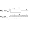
- FIG. 3A is a top view of the puncture needle used in the second embodiment of the present invention
- FIG. 3B is a cross-sectional view of the central portion of the puncture needle
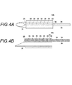
- FIG. 4A is a top view of the puncture needle used in the third embodiment of the present invention
- FIG. 4B is a cross-sectional view of the central portion of the puncture needle.
- FIG. 5A is a top view of a puncture needle used in the fourth embodiment of the present invention
- FIG. 5B is a cross-sectional view of a central portion of the puncture needle.
- FIG. 6A is a top view of the puncture needle used in the fifth embodiment of the present invention, and FIG. 6B is a cross-sectional view of the central portion of the puncture needle.
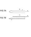
- FIG. 7A is a top view of a puncture needle used in the sixth embodiment of the present invention, and FIG. 7B is a cross-sectional view of the central portion of the puncture needle.
- FIG. 8A is a top view of a puncture needle used in the seventh embodiment of the present invention, and FIG. 8B is a cross-sectional view of the central portion of the puncture needle. Sectional drawing of the center part of the puncture needle of the modification of 7th Embodiment.
- FIG. 1 shows a photoacoustic image generation apparatus according to a first embodiment of the present invention.
- the photoacoustic image generation apparatus 10 includes a probe (ultrasonic probe) 11, an ultrasonic unit 12, and a light source unit 13.
- an ultrasonic wave is used as an acoustic wave.
- the ultrasonic wave is not limited to an ultrasonic wave, and is audible as long as an appropriate frequency is selected in accordance with an object to be examined and measurement conditions.
- An acoustic wave having a frequency may be used.
- the light source unit (light source) 13 is configured as a laser light source, for example.
- the light source unit 13 includes a solid-state laser using, for example, YAG (yttrium / aluminum / garnet) or alexandrite.
- the laser beam emitted from the light source unit 13 is guided to the puncture needle 14 using a light guide means such as an optical fiber. Further, the laser light emitted from the light source unit 13 is guided to the probe 11 using an optical fiber or the like.
- the puncture needle 14 is a needle that is punctured into the subject.
- 2A is a top view of the puncture needle 14 as viewed from above, and
- FIG. 2B is a cross-sectional view of the central portion.
- the puncture needle 14 includes a puncture needle main body 31, a light guide 32, and a tube (tube) 33.
- the puncture needle body 31 has an opening at the tip and is formed in a hollow shape.
- the puncture needle main body 31 is formed, for example, by rounding a metal plate and cutting the tip portion obliquely.
- the light guide 32 is attached to the outer wall on the short side (short side) of the puncture needle body 31 whose tip is cut obliquely.
- the light guide 32 extends along the longitudinal direction of the puncture needle body 31.
- the light guide 32 is formed of, for example, a high refractive material glass or resin.
- the light guide 32 is optically coupled to a light emitting end of an optical fiber that guides light from the light source unit 13 (see FIG. 1) to the puncture needle 14, for example.
- the light guide 32 emits light at least partially toward the puncture needle body 31 while guiding light from the light source unit 13 toward the distal end of the puncture needle body 31. 2A and 2B, the light guide 32 emits light toward the puncture needle body 31 in the entire longitudinal direction of the puncture needle body 31.
- the light guide 32 is disposed outside the hollow puncture needle body 31.
- the tube 33 is a hollow tube that covers the puncture needle body 31 and the light guide 32.
- the tube 33 is made of a fluororesin such as PTFE (polytetrafluoroethylene).
- the diameter of the tube 33 is slightly larger than the diameter (outer diameter) of the puncture needle body 31, for example.
- the tube 33 has a characteristic of transmitting acoustic waves. 2B shows an example in which the tube 33 is disposed so that the center of the puncture needle body 31 and the center of the tube 33 coincide with each other, it is not necessary that the centers of the two coincide.
- the puncture needle main body 31 and the tube 33 may be in contact with the side opposite to the side where the light guide 32 of the puncture needle main body 31 is provided.
- the probe 11 is an acoustic wave detecting means, and has, for example, a plurality of ultrasonic transducers arranged one-dimensionally.
- the probe 11 detects a photoacoustic wave generated in the subject.
- the photoacoustic wave detected by the probe 11 is caused by the photoacoustic wave generated due to the light emitted from the probe 11 and the light emitted from the light guide 32 (see FIGS. 2A and 2B) of the puncture needle 14.
- a photoacoustic wave generated in the puncture needle main body 31 In addition to the detection of the photoacoustic wave, the probe 11 may detect the output of the acoustic wave (ultrasound) to the subject and the reflected acoustic wave (reflected ultrasound) from the subject with respect to the transmitted ultrasound. .
- the ultrasonic unit 12 includes a reception circuit 21, a reception memory 22, and a photoacoustic image generation unit 23.
- the receiving circuit 21 receives a photoacoustic wave detection signal (photoacoustic signal) detected by the probe 11.
- the received photoacoustic signal is converted into a digital signal by an analog-to-digital converter (not shown) or the like and stored in the reception memory 22.
- the photoacoustic image generation means 23 reads a photoacoustic signal from the reception memory 22 and generates a photoacoustic image based on the photoacoustic signal.
- the generation of the photoacoustic image includes, for example, image reconstruction such as phase matching addition, detection / logarithmic conversion, and the like.
- the generated photoacoustic image is displayed on an image display means such as a display (not shown).
- the ultrasonic unit 12 may further include an ultrasonic image generation unit that generates an ultrasonic image based on a detection signal (reflected ultrasonic signal) of the reflected ultrasonic wave detected by the probe 11.
- the puncture needle 14 is punctured by, for example, a doctor from the surface of the subject. After puncturing with the puncture needle 14, laser light is emitted from the light source unit 13. The light emitted from the light source unit 13 enters the light guide 32 through an optical fiber or the like. The light incident on the light guide 32 is guided by the light guide 32 toward the distal end of the puncture needle body 31. At this time, light leaking from the light guide 32 is applied to the puncture needle body 31. In the puncture needle main body 31, a photoacoustic wave resulting from the light emitted from the light guide 32 is generated.
- the light emitted from the light source unit 13 is guided to the probe 11 and emitted from the probe 11 toward the subject.
- a photoacoustic wave resulting from the light emitted from the probe 11 is generated in the subject.
- the light emission to the subject is not necessarily performed from the probe 11, and the light emission may be performed from a place other than the probe 11.
- the light emission from the probe 11 and the light emission from the light guide of the puncture needle 14 do not necessarily have to be performed simultaneously, and both may be performed separately.
- both need not be the same light source, and a light source that emits light to the probe 11 and a light source that emits light to the light guide of the puncture needle 14 may be separated.
- the wavelength of the light emitted from the probe 11 and the wavelength of the light emitted from the light guide 32 do not have to be the same, and the wavelength of the light emitted from the probe 11 and the wavelength of the light emitted from the light guide 32 are: Different wavelengths may be used.
- the probe 11 detects a photoacoustic wave generated in the subject by the irradiation of the laser beam.
- the receiving circuit 21 receives a photoacoustic signal from the probe 11, and the receiving memory 22 stores the photoacoustic signal.
- the photoacoustic image generation unit 23 generates a photoacoustic image based on the photoacoustic signal.
- the distribution of the light absorber in the subject and the portion of the puncture needle body 31 are imaged by the photoacoustic image.
- the generated photoacoustic image is displayed on an image display means or the like.
- a light guide that extends along the longitudinal direction of the puncture needle main body 31 to the puncture needle 14 and emits the light from the light source unit 13 toward the puncture needle main body 31 while guiding the light from the distal direction. 32 is provided.
- the puncture needle body 31 is irradiated with light along the longitudinal direction of the puncture needle body 31 from the light guide 32, the puncture needle 14 is punctured at a deep position, and light from the surface does not reach the puncture needle 14
- a photoacoustic wave can be generated in the puncture needle body 31.
- photoacoustic waves can be generated from the entire long and thin puncture needle 14.
- the puncture needle body 31 and the light guide 32 are covered with a tube 33.
- the light guide 32 By covering the light guide 32 with the tube 33, the light guide 32 can be firmly fixed to the puncture needle body 31.
- the photoacoustic wave generated in the puncture needle main body 31 propagates to the subject through the tube 33.
- the presence of the tube 33 made of a fluororesin between the puncture needle body 31 made of metal and the subject (water) can reduce the difference in acoustic impedance between the metal and water.
- the photoacoustic wave generated in the puncture needle body 31 can be easily transmitted to the subject.
- by forming the tube 33 with a fluororesin it is possible to improve the sliding of the needle surface as compared with the case where the puncture needle body 31 is directly punctured into the subject.
- FIG. 3A is a top view of the puncture needle used in the second embodiment of the present invention
- FIG. 3B is a cross-sectional view of the central portion of the puncture needle.
- the light guide 32 is composed of an optical fiber from which the clad 34 has been removed.
- the optical fiber is part of an optical wiring that guides light from the light source unit 13 to the puncture needle 14a.
- the cladding that surrounds the core of the optical fiber is removed.
- the optical fiber cladding 34 is not removed from the portion connected to the light source unit 13 to the puncture needle body 31, and the optical fiber cladding 34 is removed at the portion where the puncture needle body 31 and the optical fiber are in contact to expose the core. .
- This core constitutes the light guide 32.
- the clad 34 does not have to be completely removed in the circumferential direction of the optical fiber, and at least the puncture needle body 31 side only needs to be removed.
- light is guided to the puncture needle 14a using an optical fiber, and light is transmitted to the puncture needle main body 31 using the optical fiber core as the light guide 32 at a portion where the puncture needle main body 31 and the optical fiber are in contact with each other. Exit. With such a configuration, light can be guided efficiently and stably to the light guide portion. Other effects are the same as those of the first embodiment.
- FIG. 4A is a top view of the puncture needle used in the third embodiment of the present invention
- FIG. 4B is a cross-sectional view of the central portion of the puncture needle.
- the second embodiment shown in FIGS. 3A and 3B is that the clad 34 is not completely removed but partially removed at the portion where the puncture needle body 31 and the optical fiber are in contact. It differs from the form.
- the optical fiber cladding 34 is removed at a plurality of locations along the extending direction.
- the clad 34 is removed at a predetermined interval, and exposed portions 35 where the core (light guide 32) is exposed from the clad 34 are formed at a predetermined interval.
- Light is irradiated to the puncture needle body 31 from the exposed portion 35 formed in the optical fiber.
- the exposed portions 35 do not have to be arranged at equal intervals along the extending direction of the optical fiber (longitudinal direction of the puncture needle body 31). For example, the closer to the tip of the puncture needle 14b, the shorter the interval. Good.
- the clad 34 of the optical fiber that guides the light emitted from the light source unit 13 to the puncture needle 14b is removed at a plurality of locations, and a plurality of exposed portions 35 are formed along the longitudinal direction of the puncture needle 14b. .
- Part of the light traveling through the light guide 32 toward the distal end of the puncture needle 14 b leaks from the exposed portion 35 and is irradiated onto the puncture needle main body 31.
- photoacoustic waves can be generated discretely along the longitudinal direction of the puncture needle 14b.
- Other effects are the same as those of the second embodiment.
- FIG. 5A is a top view of the puncture needle used in the fourth embodiment of the present invention
- FIG. 5B is a cross-sectional view of the central portion of the puncture needle.
- the puncture needle 14c of this embodiment is different from the first embodiment shown in FIGS. 2A and 2B in that the light guide 32 and the tube 33 are bonded to the puncture needle body 31 using an adhesive 36.
- the adhesive 36 is applied to the outer peripheral portion of the puncture needle body 31, and the light guide 32 and the tube 33 are bonded and fixed to the puncture needle body 31.
- an adhesive having light absorption is used as the adhesive 36.
- a black pigment is mixed in the adhesive 36.
- the light emitted from the light guide 32 toward the puncture needle body 31 is absorbed by the adhesive 36 having a light absorption property, and a photoacoustic wave is generated therefrom.
- the adhesive 36 does not necessarily have to be applied to the entire outer periphery of the puncture needle body 31, and may be applied to at least the periphery of the light guide 32.
- the light guide 32 and the tube 33 are fixed using an adhesive 36 having a light absorption property.
- a photoacoustic wave can be generated in the puncture needle main body 31 and the adhesive 36, and a photoacoustic wave can be generated efficiently.
- Other effects are the same as those of the first embodiment.
- FIG. 6A is a top view of a puncture needle used in the fifth embodiment of the present invention
- FIG. 6B is a cross-sectional view of a central portion of the puncture needle.
- the puncture needle 14d of the present invention is different from the third embodiment shown in FIGS. 4A and 4B in that the light guide 32 and the tube 33 are bonded to the puncture needle body 31 using an adhesive 36.
- an adhesive 36 an adhesive having light absorption is used as in the fourth embodiment.
- the photoacoustic wave generated discretely can be strengthened as compared with the third embodiment. Other effects are the same as those of the third embodiment.
- FIG. 7A is a top view of the puncture needle used in the sixth embodiment of the present invention
- FIG. 7B is a cross-sectional view of the central portion of the puncture needle.
- the puncture needle 14e of this embodiment is different from the first embodiment in that the tube 33 (see FIGS. 2A and 2B) is not provided. Other points are the same as in the first embodiment. Even when the tube 33 is not provided, similarly to the first embodiment, the light guide 32 can irradiate the puncture needle body 31 along the longitudinal direction of the puncture needle body 31, and the puncture needle 14e Even when puncture is performed at a deep position, the position of the puncture needle 14e can be confirmed by a photoacoustic image.
- FIG. 8A is a top view of the puncture needle used in the seventh embodiment of the present invention
- FIG. 8B is a cross-sectional view of the central portion of the puncture needle.
- the puncture needle 14f of this embodiment is different from the sixth embodiment shown in FIGS. 7A and 7B in that the light guide 32 is disposed inside the puncture needle body 31. Other points may be the same as in the sixth embodiment.
- the present embodiment is the same as the sixth embodiment except that the position where the light guide 32 is attached is the inner wall of the hollow puncture needle body 31, and the obtained effect is the same as that of the sixth embodiment. .
- the above embodiments can be used in appropriate combination.
- the second embodiment in which the optical fiber cladding 34 is removed at the portion of the puncture needle body 31 and the sixth embodiment in which the tube 33 covering the puncture needle body 31 and the light guide 32 is omitted are combined, and FIGS. 3A and 3B are combined.
- the tube 33 may be omitted.
- the third embodiment and the sixth embodiment in which light is radiated from the light guide 32 to the puncture needle body 31 in a discrete manner may be combined, and the tube 33 may be omitted in FIGS. 4A and 4B.
- the fourth and fifth embodiments using the light-absorbing adhesive 36 are combined with the sixth embodiment, and the tubes 33 are omitted in FIGS. 5A and 5B, and FIGS. 6A and 6B, respectively. It is good also as a structure.
- the seventh embodiment in which the light guide 32 is provided inside the puncture needle body 31, light is guided to the portion of the puncture needle body 31 through the optical fiber as in the second embodiment (see FIGS. 3A and 3B).
- the optical fiber cladding 34 may be removed to expose the core portion, and the optical fiber core may be used as the light guide 32.
- the optical fiber clad is exposed at a plurality of locations in the longitudinal direction of the puncture needle body 31, and the puncture needle is moved from the light guide 32.
- the main body 31 may be irradiated with light discretely.
- FIG. 9 shows a cross section near the center of the puncture needle in which the fourth embodiment and the seventh embodiment are combined.
- an adhesive 36 having a light absorption property is applied to the inner wall of the puncture needle body 31.
- the light guide 32 is bonded and fixed to the inner wall of the puncture needle body 31 by an adhesive 36.
- the adhesive 36 does not need to be applied to the entire inner wall of the puncture needle main body 31, and may be applied to at least a portion where the light guide 32 is bonded and fixed.
- the tip of the light guide 32 may be cut obliquely in the same angle and direction as the tip of the puncture needle 14. In this case, since the light emitted from the tip of the light guide is directed toward the puncture needle body 31, the photoacoustic signal generated at the tip can be strengthened.
- the light guide 32 may be cut in the direction opposite to the case where the light guide 32 is arranged outside.
- the photoacoustic image generation apparatus and puncture needle of this invention are not limited only to the said embodiment, Various from the structure of the said embodiment. Modifications and changes are also included in the scope of the present invention.
Landscapes
- Health & Medical Sciences (AREA)
- Life Sciences & Earth Sciences (AREA)
- Surgery (AREA)
- Medical Informatics (AREA)
- Veterinary Medicine (AREA)
- Pathology (AREA)
- Public Health (AREA)
- Engineering & Computer Science (AREA)
- Biomedical Technology (AREA)
- Heart & Thoracic Surgery (AREA)
- General Health & Medical Sciences (AREA)
- Molecular Biology (AREA)
- Animal Behavior & Ethology (AREA)
- Nuclear Medicine, Radiotherapy & Molecular Imaging (AREA)
- Physics & Mathematics (AREA)
- Biophysics (AREA)
- Radiology & Medical Imaging (AREA)
- Ultra Sonic Daignosis Equipment (AREA)
- Surgical Instruments (AREA)
- Acoustics & Sound (AREA)
Abstract
本発明は、穿刺針が被検体の表面から深い位置に穿刺された場合でも、光音響画像上で穿刺針そのものの位置を確認可能な光音響計測装置を提供する。また、本発明は、そのような光音響画像生成装置に用いられる穿刺針を提供する。穿刺針14は、先端に開口を有する中空形状の針である。穿刺針14は、穿刺針本体31と、ライトガイド32とを有する。ライトガイド32は、穿刺針本体の長手方向に沿って延在する。ライトガイド32は、光源からの光を先端方向に導光しつつ、穿刺針本体31に向けて少なくとも部分的に光を出射する。
Description
本発明は、光音響計測装置に関し、更に詳しくは、被検体に対する光出射後に光出射に起因して生じた光音響波に基づいて光音響画像を生成する光音響画像生成装置に関する。また、本発明は、そのような光音響画像生成装置に用いられる穿刺針に関する。
生体内部の状態を非侵襲で検査できる画像検査法の一種として、超音波検査法が知られている。超音波検査では、超音波の送信及び受信が可能な超音波探触子を用いる。超音波探触子から被検体(生体)に超音波を送信させると、その超音波は生体内部を進んでいき、組織界面で反射する。超音波探触子でその反射音波を受信し、反射超音波が超音波探触子に戻ってくるまでの時間に基づいて距離を計算することで、内部の様子を画像化することができる。
また、光音響効果を利用して生体の内部を画像化する光音響イメージングが知られている。一般に光音響イメージングでは、レーザパルスなどのパルスレーザ光を生体内に照射する。生体内部では、生体組織がパルスレーザ光のエネルギーを吸収し、そのエネルギーによる断熱膨張により超音波(光音響波)が発生する。この光音響波を超音波プローブなどで検出し、検出信号に基づいて光音響画像を構成することで、光音響波に基づく生体内の可視化が可能である。
ここで、特許文献1には、光音響を用いた生体情報イメージングと穿刺針を用いた処置との組み合わせが言及されている。特許文献1では、光音響画像を生成し、その画像を観察することで、腫瘍などの患部や、患部の疑いがある部位などを見つける。そのような部位をより精密に検査するために、或いは患部に注射などを行うために、注射針や細胞診針等の穿刺針を用いて、細胞を採取や患部への注射などを行う。特許文献1では、光音響画像を用いて、患部を観察しながら穿刺を行うことができるとしている。
光音響イメージングでは、通常、被検体に対する光照射は被検体の表面から行われる。特に、穿刺針の先端が深い位置まで穿刺されると、被検体表面からの照射光が深い位置に穿刺された穿刺針まで十分に届かず、光音響画像で穿刺針の位置を確認することが困難になる。この問題に対し、特許文献2には、穿刺針に発光部を設け、その発光部から光出射を行うことが記載されている。発光部は、例えば穿刺針の先端方向に向かって厚みが減少するように形成された導光部材で構成される。
特許文献2では、被検体への穿刺針の穿刺後に発光部から光出射を行い、被検体内の光吸収体が、穿刺針の発光部から出射した光を吸収することで発生する光音響波を検出する。その光音響波に基づいて光音響画像が生成される。特許文献2では、光音響画像上で、発光部から光が照射された場所を認識することができ、穿刺針が存在する位置を確認することができる。しかしながら、特許文献2では、発光部から被検体に対して光出射を行っており、光音響信号を発生するのは被検体内の光吸収体である。このため、針そのものの位置を確認することが困難な場合がある。
本発明は、上記に鑑み、穿刺針が被検体の表面から深い位置に穿刺された場合でも、光音響画像上で穿刺針そのものの位置を確認可能な光音響画像生成装置を提供することを目的とする。
また、本発明は、そのような光音響画像生成装置に用いられる穿刺針を提供することを目的とする。
上記目的を達成するために、本発明は、先端に開口を有する中空の穿刺針本体と、穿刺針本体の長手方向に沿って延在し、光源からの光を先端方向に導光しつつ、穿刺針本体に向けて少なくとも部分的に光を出射するライトガイドとを備えたことを特徴とする穿刺針を提供する。
本発明において、ライトガイドは穿刺針本体の外側に配置されていてもよい。
本発明では、穿刺針が、穿刺針本体及びライトガイドを覆う管を更に備えていてもよい。ライトガイドを覆う管は、例えばフッ素樹脂で形成できる。
上記に代えて、ライトガイドを穿刺針本体の内側に配置してもよい。
ライトガイドは、光吸収性を有する接着剤により穿刺針本体に接着されていてもよい。
ライトガイドは、穿刺針本体と接する部分において少なくとも部分的にクラッドが除去された光ファイバを含んでいてもよい。この場合において、クラッドは、延在方向に沿った複数の箇所で除去されていてもよい。また、クラッドが所定間隔で除去されていてもよい。
ライトガイドに含まれる光ファイバは、光源からの光を穿刺針まで導光する光配線の一部であってもよい。
本発明は、また、光源と、先端に開口を有する中空の穿刺針本体と、該穿刺針本体の長手方向に沿って延在し、光源からの光を先端方向に導光しつつ、穿刺針本体に向けて少なくとも部分的に光を出射するライトガイドとを有する穿刺針と、ライトガイドから光が出射された後に被検体内で発生した光音響波を検出する音響波検出手段と、光音響波の検出信号に基づいて光音響画像を生成する光音響画像生成手段とを備えたことを特徴とする光音響画像生成装置を提供する。
本発明の光音響画像生成装置では、穿刺針に、穿刺針本体の長手方向に沿って延在し、光源からの光を先端方向に導光しつつ、穿刺針本体に向けて少なくとも部分的に光を出射するライトガイドが設けられる。本発明では、ライトガイドから穿刺針の長手方向に沿って穿刺針本体に向けて光出射しており、穿刺針本体の、光が照射された部分から光音響波が生じる。穿刺針に光出射を行うライトガイドが設けられているため、穿刺針が被検体の表面から深い位置に穿刺された場合でも、穿刺針において光音響波を生じさせることができる。また、検出された光音響波に基づいて光音響画像を生成することで、穿刺針そのものの位置を確認できる。
以下、図面を参照し、本発明の実施の形態を詳細に説明する。図1は、本発明の第1実施形態の光音響画像生成装置を示す。光音響画像生成装置10は、プローブ(超音波探触子)11と、超音波ユニット12と、光源ユニット13とを含む。なお、本発明の実施形態では、音響波として超音波を用いるが、超音波に限定されるものでは無く、被検対象や測定条件等に応じて適切な周波数を選択してさえいれば、可聴周波数の音響波を用いても良い。
光源ユニット(光源)13は、例えばレーザ光源として構成される。光源ユニット13は、例えばYAG(イットリウム・アルミニウム・ガーネット)やアレキサンドライトなどを用いた固体レーザを含む。光源ユニット13から出射したレーザ光は、例えば光ファイバなどの導光手段を用いて穿刺針14まで導光される。また、光源ユニット13から出射したレーザ光は、光ファイバなどを用いてプローブ11にまで導光される。
穿刺針14は、被検体内に穿刺される針である。図2Aは穿刺針14を上から見た上面図であり、図2Bは中心部分の断面図である。穿刺針14は、穿刺針本体31と、ライトガイド32と、チューブ(管)33とを有する。穿刺針本体31は、先端に開口を有し、中空形状に形成される。穿刺針本体31は、例えば金属の板を丸め、先端部分を斜めにカットすることで形成される。穿刺針本体31の形成後、先端部分が斜めにカットされた穿刺針本体31の短い側(短辺側)の外壁に、ライトガイド32が取り付けられる。
ライトガイド32は、穿刺針本体31の長手方向に沿って延在する。ライトガイド32は、例えば高屈折材料のガラスや樹脂などで形成される。ライトガイド32は、例えば光源ユニット13(図1参照)からの光を穿刺針14まで導光する光ファイバの光出射端と光学的に結合されている。ライトガイド32は、光源ユニット13からの光を穿刺針本体31の先端方向に導光しつつ、穿刺針本体31に向けて少なくとも部分的に光を出射する。図2A及び図2Bでは、ライトガイド32は、穿刺針本体31の長手方向の全体で、穿刺針本体31に向けて光を出射する。ライトガイド32は、中空形状の穿刺針本体31の外側に配置されている。
チューブ33は、穿刺針本体31及びライトガイド32を覆う中空の管である。チューブ33は、例えばPTFE(polytetrafluoroethylene)などのフッ素樹脂で形成される。チューブ33の直径は、例えば穿刺針本体31の直径(外径)よりも少しだけ大きい。
チューブ33は、音響波を透過させる特性を持つ。なお、図2Bでは、穿刺針本体31とチューブ33の中心とが一致するようにチューブ33を配置する例を示しているが、両者の中心が一致している必要はない。例えば穿刺針本体31のライトガイド32が設けられた側と反対側において、穿刺針本体31とチューブ33とが接触していてもよい。
チューブ33は、音響波を透過させる特性を持つ。なお、図2Bでは、穿刺針本体31とチューブ33の中心とが一致するようにチューブ33を配置する例を示しているが、両者の中心が一致している必要はない。例えば穿刺針本体31のライトガイド32が設けられた側と反対側において、穿刺針本体31とチューブ33とが接触していてもよい。
図1に戻り、プローブ11は、音響波検出手段であり、例えば一次元的に配列された複数の超音波振動子を有している。プローブ11は、被検体内で発生した光音響波を検出する。プローブ11が検出する光音響波は、プローブ11から出射した光に起因して発生した光音響波と、穿刺針14のライトガイド32(図2A及び図2B参照)から出射した光に起因して穿刺針本体31で発生した光音響波とを含む。プローブ11は、光音響波の検出に加えて、被検体に対する音響波(超音波)の出力、及び送信した超音波に対する被検体からの反射音響波(反射超音波)の検出を行ってもよい。
超音波ユニット12は、受信回路21、受信メモリ22、及び光音響画像生成手段23を有する。受信回路21は、プローブ11で検出された光音響波の検出信号(光音響信号)を受信する。受信された光音響信号は、図示しないAD変換器(analog to digital converter)などでデジタル信号に変換され、受信メモリ22に格納される。光音響画像生成手段23は、受信メモリ22から光音響信号を読み出し、光音響信号に基づいて光音響画像を生成する。光音響画像の生成は、例えば、位相整合加算などの画像再構成や、検波・対数変換などを含む。生成された光音響画像は、図示しない、ディスプレイなどの画像表示手段に表示される。超音波ユニット12は、プローブ11で検出された反射超音波の検出信号(反射超音波信号)に基づいて超音波画像を生成する超音波画像生成手段を更に備えていてもよい。
穿刺針14は、医師などにより、例えば被検体の表面から穿刺される。穿刺針14の穿刺後、光源ユニット13からレーザ光を出射する。光源ユニット13から出射した光は、光ファイバなどを通してライトガイド32に入射する。ライトガイド32に入射した光は、ライトガイド32によって穿刺針本体31の先端方向に導光される。このとき、ライトガイド32から漏れ出た光が穿刺針本体31に照射される。穿刺針本体31では、ライトガイド32から出射された光に起因する光音響波が生じる。
また、光源ユニット13から出射した光は、プローブ11まで導光され、プローブ11から被検体方向に出射される。被検体内では、プローブ11から出射された光に起因する光音響波が生じる。
なお、被検体に対する光出射は、必ずしもプローブ11から行う必要はなく、プローブ11以外の場所から光出射を行うこととしてもよい。また、プローブ11からの光出射と穿刺針14のライトガイドからの光出射とは、必ずしも同時に行う必要はなく、両者を別々に行ってもよい。また、両者は同一光源である必要はなく、プローブ11に対して光出射を行う光源と、穿刺針14のライトガイドに対して光出射を行う光源とを分けてもよい。プローブ11から出射する光の波長と、ライトガイド32から出射する光の波長とは、同一である必要はなく、プローブ11から出射する光の波長とライトガイド32から出射する光の波長とを、異なる波長にしてもよい。
プローブ11は、レーザ光の照射により被検体内で発生した光音響波を検出する。受信回路21はプローブ11から光音響信号を受信し、受信メモリ22には光音響信号が格納される。光音響画像生成手段23は、光音響信号に基づいて光音響画像を生成する。光音響画像により、被検体内の光吸収体の分布と、穿刺針本体31の部分とが画像化される。生成された光音響画像は、画像表示手段などに表示される。
本実施形態では、穿刺針14に、穿刺針本体31の長手方向に沿って延在し、光源ユニット13からの光を先端方向に導光しつつ、穿刺針本体31に向けて出射するライトガイド32を設ける。ライトガイド32から穿刺針本体31の長手方向に沿って穿刺針本体31に対して光照射を行うことで、穿刺針14が深い位置に穿刺され、表面からの光が穿刺針14に届かない場合でも、穿刺針本体31において光音響波を発生できる。また、ライトガイド32から長手方向に沿った全体で穿刺針本体31に光照射を行うことで、長細い穿刺針14の全体から光音響波を発生できる。検出された光音響波に基づいて光音響画像を生成することで、光音響画像により穿刺針14を画像化でき、穿刺針の位置を確認することが可能である。
また、本実施形態では、穿刺針本体31及びライトガイド32をチューブ33で覆っている。チューブ33がライトガイド32を覆うことで、ライトガイド32を強固に穿刺針本体31へ固定することが可能である。また、穿刺針本体31で発生した光音響波は、チューブ33を介して被検体へ伝搬する。金属で形成された穿刺針本体31と被検体(水分)との間にフッ素樹脂で形成されたチューブ33が存在することで、金属と水との間の音響インピーダンスの差を軽減することができ、穿刺針本体31で発生した光音響波を被検体に伝えやすくできる。また、チューブ33をフッ素樹脂で形成することで、穿刺針本体31を直接被検体に穿刺する場合に比べて、針表面のすべりをよくすることができる。
続いて、本発明の第2実施形態を説明する。図3Aは本発明の第2実施形態で用いられる穿刺針の上面図であり、図3Bは穿刺針の中心部分の断面図である。本実施形態の穿刺針14aでは、ライトガイド32は、クラッド34が除去された光ファイバで構成される。また、その光ファイバは、光源ユニット13からの光を穿刺針14aまで導光する光配線の一部である。
光源ユニット13からの光を穿刺針14aまで導光する光ファイバの先端部分において、光ファイバのコアを取り囲むクラッド部分を除去する。光源ユニット13と接続される部分から穿刺針本体31までは光ファイバのクラッド34を除去せず、穿刺針本体31と光ファイバが接する部分において光ファイバのクラッド34を除去してコアをむき出しにする。このコアがライトガイド32を構成する。クラッド34は、光ファイバの周方向に全て除去されている必要はなく、少なくとも穿刺針本体31側が除去されていればよい。
本実施形態では、光ファイバを用いて穿刺針14aまで光を導光し、穿刺針本体31と光ファイバが接する部分では、光ファイバのコアをライトガイド32として用いて穿刺針本体31へ光を出射する。このような構成とすることで、ライトガイド部分まで効率よく、安定して光を導光することができる。その他の効果は第1実施形態と同様である。
次いで、本発明の第3実施形態を説明する。図4Aは本発明の第3実施形態で用いられる穿刺針の上面図であり、図4Bは穿刺針の中心部分の断面図である。本実施形態の穿刺針14bでは、穿刺針本体31と光ファイバが接する部分においてクラッド34が全面的に除去されず、部分的に除去されている点で、図3A及び図3Bに示す第2実施形態と相違する。
本実施形態では、光ファイバのクラッド34を、延在方向に沿った複数の箇所で除去している。例えば、クラッド34を所定間隔で除去し、クラッド34からコア(ライトガイド32)が露出する露出部分35を所定間隔で形成する。光ファイバに形成された露出部分35から、穿刺針本体31に対して光が照射される。露出部分35は、光ファイバの延在方向(穿刺針本体31の長手方向)に沿って等間隔に並んでいる必要はなく、例えば穿刺針14bの先端に近くなるほど間隔が短くなるようにしてもよい。
本実施形態では、光源ユニット13から出射した光を穿刺針14bまで導光する光ファイバのクラッド34を複数の箇所で除去し、穿刺針14bの長手方向に沿って複数の露出部分35を形成する。ライトガイド32を穿刺針14bの先端方向に進行する光の一部は、露出部分35から漏れ出て穿刺針本体31に照射される。本実施形態では、穿刺針本体31に対して離散的に光照射を行うため、穿刺針14bの長手方向にそって離散的に光音響波を発生させることができる。その他の効果は第2実施形態と同様である。
引き続いて、本発明の第4実施形態を説明する。図5Aは本発明の第4実施形態で用いられる穿刺針の上面図であり、図5Bは穿刺針の中心部分の断面図である。本実施形態の穿刺針14cは、接着剤36を用いてライトガイド32及びチューブ33が穿刺針本体31に接着されている点で、図2A及び図2Bに示した第1実施形態と相違する。
例えば、穿刺針本体31の外周部分に接着剤36が塗布され、ライトガイド32及びチューブ33が穿刺針本体31に接着固定される。接着剤36には、光吸収性を有する接着剤が用いられる。接着剤36には、例えば黒い顔料が混合されている。ライトガイド32から穿刺針本体31に向けて出射した光は、光吸収性を有する接着剤36で吸収され、そこから光音響波が発生する。接着剤36は、必ずしも穿刺針本体31の外周の全てに塗布されている必要なく、少なくともライトガイド32の周辺に塗布されていればよい。
本実施形態では、光吸収性を有する接着剤36を用いてライトガイド32及びチューブ33が固定されている。本実施形態では、穿刺針本体31及び接着剤36において光音響波を発生させることができ、効率よく光音響波を発生させることができる。その他の効果は第1実施形態と同様である。
次いで、本発明の第5実施形態を説明する。図6Aは本発明の第5実施形態で用いられる穿刺針の上面図であり、図6Bは穿刺針の中心部分の断面図である。本発明の穿刺針14dは、接着剤36を用いてライトガイド32及びチューブ33が穿刺針本体31に接着されている点で、図4A及び図4Bに示した第3実施形態と相違する。接着剤36には、第4実施形態と同様に光吸収性を有する接着剤が用いられる。光吸収性を有する接着剤36が用いられることで、第3実施形態と比べて、離散的に発生させる光音響波を強めることができる。その他の効果は第3実施形態と同様である。
さらに、本発明の第6実施形態を説明する。図7Aは本発明の第6実施形態に用いられる穿刺針の上面図であり、図7Bは穿刺針の中心部分の断面図である。本実施形態の穿刺針14eは、チューブ33(図2A及び図2B参照)が設けられていない点で、第1実施形態と相違する。その他の点は第1実施形態と同様である。チューブ33が設けられない場合も、第1実施形態と同様に、ライトガイド32から穿刺針本体31の長手方向に沿って穿刺針本体31に対して光照射を行うことができ、穿刺針14eが深い位置に穿刺された場合でも、光音響画像で穿刺針14eの位置が確認可能である。
引き続き、本発明の第7実施形態を説明する。図8Aは本発明の第7実施形態に用いられる穿刺針の上面図であり、図8Bは穿刺針の中心部分の断面図である。本実施形態の穿刺針14fは、ライトガイド32が穿刺針本体31の内側に配置される点で、図7A及び図7Bに示す第6実施形態と相違する。その他の点は第6実施形態と同様でよい。
本実施形態では、ライトガイド32から穿刺針本体31の内壁に対して光が照射され、主に内壁において光音響波が発生する。通常、穿刺針本体31の金属板の厚みは十分に薄く、内壁において発生した光音響波は、多少の減衰は受けるものの十分に被検体内に伝搬可能である。本実施形態は、ライトガイド32が取り付けられる位置が中空形状の穿刺針本体31の内壁である点を除けば、第6実施形態と同様であり、得られる効果も第6実施形態と同様である。
なお、上記各実施形態は、適宜組み合わせて用いることがきる。例えば、穿刺針本体31の部分で光ファイバのクラッド34を除去する第2実施形態と、穿刺針本体31及びライトガイド32を覆うチューブ33を省く第6実施形態とを組み合わせ、図3A及び図3Bにおいてチューブ33を省く構成としてもよい。また、ライトガイド32から穿刺針本体31に離散的に光照射を行う第3実施形態と第6実施形態とを組み合わせ、図4A及び図4Bにおいてチューブ33を省く構成としてもよい。さらには、光吸収性を有する接着剤36を用いる第4実施形態及び第5実施形態と第6実施形態とを組み合わせ、図5A及び図5B、並びに図6A及び図6Bにおいて、それぞれチューブ33を省く構成としてもよい。
また、ライトガイド32を穿刺針本体31の内側に設ける第7実施形態において、第2実施形態(図3A及び図3B参照)と同様に、穿刺針本体31の部分までは光ファイバで光を導光し、穿刺針本体31の部分では、光ファイバのクラッド34を除去してコアの部分を露出させ、光ファイバのコアをライトガイド32としてもよい。また、第7実施形態において、第3実施形態(図4A及び図4B参照)と同様に、光ファイバのクラッドを穿刺針本体31の長手方向の複数の箇所で露出させ、ライトガイド32から穿刺針本体31に離散的に光照射を行ってもよい。
さらに、第7実施形態、及び第7実施形態と第1実施形態から第3実施形態との組み合わせにおいて、第4実施形態と同様に、光吸収性を有する接着剤を用いることもできる。図9に、第4実施形態と第7実施形態とを組み合わせた穿刺針の中心付近の断面を示す。変形例の穿刺針14gでは、穿刺針本体31の内壁に光吸収性を有する接着剤36が塗布されている。ライトガイド32は、接着剤36により、穿刺針本体31の内壁に接着固定される。接着剤36は、穿刺針本体31の内壁の全体に塗布されている必要はなく、少なくともライトガイド32を接着固定する部分に塗布されていればよい。
上記各実施形態では、ライトガイド32の先端部分に特に端面処理が施されない例を説明したが、先端部分に何らかの端面処理を施すことも可能である。例えば、図2Bにおいて、ライトガイド32の先端を、穿刺針14の先端と同様な角度及び方向に斜めにカットしてもよい。この場合、ライトガイドの先端から出射する光は、穿刺針本体31方向に向くため、先端部分で発生する光音響信号を強めることができる。第7実施形態のように、ライトガイド32を穿刺針本体31の内側に設ける場合は、外側に配置する場合とは反対側の方向にカットすればよい。
以上、本発明をその好適な実施形態に基づいて説明したが、本発明の光音響画像生成装置及び穿刺針は、上記実施形態にのみ限定されるものではなく、上記実施形態の構成から種々の修正及び変更を施したものも、本発明の範囲に含まれる。
10:光音響画像生成装置
11:プローブ
12:超音波ユニット
13:光源ユニット
14:穿刺針
21:受信回路
22:受信メモリ
23:光音響画像生成手段
31:穿刺針本体
32:ライトガイド
33:チューブ(管)
34:クラッド
35:露出部分
36:接着剤
11:プローブ
12:超音波ユニット
13:光源ユニット
14:穿刺針
21:受信回路
22:受信メモリ
23:光音響画像生成手段
31:穿刺針本体
32:ライトガイド
33:チューブ(管)
34:クラッド
35:露出部分
36:接着剤
Claims (11)
- 先端に開口を有する中空の穿刺針本体と、
前記穿刺針本体の長手方向に沿って延在し、光源からの光を先端方向に導光しつつ、前記穿刺針本体に向けて少なくとも部分的に光を出射するライトガイドとを備えた穿刺針。 - 前記ライトガイドが前記穿刺針本体の外側に配置される請求項1に記載の穿刺針。
- 前記穿刺針本体及び前記ライトガイドを覆う管を更に備える請求項2に記載の穿刺針。
- 前記管がフッ素樹脂で形成される請求項3に記載の穿刺針。
- 前記ライトガイドが前記穿刺針本体の内側に配置される請求項1に記載の穿刺針。
- 前記ライトガイドが光吸収性を有する接着剤により前記穿刺針本体に接着される請求項1から5何れか1項に記載の穿刺針。
- 前記ライトガイドが、前記穿刺針本体と接する部分において少なくとも部分的にクラッドが除去された光ファイバを含む請求項1から6何れか1項に記載の穿刺針。
- 前記クラッドが延在方向に沿った複数の箇所で除去されている請求項7に記載の穿刺針。
- 前記クラッドが所定間隔で除去されている請求項8に記載の穿刺針。
- 前記光ファイバが、光源からの光を穿刺針まで導光する光配線の一部である請求項7から9何れか1項に記載の穿刺針。
- 光源と、
先端に開口を有する中空の穿刺針本体と、該穿刺針本体の長手方向に沿って延在し、前記光源からの光を先端方向に導光しつつ、前記穿刺針本体に向けて少なくとも部分的に光を出射するライトガイドとを有する穿刺針と、
前記ライトガイドから光が出射された後に被検体内で発生した光音響波を検出する音響波検出手段と、
前記光音響波の検出信号に基づいて光音響画像を生成する光音響画像生成手段とを備えた光音響画像生成装置。
Priority Applications (1)
| Application Number | Priority Date | Filing Date | Title |
|---|---|---|---|
| US14/817,363 US10568603B2 (en) | 2013-03-22 | 2015-08-04 | Photoacoustic measurement device and puncture needle |
Applications Claiming Priority (4)
| Application Number | Priority Date | Filing Date | Title |
|---|---|---|---|
| JP2013059670 | 2013-03-22 | ||
| JP2013-059670 | 2013-03-22 | ||
| JP2014-045922 | 2014-03-10 | ||
| JP2014045922A JP5952327B2 (ja) | 2013-03-22 | 2014-03-10 | 光音響計測装置及び穿刺針 |
Related Child Applications (1)
| Application Number | Title | Priority Date | Filing Date |
|---|---|---|---|
| US14/817,363 Continuation US10568603B2 (en) | 2013-03-22 | 2015-08-04 | Photoacoustic measurement device and puncture needle |
Publications (1)
| Publication Number | Publication Date |
|---|---|
| WO2014148379A1 true WO2014148379A1 (ja) | 2014-09-25 |
Family
ID=51580065
Family Applications (1)
| Application Number | Title | Priority Date | Filing Date |
|---|---|---|---|
| PCT/JP2014/056874 Ceased WO2014148379A1 (ja) | 2013-03-22 | 2014-03-14 | 光音響計測装置及び穿刺針 |
Country Status (3)
| Country | Link |
|---|---|
| US (1) | US10568603B2 (ja) |
| JP (1) | JP5952327B2 (ja) |
| WO (1) | WO2014148379A1 (ja) |
Cited By (4)
| Publication number | Priority date | Publication date | Assignee | Title |
|---|---|---|---|---|
| EP2984985A1 (en) * | 2014-08-11 | 2016-02-17 | PreXion Corporation | Puncture needle for photoacoustic imager |
| WO2017002337A1 (ja) * | 2015-06-30 | 2017-01-05 | 富士フイルム株式会社 | 光音響画像生成装置及び挿入物 |
| JPWO2016158095A1 (ja) * | 2015-03-30 | 2018-01-11 | 富士フイルム株式会社 | 生検針および光音響計測装置 |
| JP2021137377A (ja) * | 2020-03-06 | 2021-09-16 | 株式会社日立製作所 | 超音波発信器具 |
Families Citing this family (7)
| Publication number | Priority date | Publication date | Assignee | Title |
|---|---|---|---|---|
| JP2016036651A (ja) * | 2014-08-11 | 2016-03-22 | プレキシオン株式会社 | 光音響画像化装置用の穿刺針および光音響画像化装置 |
| WO2017002338A1 (ja) * | 2015-06-30 | 2017-01-05 | 富士フイルム株式会社 | 光音響画像生成装置及び挿入物 |
| JP6532329B2 (ja) * | 2015-07-13 | 2019-06-19 | キヤノン株式会社 | 穿刺針およびそれを用いた被検体情報取得装置 |
| JP6595712B2 (ja) | 2016-05-27 | 2019-10-23 | 富士フイルム株式会社 | 固体レーザ装置 |
| JP2019020836A (ja) * | 2017-07-12 | 2019-02-07 | 株式会社コロプラ | 情報処理方法、装置、および当該情報処理方法をコンピュータに実行させるためのプログラム |
| CN111044457B (zh) * | 2019-12-13 | 2021-01-08 | 浙江大学 | 一种农产品内部光分布及内部品质检测多功能装置 |
| WO2024162229A1 (ja) * | 2023-02-02 | 2024-08-08 | テルモ株式会社 | 血管穿刺デバイス及び血管穿刺システム |
Citations (4)
| Publication number | Priority date | Publication date | Assignee | Title |
|---|---|---|---|---|
| WO2011100753A2 (en) * | 2010-02-15 | 2011-08-18 | The Johns Hopkins University | Interventional photoacoustic imaging system |
| EP2548516A1 (en) * | 2011-07-20 | 2013-01-23 | Universiteit Twente | A system for enabling generation of photoacoustic images |
| JP2013013713A (ja) * | 2011-06-07 | 2013-01-24 | Fujifilm Corp | 光音響画像生成装置及び方法 |
| JP2013027513A (ja) * | 2011-07-28 | 2013-02-07 | Fujifilm Corp | 光音響用穿刺針及び光音響画像生成装置 |
Family Cites Families (15)
| Publication number | Priority date | Publication date | Assignee | Title |
|---|---|---|---|---|
| US3657181A (en) * | 1969-08-04 | 1972-04-18 | Minnesota Mining & Mfg | Acoustically transparent composition comprising a thermoplastic polymer and organic fluorine containing compound |
| US4566438A (en) * | 1984-10-05 | 1986-01-28 | Liese Grover J | Fiber-optic stylet for needle tip localization |
| US5280788A (en) * | 1991-02-26 | 1994-01-25 | Massachusetts Institute Of Technology | Devices and methods for optical diagnosis of tissue |
| US6564087B1 (en) * | 1991-04-29 | 2003-05-13 | Massachusetts Institute Of Technology | Fiber optic needle probes for optical coherence tomography imaging |
| DE4403134A1 (de) * | 1993-05-14 | 1995-08-03 | Laser Medizin Zentrum Ggmbh Be | Kombinationsvorrichtung zur thermischen Verödung biologischen Gewebes |
| ES2284218T3 (es) * | 1997-11-12 | 2007-11-01 | Mdc Investment Holdings, Inc. | Dispositivo para la recogida de fluidos con aguja retractil capturada. |
| JP4969761B2 (ja) * | 2000-08-31 | 2012-07-04 | オバン・エナジー・リミテッド | 所望粒度を持つ固体基材の小粒子および第一材料の小粒状物を含む相乗作用性混合物を製造する方法 |
| US7131951B2 (en) * | 2002-03-20 | 2006-11-07 | Board Of Regents, The University Of Texas System | Biopsy needle |
| US20050267555A1 (en) * | 2004-05-28 | 2005-12-01 | Marnfeldt Goran N | Engagement tool for implantable medical devices |
| US7952718B2 (en) * | 2007-05-03 | 2011-05-31 | University Of Washington | High resolution optical coherence tomography based imaging for intraluminal and interstitial use implemented with a reduced form factor |
| JP5349839B2 (ja) * | 2007-06-22 | 2013-11-20 | キヤノン株式会社 | 生体情報イメージング装置 |
| JP5192247B2 (ja) * | 2008-01-29 | 2013-05-08 | 並木精密宝石株式会社 | Octプローブ |
| US20100016844A1 (en) * | 2008-07-21 | 2010-01-21 | Patel Jr Manoj B | Transilluminating foley catheter to facilitate prostate and bladder surgery |
| US8839672B2 (en) * | 2010-10-19 | 2014-09-23 | Board Of Regents, The University Of Texas System | Combined ultrasound and photoacoustic imaging of metal objects |
| US20140378796A1 (en) * | 2011-12-30 | 2014-12-25 | Koninklijke Philips N.V. | System and method for needle navitation using pa effect in us imaging |
-
2014
- 2014-03-10 JP JP2014045922A patent/JP5952327B2/ja not_active Expired - Fee Related
- 2014-03-14 WO PCT/JP2014/056874 patent/WO2014148379A1/ja not_active Ceased
-
2015
- 2015-08-04 US US14/817,363 patent/US10568603B2/en not_active Expired - Fee Related
Patent Citations (4)
| Publication number | Priority date | Publication date | Assignee | Title |
|---|---|---|---|---|
| WO2011100753A2 (en) * | 2010-02-15 | 2011-08-18 | The Johns Hopkins University | Interventional photoacoustic imaging system |
| JP2013013713A (ja) * | 2011-06-07 | 2013-01-24 | Fujifilm Corp | 光音響画像生成装置及び方法 |
| EP2548516A1 (en) * | 2011-07-20 | 2013-01-23 | Universiteit Twente | A system for enabling generation of photoacoustic images |
| JP2013027513A (ja) * | 2011-07-28 | 2013-02-07 | Fujifilm Corp | 光音響用穿刺針及び光音響画像生成装置 |
Cited By (9)
| Publication number | Priority date | Publication date | Assignee | Title |
|---|---|---|---|---|
| EP2984985A1 (en) * | 2014-08-11 | 2016-02-17 | PreXion Corporation | Puncture needle for photoacoustic imager |
| JP2016036683A (ja) * | 2014-08-11 | 2016-03-22 | プレキシオン株式会社 | 光音響画像化装置用の穿刺針および光音響画像化装置 |
| JPWO2016158095A1 (ja) * | 2015-03-30 | 2018-01-11 | 富士フイルム株式会社 | 生検針および光音響計測装置 |
| US10499887B2 (en) | 2015-03-30 | 2019-12-10 | Fujifilm Corporation | Biopsy needle and photoacoustic measurement apparatus |
| WO2017002337A1 (ja) * | 2015-06-30 | 2017-01-05 | 富士フイルム株式会社 | 光音響画像生成装置及び挿入物 |
| JPWO2017002337A1 (ja) * | 2015-06-30 | 2018-01-11 | 富士フイルム株式会社 | 光音響画像生成装置及び挿入物 |
| US10765324B2 (en) | 2015-06-30 | 2020-09-08 | Fujifilm Corporation | Photoacoustic image generation apparatus and insert |
| JP2021137377A (ja) * | 2020-03-06 | 2021-09-16 | 株式会社日立製作所 | 超音波発信器具 |
| JP7348865B2 (ja) | 2020-03-06 | 2023-09-21 | 富士フイルムヘルスケア株式会社 | 超音波発信器具 |
Also Published As
| Publication number | Publication date |
|---|---|
| US10568603B2 (en) | 2020-02-25 |
| US20150335289A1 (en) | 2015-11-26 |
| JP2014207971A (ja) | 2014-11-06 |
| JP5952327B2 (ja) | 2016-07-13 |
Similar Documents
| Publication | Publication Date | Title |
|---|---|---|
| JP5952327B2 (ja) | 光音響計測装置及び穿刺針 | |
| JP5349839B2 (ja) | 生体情報イメージング装置 | |
| CN102596012B (zh) | 生物信息获取装置 | |
| JP5647942B2 (ja) | 光音響撮像装置およびそれに用いられるプローブユニット並びに内視鏡 | |
| JP5647941B2 (ja) | 光音響撮像装置およびそれに用いられるプローブユニット並びに内視鏡 | |
| US9131851B2 (en) | Biological information imaging apparatus and method for analyzing biological information | |
| US8262576B2 (en) | Imaging probe | |
| EP2553425B2 (en) | Photoacoustic imaging apparatus and photoacoustic imaging method | |
| JP5840070B2 (ja) | 光音響計測装置および光音響計測装置用プローブ | |
| JP5635462B2 (ja) | 光音響用穿刺針及び光音響画像生成装置 | |
| US10499887B2 (en) | Biopsy needle and photoacoustic measurement apparatus | |
| JP2013255707A (ja) | 被検体情報取得装置、および、光音響プローブ | |
| JP6000778B2 (ja) | 被検体情報取得装置および被検体情報取得装置の制御方法 | |
| WO2012077356A1 (ja) | 光音響検査用探触子および光音響検査装置 | |
| JP6172912B2 (ja) | 被検体情報取得装置および光音響プローブ | |
| US11344204B2 (en) | Photoacoustic measurement probe and probe unit and photoacoustic measurement apparatus including the same | |
| JP2012173136A (ja) | 光音響撮像装置、それに用いられるプローブユニットおよび光音響撮像装置の作動方法 | |
| JP6396580B2 (ja) | 生検針および光音響計測装置 | |
| JP6532329B2 (ja) | 穿刺針およびそれを用いた被検体情報取得装置 | |
| KR20220153408A (ko) | 피부 내 멜라닌 측정용 자유 스캐닝 펜타입 광음향 단층 센싱 시스템 | |
| JPWO2018061806A1 (ja) | 挿入物およびその挿入物を備えた光音響計測装置並びに挿入物の製造方法 | |
| JP6463414B2 (ja) | 音響波プローブおよび音響波装置 | |
| WO2019044212A1 (ja) | 光音響画像生成装置および画像取得方法 |
Legal Events
| Date | Code | Title | Description |
|---|---|---|---|
| 121 | Ep: the epo has been informed by wipo that ep was designated in this application |
Ref document number: 14770763 Country of ref document: EP Kind code of ref document: A1 |
|
| NENP | Non-entry into the national phase |
Ref country code: DE |
|
| 122 | Ep: pct application non-entry in european phase |
Ref document number: 14770763 Country of ref document: EP Kind code of ref document: A1 |