WO2014148274A1 - 遠心式流体機械 - Google Patents
遠心式流体機械 Download PDFInfo
- Publication number
- WO2014148274A1 WO2014148274A1 PCT/JP2014/055870 JP2014055870W WO2014148274A1 WO 2014148274 A1 WO2014148274 A1 WO 2014148274A1 JP 2014055870 W JP2014055870 W JP 2014055870W WO 2014148274 A1 WO2014148274 A1 WO 2014148274A1
- Authority
- WO
- WIPO (PCT)
- Prior art keywords
- flow path
- pressure side
- pressure
- impeller
- rotor
- Prior art date
Links
Images


Classifications
-
- F—MECHANICAL ENGINEERING; LIGHTING; HEATING; WEAPONS; BLASTING
- F04—POSITIVE - DISPLACEMENT MACHINES FOR LIQUIDS; PUMPS FOR LIQUIDS OR ELASTIC FLUIDS
- F04D—NON-POSITIVE-DISPLACEMENT PUMPS
- F04D17/00—Radial-flow pumps, e.g. centrifugal pumps; Helico-centrifugal pumps
- F04D17/08—Centrifugal pumps
- F04D17/10—Centrifugal pumps for compressing or evacuating
- F04D17/12—Multi-stage pumps
- F04D17/122—Multi-stage pumps the individual rotor discs being, one for each stage, on a common shaft and axially spaced, e.g. conventional centrifugal multi- stage compressors
-
- F—MECHANICAL ENGINEERING; LIGHTING; HEATING; WEAPONS; BLASTING
- F04—POSITIVE - DISPLACEMENT MACHINES FOR LIQUIDS; PUMPS FOR LIQUIDS OR ELASTIC FLUIDS
- F04D—NON-POSITIVE-DISPLACEMENT PUMPS
- F04D29/00—Details, component parts, or accessories
- F04D29/05—Shafts or bearings, or assemblies thereof, specially adapted for elastic fluid pumps
- F04D29/051—Axial thrust balancing
- F04D29/0516—Axial thrust balancing balancing pistons
-
- F—MECHANICAL ENGINEERING; LIGHTING; HEATING; WEAPONS; BLASTING
- F04—POSITIVE - DISPLACEMENT MACHINES FOR LIQUIDS; PUMPS FOR LIQUIDS OR ELASTIC FLUIDS
- F04D—NON-POSITIVE-DISPLACEMENT PUMPS
- F04D29/00—Details, component parts, or accessories
- F04D29/26—Rotors specially for elastic fluids
- F04D29/28—Rotors specially for elastic fluids for centrifugal or helico-centrifugal pumps for radial-flow or helico-centrifugal pumps
- F04D29/284—Rotors specially for elastic fluids for centrifugal or helico-centrifugal pumps for radial-flow or helico-centrifugal pumps for compressors
- F04D29/286—Rotors specially for elastic fluids for centrifugal or helico-centrifugal pumps for radial-flow or helico-centrifugal pumps for compressors multi-stage rotors
-
- F—MECHANICAL ENGINEERING; LIGHTING; HEATING; WEAPONS; BLASTING
- F04—POSITIVE - DISPLACEMENT MACHINES FOR LIQUIDS; PUMPS FOR LIQUIDS OR ELASTIC FLUIDS
- F04D—NON-POSITIVE-DISPLACEMENT PUMPS
- F04D29/00—Details, component parts, or accessories
- F04D29/40—Casings; Connections of working fluid
- F04D29/42—Casings; Connections of working fluid for radial or helico-centrifugal pumps
- F04D29/4206—Casings; Connections of working fluid for radial or helico-centrifugal pumps especially adapted for elastic fluid pumps
-
- F—MECHANICAL ENGINEERING; LIGHTING; HEATING; WEAPONS; BLASTING
- F04—POSITIVE - DISPLACEMENT MACHINES FOR LIQUIDS; PUMPS FOR LIQUIDS OR ELASTIC FLUIDS
- F04D—NON-POSITIVE-DISPLACEMENT PUMPS
- F04D29/00—Details, component parts, or accessories
- F04D29/40—Casings; Connections of working fluid
- F04D29/42—Casings; Connections of working fluid for radial or helico-centrifugal pumps
- F04D29/44—Fluid-guiding means, e.g. diffusers
- F04D29/441—Fluid-guiding means, e.g. diffusers especially adapted for elastic fluid pumps
- F04D29/444—Bladed diffusers
-
- F—MECHANICAL ENGINEERING; LIGHTING; HEATING; WEAPONS; BLASTING
- F05—INDEXING SCHEMES RELATING TO ENGINES OR PUMPS IN VARIOUS SUBCLASSES OF CLASSES F01-F04
- F05D—INDEXING SCHEME FOR ASPECTS RELATING TO NON-POSITIVE-DISPLACEMENT MACHINES OR ENGINES, GAS-TURBINES OR JET-PROPULSION PLANTS
- F05D2250/00—Geometry
- F05D2250/50—Inlet or outlet
- F05D2250/52—Outlet
Definitions
- the present invention relates to a single-shaft multi-stage centrifugal fluid machine.
- centrifugal compressor a single-stage centrifugal compressor is known as a centrifugal fluid machine (see, for example, Patent Document 1).
- This centrifugal compressor includes an impeller attached to a turbine shaft, and a diffuser passage that communicates a discharge side of the impeller and a scroll formed on the outer peripheral side of the impeller.
- the diffuser passage is provided with a guide vane unit including guide vanes, and the guide vane unit is protruded from the diffuser passage or retracted from the diffuser passage by an operation mechanism. Specifically, the guide vane unit is retracted from the diffuser passage when the air chamber on the rear side becomes negative pressure.
- the centrifugal compressor can increase the efficiency by projecting the guide vane unit into the diffuser passage in the low flow rate region, and prevents the efficiency from decreasing by retracting the guide vane unit from the diffuser passage in the high flow rate region. It is out.
- a single-shaft multi-stage centrifugal fluid machine has a low-pressure side fluid working part on one side of a rotor serving as a rotating shaft, a high-pressure side fluid working part, a low-pressure side fluid working part and a high-pressure side on the other side of the rotor.
- a partition wall that partitions the fluid operating unit is provided. Since the partition wall has a low pressure on one side and a high pressure on the other side, the partition wall is easily deformed from high pressure to low pressure.
- the compressed fluid compressed by the high-pressure side fluid working unit flows through the high-pressure side discharge passage formed along the partition wall.
- the discharge channel on the high-pressure side is deformed so that the channel area is expanded when the partition wall is deformed from high pressure to low pressure. If the discharge channel on the high-pressure side widens, the compressed fluid expands when the compressed fluid compressed by the high-pressure side fluid working part flows into the discharge channel, so the work efficiency of the centrifugal fluid machine is greatly reduced. To do.
- Patent Document 1 in order to increase the efficiency in the low flow rate region, the guide vane unit is protruded into the diffuser passage. However, when the partition wall is deformed, the deformation of the discharge passage on the high pressure side is suppressed. It is not possible.
- an object of the present invention is to provide a centrifugal fluid machine that can suppress deformation of the high-pressure side discharge flow path and suppress a decrease in efficiency even if the partition wall is deformed.
- the centrifugal fluid machine includes a rotor, a low-pressure fluid operation unit provided on one axial side of the rotor, a high-pressure fluid operation unit provided on the other axial side of the rotor, and the low-pressure fluid operation.
- the partition wall is provided between the wall and the high pressure side discharge flow path, and is provided between the wall body and the high pressure side discharge flow path.
- an urging means provided between the wall body and the flow path deformation suppressing member and capable of urging the flow path deformation suppressing member toward the high pressure side discharge flow path side.
- the flow path deformation suppressing member is urged toward the high-pressure side discharge flow path by the urging means.
- transformation suppression member can suppress the breadth of the high voltage
- the high-pressure fluid actuating unit has a high-pressure side impeller that supplies a compressed fluid toward the high-pressure side discharge flow path, and the biasing means is downstream of the high-pressure side impeller in the flow direction of the compressed fluid. It is preferable to have an inflow channel for allowing the compressed fluid to flow into the gap between the wall body and the channel deformation suppressing member from the high-pressure side discharge channel.
- the compressed fluid discharged from the high-pressure fluid operating unit is caused to flow into the gap between the wall body and the flow path deformation suppressing member via the inflow flow path, so that the flow path deformation suppressing member is discharged on the high pressure side. It can be biased toward the flow path. For this reason, since the compressed fluid discharged from the high-pressure fluid operating part can be used, the urging force can be increased as the pressure of the compressed fluid increases by the high-pressure fluid operating part. Therefore, the flow path deformation suppressing member can be urged more reliably to the high pressure side discharge flow path side.
- the urging means further includes a reflux flow path for returning the compressed fluid flowing into the gap toward the high pressure side impeller.
- the compressed fluid that has flowed into the gap can be returned to the high-pressure impeller through the return flow path, so that the compressed fluid that flows into the inflow path is not discharged to the outside. A decrease in efficiency can be suppressed.
- the urging means further includes a seal member that seals the reflux flow path.
- the reflux channel can be sealed by the seal member. For this reason, since the inflow to the high voltage
- the biasing means is an elastic member provided in a gap between the wall body and the flow path deformation suppressing member.
- the flow path deformation suppressing member can be biased toward the high pressure side discharge flow path by the elastic member. For this reason, since a compressed fluid does not flow into a clearance gap, the fall of efficiency can be suppressed.
- the urging force by the elastic member is preferably a predetermined urging force that takes into account the deformation of the high-pressure side discharge passage in advance.
- the blowing channel is provided so that the compressed fluid flowing into the gap is blown toward the rotating shaft channel, and the direction in which the compressed fluid is blown is opposite to the rotating direction of the rotor. Preferably it is.
- the swirl flow that flows into the rotation shaft flow path from the high pressure side impeller or the low pressure side impeller side and swirls in the rotation direction of the rotor can be canceled by the compressed fluid blown out from the blow flow path.
- the influence of the vibration of the rotor caused by this swirling flow can be suppressed.
- the high-pressure fluid operation unit includes a high-pressure side impeller that supplies a compressed fluid toward the high-pressure side discharge flow path, and the flow path deformation suppressing member is more than the high-pressure side impeller in the radial direction of the rotor. Is also preferably arranged radially outward.
- the high-pressure side impeller and the flow path deformation suppressing member do not physically interfere with each other in the radial direction of the rotor. It becomes possible to arrange
- a diffuser provided in the high pressure side discharge flow path, wherein the high pressure side discharge flow path is formed by the flow path deformation suppressing member and a flow path forming member facing the flow path deformation suppressing member, It is preferable that both ends of the diffuser are fixed to the flow path deformation suppressing member and the flow path forming member, respectively.
- the diffuser, the flow path deformation suppressing member, and the flow path forming member can be integrated by fixing the flow path deformation suppressing member and the flow path forming member with the diffuser. For this reason, even if the flow path forming member tries to deform in the direction opposite to the low-pressure side impeller, the deformation is regulated by the flow path deformation suppressing member via the diffuser, so that the deformation of the flow path forming member can be suppressed. .
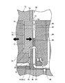
- FIG. 1 is a schematic configuration diagram of a single-shaft multi-stage centrifugal compressor according to a first embodiment.
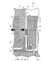
- FIG. 2 is an enlarged view around the partition wall and the high-pressure side discharge passage of the centrifugal compressor according to the first embodiment.
- FIG. 3 is an enlarged view around the partition wall and the high-pressure side discharge passage of the centrifugal compressor according to the second embodiment.
- FIG. 4 is an enlarged view around the partition wall and the high-pressure side discharge passage of the centrifugal compressor according to the third embodiment.
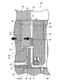
- FIG. 5 is an enlarged view around the partition wall and the high-pressure side discharge flow path of the centrifugal compressor according to the fourth embodiment.
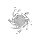
- FIG. 6 is a schematic view around the rotary shaft channel and the outlet channel when viewed from the axial direction of the rotor.
- FIG. 1 is a schematic configuration diagram of a single-shaft multi-stage centrifugal compressor according to the first embodiment.
- a single-shaft multi-stage centrifugal compressor as a centrifugal fluid machine.
- various gases such as air or carbon dioxide are applied as fluids, and the sucked gas is compressed and discharged.
- air is applied as the gas.
- the centrifugal fluid machine is described as being applied to a single-shaft multi-stage centrifugal compressor, but is not limited to this configuration.
- the centrifugal fluid machine may be applied to a single-shaft multi-stage centrifugal pump.
- the centrifugal compressor 1 includes a rotor 5 serving as a rotating shaft, a low-pressure compression unit (low-pressure fluid working unit) 11 serving as a low-pressure stage provided on one side (left side in the drawing) of the rotor 5, and the other side (right side in the drawing). And a high-pressure compression section (high-pressure fluid operation section) 12 serving as a high-pressure stage. Further, the centrifugal compressor 1 is provided between the low pressure compressor 11 and the high pressure compressor 12 in the axial direction of the rotor 5, and a partition wall 13 that partitions the low pressure compressor 11 and the high pressure compressor 12 is provided. Yes.
- the centrifugal compressor 1 has a structure in which the low pressure compressor 11 and the high pressure compressor 12 are back to back with the partition wall 13 interposed therebetween, that is, a substantially symmetrical structure with the partition wall 13 in between. For this reason, the centrifugal compressor 1 cancels out the force (thrust) acting in the axial direction of the rotor 5. Then, the centrifugal compressor 1 compresses air in the low pressure compressor 11, supplies the compressed air compressed in the low pressure compressor 11 to the high pressure compressor 12, further compresses the compressed air in the high pressure compressor 12, The compressed air is discharged.
- the rotor 5 is provided with its axial direction extending in the horizontal direction.
- a power source (not shown) is connected to the rotor 5 and can be rotated by power transmitted from the power source.
- the rotor 5 is fixed with a low pressure side impeller 21 of a low pressure compression unit 11 described later and a high pressure side impeller 41 of a high pressure compression unit 12 described later.
- the low-pressure compression unit 11 includes a plurality of low-pressure side impellers (low-pressure side impellers) 21 fixed to the rotor 5 and low-pressure side housings 22 provided around the plurality of low-pressure side impellers 21.
- the plurality of low-pressure-side impellers 21 are provided in three stages along the axial direction in the first embodiment, and in order from the outside in the axial direction (the left side in the figure), the preceding-stage low-pressure-side impeller 21a, the middle-stage low-pressure-side impeller 21b, A downstream (final stage) low-pressure side impeller 21c is provided.
- the low pressure side impeller 21 includes a hub 25 fixed to the rotor 5, a plurality of blades 26 provided at predetermined intervals in the circumferential direction of the hub 25, and a shroud provided on the opposite side of the hub 25 across the blades 26. 27.
- the low-pressure side impeller 21 is an internal flow path 28 between the hub 25 and the shroud 27 in which air flows from the axial direction to the radial direction, and the upstream side of the internal flow path 28 is the shaft in the air flow direction. It is formed extending in the direction, the downstream side of the internal flow path 28 is formed extending in the radial direction, and the middle of the internal flow path 28 is curved from the axial direction to the radial direction. For this reason, when the low-pressure side impeller 21 rotates, air is sucked in from the axial direction and compressed, and the compressed air compressed is discharged in the radial direction.
- the low-pressure side housing 22 stores the three-stage low-pressure side impeller 21 and one side of the rotor 5 in a freely rotatable manner.
- the low pressure side housing 22 includes a low pressure side air suction port 31, a low pressure side suction flow channel 32, a plurality of low pressure side communication flow channels 33, a low pressure side discharge flow channel 34, and a low pressure side air discharge port 35. Is formed. In FIG. 1, illustration of each flow path formed in the low pressure side housing 22 on the lower side of the rotor 5 is omitted.
- the low-pressure side air suction port 31 is formed on the outer side (the left side in the drawing) in the axial direction and extends from the outer side in the radial direction of the rotor 5 toward the inner side.
- the air sucked from the low pressure side air suction port 31 is supplied toward the low pressure side impeller 21a of the preceding stage.
- One side of the low pressure side suction flow path 32 is connected to the low pressure side air suction port 31, and the other side is connected to the upstream side of the internal flow path 28 of the low pressure side impeller 21 a of the preceding stage.
- the low-pressure side communication channel 33 communicates between the adjacent low-pressure side impellers 21 and is formed in two for the three-stage low-pressure side impellers 21. That is, of the two low-pressure side communication channels 33, one low-pressure side communication channel 33a is downstream of the internal channel 28 in the preceding low-pressure side impeller 21a and the internal channel 28 in the middle-stage low-pressure side impeller 21b. Is connected to the upstream side.
- the other low-pressure side communication flow path 33b connects the downstream side of the internal flow path 28 in the middle-stage low-pressure side impeller 21b and the upstream side of the internal flow path 28 in the downstream-side low-pressure side impeller 21c.
- the low-pressure side air discharge port 35 is formed on the inner side (right side in the drawing) in the axial direction, and extends from the inner side in the radial direction of the rotor 5 to the outer side.
- the low pressure side air discharge port 35 supplies the compressed air discharged from the low pressure side impeller 21 c at the subsequent stage through the low pressure side discharge flow path 34 toward the high pressure compression unit 12.
- the high pressure compressor 12 includes a plurality of high pressure side impellers (high pressure side impellers) 41 fixed to the rotor 5 and a high pressure side housing 42 provided around the plurality of high pressure side impellers 41.
- the plurality of high-pressure side impellers 41 are provided in three stages along the axial direction in the first embodiment, and in order from the outer side (right side in the drawing) in the axial direction, the front-side high-pressure side impeller 41a, the middle-stage high-pressure side impeller 41b, A high-pressure side impeller 41c at the rear stage (final stage) is provided.
- the three-stage low-pressure side impeller 21 and the three-stage high-pressure side impeller 41 are arranged symmetrically in the axial direction.
- the high pressure side impeller 41 has substantially the same configuration as the low pressure side impeller 21, a hub 45 fixed to the rotor 5, and a plurality of blades 46 provided at predetermined intervals in the circumferential direction of the hub 45, And a shroud 47 provided on the opposite side of the hub 45 with the blades 46 interposed therebetween.
- the high-pressure side impeller 41 is an internal flow path 48 between the hub 45 and the shroud 47 in which air flows from the axial direction to the radial direction, and the upstream side of the internal flow path 48 is the shaft in the air flow direction.
- the downstream side of the internal flow path 48 is formed extending in the radial direction, and the middle of the internal flow path 48 is formed curved from the axial direction to the radial direction. For this reason, when the high pressure side impeller 41 rotates, air is sucked in from the axial direction and compressed, and the compressed air compressed is discharged in the radial direction.
- the high-pressure side housing 42 stores the three-stage high-pressure side impeller 41 and the other side of the rotor 5 rotatably.
- the high pressure side housing 42 includes a high pressure side air suction port 51, a high pressure side suction flow channel 52, a plurality of high pressure side communication flow channels 53, a high pressure side discharge flow channel 54, and a high pressure side air discharge port 55. Is formed. In FIG. 1, illustration of each flow path formed in the high-pressure side housing 42 on the lower side of the rotor 5 is omitted.
- the high-pressure side air suction port 51 is formed on the outer side in the axial direction (right side in the drawing), and extends from the outer side in the radial direction of the rotor 5 toward the inner side.
- the compressed air discharged from the low pressure side air discharge port 35 flows into the high pressure side air suction port 51.
- the compressed air that has flowed into the high-pressure side air suction port 51 is supplied toward the high-pressure side impeller 41a at the preceding stage.
- One side of the high-pressure side suction flow path 52 is connected to the high-pressure side air suction port 51, and the other side is connected to the upstream side of the internal flow path 48 of the high-pressure side impeller 41a of the preceding stage.
- the high-pressure side communication channel 53 communicates between the adjacent high-pressure side impellers 41, and two high-pressure side communication channels 53 are formed for the three-stage high-pressure side impellers 41. That is, of the two high-pressure side communication channels 53, one high-pressure side communication channel 53a is downstream of the internal channel 48 in the upstream high-pressure impeller 41a and the internal channel 48 in the middle-stage high-pressure impeller 41b. Is connected to the upstream side.
- the other high-pressure side communication channel 53b connects the downstream side of the internal channel 48 in the middle high-pressure side impeller 41b and the upstream side of the internal channel 48 in the subsequent high-pressure side impeller 41c.
- the high-pressure side air discharge port 55 is formed on the inner side (the left side in the figure) in the axial direction, and is formed so as to extend from the inner side in the radial direction of the rotor 5 to the outer side.
- the high-pressure side air discharge port 55 discharges compressed air discharged from the high-pressure side impeller 41 c at the subsequent stage through the high-pressure side discharge flow path 54.
- the low pressure side impeller 21 and the high pressure side impeller 41 are rotated.
- the low pressure side impeller 21 rotates, air is sucked from the low pressure side air suction port 31.
- the sucked air passes through the low pressure side suction flow path 32 and flows into the preceding low pressure side impeller 21a.
- the front-stage low-pressure impeller 21a compresses the air that has flowed in, and discharges the compressed air toward the low-pressure side communication channel 33a.
- the discharged compressed air flows through the low-pressure side communication channel 33a and flows into the middle-stage low-pressure side impeller 21b.
- the middle-stage low pressure side impeller 21b compresses the compressed air that has flowed in, and discharges the compressed air that has been compressed toward the low pressure side communication channel 33b.
- the discharged compressed air passes through the low-pressure side communication channel 33b and flows into the low-pressure side impeller 21c at the subsequent stage.
- the downstream low pressure side impeller 21 c compresses the compressed air that has flowed in, and discharges the compressed air toward the low pressure side discharge flow path 34.
- the discharged compressed air passes through the low pressure side discharge flow path 34 and flows into the low pressure side air discharge port 35, and is supplied from the low pressure side air discharge port 35 to the high pressure side air suction port 51.
- the high pressure side impeller 41 When the high pressure side impeller 41 rotates, the compressed air supplied to the high pressure side air suction port 51 is sucked.
- the sucked compressed air passes through the high-pressure side suction flow path 52 and flows into the preceding high-pressure side impeller 41a.
- the upstream high pressure side impeller 41a compresses the compressed air that has flowed in, and discharges the compressed air toward the high pressure side communication channel 53a.
- the discharged compressed air passes through the high pressure side communication channel 53a and flows into the middle high pressure side impeller 41b.
- the middle high pressure side impeller 41b compresses the compressed air that has flowed in and discharges the compressed air toward the high pressure side communication channel 53b.
- the discharged compressed air passes through the high-pressure side communication channel 53b and flows into the subsequent high-pressure side impeller 41c.
- the subsequent high-pressure impeller 41 c compresses the compressed air that has flowed in and discharges the compressed air toward the high-pressure discharge channel 54.
- the discharged compressed air passes through the high-pressure side discharge passage 54 and flows into the high-pressure side air discharge port 55 and is discharged from the high-pressure side air discharge port 55.
- the partition wall 13 is provided between the low pressure compressor 11 and the high pressure compressor 12. That is, the housing of the centrifugal compressor 1 is configured by integrating the low pressure side housing 22, the partition wall 13, and the high pressure side housing 42.
- the low-pressure side housing 22 is integrated by being fastened to the partition wall 13 by the low-pressure side connecting bolt 61.
- the low pressure side connecting bolt 61 is located outside the low pressure side impeller 21 in the radial direction of the rotor 5.
- the low pressure side housing 22 is fixed at a portion outside the low pressure side impeller 21 fastened by the low pressure side connecting bolt 61.
- the low pressure side housing 22 has a free end in the radial direction of the rotor 5, a portion inside the low pressure side connecting bolt 61, that is, a portion between the low pressure side impellers 21.
- the high-pressure side housing 42 is integrated by being fastened to the partition wall 13 by the high-pressure side connecting bolt 62.
- the high-pressure side connecting bolt 62 is located outside the high-pressure side impeller 41 in the radial direction of the rotor 5.
- the high-pressure side housing 42 is fixed at a portion outside the high-pressure side impeller 41 fastened by the high-pressure side connecting bolt 62.
- the high pressure side housing 42 has a free end in the radial direction of the rotor 5, a portion inside the high pressure side connecting bolt 62, that is, a portion between the high pressure side impeller 41.
- the partition wall 13 is also fixed to the outer portions of the impellers 21 and 41 that are fastened by the low-pressure side connecting bolt 61 and the high-pressure side connecting bolt 62 in the radial direction of the rotor 5.
- the partition wall 13 is free to have a portion inside the low pressure side connecting bolt 61 and the high pressure side connecting bolt 62, that is, a portion between the low pressure side impeller 21 and the high pressure side impeller 41. End.
- the partition wall 13 has a surface on the low pressure compression unit 11 side (one side: left side in the drawing) constituting a part of the low pressure side discharge flow path 34, and the high pressure compression unit 12 side (the other side: right side in the drawing). This surface constitutes a part of the high-pressure side discharge passage 54.
- the low-pressure side discharge flow path 34 is provided along one surface of the partition wall 13 and extends in the radial direction of the rotor 5.
- the high-pressure discharge channel 54 is provided along the other surface of the partition wall 13 and extends in the radial direction of the rotor 5.
- this partition wall 13 is provided with the low pressure compression part 11 on one side and the high pressure compression part 12 on the other side, it is easy to deform from the high pressure side to the low pressure side, and in particular, the free end side is easy to deform. .
- the partition wall 13 is deformed from the high pressure side toward the low pressure side, the high pressure side discharge passage 54 is deformed so as to expand. For this reason, the partition wall 13 has a configuration shown in FIG. 2 in order to prevent the partition wall 13 from being deformed so that the high-pressure side discharge channel 54 is expanded.
- FIG. 2 is an enlarged view around the partition wall and the high-pressure side discharge passage of the centrifugal compressor according to the first embodiment.
- the partition wall 13 includes a wall body 71, a flow path deformation suppressing member 72, and an urging mechanism (urging means) 73.
- the high-pressure side discharge channel 54 will be described.
- the high-pressure side discharge flow path 54 is formed by the partition wall 13 and a flow path forming member 64 that constitutes the high-pressure side housing 42 facing the partition wall 13 in the axial direction.
- a diffuser 65 and a spacer 66 are provided in the high-pressure side discharge channel 54.
- the diffuser 65 guides the compressed fluid passing through the high-pressure side discharge passage 54 to the high-pressure side air discharge port 55.
- the other side (right side in the figure) of the diffuser 65 in the axial direction is fixed to the flow path forming member 64 by welding or the like.
- the diffuser 65 is not fixed to the partition wall 13 on one side (the left side in the figure) in the axial direction, and can be separated from the partition wall 13.
- the spacer 66 maintains the high-pressure side discharge flow path 54 at a predetermined width by maintaining a predetermined gap between the partition wall 13 and the high-pressure side housing 42.
- the spacer 66 is inserted through the high-voltage side connecting bolt 62.
- the wall body 71 is formed with an annular housing space 75 in which the flow path deformation suppressing member 72 is housed on the high pressure compression section 12 side.
- the accommodation space 75 is formed in the radial direction from the discharge side of the high-pressure side discharge passage 54 to the overlapping portion with the tip end portion of the high-pressure side impeller 41.
- the flow path deformation suppressing member 72 is formed in an annular shape and is provided between the wall body 71 and the high-pressure side discharge flow path 54 by being accommodated in an annular accommodation space 75 formed in the wall body 71.
- a spacer 76 is provided between the flow path deformation suppressing member 72 and the accommodation space 75 in the axial direction.
- the spacer 76 forms a predetermined gap C between the flow path deformation suppressing member 72 and the accommodation space 75.
- the spacer 76 is inserted into the high-voltage side connecting bolt 62.
- the flow path deformation suppressing member 72 is movable toward the high pressure side discharge flow path 54 in the axial direction, and suppresses deformation of the high pressure side discharge flow path 54.
- the high-pressure side connecting bolt 62 integrally integrates the flow path forming member 64, the spacer 66, the flow path deformation suppressing member 72, the spacer 76, and the wall body 71 of the high-pressure side housing 42 in order from the outside in the axial direction (right side in the drawing). It is linked to.
- the urging mechanism 73 includes an inflow channel 78 that communicates the gap C and the high-pressure side discharge channel 54, and a reflux channel 80 that communicates the gap C and the impeller accommodating space 79 that accommodates the subsequent high-pressure side impeller 41 c. It is comprised including.
- the inflow channel 78 is a channel through which the compressed air passing through the high-pressure side discharge channel 54, that is, compressed air discharged from the high-pressure side impeller 41 c at the subsequent stage flows into the gap C.
- One of the inflow channels 78 is connected to an end portion on the radially outer side of the gap C, and the other end is an end portion on the outlet side of the high-pressure side discharge channel 54, that is, the high-pressure side discharge channel 54 and the high-pressure side air.
- the inflow channel 78 is formed in an annular shape, and the other side is connected to the downstream side of the diffuser 65.
- the reflux flow path 80 is a flow path for returning the compressed air that has flowed into the gap C to the impeller accommodating space 79.
- One of the reflux channels 80 is connected to the radially inner end of the gap C, and the other is connected to the impeller accommodating space 79 on the hub 45 side of the high-pressure side impeller 41c.
- the reflux channel 80 is formed in an annular shape.
- the partition wall 13 configured in this way is compressed by the low pressure compressor 11 and compressed by the high pressure compressor 12 as the rotor 5 rotates. Then, as shown in FIG. 2, the partition wall 13 tends to be deformed so that the wall body 71 is pulled from the high pressure side to the low pressure side (arrow on the left side in FIG. 2).
- compressed air that has been compressed is discharged from the high-pressure side impeller 41c at the subsequent stage.
- the discharged compressed air passes through the high-pressure side discharge passage 54 and flows into the high-pressure side air discharge port 55. At this time, a part of the compressed air passing through the high-pressure side discharge flow channel 54 flows into the gap C between the wall body 71 and the flow channel deformation suppressing member 72 through the inflow flow channel 78.
- the flow path deformation suppressing member 72 moves toward the high-pressure side discharge flow path 54 (the arrow on the right side in FIG. 2). For this reason, even if the partition wall 13 (the wall body 71) is deformed to the low pressure side, the flow path deformation suppressing member 72 of the partition wall 13 moves to the high pressure side discharge flow path 54 side. The movement of the flow path deformation suppressing member 72 moving to the high pressure side discharge flow path 54 side is restricted by the diffuser 65. For this reason, the high-pressure side discharge flow path 54 is maintained at a predetermined width by the diffuser 65.
- the deformation amount (movement amount) of the wall body 71 in the absolute axis coordinate system that is, the movement amount of the wall body 71 before and after the deformation
- the movement amount of the flow path deformation suppressing member 72 in the relative axis coordinate system that is, The movement amount of the flow path deformation suppressing member 72 relative to the wall body 71 is the same movement amount.
- the compressed air discharged from the high-pressure compressor 12 is caused to flow into the gap C between the wall body 71 and the flow path deformation suppressing member 72 via the inflow flow path 78.
- the flow path deformation suppressing member 72 can be biased toward the high pressure side discharge flow path 54. For this reason, since the compressed air discharged from the high pressure compressor 12 can be used, the urging force can be increased as the pressure of the compressed air increases by the high pressure compressor 12. Therefore, the flow path deformation suppressing member 72 can be urged more reliably toward the high-pressure side discharge flow path 54 side.
- the compressed air that has flowed into the gap C can be recirculated to the high-pressure side impeller 41 via the recirculation flow path 80, so that the compressed air that flows into the inflow flow path 78 is discharged. Therefore, a decrease in the efficiency of the centrifugal compressor 1 can be suppressed.
- the other side of the inflow channel 78 is connected to the end of the high-pressure side discharge channel 54 on the outlet side.
- the present invention is not limited to this. That is, the other side of the inflow channel 78 may be connected to any position as long as a part of the compressed air discharged from the high pressure side impeller 41c at the rear stage can flow into the gap C.
- FIG. 3 is an enlarged view around the partition wall and the high-pressure side discharge passage of the centrifugal compressor according to the second embodiment.
- the urging mechanism 73 includes a seal member 101 that seals the reflux flow path 80.
- the annularly formed reflux channel 80 is provided with a seal member 101 such as an O-ring provided in the circumferential direction.
- the seal member 101 seals the reflux flow path 80 while allowing the flow path deformation suppressing member 72 to move with respect to the wall 71.
- the seal member 101 is not limited to an O-ring as long as it can seal the reflux flow path 80 while allowing the movement of the flow path deformation suppressing member 72, and for example, a labyrinth seal or a brush seal may be used. You may apply.
- the reflux channel 80 can be sealed by the seal member 101. For this reason, since the inflow to the high pressure side impeller 41 of compressed air can be suppressed, the compressed air which flowed into the clearance gap C can be stopped in the clearance gap C. Thereby, since the inflow of the compressed air to the clearance gap C can be suppressed, the fall of the efficiency of the centrifugal compressor 100 can further be suppressed.
- FIG. 4 is an enlarged view around the partition wall and the high-pressure side discharge passage of the centrifugal compressor according to the third embodiment.
- the urging mechanism 73 includes the inflow channel 78, so that the channel deformation suppressing member 72 is moved to the high pressure side by the pressure (discharge pressure) of the compressed air. It was.
- the urging mechanism 111 includes the elastic member 112, so that the flow path deformation suppressing member 72 is moved to the high pressure side by the urging force of the elastic member 112.
- the urging mechanism 111 of the centrifugal compressor 110 includes an elastic member 112 such as a spring provided between the wall body 71 and the flow path deformation suppressing member 72. . That is, the urging mechanism 111 does not need to flow compressed air into the gap C between the wall body 71 and the flow path deformation suppressing member 72. Therefore, the flow path deformation suppressing member 72 only needs to be able to move to the high pressure side with respect to the wall body 71, and the formation of the gap C, the inflow flow path 78, and the reflux flow path 80 is omitted.
- the spacer 76 can be omitted.
- the elastic member 112 is provided between the wall body 71 and the flow path deformation suppressing member 72 and urges the flow path deformation suppressing member 72 toward the high pressure side discharge flow path 54.
- the urging force of the elastic member 112 is set in advance to be a predetermined urging force in consideration of deformation of the high-pressure side discharge flow path. That is, even when the partition wall 13 is deformed, the elastic member 112 can move the flow path deformation suppressing member 72 to the high pressure side and can maintain the high pressure side discharge flow path 54 at a predetermined width by the diffuser 65. It is set to be a power.
- the elastic member 112 can bias the flow path deformation suppressing member 72 toward the high-pressure side discharge flow path 54. For this reason, since compressed air does not flow into crevice C, the fall of the efficiency of centrifugal compressor 110 can be controlled.
- FIG. 5 is an enlarged view around the partition wall and the high-pressure side discharge flow path of the centrifugal compressor according to the fourth embodiment.
- FIG. 6 is a schematic view around the rotary shaft channel and the outlet channel when viewed from the axial direction of the rotor.
- the accommodation space 75 of the flow path deformation suppressing member 72 is formed from the discharge side of the high pressure side discharge flow path 54 to the overlapping portion with the tip of the high pressure side impeller 41 in the radial direction. It was.
- Example 1 to Example 3 the annular flow path deformation suppressing member 72 accommodated in the accommodation space 75 overlapped with the high-pressure side impeller 41c when viewed from the axial direction.
- the centrifugal compressor 120 of the fourth embodiment the high-pressure side impeller 41 is disposed inside the annular flow path deformation suppressing member 72.
- the centrifugal compressor 120 according to the fourth embodiment has a configuration based on the centrifugal compressor 100 according to the second embodiment.
- the housing space 75 formed in the wall body 71 has a radial direction in which the high-pressure side discharge passage 54 extends from the radially outer side of the high-pressure side impeller 41. It is formed up to the discharge side.
- the flow path deformation suppressing member 72 is formed in an annular shape and is provided between the wall body 71 and the high-pressure side discharge flow path 54 by being accommodated in an annular accommodation space 75 formed in the wall body 71. For this reason, the high pressure side impeller 41 is disposed inside the annular flow path deformation suppressing member 72. That is, the inner diameter of the annular flow path deformation suppressing member 72 is larger than the outer diameter of the high pressure side impeller 41, and the flow path deformation suppressing member 72 is disposed on the radially outer side of the high pressure side impeller 41. .
- the urging mechanism 73 includes an inflow channel 78 and a reflux channel 80. Since the inflow channel 78 is the same as that of the first embodiment, the description thereof is omitted. Since the annular flow path deformation suppressing member 72 is arranged on the radially outer side of the high-pressure side impeller 41, one of the reflux flow path 80 is connected to the radially inner end of the gap C, and the other is It is connected to an impeller accommodating space 79 on the radially outer side of the high pressure side impeller 41c. In the reflux flow path 80, as in the second embodiment, a seal member 101 such as an O-ring provided in the circumferential direction is provided.
- the diffuser 65 provided between the flow path deformation suppressing member 72 and the flow path forming member 64 has a flow path on the other side (right side in the drawing) in the axial direction by welding or the like. It is fixed to the forming member 64, and one side (the left side in the figure) in the axial direction is fixed to the partition wall 13 (the flow path deformation suppressing member 72) by welding or the like.
- an insertion hole through which the rotor 5 is inserted is formed in the wall body 71 of the partition wall 13. Between the rotor 5 and the insertion hole, a rotating shaft channel 121 formed along the outer peripheral surface of the rotor 5 is provided. The rotating shaft channel 121 is formed over the entire circumference of the rotor 5. The rotary shaft channel 121 communicates with the high pressure side impeller accommodating space 79 on the high pressure compression unit 12 side in the axial direction. Air flows through the rotating shaft channel 121, and the pressure in the rotating shaft channel 121 is lower than the pressure in the high-pressure side discharge channel 54.
- the wall body 71 has a plurality of blow-off flow paths that communicate the rotation shaft flow path 121 and the gap C between the wall body 71 and the flow path deformation suppressing member 72. 122 is formed.
- the blowout flow path 122 blows out the compressed air flowing into the gap C toward the rotary shaft flow path 121.
- the plurality of blowing channels 122 are provided at predetermined intervals along the circumferential direction of the rotating shaft channel 121.
- blow-out flow path 122 is provided along the tangential direction of the rotary shaft flow path 121 so that the blow direction of the compressed air faces the swirl direction of the swirl flow swirling in the rotary shaft flow path 121. ing. For this reason, the compressed air blown out from the plurality of blow-out flow paths 122 is blown out in the direction opposite to the swirling direction of the swirling flow (rotation direction of the rotor 5), so that the swirling flow can be canceled out.
- the flow path deformation suppressing member 72 can be disposed radially outside the high-pressure side impeller 41 in the radial direction of the rotor 5. For this reason, even after the high pressure side impeller 41 is arranged on the wall body 71 of the partition wall 13, the high pressure side impeller 41 and the flow path deformation suppressing member 72 do not physically interfere in the radial direction. 72 can be easily arranged.
- the diffuser 65, the flow path deformation suppressing member 72, and the flow path forming member 64 are integrated by fixing the flow path deformation suppressing member 72 and the flow path forming member 64 with the diffuser 65. Can be For this reason, even if the flow path forming member 64 is to be deformed, the deformation is restricted by the flow path deformation suppressing member 72 via the diffuser 65, so that the deformation of the flow path forming member 64 can be suppressed.
- the rotating shaft channel 121 and the plurality of outlet channels 122 may be provided in the low-pressure compressor 11.
- the urging mechanisms 73 and 111 move the flow path deformation suppressing member 72 toward the high-pressure side discharge flow path 54 by the pressure in the gap C or the urging force of the elastic member 112.
- the configuration is not limited to this. That is, any configuration may be used as long as it is an urging unit capable of moving the flow path deformation suppressing member 72 toward the high-pressure side discharge flow path 54.
- the configurations of the first to fourth embodiments may be appropriately combined.
- the rotating shaft flow path 121 and the plurality of outlet flow paths 122 of the fourth embodiment may be applied to the first embodiment.
- the configuration of the annular flow path deformation suppressing member 72 of the fourth embodiment may be applied to the third embodiment.
Landscapes
- Engineering & Computer Science (AREA)
- Mechanical Engineering (AREA)
- General Engineering & Computer Science (AREA)
- Structures Of Non-Positive Displacement Pumps (AREA)
Abstract
ロータと、ロータの軸方向の一方側に設けられる低圧圧縮部と、ロータの軸方向の他方側に設けられる高圧圧縮部と、低圧圧縮部と高圧圧縮部とを仕切る仕切り壁13と、仕切り壁13の高圧圧縮部側に形成され、ロータの径方向に延在して仕切り壁13に沿って設けられる高圧側吐出流路54とを備え、仕切り壁13は、壁体71と、壁体71と高圧側吐出流路54との間に設けられ、高圧側吐出流路54を変形可能な流路変形抑制部材72と、壁体71と流路変形抑制部材72との間に設けられ、流路変形抑制部材72を高圧側吐出流路54側に付勢可能な付勢機構73とを有する。
Description
本発明は、一軸多段型の遠心式流体機械に関するものである。
従来、遠心式流体機械として、単段の遠心圧縮機が知られている(例えば、特許文献1参照)。この遠心圧縮機は、タービン軸に取り付けられたインペラと、インペラの吐出側とインペラの外周側に形成されたスクロールとを連通するディフューザ通路とを備えている。このディフューザ通路には、案内羽根を備える案内羽根ユニットが設けられており、案内羽根ユニットは、操作機構によって、ディフューザ通路に突出した状態となったり、ディフューザ通路から退避した状態となったりする。具体的に、案内羽根ユニットは、後方側の気室が負圧になることで、ディフューザ通路から退避した状態となる。一方で、案内羽根ユニットは、後方側の気室の負圧が解除され、後方側の気室に連通する通気孔を介してディフューザ通路の空気が流入し、後方側の気室に設けられる突出スプリングにより押圧されることで、ディフューザ通路に突出した状態となる。このため、遠心圧縮機は、低流量域において案内羽根ユニットをディフューザ通路に突出させることで効率を高めることができ、高流量域において案内羽根ユニットをディフューザ通路から退避させることで効率の低下を防いでいる。
ところで、一軸多段型の遠心式流体機械は、回転軸となるロータの一方側に低圧側の流体作動部と、ロータの他方側に高圧側の流体作動部と、低圧側流体作動部と高圧側流体作動部とを仕切る仕切り壁とが設けられている。仕切り壁は、一方側が低圧となり、他方側が高圧となることから、高圧から低圧へ向かって変形し易い。ここで、高圧側流体作動部により圧縮された圧縮流体は、仕切り壁に沿って形成される高圧側の吐出流路を流れる。このとき、高圧側の吐出流路は、仕切り壁が高圧から低圧へ向かって変形すると、流路面積が広がるように変形する。高圧側の吐出流路が広がると、高圧側流体作動部により圧縮された圧縮流体が吐出流路に流入した場合、圧縮流体が膨張することから、遠心式流体機械の仕事の効率が大幅に低下する。
ここで、特許文献1では、低流量域における効率を高めるために、案内羽根ユニットをディフューザ通路に突出させているが、仕切り壁が変形した場合に、高圧側の吐出流路の変形を抑制することはできない。
そこで、本発明は、仕切り壁が変形しても、高圧側吐出流路の変形を抑制し、効率の低下を抑制することができる遠心式流体機械を提供することを課題とする。
本発明の遠心式流体機械は、ロータと、前記ロータの軸方向の一方側に設けられる低圧流体作動部と、前記ロータの軸方向の他方側に設けられる高圧流体作動部と、前記低圧流体作動部と前記高圧流体作動部とを仕切る仕切り壁と、前記仕切り壁の前記高圧流体作動部側に形成され、前記ロータの径方向に延在して前記仕切り壁に沿って設けられる高圧側吐出流路と、を備え、前記仕切り壁は、壁体と、前記壁体と前記高圧側吐出流路との間に設けられ、前記高圧側吐出流路の変形を抑制するための流路変形抑制部材と、前記壁体と前記流路変形抑制部材との間に設けられ、前記流路変形抑制部材を前記高圧側吐出流路側に付勢可能な付勢手段と、を有することを特徴とする。
この構成によれば、仕切り壁が、低圧流体作動部側(低圧側)に引っ張られて変形しても、流路変形抑制部材は、付勢手段により高圧側吐出流路へ向けて付勢される。このため、流路変形抑制部材は、仕切り壁の変形による高圧側吐出流路の広がりを抑制することができることから、効率の低下を抑制することができる。
前記高圧流体作動部は、前記高圧側吐出流路へ向けて圧縮流体を供給する高圧側羽根車を有し、前記付勢手段は、前記圧縮流体の流れ方向において前記高圧側羽根車の下流側となる前記高圧側吐出流路から、前記壁体と前記流路変形抑制部材との隙間へ前記圧縮流体を流入させる流入流路を有することが好ましい。
この構成によれば、高圧流体作動部から吐出される圧縮流体を、流入流路を介して壁体と流路変形抑制部材との隙間へ流入させることで、流路変形抑制部材を高圧側吐出流路側に付勢することができる。このため、高圧流体作動部から吐出される圧縮流体を利用できることから、高圧流体作動部により圧縮流体の圧力が高くなるにつれて、付勢力も大きくすることができる。よって、流路変形抑制部材をより確実に高圧側吐出流路側に付勢することができる。
前記付勢手段は、前記隙間へ流入した前記圧縮流体を、前記高圧側羽根車へ向けて還流させる還流流路をさらに有することが好ましい。
この構成によれば、隙間へ流入した圧縮流体を、還流流路を介して高圧側羽根車へ還流することができるため、流入流路へ流入する圧縮流体を外部に排出することがない分、効率の低下を抑制することができる。
前記付勢手段は、前記還流流路を封止するシール部材をさらに有することが好ましい。
この構成によれば、シール部材により還流流路を封止することができる。このため、圧縮流体の高圧側羽根車への流入を抑制することができることから、隙間に流入した圧縮流体を隙間に留めることができる。これにより、隙間への圧縮流体の流入を抑制できることから、効率の低下を抑制することができる。
前記付勢手段は、前記壁体と前記流路変形抑制部材との隙間に設けられる弾性部材であることが好ましい。
この構成によれば、弾性部材により、流路変形抑制部材を高圧側吐出流路側に付勢することができる。このため、圧縮流体を隙間へ流入させることがないため、効率の低下を抑制することができる。なお、弾性部材による付勢力は、予め高圧側吐出流路の変形を考慮した所定の付勢力とすることが好ましい。
前記ロータの外周面に沿って設けられる回転軸流路と、前記回転軸流路と、前記壁体と前記流路変形抑制部材との隙間と、を連通する吹出し流路と、をさらに備え、前記吹出し流路は、前記隙間に流入する前記圧縮流体を前記回転軸流路へ向けて吹き出すとともに、前記圧縮流体の吹出し方向が、前記ロータの回転方向と逆の方向となるように設けられていることが好ましい。
この構成によれば、高圧側インペラや低圧側インペラ側から回転軸流路内に流入し、ロータの回転方向に旋回する旋回流を、吹出し流路から吹き出される圧縮流体によって打ち消すことができるため、この旋回流によって生じるロータの振動等の影響を抑制することができる。
前記高圧流体作動部は、前記高圧側吐出流路へ向けて圧縮流体を供給する高圧側羽根車を有し、前記流路変形抑制部材は、前記ロータの径方向において、前記高圧側羽根車よりも径方向外側に配置されることが好ましい。
この構成によれば、仕切り壁の壁体に高圧側羽根車を配置した後でも、ロータの径方向において、高圧側羽根車と流路変形抑制部材とが物理的に干渉しないため、流路変形抑制部材を容易に配置することが可能となる。
前記高圧側吐出流路に設けられるディフューザを、さらに備え、前記高圧側吐出流路は、前記流路変形抑制部材と、前記流路変形抑制部材に対向する流路形成部材とにより形成され、前記ディフューザは、両端部が前記流路変形抑制部材及び前記流路形成部材にそれぞれ固定されることが好ましい。
この構成によれば、ディフューザにより流路変形抑制部材と流路形成部材とを固定することにより、ディフューザ、流路変形抑制部材及び流路形成部材を一体化することができる。このため、流路形成部材が低圧側インペラとは逆方向に変形しようとしても、ディフューザを介して流路変形抑制部材により変形が規制されるため、流路形成部材の変形を抑制することができる。
以下に、本発明に係る実施例を図面に基づいて詳細に説明する。なお、この実施例によりこの発明が限定されるものではない。また、下記実施例における構成要素には、当業者が置換可能かつ容易なもの、あるいは実質的に同一のものが含まれる。
図1は、実施例1に係る一軸多段型の遠心圧縮機の概略構成図である。図1に示すように、遠心式流体機械として、一軸多段型の遠心圧縮機がある。遠心圧縮機1では、流体として、空気又は炭酸ガス等の各種ガスが適用され、吸い込んだガスを圧縮して排出している。なお、以下では、ガスとして空気を適用した場合について説明する。なお、実施例1では、遠心式流体機械として、一軸多段型の遠心圧縮機に適用して説明するが、この構成に限らない。例えば、遠心式流体機械として、一軸多段型の遠心ポンプに適用してもよい。
遠心圧縮機1は、回転軸となるロータ5と、ロータ5の一方側(図示左側)に設けられる低圧段となる低圧圧縮部(低圧流体作動部)11と、ロータ5の他方側(図示右側)に設けられる高圧段となる高圧圧縮部(高圧流体作動部)12とを備えている。また、遠心圧縮機1は、ロータ5の軸方向において、低圧圧縮部11と高圧圧縮部12との間に設けられ、低圧圧縮部11と高圧圧縮部12とを仕切る仕切り壁13が設けられている。
この遠心圧縮機1は、仕切り壁13を挟んで低圧圧縮部11と高圧圧縮部12とが背面合わせの構造、つまり、仕切り壁13を挟んでほぼ対称な構造となっている。このため、遠心圧縮機1は、ロータ5の軸方向に働く力(スラスト)を相殺している。そして、遠心圧縮機1は、低圧圧縮部11において空気を圧縮し、低圧圧縮部11で圧縮した圧縮空気を高圧圧縮部12に供給し、高圧圧縮部12において圧縮空気をさらに圧縮して、高圧の圧縮空気を排出する。
ロータ5は、その軸方向が水平方向に延在して設けられている。このロータ5には、図示しない動力源が接続されており、動力源から伝達される動力によって回転可能となっている。このロータ5には、後述する低圧圧縮部11の低圧側インペラ21と、後述する高圧圧縮部12の高圧側インペラ41とが固定されている。
低圧圧縮部11は、ロータ5に固定される複数の低圧側インペラ(低圧側羽根車)21と、複数の低圧側インペラ21の周囲に設けられる低圧側ハウジング22とを含んで構成されている。複数の低圧側インペラ21は、実施例1において、軸方向に沿って3段設けられており、軸方向の外側(図示左側)から順に、前段の低圧側インペラ21a、中段の低圧側インペラ21b、後段(最終段)の低圧側インペラ21cが設けられている。
低圧側インペラ21は、ロータ5に固定されるハブ25と、ハブ25の周方向に所定の間隔を空けて設けられる複数の羽根26と、羽根26を挟んでハブ25の反対側に設けられるシュラウド27とを有している。そして、低圧側インペラ21は、ハブ25とシュラウド27との間が、空気が軸方向から径方向へ流れる内部流路28となっており、空気の流れ方向において、内部流路28の上流側が軸方向に延在して形成され、内部流路28の下流側が径方向に延在して形成され、内部流路28の中間が軸方向から径方向に湾曲して形成されている。このため、低圧側インペラ21が回転すると、軸方向から空気を吸い込んで圧縮し、圧縮した圧縮空気を径方向へ向けて吐出する。
低圧側ハウジング22は、3段の低圧側インペラ21及びロータ5の一方側を、回転自在に格納している。この低圧側ハウジング22には、低圧側空気吸込み口31と、低圧側吸込み流路32と、複数の低圧側連通流路33と、低圧側吐出流路34と、低圧側空気吐出口35とが形成されている。なお、図1では、ロータ5の図示下側において、低圧側ハウジング22に形成される各流路の図示を省略している。
低圧側空気吸込み口31は、軸方向の外側(図示左側)に形成されており、ロータ5の径方向の外側から内側へ向かって延在するように形成されている。低圧側空気吸込み口31から吸い込まれた空気は、前段の低圧側インペラ21aへ向けて供給される。低圧側吸込み流路32は、その一方側が低圧側空気吸込み口31に接続され、その他方側が前段の低圧側インペラ21aの内部流路28の上流側に接続されている。
低圧側連通流路33は、隣り合う各低圧側インペラ21の間をそれぞれ連通しており、3段の低圧側インペラ21に対して2つ形成されている。つまり、2つの低圧側連通流路33のうち、一方の低圧側連通流路33aは、前段の低圧側インペラ21aにおける内部流路28の下流側と、中段の低圧側インペラ21bにおける内部流路28の上流側とを接続している。また、他方の低圧側連通流路33bは、中段の低圧側インペラ21bにおける内部流路28の下流側と、後段の低圧側インペラ21cにおける内部流路28の上流側とを接続している。
低圧側吐出流路34は、その一方側が後段の低圧側インペラ21cの内部流路28の下流側に接続され、その他方側が低圧側空気吐出口35に接続されている。低圧側空気吐出口35は、軸方向の内側(図示右側)に形成されており、ロータ5の径方向の内側から外側へ向かって延在するように形成されている。低圧側空気吐出口35は、後段の低圧側インペラ21cから、低圧側吐出流路34を介して吐出された圧縮空気を、高圧圧縮部12へ向けて供給している。
高圧圧縮部12は、ロータ5に固定される複数の高圧側インペラ(高圧側羽根車)41と、複数の高圧側インペラ41の周囲に設けられる高圧側ハウジング42とを含んで構成されている。複数の高圧側インペラ41は、実施例1において、軸方向に沿って3段設けられており、軸方向の外側(図示右側)から順に、前段の高圧側インペラ41a、中段の高圧側インペラ41b、後段(最終段)の高圧側インペラ41cが設けられている。このように、3段の低圧側インペラ21と3段の高圧側インペラ41とは、軸方向において対称に配置されている。
高圧側インペラ41は、低圧側インペラ21とほぼ同様の構成となっており、ロータ5に固定されるハブ45と、ハブ45の周方向に所定の間隔を空けて設けられる複数の羽根46と、羽根46を挟んでハブ45の反対側に設けられるシュラウド47とを有している。そして、高圧側インペラ41は、ハブ45とシュラウド47との間が、空気が軸方向から径方向へ流れる内部流路48となっており、空気の流れ方向において、内部流路48の上流側が軸方向に延在して形成され、内部流路48の下流側が径方向に延在して形成され、内部流路48の中間が軸方向から径方向に湾曲して形成されている。このため、高圧側インペラ41が回転すると、軸方向から空気を吸い込んで圧縮し、圧縮した圧縮空気を径方向へ向けて吐出する。
高圧側ハウジング42は、3段の高圧側インペラ41及びロータ5の他方側を、回転自在に格納している。この高圧側ハウジング42には、高圧側空気吸込み口51と、高圧側吸込み流路52と、複数の高圧側連通流路53と、高圧側吐出流路54と、高圧側空気吐出口55とが形成されている。なお、図1では、ロータ5の図示下側において、高圧側ハウジング42に形成される各流路の図示を省略している。
高圧側空気吸込み口51は、軸方向の外側(図示右側)に形成されており、ロータ5の径方向の外側から内側へ向かって延在するように形成されている。高圧側空気吸込み口51には、低圧側空気吐出口35から排出された圧縮空気が流入する。高圧側空気吸込み口51に流入した圧縮空気は、前段の高圧側インペラ41aへ向けて供給される。高圧側吸込み流路52は、その一方側が高圧側空気吸込み口51に接続され、その他方側が前段の高圧側インペラ41aの内部流路48の上流側に接続されている。
高圧側連通流路53は、隣り合う各高圧側インペラ41の間をそれぞれ連通しており、3段の高圧側インペラ41に対して2つ形成されている。つまり、2つの高圧側連通流路53のうち、一方の高圧側連通流路53aは、前段の高圧側インペラ41aにおける内部流路48の下流側と、中段の高圧側インペラ41bにおける内部流路48の上流側とを接続している。また、他方の高圧側連通流路53bは、中段の高圧側インペラ41bにおける内部流路48の下流側と、後段の高圧側インペラ41cにおける内部流路48の上流側とを接続している。
高圧側吐出流路54は、その一方側が後段の高圧側インペラ41cの内部流路48の下流側に接続され、その他方側が高圧側空気吐出口55に接続されている。高圧側空気吐出口55は、軸方向の内側(図示左側)に形成されており、ロータ5の径方向の内側から外側へ向かって延在するように形成されている。高圧側空気吐出口55は、後段の高圧側インペラ41cから、高圧側吐出流路54を介して吐出された圧縮空気を排出している。
従って、動力源により、ロータ5が回転すると、低圧側インペラ21及び高圧側インペラ41が回転する。低圧側インペラ21が回転すると、低圧側空気吸込み口31から空気が吸い込まれる。吸い込まれた空気は、低圧側吸込み流路32を通って、前段の低圧側インペラ21aに流入する。前段の低圧側インペラ21aは、流入した空気を圧縮し、圧縮した圧縮空気を低圧側連通流路33aへ向けて吐出する。吐出された圧縮空気は、低圧側連通流路33aを通って、中段の低圧側インペラ21bに流入する。中段の低圧側インペラ21bは、流入した圧縮空気を圧縮し、圧縮した圧縮空気を低圧側連通流路33bへ向けて吐出する。吐出された圧縮空気は、低圧側連通流路33bを通って、後段の低圧側インペラ21cに流入する。後段の低圧側インペラ21cは、流入した圧縮空気を圧縮し、圧縮した圧縮空気を低圧側吐出流路34へ向けて吐出する。吐出された圧縮空気は、低圧側吐出流路34を通って、低圧側空気吐出口35に流入し、低圧側空気吐出口35から高圧側空気吸込み口51に供給される。
高圧側インペラ41が回転すると、高圧側空気吸込み口51に供給された圧縮空気が吸い込まれる。吸い込まれた圧縮空気は、高圧側吸込み流路52を通って、前段の高圧側インペラ41aに流入する。前段の高圧側インペラ41aは、流入した圧縮空気を圧縮し、圧縮した圧縮空気を高圧側連通流路53aへ向けて吐出する。吐出された圧縮空気は、高圧側連通流路53aを通って、中段の高圧側インペラ41bに流入する。中段の高圧側インペラ41bは、流入した圧縮空気を圧縮し、圧縮した圧縮空気を高圧側連通流路53bへ向けて吐出する。吐出された圧縮空気は、高圧側連通流路53bを通って、後段の高圧側インペラ41cに流入する。後段の高圧側インペラ41cは、流入した圧縮空気を圧縮し、圧縮した圧縮空気を高圧側吐出流路54へ向けて吐出する。吐出された圧縮空気は、高圧側吐出流路54を通って、高圧側空気吐出口55に流入し、高圧側空気吐出口55から排出される。
仕切り壁13は、低圧圧縮部11と高圧圧縮部12との間に設けられている。つまり、低圧側ハウジング22と仕切り壁13と高圧側ハウジング42とが一体となることで、遠心圧縮機1のハウジングを構成している。
このとき、低圧側ハウジング22は、低圧側連結ボルト61により仕切り壁13に締結されることで一体となる。この低圧側連結ボルト61は、ロータ5の径方向において、低圧側インペラ21の外側に位置している。このため、低圧側ハウジング22は、ロータ5の径方向において、低圧側連結ボルト61により締結されている低圧側インペラ21の外側の部位が固定される。一方で、低圧側ハウジング22は、ロータ5の径方向において、低圧側連結ボルト61よりも内側の部位、つまり、低圧側インペラ21の間の部位が自由端となる。
同様に、高圧側ハウジング42は、高圧側連結ボルト62により仕切り壁13に締結されることで一体となる。この高圧側連結ボルト62は、ロータ5の径方向において、高圧側インペラ41の外側に位置している。このため、高圧側ハウジング42は、ロータ5の径方向において、高圧側連結ボルト62により締結されている高圧側インペラ41の外側の部位が固定される。一方で、高圧側ハウジング42は、ロータ5の径方向において、高圧側連結ボルト62よりも内側の部位、つまり、高圧側インペラ41の間の部位が自由端となる。
また、仕切り壁13も、ロータ5の径方向において、低圧側連結ボルト61及び高圧側連結ボルト62により締結されている、各インペラ21、41の外側の部位が固定される。一方で、仕切り壁13は、ロータ5の径方向において、低圧側連結ボルト61及び高圧側連結ボルト62よりも内側の部位、つまり、低圧側インペラ21と高圧側インペラ41との間の部位が自由端となる。
この仕切り壁13は、軸方向において、低圧圧縮部11側(一方側:図示左側)の面が低圧側吐出流路34の一部を構成し、高圧圧縮部12側(他方側:図示右側)の面が高圧側吐出流路54の一部を構成している。つまり、低圧側吐出流路34は、仕切り壁13の一方側の面に沿って設けられ、ロータ5の径方向に延在して形成されている。同様に、高圧側吐出流路54は、仕切り壁13の他方側の面に沿って設けられ、ロータ5の径方向に延在して形成されている。
この仕切り壁13は、一方側に低圧圧縮部11が設けられ、他方側に高圧圧縮部12が設けられることから、高圧側から低圧側へ向かって変形し易く、特に、自由端側が変形し易い。仕切り壁13が高圧側から低圧側へ向かって変形すると、高圧側吐出流路54は、広がるように変形する。このため、仕切り壁13は、高圧側吐出流路54が広がるように変形することを抑制すべく、図2に示す構成となっている。
次に、図2を参照して、仕切り壁13及び高圧側吐出流路54周りの構成について説明する。図2は、実施例1に係る遠心圧縮機の仕切り壁及び高圧側吐出流路周りの拡大図である。図2に示すように、仕切り壁13は、壁体71と、流路変形抑制部材72と、付勢機構(付勢手段)73とを有している。先ず、仕切り壁13の説明に先立ち、高圧側吐出流路54について説明する。
高圧側吐出流路54は、仕切り壁13と、軸方向において仕切り壁13と対向する高圧側ハウジング42を構成する流路形成部材64とで形成されている。この高圧側吐出流路54には、ディフューザ65とスペーサ66とが設けられている。ディフューザ65は、高圧側吐出流路54を通過する圧縮流体を、高圧側空気吐出口55に案内している。このディフューザ65は、軸方向における他方側(図示右側)が溶接等により流路形成部材64に固定されている。一方で、ディフューザ65は、軸方向における一方側(図示左側)が仕切り壁13に固定されておらず、仕切り壁13に対し離接可能となっている。スペーサ66は、仕切り壁13と高圧側ハウジング42との間を所定の隙間に維持することで、高圧側吐出流路54を所定の幅に維持している。なお、スペーサ66は、高圧側連結ボルト62に挿通されている。
壁体71は、高圧圧縮部12側に、流路変形抑制部材72が収容される環状の収容空間75が形成されている。収容空間75は、径方向において、高圧側吐出流路54の吐出側から高圧側インペラ41の先端部との重複部分にかけて形成されている。
流路変形抑制部材72は、環状に形成され、壁体71に形成された環状の収容空間75に収容されることで、壁体71と高圧側吐出流路54との間に設けられる。軸方向における流路変形抑制部材72と収容空間75との間には、スペーサ76が設けられている。スペーサ76は、流路変形抑制部材72と収容空間75との間に所定の隙間Cを形成している。このスペーサ76は、高圧側連結ボルト62に挿通されている。流路変形抑制部材72は、軸方向において高圧側吐出流路54側に移動可能となっており、高圧側吐出流路54の変形を抑制している。このように、高圧側連結ボルト62は、軸方向外側(図示右側)から順に、高圧側ハウジング42の流路形成部材64、スペーサ66、流路変形抑制部材72、スペーサ76及び壁体71を一体に連結している。
付勢機構73は、隙間Cと高圧側吐出流路54とを連通する流入流路78と、隙間Cと後段の高圧側インペラ41cを収容するインペラ収容空間79とを連通する還流流路80とを含んで構成されている。流入流路78は、高圧側吐出流路54を通過する圧縮空気、つまり、後段の高圧側インペラ41cから吐出された圧縮空気を、隙間Cへ流入させる流路である。流入流路78は、その一方が隙間Cの径方向外側の端部に接続され、その他方が高圧側吐出流路54の出口側の端部、つまり、高圧側吐出流路54と高圧側空気吐出口55との接続部に接続されている。この流入流路78は、環状に形成され、その他方がディフューザ65の下流側に接続される。還流流路80は、隙間Cに流入した圧縮空気を、インペラ収容空間79へ還流させる流路である。還流流路80は、その一方が隙間Cの径方向内側の端部に接続され、その他方が高圧側インペラ41cのハブ45側のインペラ収容空間79に接続されている。この還流流路80は、環状に形成される。
このように構成された仕切り壁13は、ロータ5が回転することで、低圧圧縮部11で空気が圧縮されると共に、高圧圧縮部12で空気が圧縮される。すると、図2に示すように、仕切り壁13は、その壁体71が高圧側から低圧側に引っ張られるように変形しようとする(図2の左側の矢印)。一方で、後段の高圧側インペラ41cからは、圧縮された圧縮空気が吐出される。吐出された圧縮空気は、高圧側吐出流路54を通過して高圧側空気吐出口55に流入する。このとき、高圧側吐出流路54を通過する圧縮空気の一部が、流入流路78を通って壁体71と流路変形抑制部材72との隙間Cに流入する。隙間Cに圧縮空気が流入すると、隙間Cの内圧が高まることにより、流路変形抑制部材72が高圧側吐出流路54へ向けて移動する(図2の右側の矢印)。このため、仕切り壁13(の壁体71)が低圧側に変形しても、仕切り壁13の流路変形抑制部材72は高圧側吐出流路54側に移動する。高圧側吐出流路54側に移動する流路変形抑制部材72は、ディフューザ65によって移動が規制される。このため、高圧側吐出流路54は、ディフューザ65により所定の幅に維持される。このとき、壁体71の絶対軸座標系における変形量(移動量)、つまり変形前から変形後の壁体71の移動量と、流路変形抑制部材72の相対軸座標系における移動量、つまり、壁体71に対する流路変形抑制部材72の移動量とは、同じ移動量となっている。
以上のように、実施例1の構成によれば、仕切り壁13が、低圧圧縮部11に引っ張られて変形しても、流路変形抑制部材72は、付勢機構73により高圧側吐出流路54へ向けて付勢される。このため、流路変形抑制部材72は、仕切り壁13の変形による高圧側吐出流路54の広がりを抑制することができることから、遠心圧縮機1の効率の低下を抑制することができる。
また、実施例1の構成によれば、高圧圧縮部12から吐出される圧縮空気を、流入流路78を介して壁体71と流路変形抑制部材72との隙間Cへ流入させることで、流路変形抑制部材72を高圧側吐出流路54側に付勢することができる。このため、高圧圧縮部12から吐出される圧縮空気を利用できることから、高圧圧縮部12により圧縮空気の圧力が高くなるにつれて、付勢力も大きくすることができる。よって、流路変形抑制部材72をより確実に高圧側吐出流路54側に付勢することができる。
また、実施例1の構成によれば、隙間Cへ流入した圧縮空気を、還流流路80を介して高圧側インペラ41へ還流することができるため、流入流路78へ流入する圧縮空気を排出することがない分、遠心圧縮機1の効率の低下を抑制することができる。
なお、実施例1では、流入流路78の他方が、高圧側吐出流路54の出口側の端部に接続されていたが、これに限定されない。つまり、後段の高圧側インペラ41cから吐出される圧縮空気の一部を隙間Cへ流入可能であれば、流入流路78の他方がいずれの位置に接続されていてもよい。
次に、図3を参照して、実施例2に係る遠心圧縮機100について説明する。図3は、実施例2に係る遠心圧縮機の仕切り壁及び高圧側吐出流路周りの拡大図である。なお、実施例2では、実施例1と重複する記載を避けるべく、実施例1と異なる部分についてのみ説明する。実施例2の遠心圧縮機100において、付勢機構73は、還流流路80を封止するシール部材101を有している。
図3に示すように、環状に形成される還流流路80には、周方向に亘って設けられるOリング等のシール部材101が設けられている。このシール部材101は、壁体71に対する流路変形抑制部材72の移動を許容しつつ、還流流路80を封止している。なお、シール部材101は、流路変形抑制部材72の移動を許容しつつ、還流流路80を封止可能なものであれば、Oリングに限定されず、例えば、ラビリンスシールまたはブラシシール等を適用してもよい。
以上のように、実施例2の構成によれば、シール部材101により還流流路80を封止することができる。このため、圧縮空気の高圧側インペラ41への流入を抑制することができることから、隙間Cに流入した圧縮空気を隙間Cに留めることができる。これにより、隙間Cへの圧縮空気の流入を抑制できることから、遠心圧縮機100の効率の低下をさらに抑制することができる。
次に、図4を参照して、実施例3に係る遠心圧縮機110について説明する。図4は、実施例3に係る遠心圧縮機の仕切り壁及び高圧側吐出流路周りの拡大図である。なお、実施例3でも、実施例1及び実施例2と重複する記載を避けるべく、実施例1及び実施例2と異なる部分についてのみ説明する。実施例1及び実施例2では、付勢機構73が、流入流路78を含む構成とすることで、圧縮空気の圧力(吐出圧)により、流路変形抑制部材72を高圧側に移動させていた。実施例3では、付勢機構111が、弾性部材112を含む構成とすることで、弾性部材112の付勢力により、流路変形抑制部材72を高圧側に移動させている。
図4に示すように、実施例3に係る遠心圧縮機110の付勢機構111は、壁体71と流路変形抑制部材72との間に設けられるバネ等の弾性部材112を有している。つまり、付勢機構111は、壁体71と流路変形抑制部材72との隙間Cに、圧縮空気を流入させる必要がない。このため、流路変形抑制部材72は、壁体71に対して流路変形抑制部材72が高圧側に移動可能であればよく、隙間C、流入流路78及び還流流路80の形成を省いた構成とすることができ、スペーサ76を省くことができる。弾性部材112は、壁体71と流路変形抑制部材72との間に設けられ、流路変形抑制部材72を、高圧側吐出流路54側に付勢している。このとき、弾性部材112の付勢力は、予め高圧側吐出流路の変形を考慮した所定の付勢力となるように設定されている。つまり、弾性部材112は、仕切り壁13が変形しても、流路変形抑制部材72を高圧側に移動させ、ディフューザ65により高圧側吐出流路54を所定の幅に維持することが可能な付勢力となるように設定されている。
以上のように、実施例3の構成によれば、弾性部材112により、流路変形抑制部材72を高圧側吐出流路54側に付勢することができる。このため、圧縮空気を隙間Cへ流入させることがないため、遠心圧縮機110の効率の低下を抑制することができる。
次に、図5及び図6を参照して、実施例4に係る遠心圧縮機120について説明する。図5は、実施例4に係る遠心圧縮機の仕切り壁及び高圧側吐出流路周りの拡大図である。図6は、ロータの軸方向から見たときの回転軸流路及び吹出し流路周りの模式図である。なお、実施例4でも、実施例1から実施例3と重複する記載を避けるべく、実施例1から実施例3と異なる部分についてのみ説明する。実施例1から実施例3では、流路変形抑制部材72の収容空間75が、径方向において、高圧側吐出流路54の吐出側から高圧側インペラ41の先端部との重複部分にかけて形成されていた。このため、実施例1から実施例3において、収容空間75に収容される環状の流路変形抑制部材72は、軸方向から見て、高圧側インペラ41cと重複していた。これに対し、実施例4の遠心圧縮機120は、環状の流路変形抑制部材72の内側に、高圧側インペラ41が配置されている。以下、実施例4に係る遠心圧縮機120について説明するが、実施例4の遠心圧縮機120は、実施例2の遠心圧縮機100に基づく構成となっている。
図5に示すように、実施例4に係る遠心圧縮機120では、壁体71に形成される収容空間75が、径方向において、高圧側インペラ41の径方向外側から高圧側吐出流路54の吐出側まで形成されている。
流路変形抑制部材72は、環状に形成され、壁体71に形成された環状の収容空間75に収容されることで、壁体71と高圧側吐出流路54との間に設けられる。このため、高圧側インペラ41は、環状の流路変形抑制部材72の内側に配置される。つまり、環状の流路変形抑制部材72の内径は、高圧側インペラ41の外径よりも大きな径となっており、流路変形抑制部材72は、高圧側インペラ41の径方向外側に配置される。
付勢機構73は、流入流路78と、還流流路80とを含んで構成されている。なお、流入流路78については実施例1と同様であるため、説明を省略する。還流流路80は、環状の流路変形抑制部材72が、高圧側インペラ41の径方向外側に配置されることから、その一方が隙間Cの径方向内側の端部に接続され、その他方が高圧側インペラ41cの径方向外側のインペラ収容空間79に接続される。そして、この還流流路80には、実施例2と同様に、周方向に亘って設けられるOリング等のシール部材101が設けられる。
また、実施例4に係る遠心圧縮機120では、流路変形抑制部材72と流路形成部材64との間に設けられるディフューザ65が、軸方向における他方側(図示右側)が溶接等により流路形成部材64に固定され、軸方向における一方側(図示左側)が溶接等により仕切り壁13(の流路変形抑制部材72)に固定されている。
さらに、実施例4に係る遠心圧縮機120では、仕切り壁13の壁体71に、ロータ5が挿通される挿通孔が形成されている。ロータ5と挿通孔との間には、ロータ5の外周面に沿って形成される回転軸流路121が設けられている。回転軸流路121は、ロータ5の全周に亘って形成されている。回転軸流路121は、軸方向の高圧圧縮部12側が、高圧側のインペラ収容空間79に連通している。回転軸流路121は、空気が流通しており、回転軸流路121内の圧力は、高圧側吐出流路54内の圧力に比して低圧となっている。
図6に示すように、ロータ5が回転すると、回転軸流路121を流通する空気は、ロータ5の回転方向に向かう旋回流となる。ここで、図5及び図6に示すように、壁体71には、回転軸流路121と、壁体71と流路変形抑制部材72との隙間Cと、を連通する複数の吹出し流路122が形成されている。吹出し流路122は、隙間Cに流入する圧縮空気を回転軸流路121へ向けて吹き出している。複数の吹出し流路122は、回転軸流路121の周方向に沿って所定の間隔を空けて設けられている。また、吹出し流路122は、圧縮空気の吹出し方向が、回転軸流路121内を旋回する旋回流の旋回方向に対して対向するように、回転軸流路121の接線方向に沿って設けられている。このため、複数の吹出し流路122から吹き出された圧縮空気は、旋回流の旋回方向(ロータ5の回転方向)とは逆方向に吹き出されるため、旋回流を打ち消すことができる。
以上のように、実施例4の構成によれば、ロータ5の径方向において、流路変形抑制部材72を、高圧側インペラ41よりも径方向外側に配置することができる。このため、仕切り壁13の壁体71に高圧側インペラ41を配置した後でも、径方向において、高圧側インペラ41と流路変形抑制部材72とが物理的に干渉しないため、流路変形抑制部材72を容易に配置することができる。
また、実施例4の構成によれば、ディフューザ65により流路変形抑制部材72と流路形成部材64とを固定することにより、ディフューザ65、流路変形抑制部材72及び流路形成部材64を一体化することができる。このため、流路形成部材64が変形しようとしても、ディフューザ65を介して流路変形抑制部材72により変形が規制されるため、流路形成部材64の変形を抑制することができる。
また、実施例4の構成によれば、回転軸流路121に、複数の吹出し流路122を接続することができるため、回転軸流路121内の旋回流を、吹出し流路122から吹き出される圧縮空気によって打ち消すことができ、旋回流によって生じるロータ5の振動等の影響を抑制することができる。なお、回転軸流路121及び複数の吹出し流路122は、低圧圧縮部11に設けてもよい。
なお、実施例1から4において、付勢機構73,111は、隙間Cにおける圧力、または弾性部材112の付勢力により、流路変形抑制部材72を高圧側吐出流路54側に移動させたが、この構成に限定されない。つまり、流路変形抑制部材72を高圧側吐出流路54側に移動させることが可能な付勢手段であれば、いずれの構成であってもよい。
また、実施例1から4の構成は、適宜組み合わせてもよい。例えば、実施例4の回転軸流路121と複数の吹出し流路122とを、実施例1に適用してもよい。また、実施例4の環状の流路変形抑制部材72の構成を、実施例3に適用してもよい。
1 遠心圧縮機
5 ロータ
11 低圧圧縮部
12 高圧圧縮部
13 仕切り壁
21 低圧側インペラ
22 低圧側ハウジング
25 低圧側インペラのハブ
26 低圧側インペラの羽根
27 低圧側インペラのシュラウド
28 低圧側インペラの内部流路
31 低圧側空気吸込み口
32 低圧側吸込み流路
33 低圧側連通流路
34 低圧側吐出流路
35 低圧側空気吐出口
41 高圧側インペラ
42 高圧側ハウジング
45 高圧側インペラのハブ
46 高圧側インペラの羽根
47 高圧側インペラのシュラウド
48 高圧側インペラの内部流路
51 高圧側空気吸込み口
52 高圧側吸込み流路
53 高圧側連通流路
54 高圧側吐出流路
55 高圧側空気吐出口
61 低圧側連結ボルト
62 高圧側連結ボルト
64 流路形成部材
65 ディフューザ
66 スペーサ
71 壁体
72 流路変形抑制部材
73 付勢機構
75 流路変形抑制部材の収容空間
76 スペーサ
78 流入流路
79 インペラ収容空間
80 還流流路
100 遠心圧縮機(実施例2)
101 シール部材(実施例2)
110 遠心圧縮機(実施例3)
111 付勢機構(実施例3)
112 弾性部材(実施例3)
120 遠心圧縮機(実施例4)
121 回転軸流路
122 吹出し流路
C 隙間
Claims (8)
- ロータと、
前記ロータの軸方向の一方側に設けられる低圧流体作動部と、
前記ロータの軸方向の他方側に設けられる高圧流体作動部と、
前記低圧流体作動部と前記高圧流体作動部とを仕切る仕切り壁と、
前記仕切り壁の前記高圧流体作動部側に形成され、前記ロータの径方向に延在して前記仕切り壁に沿って設けられる高圧側吐出流路と、を備え、
前記仕切り壁は、
壁体と、
前記壁体と前記高圧側吐出流路との間に設けられ、前記高圧側吐出流路の変形を抑制するための流路変形抑制部材と、
前記壁体と前記流路変形抑制部材との間に設けられ、前記流路変形抑制部材を前記高圧側吐出流路側に付勢可能な付勢手段と、を有することを特徴とする遠心式流体機械。 - 前記高圧流体作動部は、前記高圧側吐出流路へ向けて圧縮流体を供給する高圧側羽根車を有し、
前記付勢手段は、前記圧縮流体の流れ方向において前記高圧側羽根車の下流側となる前記高圧側吐出流路から、前記壁体と前記流路変形抑制部材との隙間へ前記圧縮流体を流入させる流入流路を有することを特徴とする請求項1に記載の遠心式流体機械。 - 前記付勢手段は、前記隙間へ流入した前記圧縮流体を、前記高圧側羽根車へ向けて還流させる還流流路をさらに有することを特徴とする請求項2に記載の遠心式流体機械。
- 前記付勢手段は、前記還流流路を封止するシール部材をさらに有することを特徴とする請求項3に記載の遠心式流体機械。
- 前記付勢手段は、前記壁体と前記流路変形抑制部材との隙間に設けられる弾性部材であることを特徴とする請求項1に記載の遠心式流体機械。
- 前記ロータの外周面に沿って設けられる回転軸流路と、
前記回転軸流路と、前記壁体と前記流路変形抑制部材との隙間と、を連通する吹出し流路と、をさらに備え、
前記吹出し流路は、前記隙間に流入する前記圧縮流体を前記回転軸流路へ向けて吹き出すとともに、前記圧縮流体の吹出し方向が、前記ロータの回転方向と逆の方向となるように設けられていることを特徴とする請求項1から5のいずれか1項に記載の遠心式流体機械。 - 前記高圧流体作動部は、前記高圧側吐出流路へ向けて圧縮流体を供給する高圧側羽根車を有し、
前記流路変形抑制部材は、前記ロータの径方向において、前記高圧側羽根車よりも径方向外側に配置されることを特徴とする請求項1から6のいずれか1項に記載の遠心式流体機械。 - 前記高圧側吐出流路に設けられるディフューザを、さらに備え、
前記高圧側吐出流路は、前記流路変形抑制部材と、前記流路変形抑制部材に対向する流路形成部材とにより形成され、
前記ディフューザは、両端部が前記流路変形抑制部材及び前記流路形成部材にそれぞれ固定されることを特徴とする請求項1から7のいずれか1項に記載の遠心式流体機械。
Priority Applications (3)
| Application Number | Priority Date | Filing Date | Title |
|---|---|---|---|
| CN201480006022.7A CN104956091B (zh) | 2013-03-21 | 2014-03-06 | 离心式流体机械 |
| EP14767773.6A EP2977619A4 (en) | 2013-03-21 | 2014-03-06 | CENTRIFUGAL FLUID MACHINE |
| US14/770,637 US10197063B2 (en) | 2013-03-21 | 2014-03-06 | Centrifugal fluid machine |
Applications Claiming Priority (2)
| Application Number | Priority Date | Filing Date | Title |
|---|---|---|---|
| JP2013058899A JP6037906B2 (ja) | 2013-03-21 | 2013-03-21 | 遠心式流体機械 |
| JP2013-058899 | 2013-03-21 |
Publications (1)
| Publication Number | Publication Date |
|---|---|
| WO2014148274A1 true WO2014148274A1 (ja) | 2014-09-25 |
Family
ID=51579961
Family Applications (1)
| Application Number | Title | Priority Date | Filing Date |
|---|---|---|---|
| PCT/JP2014/055870 WO2014148274A1 (ja) | 2013-03-21 | 2014-03-06 | 遠心式流体機械 |
Country Status (5)
| Country | Link |
|---|---|
| US (1) | US10197063B2 (ja) |
| EP (1) | EP2977619A4 (ja) |
| JP (1) | JP6037906B2 (ja) |
| CN (1) | CN104956091B (ja) |
| WO (1) | WO2014148274A1 (ja) |
Cited By (3)
| Publication number | Priority date | Publication date | Assignee | Title |
|---|---|---|---|---|
| US10006341B2 (en) | 2015-03-09 | 2018-06-26 | Caterpillar Inc. | Compressor assembly having a diffuser ring with tabs |
| US10066639B2 (en) | 2015-03-09 | 2018-09-04 | Caterpillar Inc. | Compressor assembly having a vaneless space |
| US20190068090A1 (en) * | 2016-02-26 | 2019-02-28 | Mitsubishi Heavy Industries Compressor Corporation | Variable-speed speed increaser |
Families Citing this family (6)
| Publication number | Priority date | Publication date | Assignee | Title |
|---|---|---|---|---|
| US10683872B2 (en) | 2015-01-27 | 2020-06-16 | Mitsubishi Heavy Industries Compressor Corporation | Centrifugal compressor bundle and centrifugal compressor |
| US10400790B2 (en) * | 2015-05-21 | 2019-09-03 | Mitsubishi Heavy Industries Compressor Corporation | Compressor |
| DE102016210782A1 (de) * | 2016-06-16 | 2017-12-21 | Robert Bosch Gmbh | Turbine |
| US11118584B2 (en) | 2016-06-29 | 2021-09-14 | Itt Manufacturing Enterprises Llc | Ring section pump having intermediate tie rod combination |
| JP6908472B2 (ja) * | 2017-08-31 | 2021-07-28 | 三菱重工コンプレッサ株式会社 | 遠心圧縮機 |
| CN117570043A (zh) * | 2024-01-19 | 2024-02-20 | 沈阳透平机械股份有限公司 | 费托合成装置用离心压缩机 |
Citations (4)
| Publication number | Priority date | Publication date | Assignee | Title |
|---|---|---|---|---|
| JPS6067797A (ja) * | 1983-09-22 | 1985-04-18 | ドレツサ−・インダストリ−ズ・インコ−ポレ−テツド | 多段遠心圧縮機 |
| JPH0397599U (ja) * | 1990-01-23 | 1991-10-08 | ||
| JP2003526037A (ja) * | 1998-10-01 | 2003-09-02 | アライドシグナル インコーポレイテッド | ばね負荷式ベーンディフューザ |
| JP2004197611A (ja) | 2002-12-17 | 2004-07-15 | Ishikawajima Harima Heavy Ind Co Ltd | 遠心圧縮機 |
Family Cites Families (8)
| Publication number | Priority date | Publication date | Assignee | Title |
|---|---|---|---|---|
| US4579509A (en) * | 1983-09-22 | 1986-04-01 | Dresser Industries, Inc. | Diffuser construction for a centrifugal compressor |
| JPH0646035B2 (ja) | 1988-09-14 | 1994-06-15 | 株式会社日立製作所 | 多段遠心圧縮機 |
| JP3299638B2 (ja) | 1994-09-20 | 2002-07-08 | 株式会社日立製作所 | ターボ流体機械 |
| DE10050931C5 (de) * | 2000-10-13 | 2007-03-29 | Man Diesel Se | Turbomaschine mit radial durchströmten Laufrad |
| JP2008190487A (ja) | 2007-02-07 | 2008-08-21 | Hitachi Plant Technologies Ltd | 遠心型流体機械 |
| IT1392796B1 (it) | 2009-01-23 | 2012-03-23 | Nuovo Pignone Spa | Sistema reversibile di iniezione ed estrazione del gas per macchine rotative a fluido |
| US8851835B2 (en) | 2010-12-21 | 2014-10-07 | Hamilton Sundstrand Corporation | Air cycle machine compressor diffuser |
| CN202510422U (zh) * | 2012-03-29 | 2012-10-31 | 江苏乘帆压缩机有限公司 | 大流量高压离心风机 |
-
2013
- 2013-03-21 JP JP2013058899A patent/JP6037906B2/ja active Active
-
2014
- 2014-03-06 US US14/770,637 patent/US10197063B2/en active Active
- 2014-03-06 EP EP14767773.6A patent/EP2977619A4/en not_active Withdrawn
- 2014-03-06 CN CN201480006022.7A patent/CN104956091B/zh not_active Expired - Fee Related
- 2014-03-06 WO PCT/JP2014/055870 patent/WO2014148274A1/ja active Application Filing
Patent Citations (4)
| Publication number | Priority date | Publication date | Assignee | Title |
|---|---|---|---|---|
| JPS6067797A (ja) * | 1983-09-22 | 1985-04-18 | ドレツサ−・インダストリ−ズ・インコ−ポレ−テツド | 多段遠心圧縮機 |
| JPH0397599U (ja) * | 1990-01-23 | 1991-10-08 | ||
| JP2003526037A (ja) * | 1998-10-01 | 2003-09-02 | アライドシグナル インコーポレイテッド | ばね負荷式ベーンディフューザ |
| JP2004197611A (ja) | 2002-12-17 | 2004-07-15 | Ishikawajima Harima Heavy Ind Co Ltd | 遠心圧縮機 |
Non-Patent Citations (1)
| Title |
|---|
| See also references of EP2977619A4 |
Cited By (4)
| Publication number | Priority date | Publication date | Assignee | Title |
|---|---|---|---|---|
| US10006341B2 (en) | 2015-03-09 | 2018-06-26 | Caterpillar Inc. | Compressor assembly having a diffuser ring with tabs |
| US10066639B2 (en) | 2015-03-09 | 2018-09-04 | Caterpillar Inc. | Compressor assembly having a vaneless space |
| US20190068090A1 (en) * | 2016-02-26 | 2019-02-28 | Mitsubishi Heavy Industries Compressor Corporation | Variable-speed speed increaser |
| US10680539B2 (en) * | 2016-02-26 | 2020-06-09 | Mitsubishi Heavy Industries Compressor Corporation | Variable-speed speed increaser |
Also Published As
| Publication number | Publication date |
|---|---|
| EP2977619A1 (en) | 2016-01-27 |
| JP6037906B2 (ja) | 2016-12-07 |
| US10197063B2 (en) | 2019-02-05 |
| US20160017888A1 (en) | 2016-01-21 |
| CN104956091A (zh) | 2015-09-30 |
| JP2014185523A (ja) | 2014-10-02 |
| EP2977619A4 (en) | 2016-12-21 |
| CN104956091B (zh) | 2017-05-17 |
Similar Documents
| Publication | Publication Date | Title |
|---|---|---|
| JP6037906B2 (ja) | 遠心式流体機械 | |
| US10125673B2 (en) | Variable nozzle unit and variable geometry turbocharger | |
| JP5948892B2 (ja) | 遠心圧縮機 | |
| US9835161B2 (en) | Rotary machine | |
| KR101743376B1 (ko) | 원심 압축기 | |
| WO2011114744A1 (ja) | ガスタービンエンジン | |
| US9568007B2 (en) | Multistage centrifugal turbomachine | |
| WO2013008599A1 (ja) | 遠心圧縮機 | |
| JP2015194092A (ja) | 可変ノズルユニット及び可変容量型過給機 | |
| US10151320B2 (en) | Compressor and gas turbine | |
| WO2016051835A1 (ja) | 遠心圧縮機 | |
| JP6625427B2 (ja) | ガスタービンエンジン | |
| WO2015019909A1 (ja) | 遠心圧縮機及び過給機 | |
| WO2018155546A1 (ja) | 遠心圧縮機 | |
| US11060405B2 (en) | Turbine engine with a swirler | |
| WO2015041174A1 (ja) | 回転機械 | |
| JP2018162789A (ja) | ターボチャージャのためのコンプレッサ | |
| JP2014084803A (ja) | 遠心式流体機械 | |
| US10794397B2 (en) | Rotor blade and axial flow rotary machine | |
| EP2971787A1 (en) | Centrifugal compressor with axial impeller exit | |
| JP2014173499A (ja) | 遠心圧縮機及びこれを備えた冷凍装置 | |
| WO2018155189A1 (ja) | 回転機械、回転機械の排気部材 | |
| JP5428962B2 (ja) | 軸流圧縮機及びガスタービンエンジン |
Legal Events
| Date | Code | Title | Description |
|---|---|---|---|
| 121 | Ep: the epo has been informed by wipo that ep was designated in this application |
Ref document number: 14767773 Country of ref document: EP Kind code of ref document: A1 |
|
| WWE | Wipo information: entry into national phase |
Ref document number: 14770637 Country of ref document: US Ref document number: 2014767773 Country of ref document: EP |
|
| NENP | Non-entry into the national phase |
Ref country code: DE |