WO2014148074A1 - 復元フィルタ生成装置及び方法、画像処理装置及び方法、撮像装置、プログラム、並びに記録媒体 - Google Patents
復元フィルタ生成装置及び方法、画像処理装置及び方法、撮像装置、プログラム、並びに記録媒体 Download PDFInfo
- Publication number
- WO2014148074A1 WO2014148074A1 PCT/JP2014/050557 JP2014050557W WO2014148074A1 WO 2014148074 A1 WO2014148074 A1 WO 2014148074A1 JP 2014050557 W JP2014050557 W JP 2014050557W WO 2014148074 A1 WO2014148074 A1 WO 2014148074A1
- Authority
- WO
- WIPO (PCT)
- Prior art keywords
- restoration
- restoration filter
- image data
- variation
- color
- Prior art date
- Legal status (The legal status is an assumption and is not a legal conclusion. Google has not performed a legal analysis and makes no representation as to the accuracy of the status listed.)
- Ceased
Links
Images






Classifications
-
- G—PHYSICS
- G06—COMPUTING OR CALCULATING; COUNTING
- G06T—IMAGE DATA PROCESSING OR GENERATION, IN GENERAL
- G06T5/00—Image enhancement or restoration
- G06T5/73—Deblurring; Sharpening
-
- G—PHYSICS
- G06—COMPUTING OR CALCULATING; COUNTING
- G06T—IMAGE DATA PROCESSING OR GENERATION, IN GENERAL
- G06T5/00—Image enhancement or restoration
- G06T5/20—Image enhancement or restoration using local operators
-
- H—ELECTRICITY
- H04—ELECTRIC COMMUNICATION TECHNIQUE
- H04N—PICTORIAL COMMUNICATION, e.g. TELEVISION
- H04N23/00—Cameras or camera modules comprising electronic image sensors; Control thereof
- H04N23/60—Control of cameras or camera modules
- H04N23/63—Control of cameras or camera modules by using electronic viewfinders
- H04N23/633—Control of cameras or camera modules by using electronic viewfinders for displaying additional information relating to control or operation of the camera
-
- H—ELECTRICITY
- H04—ELECTRIC COMMUNICATION TECHNIQUE
- H04N—PICTORIAL COMMUNICATION, e.g. TELEVISION
- H04N25/00—Circuitry of solid-state image sensors [SSIS]; Control thereof
- H04N25/60—Noise processing, e.g. detecting, correcting, reducing or removing noise
- H04N25/61—Noise processing, e.g. detecting, correcting, reducing or removing noise the noise originating only from the lens unit, e.g. flare, shading, vignetting or "cos4"
- H04N25/615—Noise processing, e.g. detecting, correcting, reducing or removing noise the noise originating only from the lens unit, e.g. flare, shading, vignetting or "cos4" involving a transfer function modelling the optical system, e.g. optical transfer function [OTF], phase transfer function [PhTF] or modulation transfer function [MTF]
- H04N25/6153—Noise processing, e.g. detecting, correcting, reducing or removing noise the noise originating only from the lens unit, e.g. flare, shading, vignetting or "cos4" involving a transfer function modelling the optical system, e.g. optical transfer function [OTF], phase transfer function [PhTF] or modulation transfer function [MTF] for colour signals
-
- G—PHYSICS
- G06—COMPUTING OR CALCULATING; COUNTING
- G06T—IMAGE DATA PROCESSING OR GENERATION, IN GENERAL
- G06T2207/00—Indexing scheme for image analysis or image enhancement
- G06T2207/10—Image acquisition modality
- G06T2207/10024—Color image
-
- G—PHYSICS
- G06—COMPUTING OR CALCULATING; COUNTING
- G06T—IMAGE DATA PROCESSING OR GENERATION, IN GENERAL
- G06T2207/00—Indexing scheme for image analysis or image enhancement
- G06T2207/20—Special algorithmic details
- G06T2207/20004—Adaptive image processing
- G06T2207/20012—Locally adaptive
-
- G—PHYSICS
- G06—COMPUTING OR CALCULATING; COUNTING
- G06T—IMAGE DATA PROCESSING OR GENERATION, IN GENERAL
- G06T2207/00—Indexing scheme for image analysis or image enhancement
- G06T2207/20—Special algorithmic details
- G06T2207/20024—Filtering details
-
- G—PHYSICS
- G06—COMPUTING OR CALCULATING; COUNTING
- G06T—IMAGE DATA PROCESSING OR GENERATION, IN GENERAL
- G06T2207/00—Indexing scheme for image analysis or image enhancement
- G06T2207/20—Special algorithmic details
- G06T2207/20048—Transform domain processing
- G06T2207/20056—Discrete and fast Fourier transform, [DFT, FFT]
-
- G—PHYSICS
- G06—COMPUTING OR CALCULATING; COUNTING
- G06T—IMAGE DATA PROCESSING OR GENERATION, IN GENERAL
- G06T2207/00—Indexing scheme for image analysis or image enhancement
- G06T2207/20—Special algorithmic details
- G06T2207/20076—Probabilistic image processing
-
- H—ELECTRICITY
- H04—ELECTRIC COMMUNICATION TECHNIQUE
- H04N—PICTORIAL COMMUNICATION, e.g. TELEVISION
- H04N23/00—Cameras or camera modules comprising electronic image sensors; Control thereof
- H04N23/50—Constructional details
- H04N23/55—Optical parts specially adapted for electronic image sensors; Mounting thereof
Definitions
- the present invention relates to a restoration filter generation device and method for generating a restoration filter for performing restoration processing on luminance system image data generated based on image data for each of a plurality of colors, and to perform restoration processing using the restoration filter.
- the present invention relates to an image processing apparatus and method, an image pickup apparatus including the image processing apparatus, a program for generating a restoration filter, and a recording medium.
- image degradation due to various aberrations of an optical system may occur.
- Image degradation due to this aberration can be expressed by a point spread function (PSF: Point Spread Function) or the like. Therefore, by generating a restoration filter based on the degradation characteristics of an optical system such as PSF, and performing point image restoration processing (restoration processing) on the image data using this restoration filter, image degradation can be reduced. .
- PSF Point Spread Function
- PSFr, PSFg, PSFb point spread function
- Patent Document 2 when the amplitude characteristic is selected as the adjustment parameter of the restoration filter, the gain (amplitude characteristic) of the restoration filter is changed according to the amount adjusted by the user with the adjustment bar, and the phase characteristic is used as the adjustment parameter.
- the invention discloses that the phase angle (phase characteristic) of the restoration filter is changed according to the amount adjusted by the user with the adjustment bar.
- Patent Document 3 discloses an invention in which a difference (chromatic aberration) between color components of a point spread function is reduced by relative translation, and a restoration filter is generated based on the point spread function.
- Patent Document 1 Since the invention described in Patent Document 1 corrects only the luminance component of the image data to be corrected, it is possible to return the R, G, and B phase shift amounts to all colors on an average basis. There is a problem in that the phase shift is excessively returned (overcorrected) in the color of the wavelength.
- the phase correction is performed on the luminance system image data, the phase is individually applied to the image data (R image data, G image data, B image data) of a plurality of colors (R, G, B). Unlike the case where correction is performed, phase overcorrection is likely to occur. If the phase is overcorrected, artifacts may occur and the image quality may deteriorate.
- the amplitude characteristic (modulation characteristic) and phase characteristic of the restoration filter can be individually adjusted by user input, but restoration processing is performed on image data for each color of R, G, and B.
- restoration processing is performed on image data for each color of R, G, and B.
- it does not touch on the problem of overcorrection in a specific color that occurs when correcting only the luminance component, and if applied directly to correction of the luminance component, overcorrection occurs.
- Patent Document 3 can generate a restoration filter for image data after chromatic aberration correction, and similarly performs restoration processing on image data for each color of R, G, B.
- the problem of overcorrection in a specific color that occurs when only the luminance component is corrected is not mentioned.
- An object of the present invention is to provide a restoration file generation apparatus and method, an image processing apparatus and method, and an imaging method capable of reducing overcorrection according to variations in optical transfer functions when performing restoration processing on luminance system image data.
- An apparatus, a program, and a recording medium are provided.
- the present invention performs a restoration process on luminance system image data, which is image data related to luminance, generated based on color-specific image data obtained by an imaging apparatus having an optical system.
- a restoration filter generation device that generates a restoration filter for performing an information acquisition unit that acquires variation information indicating variation depending on a color of an optical transfer function of an optical system, and a restoration filter generation unit that generates a restoration filter
- the restoration filter generation unit is a restoration filter that weakens the restoration strength according to the color-dependent variation based on the variation information acquired by the information acquisition unit, and there is no variation depending on the color.
- a restoration filter generation device that generates a restoration filter that makes the restoration strength weaker than the restoration strength of an ideal filter determined on the assumption.
- optical transfer function for example, PSF (Point Spread Function: also referred to as “point spread function” or “point spread function”), OTF (Optical Transfer Function) obtained by Fourier transform of PSF, PTF (Phase Transfer Function: also called “phase transfer function”), MTF (ModulationModTransfer Function: also called “modulation transfer function” or “amplitude transfer function”).
- PSF Point Spread Function: also referred to as “point spread function” or “point spread function”
- OTF Optical Transfer Function obtained by Fourier transform of PSF
- PTF Phase Transfer Function
- MTF ModulationModTransfer Function: also called “modulation transfer function” or “amplitude transfer function”.
- the “optical transfer function” is not directly limited to information indicating at least one of “amplitude” and “phase”. At least one of “amplitude” and “phase” may be calculated by performing specific arithmetic processing on the “optical transfer function”. That is, the “optical transfer function” indirectly includes information indicating at least one of “amplitude” and “phase”.
- the “variation of the optical transfer function of the optical system due to the color” is a variation between the optical transfer functions of the respective colors in the optical system.
- a restoration filter generation unit that generates a restoration filter
- the restoration filter generation unit is a restoration filter that weakens the restoration strength according to the variation depending on the color based on the obtained variation information. Therefore, a restoration filter is generated to make the restoration strength weaker than the restoration strength of the ideal filter determined on the assumption that there is no variation depending on the color, so that the restoration filter for performing restoration processing on luminance system image data Can be generated, it is possible to generate a restoration filter with high toughness in which overcorrection due to variations in the optical transfer function due to color is reduced.
- the information indicating the variation of the optical transfer function depending on the color is calculated by assuming that the variation depending on the color of the optical transfer function follows a normal distribution. It is. As a result, it is possible to prevent the generation of a restoration filter having a restoration strength biased with respect to only a specific color on the luminance system image data.
- the information acquisition unit acquires an optical transfer function for each color, and calculates a variation depending on the color of the optical transfer function based on the optical transfer function for each color.
- the information acquisition unit calculates the average and dispersion of the optical transfer function assuming that the variation depending on the color of the optical transfer function follows a normal distribution
- the restoration filter generation unit calculates the average of the optical transfer function and A restoration filter is generated based on the variance.
- the restoration filter generation unit generates a restoration filter based on a mathematical expression in which terms of average and variance are provided in the denominator. In one embodiment of the present invention, the restoration filter generation unit calculates an average and a variance for each spatial frequency, and generates a restoration filter based on the average and the variance for each spatial frequency. Thus, based on the “average” that is the center of the variation of the optical transfer function in all colors that form the luminance system image data and the “dispersion” that indicates the optical transfer function variation in all the colors that form the luminance system image data. The restoration filter that weakens the restoration strength is generated as the variation (dispersion) due to the color of the optical transfer function increases.
- the restoration filter generation unit weakens the restoration strength as the spatial frequency has a large variation depending on the color of the optical transfer function.
- the spatial frequency with a large variation in the optical transfer function becomes weaker than the ideal filter, so that the optical transfer function is restored at a spatial frequency with a small variation in the optical transfer function with a reconstruction strength close to that of the ideal filter. Over-correction can be suppressed at spatial frequencies with large variations.
- the information acquisition unit acquires the probability distribution of the color in the luminance system image data obtained by the imaging device and the optical transfer function for each color, and the color of the acquired luminance system image data. Based on the probability distribution and the color-specific optical transfer function, information (variation information) indicating the color-dependent variation of the optical transfer function is calculated assuming that the color-dependent variation of the optical transfer function follows the normal distribution.
- information variable information indicating the color-dependent variation of the optical transfer function is calculated assuming that the color-dependent variation of the optical transfer function follows the normal distribution.
- the variation information includes at least variation due to the manufacture of the optical system of the optical transfer function of the optical system, and the restoration filter generation unit assumes that there is no variation due to the manufacture of the optical system.
- a restoration filter is generated that makes the restoration strength of the restoration filter weaker than the determined restoration strength of the ideal filter. As a result, overcorrection can be reduced in accordance with variations due to manufacturing of the optical transfer function.
- the variation information includes variation depending on the imaging condition of the optical transfer function
- the restoration filter generation unit restores the ideal filter determined on the assumption that there is no variation depending on the imaging condition.
- the restoration strength of the restoration filter is made weaker than the strength.
- the restoration filter generation unit generates a restoration filter that performs at least restoration processing involving phase restoration. This makes it possible to generate a restoration filter having high toughness against variations due to color, particularly in restoration processing involving phase restoration.
- the restoration filter generation unit generates a restoration filter that performs restoration processing without phase restoration. As a result, it is possible to generate a restoration filter having high toughness against color variations in the restoration process that does not involve phase restoration.
- the restoration filter generation unit generates a Wiener filter as the restoration filter.
- the optical system includes a lens unit that modulates the phase and expands the depth of field.
- the present invention also provides a restoration filter generation apparatus that generates a restoration filter for performing restoration processing on image data obtained by an imaging apparatus having an optical system, the optical transfer function of the optical system
- An optical transfer function that includes an information acquisition unit that acquires variation information indicating variation caused by manufacturing, and a restoration filter generation unit that generates a restoration filter.
- the restoration filter generation unit is a restoration filter that weakens the restoration strength according to the variation caused by the manufacturing of the optical system based on the obtained variation information, and the term of dispersion is provided in the denominator.
- the present invention also relates to a restoration filter generation device that generates a restoration filter for performing restoration processing on image data obtained by an imaging device having an optical system, and depends on the imaging conditions of the optical transfer function of the optical system.
- An information acquisition unit that acquires variation information indicating the variation to be performed, and a restoration filter generation unit that generates a restoration filter.
- the restoration filter generation unit is a restoration filter that weakens the restoration intensity according to the variation depending on the imaging condition based on the obtained variation information, and is based on a mathematical expression in which a dispersion term is provided in the denominator. By calculating the restoration strength, the restoration strength is higher than the restoration strength of the ideal filter determined on the assumption that there is no variation depending on the shooting conditions.
- the generating the reconstruction filter to weaken to provide a reconstruction filter generator. It is possible to generate a restoration filter with high toughness in which overcorrection is reduced with respect to the variation of the optical transfer function depending on the imaging conditions. In addition, a restoration filter having an accurate restoration strength is generated without being biased with respect to a variation depending on the photographing condition of the optical transfer function without generating a restoration filter having a restoration strength biased only to a specific photographing condition. It becomes possible.
- the present invention provides an image data acquisition unit that acquires luminance system image data that is image data relating to luminance generated based on image data for each color obtained by an imaging device having an optical system, and a restoration filter generation device.
- a restoration filter storage unit for storing the generated restoration filter, and a restoration process for performing a restoration process on the luminance system image data acquired by the image data acquisition unit using the restoration filter stored in the restoration filter storage unit
- an image processing apparatus for performing a restoration process on the luminance system image data acquired by the image data acquisition unit using the restoration filter stored in the restoration filter storage unit.
- the present invention also includes an image data acquisition unit that acquires image data obtained by an imaging apparatus having an optical system, a restoration filter storage unit that stores a restoration filter generated by the restoration filter generation device, and an image data acquisition unit.
- an image processing apparatus including a restoration processing unit that performs restoration processing on acquired image data using a restoration filter stored in a restoration filter storage unit.
- the present invention also provides an image processing device including a restoration filter generation device.
- the present invention provides an imaging apparatus including an optical system, an imaging element that outputs image data for each of a plurality of colors, and an image processing apparatus.
- the present invention generates a restoration filter for performing restoration processing on luminance system image data that is image data relating to luminance, generated based on color-specific image data obtained by an imaging apparatus having an optical system.
- a restoration filter generation method comprising: an information acquisition step for acquiring variation information indicating variation depending on a color of an optical transfer function of an optical system; and a restoration filter generation step for generating a restoration filter, In the step, based on the obtained variation information, the restoration filter weakens the restoration strength in accordance with the color-dependent variation, and the restoration strength of the ideal filter determined on the assumption that there is no color-dependent variation.
- the present invention also provides a restoration filter generation method for generating a restoration filter for performing restoration processing on image data obtained by an imaging apparatus having an optical system, the optical transfer function of the optical system
- An information acquisition step for acquiring variation information indicating variations caused by manufacturing, and a restoration filter generation step for generating a restoration filter; Dispersion of the optical transfer function, and in the restoration filter generation step, a restoration filter that weakens the restoration strength according to the variation caused by the production of the optical system of the optical transfer function based on the obtained variation information,
- a restoration filter generation method for generating a restoration filter for performing restoration processing on image data obtained by an imaging apparatus having an optical system, the optical transfer function of the optical system
- An information acquisition step for acquiring variation information indicating variations caused by manufacturing
- a restoration filter generation step for generating a restoration filter
- Dispersion of the optical transfer function, and in the restoration filter generation step a restoration filter that weakens the restoration strength according to the variation caused by the production of the optical system of the optical transfer function based on the obtained variation information
- the present invention also relates to a restoration filter generation method for generating a restoration filter for performing restoration processing on image data obtained by an image pickup apparatus having an optical system, which depends on the imaging conditions of the optical transfer function of the optical system.
- the variation information obtained in the information acquisition step is assumed that variation depending on imaging conditions follows a normal distribution.
- the dispersion of the calculated optical transfer function, and in the restoration filter generation step, based on the obtained variation information, a restoration filter that weakens the restoration strength according to the variation depending on the imaging condition, and the term of dispersion is By calculating the restoration strength based on the mathematical formula provided in the denominator, it is assumed that there is no variation depending on the shooting conditions. Than restoring the strength of the ideal filter which is determined by generating a restoration filter to weaken the restoring strength to provide a reconstruction filter generation method.
- the present invention also provides an image data acquisition step for acquiring luminance system image data, which is image data relating to luminance, generated based on color-specific image data obtained by an imaging device having an optical system, and a restoration filter generation
- an image processing method including a restoration processing step of performing restoration processing on luminance system image data acquired in the image data acquisition step using a restoration filter generated by the method.
- the present invention also provides an image data acquisition step using an image data acquisition step for acquiring image data obtained by an imaging device having an optical system and a restoration filter generated by a restoration filter generation method.
- an image processing method including a restoration processing step for performing restoration processing on data.
- the present invention generates a restoration filter for performing restoration processing on luminance system image data that is image data relating to luminance, generated based on color-specific image data obtained by an imaging apparatus having an optical system.
- a program for causing a computer to execute processing comprising: an information acquisition step for acquiring variation information indicating variation depending on a color of an optical transfer function of an optical system; and a restoration filter generation step for generating a restoration filter,
- the restoration filter generation step based on the obtained variation information, an ideal filter determined by assuming that there is no variation depending on the color, in which the restoration strength is weakened according to the variation depending on the color.
- the present invention is a program for causing a computer to execute a process for generating a restoration filter for performing a restoration process on image data obtained by an imaging apparatus having an optical system, the optical transfer function of the optical system, An information acquisition step for acquiring dispersion of the optical transfer function calculated as a variation resulting from the manufacture of the optical system follows a normal distribution as variation information indicating variations due to the manufacture of the optical system, and a restoration filter for generating a restoration filter A restoration filter that weakens the restoration strength in accordance with the variation caused by the manufacturing of the optical system based on the obtained variation information, and the dispersion term is used as the denominator. Assuming that there is no variation due to the manufacture of the optical system by calculating the restoration strength based on the formula provided Also generates a reconstruction filter to weaken the restoring strength than restoring strength of the ideal filter because obtained, provides a program.
- the present invention is a program for causing a computer to execute a process for generating a restoration filter for performing restoration processing on image data obtained by an imaging apparatus having an optical system, and photographing an optical transfer function of the optical system
- variation information indicating variation depending on conditions
- an information acquisition step of acquiring dispersion of an optical transfer function calculated as variation depending on imaging conditions follows a normal distribution
- the restoration filter generation step is a restoration filter that weakens the restoration strength according to the variation depending on the imaging condition based on the obtained variation information, and is based on a mathematical expression in which a dispersion term is provided in the denominator.
- the present invention also provides a computer-readable recording medium in which a program according to any one of the above aspects is recorded.
- overcorrection can be reduced according to variations in the optical transfer function.
- FIG. 1 is a block diagram showing a system configuration example including a restoration filter generation device to which the present invention is applied and a digital camera which is an example of an image processing device.
- FIG. 2 is an explanatory diagram for explaining the principle of the point image restoration process.
- FIG. 3 is an explanatory diagram for explaining the difference between amplitude correction and phase correction.
- FIG. 4 is an explanatory diagram for explaining that the optical transfer function varies depending on the color.
- FIG. 5 is an explanatory diagram for explaining that the OTF variation depending on the color and the OTF variation due to manufacturing are handled using the same probability theory.
- FIG. 6 is a flowchart illustrating an outline of an example of the restoration filter generation process.
- FIG. 7 is a block diagram illustrating an outline of an example of the point image restoration process.
- FIG. 8 is a flowchart illustrating an outline of the phase correction execution switching process.
- FIG. 9 is a diagram illustrating a restoration processing model for explaining the restoration filter generation processing.
- FIG. 10 is a flowchart showing a flow of a restoration filter generation processing example in the first embodiment.
- FIG. 11 shows an example of average ⁇ , average ⁇ + standard deviation ⁇ , and average ⁇ standard deviation ⁇ with respect to the spatial frequency ⁇ in the normal distribution of the optical transfer function.
- FIG. 12 is a block diagram illustrating a hardware configuration example of the digital camera.
- FIG. 13 is a block diagram illustrating a configuration example of the image processing circuit of FIG.
- FIG. 14 is a block diagram illustrating a hardware configuration example of the restoration filter generation device.
- FIG. 12 is a block diagram illustrating a hardware configuration example of the digital camera.
- FIG. 13 is a block diagram illustrating a configuration example of the image processing circuit of FIG.
- FIG. 14 is a block diagram illustrating a hardware configuration example
- FIG. 15 is a block diagram of a digital camera that encloses the restoration filter generation device and the image processing device.
- FIG. 16 is a block diagram of a computer device that wraps the restoration filter generation device and the image processing device.
- FIG. 17 is a block diagram illustrating an embodiment of an imaging module including an EDoF optical system.
- FIG. 18 is a diagram illustrating an example of an EDoF optical system.
- FIG. 19 is a flowchart illustrating an example of restoration processing in a restoration processing unit of a digital camera including an EDoF optical system.
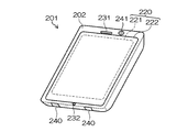
- FIG. 20 is an external view of a smartphone.
- FIG. 21 is a block diagram showing a configuration of the smartphone shown in FIG.
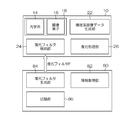
- FIG. 1 is a block diagram showing a system configuration example including a restoration filter generation device to which the present invention is applied and a digital camera which is an example of an image processing device.
- the digital camera 10 (image pickup apparatus) is based on an image pickup unit 18 having an optical system 14 and an image pickup device 16, and image data for each of a plurality of colors (R, G, B in this example) obtained by the image pickup unit 18.
- a luminance system image data generation unit 22 that generates luminance system image data that is image data relating to luminance, and a restoration filter F for performing restoration processing on the luminance system image data (or image data for each color) are stored.
- the restoration filter generation device 80 obtains an optical transfer function corresponding to the point image distribution in the optical system 14 of the digital camera 10 and variation information indicating variation in the optical transfer function (hereinafter also referred to as “OTF variation”).
- An acquisition unit 82 a restoration filter generation unit 84 that generates a restoration filter F based on information acquired by the information acquisition unit 82, and phase correction of luminance system image data (or color-specific image data) to the restoration filter F
- a switching unit 86 that switches whether or not to perform the switching.
- the “optical transfer function” acquired by the information acquisition unit 82 is obtained by, for example, PSF (Point Spread Function: hereinafter, also referred to as “point spread function” or “point spread function”) or Fourier transform of the PSF.
- PSF Point Spread Function: hereinafter, also referred to as “point spread function” or “point spread function”
- OTF Optical Transfer Function
- complex OTF is composed of MTF (Modulation Transfer Function: hereinafter referred to as “modulation transfer function” or “amplitude transfer function”) and PTF (Phase Transfer Function: hereinafter also referred to as “phase transfer function”).
- MTF Modulation Transfer Function
- modulation transfer function modulation transfer function
- amplitude transfer function amplitude transfer function
- phase transfer function Phase transfer function
- the “optical transfer function” may include at least one of a modulation component (hereinafter also referred to as “amplitude component”) and a phase component, and at least one of MTF and PTF may be calculated from the optical transfer function. That is, the “optical transfer function” indirectly includes information indicating at least one of MTF and PTF.
- variation information (also referred to as “OTF variation”) of the optical transfer function acquired by the information acquisition unit 82, for example, a color (a color space of a certain color system) that appears in luminance system image data (or image data for each color) OTF variation due to the upper color), individual variation due to the manufacture of the optical system 14, and OTF variation due to photographing conditions when photographing with the digital camera 10 (imaging device).
- the dispersion of the optical transfer function of the optical system due to the color is a dispersion between the optical transfer functions of the respective colors in the optical system.
- the information acquisition unit 82 of this example may acquire an optical transfer function for each color, and calculate the variation of the optical transfer function depending on the color based on the optical transfer function for each color.
- the restoration filter generation unit 84 generates a restoration filter that weakens the restoration strength according to the variation of the optical transfer function based on the information (optical transfer function and variation information) acquired by the information acquisition unit 82. Specifically, the restoration filter generation unit 84 makes the restoration strength of the restoration filter to be generated weaker than the restoration strength of the ideal filter determined on the assumption that there is no variation in the optical transfer function for each spatial frequency.
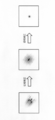
- FIG. 2 is an explanatory diagram for explaining the principle of the point image restoration process.
- FIG. 2 shows a case where a point image is captured as a subject image for easy understanding.
- the subject image is formed on the image pickup surface of the image pickup device 16 via the optical system 14 including the lens 11 and the diaphragm 12 and is picked up by the image pickup device 16.
- the image sensor 16 outputs deteriorated image data that is image data in which the subject image is deteriorated due to the aberration of the optical system 14. Therefore, the deterioration characteristics in the optical system 14 are obtained in advance as an optical transfer function corresponding to the photographing conditions (for example, aperture value, focal length, subject distance, lens type, etc.).
- the restoration processing unit 26 in FIG. 1 uses the restoration filter F to perform point image restoration processing (restoration processing) that cancels degradation of degraded image data. Then, it is possible to obtain restored image data whose degradation has been canceled.
- phase correction also referred to as “phase restoration”
- amplitude correction also referred to as “amplitude restoration”.
- Phase correction is image processing for restoring phase characteristics (PTF) deteriorated in the optical system.
- phase correction an asymmetric point spread shape can be corrected to a point symmetric point spread shape.
- Amplitude correction is image processing for restoring amplitude characteristics (MTF) deteriorated in the optical system.
- the point spread shape can be corrected to a point (delta function).
- the blur is severe or the S / N ratio is bad, it may not completely return to a point shape.
- the restoration processing unit 26 in FIG. 1 performs point image restoration processing on luminance system image data having a large visual effect.
- the restoration filter generation unit 84 in FIG. 1 generates a restoration filter F for luminance system image data.
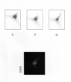
- FIG. 4 is an explanatory diagram for explaining that the optical transfer function varies depending on the color.
- the PSF shape of “white point” indicates the shape of point spread in a composite image obtained by combining R, G, B image data when a white point is imaged.
- the PSF shapes of “R”, “G”, and “B” in the figure indicate the shape of point spread in the R, G, and B image data, respectively.
- the white color of the PSF shape of “white point” has a higher light intensity
- the PSF shapes of “R”, “G”, and “B” have a higher light intensity. As shown in FIG.
- PSF shapes vary stochastically”. That is, the variation in the optical transfer function due to color is treated as a probability distribution.
- FIG. 5 is an explanatory diagram for explaining that the OTF variation depending on the color and the OTF variation due to manufacturing are handled using the same probability theory.
- “lens # 1” and “lens # 2” represent different individual optical systems 14 manufactured with the same design specifications.
- "Lens # 1” and “Lens # 2” have different R (red) PSF shapes, G (green) PSF shapes, and B (blue) PSF shapes.
- the PSF shape varies not only depending on the color, but also varies (individual variation) depending on the manufacturing of the optical system 14.
- the PSF shape variation due to color and the PSF shape variation due to manufacturing can be handled using the same probability theory.
- the probability distribution P y It is defined as (h y
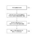
- FIG. 6 is a flowchart showing an outline of an example of restoration filter generation processing by the restoration filter generation unit 84.
- step S1 the information acquisition unit 82 acquires the optical transfer function in the optical system 14 for each of a plurality of colors (for example, three colors of R, G, and B).
- step S2 the information acquisition unit 82 calculates the average and dispersion of the optical transfer function in the normal distribution for each spatial frequency ( ⁇ x , ⁇ y ) based on the optical transfer function for each color acquired in step S1.
- the dispersion of the optical transfer function follows a normal distribution in a color space of a certain color system, and the average ⁇ ( ⁇ x , ⁇ y ) of the optical transfer function in the normal distribution and the parameter for calculating the restoration strength are The variance ⁇ 2 ( ⁇ x , ⁇ y ) is calculated.
- the variance ⁇ 2 ( ⁇ x , ⁇ y ) is “variation information” acquired (calculated) by the information acquisition unit 82, and the average ⁇ ( ⁇ x , ⁇ y ) is the center of variation in the optical transfer function. It can be said that it is representative of the optical transfer function shown.
- step S3 the restoration filter generator 84 calculates the restoration strength of the restoration filter based on the average ⁇ ( ⁇ x , ⁇ y ) and the variance ⁇ 2 ( ⁇ x , ⁇ y ) calculated in step S2.
- step S4 the restoration filter generation unit 84 generates a restoration filter having the restoration strength calculated in step S3.
- the present invention is not limited to the case of generating a restoration filter having both a phase correction function and an amplitude correction function, and a restoration filter having at least one of a phase correction function and an amplitude correction function may be generated. .
- FIG. 7 is a block diagram showing an outline of an example of the point image restoration process.
- the point image restoration process is a process for creating restored image data from the degraded image data using the restoration filter F.
- the point image restoration process is performed using a restoration filter in the real space constituted by, for example, N ⁇ M (N and M are integers of 2 or more) taps.
- N and M are integers of 2 or more) taps.
- the pixel data (restored image data) after the point image restoration processing is performed by performing a convolution operation on the filter coefficient assigned to each tap and the corresponding image data (the processing target pixel data of the degraded image data and the adjacent pixel data). Can be calculated.
- this convolution operation using the restoration filter F can be performed.
- a restoration filter in the real space constituted by N ⁇ M taps can be derived by performing an inverse Fourier transform on the restoration filter in the frequency space (also referred to as “spatial frequency domain”). Therefore, the restoration filter in the real space can be calculated as appropriate by specifying the restoration filter in the basic frequency space and specifying the number of taps of the restoration filter in the real space.
- FIG. 8 is a flowchart showing an outline of the switching process of whether or not to perform phase correction by the switching unit 86 of the restoration filter generation device 80 of FIG.
- the switching unit 86 determines whether or not to cause the restoration filter F to perform phase correction (phase restoration) in the point image restoration processing on the luminance system image data (step S11).
- the restoration filter generation unit 84 is a restoration filter having a function of performing phase correction in point image restoration processing on luminance system image data, A restoration filter with reduced overcorrection of the phase of the luminance system image data is generated (step S12).
- the restoration filter generation unit 84 obtains a plurality of transfer function information (PSF or MTF) for each color of a plurality of colors (R, G, B). Based on the transfer function information (PSF or MTF) mixed between the colors, the point image restoration process is performed to change only the amplitude component without changing the phase component with respect to the luminance system image data. Generate a restoration filter. That is, the restoration filter generation unit 84 generates a restoration filter having a function of performing only amplitude correction without performing phase correction in the point image restoration processing for luminance system image data.
- the amplitude correction is not performed for each color of a plurality of colors (R, G, B). Therefore, any one or a plurality of colors (R, G, B) is selected. Colors may be undercorrected (MTF is below 1.0) or overcorrected (MTF is above 1.0).
- the restoration filter generation unit 84 mixes transfer function information (PSF or MTF) between a plurality of colors (R, G, B), and based on the mixed transfer function information (PSF or MTF), a modulation transfer function
- PSF or MTF transfer function information
- a restoration filter that performs amplitude correction that brings the MTF close to “1” on average it is possible to generate a good restoration filter that suppresses undercorrection and overcorrection.
- the optical transfer function acquired by the information acquisition unit 82 is a complex OTF composed of MTF and PTF, and the variation information of the optical transfer function acquired by the information acquisition unit 82 indicates the variation of the complex OTF.
- the restoration filter generation processing will be specifically described by dividing it into embodiments.
- “optical transfer function variation information” is simply referred to as “OTF variation”.
- the restoration filter having the restoration strength corresponding to the OTF variation by color is generated, so that the restoration filter having high toughness is obtained. Generate.
- FIG. 9 shows a restoration processing model for explaining the restoration filter generation processing in the first embodiment.
- the restoration processing model shown in FIG. 9 is merely an example, and may be applied to other restoration processing models.
- the conversion M is a mapping from the RGB color space to the luminance system space (YCbCr color space).
- This conversion M depends only on the definition of the signal processing system in the image processing apparatus, “how to apply the restoration filter to the processed signal”. In general, since conversion from RGB space to luminance system space includes gamma correction, non-linear conversion is required. However, depending on the implementation form of luminance system restoration processing, linear conversion may be performed.
- FIG. 10 is a flowchart showing a flow of a restoration filter generation processing example in the first embodiment.
- the information acquisition unit 82 acquires the probability distribution P COLOR (Y ′, Cb, Cr) of Y ′, Cb, Cr (step S21).
- Y ′ is the value of the luminance signal (input pixel value) input to the restoration filter F in FIG.
- P COLOR (Y ′, Cb, Cr) is a color probability distribution in the luminance system image data obtained by the digital camera 10.
- P COLOR (Y ′, Cb, Cr) is an input color variation in a color space of a certain color system.
- the information acquisition unit 82 converts P COLOR (Y ′, Cb, Cr) into red (R), green (G), and blue (B) complex OTFs (OTF R , OTF G , OTF B). ) Is acquired (step S22).
- the information acquisition unit 82 uses the simultaneous distribution P RGB (h R , h G , h B
- ⁇ x , ⁇ y ) indicates that the random variables of R , G, and B have complex OTF random variables h R , h G, and h B. Is shown for each spatial frequency ( ⁇ x , ⁇ y ).
- ⁇ x , ⁇ y ) is calculated as follows:
- ⁇ () is the Kronecker delta function.
- OTF R ( ⁇ x , ⁇ y ), OTF G ( ⁇ x , ⁇ y ), and OTF B ( ⁇ x , ⁇ y ) are complex OTFs as uniquely determined design values.
- h R , h G , and h B are random variables of the complex OTF when there is input color variation.
- I R , I G , and I B are defined as in the following equations.
- the information acquisition unit 82 calculates the mean ⁇ and variance ⁇ 2 of the complex OTF in the population of complex OTFs in a specific color system for each spatial frequency ( ⁇ x , ⁇ y ) (step S24).
- the population is a set of complex OTFs that are within a range of color variation predetermined at the time of design.
- the average ⁇ ( ⁇ x , ⁇ y ) and variance ⁇ 2 ( ⁇ x , ⁇ y ), which are parameters in the above equation, are calculated by the information acquisition unit 82 by maximum likelihood estimation as in the following equation.
- the restoration filter generation unit 84 calculates the restoration strength of the restoration filter based on the average ⁇ ( ⁇ x , ⁇ y ) and the variance ⁇ 2 ( ⁇ x , ⁇ y ) (step S25).
- a luminance OTF (an OTF of a luminance signal) reflecting OTF variation in a population in a specific color system is expressed as the following equation.
- ⁇ ( ⁇ x , ⁇ y ) represents a random variable that follows a complex normal distribution with mean 0 and variance ⁇ 2 ( ⁇ x , ⁇ y ).
- the error criterion in the Wiener filter used for deconvolution in point image restoration processing is the square error between the original image (image before degradation by the optical system) and the restored image, and the average (or integration) of the input image (degraded image) and noise. It is defined as the one that took Since the optical transfer function is defined as a fixed value in the error criterion of such a known Wiener filter, if a known derivation formula is used as it is, overcorrection caused by OTF variation due to color or luminance system correction is avoided. Therefore, the color toughness is not exhibited.
- an error criterion for deriving a Wiener filter that also applies OTF variation due to color is used instead of using a known Wiener filter derivation formula as it is. Is introduced.
- the frequency characteristic of the restoration filter is f ( ⁇ x , ⁇ y )
- an error criterion J [f] obtained by averaging the signal, noise, and OTF variation is expressed as follows.
- S Y ( ⁇ x , ⁇ y ) and N Y ( ⁇ x , ⁇ y ) are the signal power and noise power of luminance Y, respectively.
- the frequency characteristic f of the Wiener filter to be obtained minimizes J in the above equation.
- Equation 8 the complex frequency characteristic f ( ⁇ x , ⁇ y ) of the Wiener filter to be obtained is as follows: .
- the complex frequency characteristic f ( ⁇ x , ⁇ y ) indicates the restoration strength of the restoration filter.
- the restoration strength is weakened (the denominator on the right side of the above equation is increased) to reduce the variation due to the color.
- a restoration filter having toughness characteristics can be generated.
- the restoration filter generation unit 84 of this example weakens the restoration strength as the spatial frequency has a larger OTF variation due to color.
- the restoration filter generation unit 84 generates a restoration filter having the restoration strength calculated in step S25 (step S26).
- the restoration filter is approximated to the complex frequency characteristic of the actual restoration filter within a given number of taps.
- the filter coefficient of is calculated.
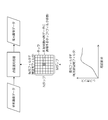
- FIG. 11 shows the average ⁇ ( ⁇ ), ⁇ ( ⁇ ) + ⁇ ( ⁇ ), ⁇ ( ⁇ ) ⁇ ( ⁇ ) in the normal distribution for only the real part (MTF) of the complex OTF for easy understanding.
- the restoration strength of the restoration filter is calculated based on the average ⁇ ( ⁇ ) without considering the OTF variation, there is a possibility that overcorrection occurs at a spatial frequency where ⁇ is large. Therefore, in the present invention, the restoration strength of the restoration filter is calculated so that it becomes ⁇ ( ⁇ ) + ⁇ ( ⁇ ) (or closer to ⁇ ( ⁇ ) + ⁇ ( ⁇ )) at a spatial frequency where ⁇ is large.
- the restoration filter is generated by calculating the filter coefficient of the restoration filter by discarding the phase characteristic from the obtained frequency characteristics of the restoration filter and approximating only the amplitude characteristic.
- Second Embodiment Factors of OTF variation to be considered in the restoration filter generation process include, in addition to the color considered in the first embodiment, manufacturing variations of the optical system 14 and variations in shooting conditions at the time of shooting in the imaging apparatus (for example, subject distance Measurement error).
- manufacturing variations of the optical system 14 and variations in shooting conditions at the time of shooting in the imaging apparatus (for example, subject distance Measurement error).
- subject distance Measurement error for example, subject distance Measurement error
- OTF variation due to manufacturing and OTF variation due to photographing conditions are phenomena that occur not only in luminance system image data but also in image data for each color. Therefore, in the following, a case where a restoration filter for point image restoration for R, G, and B color image data is generated will be described as an example.
- the information acquisition unit 82 acquires the simultaneous distribution P OTF (h R , h G , h B
- ⁇ x , ⁇ y ) is unique information obtained by analyzing the mechanism of occurrence of variation in manufacturing the optical system 14 and measuring a mass-produced sample.
- the OTF variation is the simultaneous distribution P OTF (h R , h G , h B
- ⁇ x , ⁇ y ) is constructed (calculated) in advance.
- P OTF (h R , h G , h B
- PSF imaging position variation the average of the OTF in the OTF variation
- PSF imaging position variation the average of the OTF in the OTF variation
- the information acquisition unit 82 calculates the average ⁇ and variance ⁇ 2 of the OTF in the normal distribution for each spatial frequency ( ⁇ x , ⁇ y ).
- the OTF variation for each spatial frequency ⁇ x , ⁇ y of the R, G, B image data (color-specific image data) input to the restoration filter F is expressed as a complex normal distribution (Circular symmetric complex normal distribution).
- the signal processing system can be corrected for each of R, G, and B colors, OTF variation is also obtained for each color.
- the index K indicating the color is K ⁇ ⁇ R, G, B ⁇
- the simultaneous distribution P K indicating the OTF variation for each color is expressed by the following equation.
- the average ⁇ K ( ⁇ x , ⁇ y ) and the variance ⁇ K 2 ( ⁇ x , ⁇ y ), which are parameters in the above equation, are obtained by maximum likelihood estimation as in the following equation.
- the frequency characteristic of the restoration filter is obtained in the same manner as in the first embodiment, and the restoration filter having the restoration strength corresponding to the frequency characteristic is generated.
- the optical transfer function is different from that assumed due to optical system manufacturing variation (or imaging condition variation). Artifacts caused by the problem can be accurately suppressed. Further, individual difference information for each optical system 14 is not required, and a restoration filter can be generated only from probabilistic statistical information of OTF variation.
- the manufacturing variation of the optical system is taken as an example, but the variation in photographing conditions such as the subject distance can be discussed in the same manner as in the present embodiment. That is, it is only necessary to generate a restoration filter having a restoration strength corresponding to variations in photographing conditions.
- the information acquisition unit 82 uses P COLOR (Y ′, Cb, Cr) defined in the first embodiment and P OTF (h R , h G , h B
- P COLOR (Y ′, Cb, Cr) is a probability distribution indicating color variation in the luminance system image data.
- ⁇ x , ⁇ y ) is a simultaneous distribution indicating the OTF variation of the optical system 14 due to manufacturing.
- the information acquisition unit 82 mixes both P COLOR (Y ′, Cb, Cr) and P OTF (h R , h G , h B
- ⁇ x , ⁇ y ) for each of R, G, and B colors is calculated (obtained) (step S42).
- ⁇ x , ⁇ y ) is a simultaneous distribution showing OTF variation for each color of R, G, B.
- I R , I G , and I B are defined as the following formula.
- the OTF is the same as in the first embodiment.
- the variance ⁇ 2 (or standard deviation ⁇ ) is calculated assuming that the variation is normally distributed, and then the frequency characteristic of the restoration filter F is calculated using the variance ⁇ 2 (or standard deviation ⁇ ) as a parameter.
- a restoration filter F having the frequency characteristics of the restored restoration filter F is generated.
- artifacts caused by the difference between the optical transfer function assumed by the input color can be accurately suppressed, and the optical system Artifacts caused by the difference in optical transfer function (PSF shape) from that assumed due to manufacturing variations can be accurately suppressed.
- individual difference information for each optical system 14 is not required, and a restoration filter can be generated only from probabilistic statistical information of the variation amount of OTF.
- FIG. 12 is a block diagram illustrating a hardware configuration example of the digital camera 10.
- the CPU 33 sequentially executes various programs and data read from the memory 34 based on an instruction input to the operation unit 9, and comprehensively controls each unit of the digital camera 10.
- the memory 34 corresponding to the restoration filter storage unit 24 in FIG. 1 stores the restoration filter F in addition to the various programs described above.
- the memory 34 functions as a work memory for the CPU 33 to execute processing and a temporary storage destination for various data.
- a single-plate color image sensor 16 is disposed behind the optical system 14.
- a plurality of pixels arranged in a matrix with a predetermined pattern arrangement (Bayer arrangement, G stripe R / G complete checkerboard, X-Trans arrangement, honeycomb arrangement, etc.) are formed on the imaging surface of the imaging element 16.
- Each pixel includes a microlens, a color filter (in this example, a color filter of R (red), G (green), and B (blue)) and a photodiode.
- the imaging element 16 constitutes an imaging apparatus (imaging means) according to the present invention together with the optical system 14, and converts the subject image formed on the imaging surface by the optical system 14 into an electrical output signal and outputs the electrical output signal. .
- the imaging device 16 various types of imaging devices such as a CCD (Charge-Coupled Device) color imaging device and a CMOS (Complementary Metal-Oxide Semiconductor) color imaging device are used.
- the image sensor driver 45 controls driving of the image sensor 16 under the control of the CPU 33.
- the signal adjustment circuit 48 performs various signal adjustment processes on the output signal output from the image sensor 16 to generate RGB mosaic image data R1, G1, B1 associated with the color filter array of the image sensor 16.
- the signal adjustment circuit 48 is configured by, for example, a CDS / AGC circuit or an A / D conversion circuit when the imaging device 16 is a CCD type, and is configured by, for example, an amplifier when the image sensor 16 is a CMOS type.
- the image processing circuit 49 constitutes the image processing apparatus of the present invention.
- the image processing circuit 49 performs black level adjustment processing, white balance correction processing, gamma correction processing, demosaicing processing, YC conversion on the mosaic image data of each of a plurality of colors R, G, and B input from the signal adjustment circuit 48.
- Luminance system image data Y and color difference system image data Cb, Cr are generated by performing processing, point image restoration processing, and the like.
- Luminance system image data Y and color difference system image data Cb, Cr are temporarily stored in a VRAM area of the memory 34 (VRAM may be provided separately).
- the VRAM area has a memory area for live view images that stores two consecutive field images.
- the luminance system image data Y and the color difference system image data Cb, Cr stored in the VRAM area are sequentially output to the display unit 8. Thereby, a live view image is displayed on the display unit 8.
- the compression / decompression processing circuit 51 performs compression processing on the luminance system image data Y and the color difference system image data Cb, Cr stored in the VRAM area when the shutter button of the operation unit 9 is pressed during the photographing mode. .
- the compression / decompression processing circuit 51 performs decompression processing on the compressed image data obtained from the memory card 30 via the media I / F 52.
- the media I / F 52 performs recording and reading of compressed image data with respect to the memory card 30.
- the image processing circuit 49 mainly includes an input unit 49a, a demosaic processing unit 49b, a conversion unit 49c (corresponding to the luminance system image data generation unit 22 in FIG. 1), and a restoration processing unit 49d (26 in FIG. 1). )have.
- the image processing circuit 49 also includes a correction processing unit that performs white balance correction processing, gamma correction processing, and the like, but illustration and description of these correction processing units are omitted in order to prevent the description from becoming complicated. To do.
- the input unit 49a outputs the RGB mosaic image data R1, G1, B1 input from the signal adjustment circuit 48 to the demosaic processing unit 49b. That is, the input unit 49a functions as an input I / F to which image data of each color obtained by imaging with the image sensor 16 is input.
- the demosaic processing unit 49b performs demosaic processing (also referred to as synchronization processing) that calculates (converts into simultaneous equations) all the RGB color information for each pixel based on the mosaic image data R1, G1, and B1 of each color, RGB image data R2, G2, and B2 composed of color data of three RGB planes are generated.
- the demosaic processing unit 49b outputs the RGB image data R2, G2, and B2 to the conversion unit 49c.
- the conversion unit 49c (luminance system image data generation unit 22) performs YC conversion processing on the RGB image data R2, G2, and B2 to generate luminance system image data Y and color difference system image data Cb and Cr.
- the luminance system image data Y is described by taking the value of the luminance signal in the color space represented by “Y, Cb, Cr” as an example, but it is data that contributes to the luminance of the image. If there is no particular limitation, it means various data having information on the brightness of the captured image. For example, data having the highest contribution rate for obtaining a luminance signal, data corresponding to a color filter of a color that contributes most to luminance, and the like can be given.
- the restoration processing unit 49d (26 in FIG. 1) reads the restoration filter F stored in the memory 34 and performs restoration processing on the luminance system image data Y using the restoration filter F. This restoration processing is performed only on the luminance system image data Y that has a large visual effect in order to reduce the processing load. By performing the point image restoration process, image deterioration (such as blur) due to the aberration of the optical system 14 is corrected.
- the point image (optical image) transmitted through the optical system 14 is formed on the imaging surface of the image sensor 16 as a large point image (blurred image) as shown as “degraded image data” in FIG.
- a small point image (high resolution image) is restored as shown in FIG.
- FIG. 14 is a block diagram illustrating a hardware configuration example of a computer device 180 used as the restoration filter generation device 80.
- the CPU 181 controls each part of the computer device 180.
- the storage unit 182 stores a restoration filter generation processing program, an optical transfer function, and optical transfer function variation information.
- various non-temporary recording media such as a hard disk drive, a compact disk, various magneto-optical recording media such as a DVD, and a semiconductor memory such as SSD (Solid State Drive) are used in addition to a ROM and an EEPROM. be able to.
- the communication unit 183 communicates with a server device (not shown) via a network, and acquires an optical transfer function and optical transfer function variation information from the server device via the network.
- the operation unit 184 receives an instruction input from the operator.
- the display unit 185 displays various information.
- the information acquisition unit 82 of FIG. 1 may be configured by the CPU 181.
- the CPU 181 calculates variation information of the optical transfer function from the optical transfer function.
- the CPU 181 (or the operation unit 184) constitutes the switching unit 86 in FIG.
- the CPU 181 constitutes the restoration filter generation unit 84 of FIG.
- the digital camera 10 may include a restoration filter generation device and an image processing device.
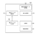
- the digital camera 10 in FIG. 15 includes an information acquisition unit 82, a restoration filter generation unit 84, and a switching unit 86 that configure the restoration filter generation device 80 in FIG.
- the computer device 180 may include a restoration filter generation device and an image processing device.
- a computer apparatus 180 in FIG. 16 includes a restoration filter storage unit 24 and a restoration processing unit 26 that configure the digital camera 10 in FIG. 1, and a luminance system image data acquisition unit 92 that acquires luminance system image data.
- the luminance system image data acquisition unit 92 is configured by, for example, the communication unit 183 in FIG.
- the system configuration is not limited to the case described in FIGS. 1, 15, and 16, and other configurations may be used.
- the restoration filter generation unit 84 and the restoration processing unit 26 may be provided in another device such as a server device.
- the server device includes the restoration processing unit 26, for example, image data is transmitted from the digital camera 10 or the computer device 180 to the server device, and the restoration processing unit 26 of the server device performs restoration processing on the image data.
- the image data after restoration processing (restored image data) may be transmitted / provided to the transmission source of the image data before restoration processing.
- the aspect to which the present invention can be applied is not limited to a digital camera, a computer device, and a server device.
- the cameras whose main function is imaging functions other than imaging (call function) , Communication functions, and other computer functions).
- Other modes to which the present invention can be applied include, for example, a mobile phone having a camera function, a smartphone, a PDA (Personal Digital Assistants), and a portable game machine.
- a smartphone to which the present invention can be applied will be described later.
- the point image restoration process (restoration process) in the above-described embodiment is based on the specific imaging conditions (for example, aperture value, F value, focal length, lens type, etc.), and image degradation due to aberration of the optical system.
- the restoration process to which the present invention can be applied is not limited to the restoration process in the above-described embodiment.
- the present invention can be applied to a restoration process for image data captured and acquired by an optical system (lens, aperture, etc.) having an enlarged depth of field (EDoF) (EDoF: Extended Depth of Field (Focus)). It is possible to apply the restoration processing according to the invention.
- High-resolution image data in a wide range of focus by performing restoration processing on image data of a blurred image captured and acquired with the depth of field (depth of focus) expanded by the EDoF optical system Can be restored.
- it is a restoration filter based on transfer function information (PSF, OTF, MTF, PTF, etc.) of the EDoF optical system, and good image restoration is possible within the range of the expanded depth of field (depth of focus).
- a restoration process using a restoration filter having a filter coefficient set so as to be performed is performed.
- FIG. 17 is a block diagram illustrating an embodiment of the imaging module 101 including the EDoF optical system.
- the imaging module (digital camera or the like) 101 of this example includes an EDoF optical system 110 (optical system), an imaging element 112, an AD conversion unit 114, and an image processing unit 120 (restoration processing block).
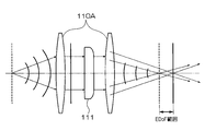
- FIG. 18 is a diagram illustrating an example of the EDoF optical system 110.
- the EDoF optical system 110 of this example includes a photographic lens 110A having a fixed focal point and an optical filter 111 disposed at the pupil position.
- the optical filter 111 modulates the phase and converts the EDoF optical system 110 (the optical system 14 in FIG. 1) to EDoF so that an expanded depth of field (depth of focus) (EDoF) is obtained.
- the photographing lens 110A and the optical filter 111 constitute a lens unit that modulates the phase and expands the depth of field.
- the EDoF optical system 110 includes other components as necessary.
- a diaphragm (not shown) is disposed in the vicinity of the optical filter 111.
- the optical filter 111 may be one sheet or a combination of a plurality of sheets.
- the optical filter 111 is merely an example of an optical phase modulation unit, and the EDoF conversion of the EDoF optical system 110 (the photographing lens 110A) may be realized by other units.
- the EDoF optical system 110 may be realized as EDoF by using the photographing lens 110A designed to have the same function as that of the optical filter 111 of the present example.
- a modulation element may be employed.
- the EDoF conversion of the EDoF optical system 110 can be realized by various means for changing the wavefront of the image formed on the light receiving surface of the image sensor 112.
- optical element whose thickness changes “optical element whose refractive index changes (refractive index distributed wavefront modulation lens, etc.)”, “optical element whose thickness and refractive index change due to coding on the lens surface (wavefront) "Modulation hybrid lens, optical element formed as a phase plane on the lens surface, etc.)” and “liquid crystal element capable of modulating light phase distribution (liquid crystal spatial phase modulation element, etc.)” into EDoF optical system 110 of EDoF It can be adopted as a means.
- the present invention can also be applied to a case that can be formed by the photographic lens 110A itself without using a modulation element.
- the EDoF optical system 110 of this example can be reduced in size because it can omit a focus adjustment mechanism that performs mechanical focus adjustment, and can be suitably mounted on a mobile phone with a camera or a portable information terminal.
- the optical image after passing through the EDoF EDoF optical system 110 is formed on the image pickup surface of the image pickup device 112 shown in FIG. 17, and is converted into an electric signal here.
- the image sensor 112 has basically the same configuration as the image sensor (16 in FIGS. 1, 12, and 15) of each of the above embodiments.
- the image sensor 112 converts subject light imaged on the imaging surface by the EDoF optical system 110 into a signal corresponding to the amount of incident light, and outputs an analog RGB image signal.
- the AD conversion unit 114 changes the analog RGB image signal output from the image sensor 112 into mosaic image data of digital R, G, and B colors.
- the mosaic image data for each color is input to the image processing unit 120.
- the image processing unit 120 includes, for example, a black level adjustment unit 122, a white balance gain unit 123, a gamma processing unit 124, a demosaic processing unit 125, an RGB / YCrCb conversion unit 126, and a Y signal restoration processing unit 127 (restoration). Processing unit).
- the black level adjustment unit 122 performs black level adjustment on the mosaic image data of each color output from the AD conversion unit 114.
- a known method can be adopted for black level adjustment. For example, when attention is paid to a certain effective photoelectric conversion element, an average of dark current amount acquisition signals corresponding to each of a plurality of OB photoelectric conversion elements included in the photoelectric conversion element row including the effective photoelectric conversion element is obtained, and the effective The black level is adjusted by subtracting the average from the dark current amount acquisition signal corresponding to the photoelectric conversion element.
- the white balance gain unit 123 performs gain adjustment according to the white balance gain of each RGB color signal included in the mosaic image data in which the black level data is adjusted.
- the gamma processing unit 124 performs gamma correction that performs gradation correction such as halftone so that the mosaic image data of each color that has been subjected to white balance adjustment has preferable gamma characteristics.
- the demosaic processing unit 125 performs demosaic processing on the mosaic image data of each color after the gamma correction, and outputs RGB image data composed of color data of R, G, and B.
- the RGB / YCrCb conversion unit 126 is basically the same as the luminance system image data generation unit (22 in FIGS. 1 and 15) of the above-described embodiments, and outputs R, G, B output from the demosaic processing unit 125. YC conversion processing is performed on the color data of the three surfaces to generate and output luminance system image data Y and color difference system image data Cr and Cb.
- the Y signal restoration processing unit 127 performs restoration processing on the luminance system image data Y from the RGB / YCrCb conversion unit 126 based on a restoration filter stored in advance.
- a restoration filter corresponding to the optical filter 111 is stored in a memory (not shown). Further, the kernel size of the deconvolution kernel is not limited to 7 ⁇ 7.
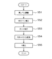
- restoration processing by the image processing unit 120 (restoration processing block) will be described using the flowchart shown in FIG.
- the mosaic image data of each color is input from the AD conversion unit 114 to one input of the black level adjustment unit 122, and black level data is input to the other input.
- the black level adjustment unit 122 subtracts the black level data from the mosaic image data of each color, and outputs the mosaic image data of each color after the subtraction process to the white balance gain unit 123 (step S51). Thereby, the black level component is not included in the mosaic image data of each color.
- the mosaic image data of each color after black level adjustment is sequentially processed by the white balance gain unit 123 and the gamma processing unit 124 (steps S52 and S53).
- the gamma-corrected mosaic image data of each color is demosaiced by the demosaic processing unit 125 and then converted into luminance system image data Y and color difference system image data Cr and Cb by the RGB / YCrCb conversion unit 126 (step S54). .
- the Y signal restoration processing unit 127 performs a restoration process in which the luminance signal Y is subjected to a deconvolution process corresponding to the phase modulation of the optical filter 111 of the EDoF optical system 110 (step S55).
- the Y signal restoration processing unit 127 stores a luminance signal (in this case, a luminance signal of 7 ⁇ 7 pixels) corresponding to a predetermined unit pixel group centered on an arbitrary pixel to be processed, and is stored in a memory or the like in advance.
- Deconvolution processing (deconvolution calculation processing) is performed on the restoration filter (7 ⁇ 7 convolution kernel and its calculation coefficient).
- the Y signal restoration processing unit 127 performs restoration processing for removing image blur of the entire image by repeating the deconvolution processing for each pixel group of a predetermined unit so as to cover the entire area of the imaging surface.
- the restoration filter is determined according to the position of the center of the pixel group to be subjected to the deconvolution process. That is, a common restoration filter is applied to adjacent pixel groups. Further, in order to simplify the restoration process, it is preferable to apply a common restoration filter to all the pixel groups.
- the point image (optical image) of the luminance signal after passing through the EDoF optical system 110 is imaged on the image sensor 112 as a large point image (blurred image), but by the deconvolution processing in the Y signal restoration processing unit 127. , Restored to a small point image (high resolution image).
- the restoration process As described above, by applying the restoration process to the luminance system image data after the demosaic process, it is not necessary to have the parameters of the restoration process separately for RGB, and the restoration process can be speeded up. Further, R, G, and B image signals corresponding to the R, G, and B pixels at the skipped positions are not collectively deconvoluted into one unit, but the luminance signals of adjacent pixels are processed in a predetermined unit. In summary, since the deconvolution process is performed by applying a common restoration filter to the unit, the accuracy of the restoration process is improved. Note that the color difference image data Cr and Cb are acceptable in terms of image quality even if the resolution is not increased in the restoration process due to the visual characteristics of the human eye.
- the color-difference image data Cr and Cb are compressed at a higher compression rate than the luminance image data Y, so that it is not necessary to increase the resolution in the restoration process.
- JPEG a compression format
- the color-difference image data Cr and Cb are compressed at a higher compression rate than the luminance image data Y, so that it is not necessary to increase the resolution in the restoration process.
- the point image restoration processing according to each embodiment of the present invention can also be applied to the restoration processing of the EDoF system as described above.
- the restoration filter generation device according to each of the above embodiments is set so that satisfactory image restoration is possible within the range of the expanded depth of field (depth of focus) based on the transfer function information of the EDoF optical system.
- a restoration filter having the filtered filter coefficients is generated.
- a digital camera and a computer apparatus have been described as examples of the image processing apparatus and the imaging apparatus of the present invention.
- a mobile phone or a smartphone having a photographing function a PDA (Personal Digital Assistants), a tablet
- the present invention can also be applied to terminals and portable game machines.
- a smartphone will be described as an example, and will be described in detail with reference to the drawings.
- FIG. 20 shows an appearance of a smartphone 201 which is an embodiment of the photographing apparatus of the present invention.
- a smartphone 201 illustrated in FIG. 20 includes a flat housing 202, and a display input in which a display panel 221 serving as a display unit and an operation panel 222 serving as an input unit are integrated on one surface of the housing 202. Part 220 is provided.
- the housing 202 includes a speaker 231, a microphone 232, an operation unit 240, and a camera unit 241. Note that the configuration of the housing 202 is not limited to this, and, for example, a configuration in which the display unit and the input unit are independent, or a configuration having a folding structure or a slide mechanism may be employed.
- FIG. 21 is a block diagram showing a configuration of the smartphone 201 shown in FIG.
- the main components of the smartphone include a wireless communication unit 210, a display input unit 220, a call unit 230, an operation unit 240, a camera unit 241, a storage unit 250, and an external input / output unit. 260, a GPS (Global Positioning System) receiving unit 270, a motion sensor unit 280, a power supply unit 290, and a main control unit 200.
- a wireless communication function for performing mobile wireless communication via the base station device BS and the mobile communication network NW is provided as a main function of the smartphone 201.
- the wireless communication unit 210 performs wireless communication with the base station apparatus BS accommodated in the mobile communication network NW according to an instruction from the main control unit 200. Using such wireless communication, transmission / reception of various file data such as audio data and image data, e-mail data, and reception of Web data, streaming data, and the like are performed.
- the display input unit 220 displays images (still images and moving images), character information, and the like visually under the control of the main control unit 200, visually transmits information to the user, and detects a user operation on the displayed information.
- This is a so-called touch panel, and includes a display panel 221 and an operation panel 222.
- the display panel 221 uses an LCD (Liquid Crystal Display), an OELD (Organic Electro-Luminescence Display), or the like as a display device.
- the operation panel 222 is a device that is placed so that an image displayed on the display surface of the display panel 221 is visible and detects one or a plurality of coordinates operated by a user's finger or stylus. When such a device is operated with a user's finger or stylus, a detection signal generated due to the operation is output to the main control unit 200. Next, the main control unit 200 detects an operation position (coordinates) on the display panel 221 based on the received detection signal.
- the display panel 221 and the operation panel 222 of the smartphone 201 illustrated as an embodiment of the photographing apparatus of the present invention integrally constitute a display input unit 220, but the operation panel The arrangement 222 covers the display panel 221 completely.
- the operation panel 222 may have a function of detecting a user operation even in an area outside the display panel 221.
- the operation panel 222 includes a detection area (hereinafter referred to as a display area) for an overlapping portion that overlaps the display panel 221 and a detection area (hereinafter, a non-display area) for an outer edge portion that does not overlap the other display panel 221. May be included).
- the operation panel 222 may include two sensitive regions of the outer edge portion and the other inner portion. Further, the width of the outer edge portion is appropriately designed according to the size of the housing 202 and the like. Furthermore, examples of the position detection method employed in the operation panel 222 include a matrix switch method, a resistive film method, a surface acoustic wave method, an infrared method, an electromagnetic induction method, and a capacitance method. You can also
- the call unit 230 includes a speaker 231 and a microphone 232, converts user's voice input through the microphone 232 into voice data that can be processed by the main control unit 200, and outputs the voice data to the main control unit 200, or a wireless communication unit
- the audio data received by 210 or the external input / output unit 260 is decoded and output from the speaker 231.
- the speaker 231 can be mounted on the same surface as the display input unit 220 and the microphone 232 can be mounted on the side surface of the housing 202.
- the operation unit 240 is a hardware key using a key switch or the like, and receives an instruction from the user.
- the operation unit 240 is mounted on the side surface of the housing 202 of the smartphone 201 and is turned on when pressed with a finger or the like, and is turned off by a restoring force such as a spring when the finger is released. It is a push button type switch.
- the storage unit 250 includes a control program and control data of the main control unit 200, application software, address data that associates the name and telephone number of a communication partner, transmitted / received e-mail data, Web data downloaded by Web browsing, The downloaded content data is stored, and streaming data and the like are temporarily stored.
- the storage unit 250 includes an internal storage unit 251 built in the smartphone and an external storage unit 252 having a removable external memory slot.
- Each of the internal storage unit 251 and the external storage unit 252 constituting the storage unit 250 includes a flash memory type, a hard disk type, a multimedia card micro type, a multimedia card micro type, Realized using storage media (computer-readable non-transitory recording media) such as card-type memory (for example, MicroSD (registered trademark) memory), RAM (Random Access Memory), ROM (Read Only Memory), etc. .
- storage media computer-readable non-transitory recording media
- card-type memory for example, MicroSD (registered trademark) memory
- RAM Random Access Memory
- ROM Read Only Memory
- the external input / output unit 260 serves as an interface with all external devices connected to the smartphone 201, and communicates with other external devices (for example, universal serial bus (USB), IEEE 1394, etc.) or a network.
- external devices for example, universal serial bus (USB), IEEE 1394, etc.
- a network for example, Internet, wireless LAN, Bluetooth (registered trademark), RFID (Radio Frequency Identification), Infrared Data Association (IrDA) (registered trademark), UWB (Ultra Wideband) (registered trademark) ZigBee) (registered trademark, etc.) for direct or indirect connection.
- an external device connected to the smartphone 201 for example, a wired / wireless headset, a wired / wireless external charger, a wired / wireless data port, a memory card (Memory card) connected via a card socket, or a SIM (Subscriber).
- Identity Module Card / UIM (User Identity Module Card) card external audio / video equipment connected via audio / video I / O (Input / Output) terminal, external audio / video equipment connected wirelessly, yes / no
- the external input / output unit 260 transmits data received from such an external device to each component inside the smartphone 201, or allows the data inside the smartphone 201 to be transmitted to the external device. Can do.
- the GPS receiving unit 270 receives GPS signals transmitted from the GPS satellites ST1 to STn according to instructions from the main control unit 200, executes positioning calculation processing based on the received plurality of GPS signals, A position consisting of longitude and altitude is detected.
- the GPS receiving unit 270 can acquire position information from the wireless communication unit 210 or the external input / output unit 260 (for example, a wireless LAN), the GPS receiving unit 270 can also detect the position using the position information.
- the motion sensor unit 280 includes, for example, a three-axis acceleration sensor, and detects the physical movement of the smartphone 201 in accordance with an instruction from the main control unit 200. By detecting the physical movement of the smartphone 201, the moving direction and acceleration of the smartphone 201 are detected. Such a detection result is output to the main control unit 200.
- the power supply unit 290 supplies power stored in a battery (not shown) to each unit of the smartphone 201 in accordance with an instruction from the main control unit 200.
- the main control unit 200 includes a microprocessor, operates according to a control program and control data stored in the storage unit 250, and controls each unit of the smartphone 201 in an integrated manner.
- the main control unit 200 includes a mobile communication control function for controlling each unit of the communication system and an application processing function in order to perform voice communication and data communication through the wireless communication unit 210.
- the application processing function is realized by the main control unit 200 operating according to the application software stored in the storage unit 250.
- Application processing functions include, for example, an infrared communication function for controlling external input / output unit 260 to perform data communication with an opposite device, an e-mail function for sending and receiving e-mails, and a web browsing function for browsing web pages. .
- the main control unit 200 also has an image processing function such as displaying video on the display input unit 220 based on image data (still image or moving image data) such as received data or downloaded streaming data.
- the image processing function refers to a function in which the main control unit 200 decodes the image data, performs image processing on the decoding result, and displays an image on the display input unit 220.
- the main control unit 200 executes display control for the display panel 221 and operation detection control for detecting a user operation through the operation unit 240 and the operation panel 222.
- the main control unit 200 By executing the display control, the main control unit 200 displays an icon for starting application software, a software key such as a scroll bar, or a window for creating an e-mail.
- a software key such as a scroll bar, or a window for creating an e-mail.
- the scroll bar refers to a software key for accepting an instruction to move a display portion of an image such as a large image that cannot fit in the display area of the display panel 221.
- the main control unit 200 detects a user operation through the operation unit 240 or receives an operation on the icon or an input of a character string in the input field of the window through the operation panel 222. Or a display image scroll request through a scroll bar.
- the main control unit 200 causes the operation position with respect to the operation panel 222 to overlap with the display panel 221 (display area) or other outer edge part (non-display area) that does not overlap with the display panel 221.
- a touch panel control function for controlling the sensitive area of the operation panel 222 and the display position of the software key.
- the main control unit 200 can also detect a gesture operation on the operation panel 222 and execute a preset function according to the detected gesture operation.
- Gesture operation is not a conventional simple touch operation, but an operation that draws a trajectory with a finger or the like, designates a plurality of positions at the same time, or combines these to draw a trajectory for at least one of a plurality of positions. means.
- the camera unit 241 is a digital camera that performs electronic photography using an imaging element such as a CMOS (Complementary Metal Oxide Semiconductor) or a CCD (Charge-Coupled Device).
- the camera unit 241 converts image data obtained by imaging into compressed image data such as JPEG (Joint Photographic Coding Experts Group) under the control of the main control unit 200, and records the data in the storage unit 250 or externally.
- the data can be output through the input / output unit 260 and the wireless communication unit 210.
- the camera unit 241 is mounted on the same surface as the display input unit 220, but the mounting position of the camera unit 241 is not limited to this and may be mounted on the back surface of the display input unit 220. Alternatively, a plurality of camera units 241 may be mounted. In the case where a plurality of camera units 241 are mounted, the camera unit 241 used for shooting can be switched for shooting alone, or a plurality of camera units 241 can be used for shooting simultaneously.
- the camera unit 241 can be used for various functions of the smartphone 201.
- an image acquired by the camera unit 241 can be displayed on the display panel 221, or the image of the camera unit 241 can be used as one of operation inputs of the operation panel 222.
- the GPS receiving unit 270 detects the position, the position can also be detected with reference to an image from the camera unit 241.
- the optical axis direction of the camera unit 241 of the smartphone 201 can be determined without using the triaxial acceleration sensor or in combination with the triaxial acceleration sensor. It is also possible to determine the current usage environment.
- the image from the camera unit 241 can be used in the application software.
- the position information acquired by the GPS receiving unit 270 to the image data of the still image or the moving image, the voice information acquired by the microphone 232 (the text information may be converted into voice information by the main control unit or the like), Posture information and the like acquired by the motion sensor unit 280 can be added and recorded in the storage unit 250, or can be output through the external input / output unit 260 and the wireless communication unit 210.
- the above-described processing units related to the point image restoration process can be appropriately realized by the main control unit 200, the storage unit 250, and the like, for example.
- DESCRIPTION OF SYMBOLS 10 ... Digital camera, 14 ... Optical system, 16 ... Imaging device, 18 ... Imaging part, 22 ... Luminance system image data generation part, 24 ... Restoration filter storage part, 26 ... Restoration processing part, 80 ... Restoration filter production
Landscapes
- Engineering & Computer Science (AREA)
- Multimedia (AREA)
- Signal Processing (AREA)
- Physics & Mathematics (AREA)
- General Physics & Mathematics (AREA)
- Theoretical Computer Science (AREA)
- Image Processing (AREA)
- Studio Devices (AREA)
- Color Television Image Signal Generators (AREA)
Abstract
Description
図1は、本発明を適用した復元フィルタ生成装置と画像処理装置の一例であるデジタルカメラとを含むシステム構成例を示すブロック図である。
図2は、点像復元処理の原理を説明するための説明図である。図2では、理解を容易にするため、被写体像として点像を撮像した場合を示している。被写体像は、レンズ11及び絞り12を含む光学系14を介して、撮像素子16の撮像面に結像され、その撮像素子16により撮像される。その撮像素子16からは、光学系14の収差に起因して被写体像が劣化した画像データである劣化画像データが出力される。そこで、光学系14における劣化の特性を、撮影条件(例えば、絞り値、焦点距離、被写体距離、レンズ種類、など)に応じた光学伝達関数として、予め求めておく。また、図1の復元フィルタ生成部84によって、光学伝達関数及びばらつき情報に基づいて、点像復元処理用の復元フィルタFを生成する。図1の復元処理部26によって、復元フィルタFを用い、劣化画像データの劣化をキャンセルする点像復元処理(復元処理)を行う。そうすると、劣化がキャンセルされた復元画像データを得ることができる。
図4は、色に依存して光学伝達関数にばらつきが生じることを説明するための説明図である。尚、図中、「白色点」のPSF形状は、白色点を撮像した際にR,G,B画像データを合成した合成画像における点広がりの形状を示している。また、図中の「R」,「G」,「B」のPSF形状は、それぞれR,G,B画像データにおける点広がりの形状を示している。尚、図示の都合上、「白色点」のPSF形状では白いほど光の強度が大きく、「R」,「G」,「B」のPSF形状では黒いほど光の強度が大きい。図4に示すように、R(赤)のPSF形状と、G(緑)のPSF形状と、B(青)のPSF形状とで、ばらつきが生じる。このようなPSF形状のばらつきは、MTF(変調伝達関数)及びPTF(位相伝達関数)からなる複素OTFのばらつきに対応している。
図8は、図1の復元フィルタ生成装置80の切替部86による位相補正実施有無の切替処理の概略を示すフローチャートである。
第1実施形態では、輝度系画像データに対する点像復元処理用の復元フィルタの生成処理において、色によるOTFばらつきに応じた復元強度を有する復元フィルタを生成することにより、タフネス性の高い復元フィルタを生成する。









復元フィルタ生成処理で考慮すべきOTFばらつきの要因としては、第1実施形態において考慮した色のほかに、光学系14の製造ばらつきや、撮像装置における撮影時の撮影条件のばらつき(例えば被写体距離の測定誤差)が挙げられる。以下では、例として、光学系14の製造によるOTFばらつきを考慮した、タフネス性の高い復元フィルタ生成処理例を説明する。また、製造によるOTFばらつきや、撮影条件によるOTFばらつきは、輝度系画像データに限らず、色別の画像データでも、生じる現象である。そこで、以下では、R,G,Bの色別の画像データに対する点像復元用の復元フィルタを生成する場合を例として、説明する。


第3実施形態では、輝度系画像データに対する点像復元処理用の復元フィルタの生成処理において、色によるOTFばらつきだけでなく、光学系の製造によるOTFばらつきにも応じて、タフネス性の高い復元フィルタを生成する。尚、本実施形態では、光学系の製造ばらつきを例に挙げるが、被写体距離等の撮影条件のばらつきに関しても、本実施形態と同様に論じることができる。即ち、撮影条件のばらつきに応じた復元強度を有する復元フィルタを生成すればよい。


図12は、デジタルカメラ10のハードウェア構成例を示すブロック図である。
図14は、復元フィルタ生成装置80として用いられるコンピュータ装置180のハードウェア構成例を示すブロック図である。
前述の実施形態では、図1に示すように復元フィルタ生成装置80と、画像処理装置としてのデジタルカメラ10とが個別に構成される場合を例に説明したが、本発明はこのような場合に限定されない。
上述の実施形態における点像復元処理(復元処理)は、特定の撮影条件(例えば、絞り値、F値、焦点距離、レンズ種類、など)に応じて、光学系の収差に因る画像の劣化を補正することで本来の被写体像を復元する画像処理であるが、本発明を適用可能な復元処理は上述の実施形態における復元処理に限定されるものではない。例えば、拡大された被写界(焦点)深度(EDoF:Extended Depth of Field(Focus))を有する光学系(レンズ、絞り、等)によって撮影取得された画像データに対する復元処理に対しても、本発明に係る復元処理を適用することが可能である。EDoF光学系によって被写界深度(焦点深度)が拡大された状態で撮影取得されるボケ画像の画像データに対して復元処理を行うことで、広範囲でピントが合った状態の高解像度の画像データを復元生成することができる。この場合、EDoF光学系の伝達関数情報(PSF、OTF、MTF、PTF、等)に基づく復元フィルタであって、拡大された被写界深度(焦点深度)の範囲内において良好な画像復元が可能となるよう設定されたフィルタ係数を有する復元フィルタを用いた復元処理が行われる。
上記各実施形態では本発明の画像処理装置及び撮像装置としてデジタルカメラ、コンピュータ装置を例に挙げて説明を行ったが、例えば、撮影機能を有する携帯電話機やスマートフォン、PDA(Personal Digital Assistants)、タブレット端末、携帯型ゲーム機にも本発明を適用することができる。以下、スマートフォンを例に挙げ、図面を参照しつつ、詳細に説明する。
Claims (30)
- 光学系を有する撮像装置で得られる色別の画像データに基づいて生成された、輝度に関する画像データである輝度系画像データに対して復元処理を行うための復元フィルタを生成する復元フィルタ生成装置であって、
前記光学系の光学伝達関数の色に依存するばらつきを示すばらつき情報を取得する情報取得部と、
前記復元フィルタを生成する復元フィルタ生成部と、を備え、
前記復元フィルタ生成部は、前記情報取得部によって取得された前記ばらつき情報に基づいて、前記色に依存するばらつきに応じて復元強度を弱くする復元フィルタであって、前記色に依存するばらつきが無いと仮定して決められた理想フィルタの復元強度よりも復元強度を弱くする復元フィルタを生成する、復元フィルタ生成装置。 - 前記ばらつき情報は、前記色に依存するばらつきが正規分布に従うとして算出された前記光学伝達関数の分散である、請求項1に記載の復元フィルタ生成装置。
- 前記情報取得部は、色別の光学伝達関数を取得し、前記色別の光学伝達関数に基づいて前記色に依存するばらつきを算出する、請求項1又は2に記載の復元フィルタ生成装置。
- 前記情報取得部は、前記色に依存するばらつきが正規分布に従うとして前記光学伝達関数の平均及び分散を算出し、
前記復元フィルタ生成部は、前記光学伝達関数の平均及び分散に基づいて前記復元フィルタを生成する、請求項3に記載の復元フィルタ生成装置。 - 前記復元フィルタ生成部は、前記平均及び前記分散の項が分母に設けられた数式に基づいて前記復元フィルタを生成する、請求項4に記載の復元フィルタ生成装置。
- 前記復元フィルタ生成部は、前記平均及び前記分散を空間周波数毎に算出し、当該空間周波数毎の前記平均及び前記分散に基づいて前記復元フィルタを生成する、請求項4又は5に記載の復元フィルタ生成装置。
- 前記復元フィルタ生成部は、前記色に依存するばらつきが大きい空間周波数ほど前記復元強度を弱くする復元フィルタを生成する、請求項1から6のうちいずれか1項に記載の復元フィルタ生成装置。
- 前記情報取得部は、前記撮像装置で得られる前記輝度系画像データにおける色の確率分布と、色別の前記光学伝達関数とを取得し、取得された前記輝度系画像データにおける色の確率分布と前記色別の光学伝達関数とに基づいて、前記色に依存するばらつきが正規分布に従うとして前記ばらつき情報を算出する、請求項1から7のうちいずれか1項に記載の復元フィルタ生成装置。
- 前記ばらつき情報は、前記光学伝達関数の少なくとも前記光学系の製造に起因するばらつきを含み、
前記復元フィルタ生成部は、前記光学系の製造に起因するばらつきが無いと仮定して決められた理想フィルタの復元強度よりも、前記復元フィルタの復元強度を弱くする復元フィルタを生成する、請求項1から8のうちいずれか1項に記載の復元フィルタ生成装置。 - 前記ばらつき情報は、前記光学伝達関数の撮影条件に依存するばらつきを含み、
前記復元フィルタ生成部は、前記撮影条件に依存するばらつきが無いと仮定して決められた理想フィルタの復元強度よりも前記復元フィルタの復元強度を弱くする、請求項1から9のうちいずれか1項に記載の復元フィルタ生成装置。 - 前記復元フィルタ生成部は、少なくとも位相復元を伴う復元処理を行う前記復元フィルタを生成する、請求項1から10のうちいずれか1項に記載の復元フィルタ生成装置。
- 前記復元フィルタ生成部は、位相復元を伴わない復元処理を行う前記復元フィルタを生成する、請求項1から10のうちいずれか1項に記載の復元フィルタ生成装置。
- 前記復元フィルタ生成部は、前記復元フィルタとしてWienerフィルタを生成する、請求項1から12のうちいずれか1項に記載の復元フィルタ生成装置。
- 前記光学系は、位相を変調して被写界深度を拡大させるレンズ部を有する、請求項1から10のうちいずれか1項に記載の復元フィルタ生成装置。
- 光学系を有する撮像装置で得られる画像データに対して復元処理を行うための復元フィルタを生成する復元フィルタ生成装置であって、
前記光学系の光学伝達関数の、前記光学系の製造に起因するばらつきを示すばらつき情報を取得する情報取得部と、
前記復元フィルタを生成する復元フィルタ生成部と、を備え、
前記ばらつき情報は前記光学系の製造に起因するばらつきが正規分布に従うとして算出された前記光学伝達関数の分散であり、
前記復元フィルタ生成部は、前記情報取得部によって取得された前記ばらつき情報に基づいて、前記光学系の製造に起因するばらつきに応じて復元強度を弱くする復元フィルタであって、前記分散の項が分母に設けられた数式に基づいて前記復元強度を算出することにより、前記光学系の製造に起因するばらつきが無いと仮定して決められた理想フィルタの復元強度よりも復元強度を弱くする復元フィルタを生成する、復元フィルタ生成装置。 - 光学系を有する撮像装置で得られる画像データに対して復元処理を行うための復元フィルタを生成する復元フィルタ生成装置であって、
前記光学系の光学伝達関数の撮影条件に依存するばらつきを示すばらつき情報を取得する情報取得部と、
前記復元フィルタを生成する復元フィルタ生成部と、を備え、
前記ばらつき情報は前記撮影条件に依存するばらつきが正規分布に従うとして算出された前記光学伝達関数の分散であり、
前記復元フィルタ生成部は、前記情報取得部によって取得された前記ばらつき情報に基づいて、前記撮影条件に依存するばらつきに応じて復元強度を弱くする復元フィルタであって、前記分散の項が分母に設けられた数式に基づいて前記復元強度を算出することにより、前記撮影条件に依存するばらつきが無いと仮定して決められた理想フィルタの復元強度よりも復元強度を弱くする復元フィルタを生成する、復元フィルタ生成装置。 - 光学系を有する撮像装置で得られる色別の画像データに基づいて生成された輝度に関する画像データである輝度系画像データを取得する画像データ取得部と、
請求項1から14のうちいずれか1項に記載の復元フィルタ生成装置により生成された前記復元フィルタを、格納する復元フィルタ格納部と、
前記画像データ取得部で取得された前記輝度系画像データに対して、前記復元フィルタ格納部に格納されている前記復元フィルタを用いて復元処理を施す復元処理部と、
を備える画像処理装置。 - 光学系を有する撮像装置で得られる画像データを取得する画像データ取得部と、
請求項15又は16に記載の復元フィルタ生成装置により生成された前記復元フィルタを、格納する復元フィルタ格納部と、
前記画像データ取得部で取得された前記画像データに対して、前記復元フィルタ格納部に格納されている前記復元フィルタを用いて復元処理を施す復元処理部と、
を備える画像処理装置。 - 請求項1から14のうちいずれか1項に記載の復元フィルタ生成装置を含む、請求項17に記載の画像処理装置。
- 請求項15又は16に記載の復元フィルタ生成装置を含む、請求項18に記載の画像処理装置。
- 光学系と、複数色の色毎の画像データを出力する撮像素子と、
請求項19又は20に記載の画像処理装置と、
を備える撮像装置。 - 光学系を有する撮像装置で得られる色別の画像データに基づいて生成された、輝度に関する画像データである輝度系画像データに対して復元処理を行うための復元フィルタを生成する復元フィルタ生成方法であって、
前記光学系の光学伝達関数の色に依存するばらつきを示すばらつき情報を取得する情報取得ステップと、
前記復元フィルタを生成する復元フィルタ生成ステップと、を備え、
前記復元フィルタ生成ステップでは、前記情報取得ステップで取得されたばらつき情報に基づいて、前記色に依存するばらつきに応じて復元強度を弱くする復元フィルタであって、前記色に依存するばらつきが無いと仮定して決められた理想フィルタの復元強度よりも復元強度を弱くする復元フィルタを生成する、復元フィルタ生成方法。 - 光学系を有する撮像装置で得られる画像データに対して復元処理を行うための復元フィルタを生成する復元フィルタ生成方法であって、
前記光学系の光学伝達関数の、前記光学系の製造に起因するばらつきを示すばらつき情報を取得する情報取得ステップと、
前記復元フィルタを生成する復元フィルタ生成ステップと、を備え、
前記ばらつき情報は前記光学系の製造に起因するばらつきが正規分布に従うとして算出された前記光学伝達関数の分散であり、
前記復元フィルタ生成ステップでは、前記情報取得ステップで取得されたばらつき情報に基づいて、前記光学伝達関数の前記光学系の製造に起因するばらつきに応じて復元強度を弱くする復元フィルタであって、前記分散の項が分母に設けられた数式に基づいて前記復元強度を算出することにより、前記光学系の製造に起因するばらつきが無いと仮定して決められた理想フィルタの復元強度よりも復元強度を弱くする復元フィルタを生成する、復元フィルタ生成方法。 - 光学系を有する撮像装置で得られる画像データに対して復元処理を行うための復元フィルタを生成する復元フィルタ生成方法であって、
前記光学系の光学伝達関数の撮影条件に依存するばらつきを示すばらつき情報を取得する情報取得ステップと、
前記復元フィルタを生成する復元フィルタ生成ステップと、を備え、
前記情報取得ステップで取得される前記ばらつき情報は、前記撮影条件に依存するばらつきが正規分布に従うとして算出された前記光学伝達関数の分散であり、
前記復元フィルタ生成ステップでは、前記情報取得ステップで取得されたばらつき情報に基づいて、前記撮影条件に依存するばらつきに応じて復元強度を弱くする復元フィルタであって、前記分散の項が分母に設けられた数式に基づいて前記復元強度を算出することにより、前記撮影条件に依存するばらつきが無いと仮定して決められた理想フィルタの復元強度よりも復元強度を弱くする復元フィルタを生成する、復元フィルタ生成方法。 - 光学系を有する撮像装置により得られた色別の画像データに基づいて生成された、輝度に関する画像データである輝度系画像データを取得する画像データ取得ステップと、
請求項22に記載の復元フィルタ生成方法により生成された前記復元フィルタを用いて、前記画像データ取得ステップで取得された前記輝度系画像データに対して復元処理を施す復元処理ステップと、
を有する画像処理方法。 - 光学系を有する撮像装置により得られた画像データを取得する画像データ取得ステップと、
請求項23又は24に記載の復元フィルタ生成方法により生成された前記復元フィルタを用いて、前記画像データ取得ステップで取得された前記画像データに対して復元処理を施す復元処理ステップと、
を有する画像処理方法。 - 光学系を有する撮像装置で得られる色別の画像データに基づいて生成された、輝度に関する画像データである輝度系画像データに対して復元処理を行うための復元フィルタを生成する処理をコンピュータに実行させるプログラムであって、
前記光学系の光学伝達関数の色に依存するばらつきを示すばらつき情報を取得する情報取得ステップと、
前記復元フィルタを生成する復元フィルタ生成ステップと、を備え、
前記復元フィルタ生成ステップでは、前記情報取得ステップで取得されたばらつき情報に基づいて、前記色に依存するばらつきに応じて復元強度を弱くする復元フィルタであって、前記色に依存するばらつきが無いと仮定して決められた理想フィルタの復元強度よりも復元強度を弱くする復元フィルタを生成する、プログラム。 - 光学系を有する撮像装置で得られる画像データに対して復元処理を行うための復元フィルタを生成する処理をコンピュータに実行させるプログラムであって、
前記光学系の光学伝達関数の、前記光学系の製造に起因するばらつきを示すばらつき情報として、前記光学系の製造に起因するばらつきが正規分布に従うとして算出された前記光学伝達関数の分散を取得する情報取得ステップと、
前記復元フィルタを生成する復元フィルタ生成ステップと、を備え、
前記復元フィルタ生成ステップでは、前記取得されたばらつき情報に基づいて、前記光学系の製造に起因するばらつきに応じて復元強度を弱くする復元フィルタであって、前記分散の項が分母に設けられた数式に基づいて前記復元強度を算出することにより、前記光学系の製造に起因するばらつきが無いと仮定して決められた理想フィルタの復元強度よりも復元強度を弱くする復元フィルタを生成する、プログラム。 - 光学系を有する撮像装置で得られる画像データに対して復元処理を行うための復元フィルタを生成する処理をコンピュータに実行させるプログラムであって、
前記光学系の光学伝達関数の撮影条件に依存するばらつきを示すばらつき情報として、前記撮影条件に依存するばらつきが正規分布に従うとして算出された前記光学伝達関数の分散を取得する情報取得ステップと、
前記復元フィルタを生成する復元フィルタ生成ステップと、を備え、
前記復元フィルタ生成ステップでは、前記情報取得ステップで取得されたばらつき情報に基づいて、前記撮影条件に依存するばらつきに応じて復元強度を弱くする復元フィルタであって、前記分散の項が分母に設けられた数式に基づいて前記復元強度を算出することにより、前記撮影条件に依存するばらつきが無いと仮定して決められた理想フィルタの復元強度よりも復元強度を弱くする復元フィルタを生成する、プログラム。 - 請求項27から29のいずれか1項に記載のプログラムが記録された記録媒体。
Priority Applications (3)
| Application Number | Priority Date | Filing Date | Title |
|---|---|---|---|
| CN201480016846.2A CN105075239B (zh) | 2013-03-18 | 2014-01-15 | 复原滤波器生成装置以及方法、图像处理装置以及方法、摄像装置以及记录介质 |
| JP2015506624A JP5844940B2 (ja) | 2013-03-18 | 2014-01-15 | 復元フィルタ生成装置及び方法、画像処理装置及び方法、撮像装置、プログラム、並びに記録媒体 |
| US14/850,479 US9865039B2 (en) | 2013-03-18 | 2015-09-10 | Restoration filter generation device and image processing device |
Applications Claiming Priority (2)
| Application Number | Priority Date | Filing Date | Title |
|---|---|---|---|
| JP2013-055195 | 2013-03-18 | ||
| JP2013055195 | 2013-03-18 |
Related Child Applications (1)
| Application Number | Title | Priority Date | Filing Date |
|---|---|---|---|
| US14/850,479 Continuation US9865039B2 (en) | 2013-03-18 | 2015-09-10 | Restoration filter generation device and image processing device |
Publications (1)
| Publication Number | Publication Date |
|---|---|
| WO2014148074A1 true WO2014148074A1 (ja) | 2014-09-25 |
Family
ID=51579771
Family Applications (1)
| Application Number | Title | Priority Date | Filing Date |
|---|---|---|---|
| PCT/JP2014/050557 Ceased WO2014148074A1 (ja) | 2013-03-18 | 2014-01-15 | 復元フィルタ生成装置及び方法、画像処理装置及び方法、撮像装置、プログラム、並びに記録媒体 |
Country Status (4)
| Country | Link |
|---|---|
| US (1) | US9865039B2 (ja) |
| JP (1) | JP5844940B2 (ja) |
| CN (1) | CN105075239B (ja) |
| WO (1) | WO2014148074A1 (ja) |
Cited By (8)
| Publication number | Priority date | Publication date | Assignee | Title |
|---|---|---|---|---|
| WO2016171089A1 (ja) * | 2015-04-23 | 2016-10-27 | 富士フイルム株式会社 | 画像処理装置、撮像装置、画像処理方法、及びプログラム |
| CN106664372A (zh) * | 2014-09-30 | 2017-05-10 | 富士胶片株式会社 | 图像处理装置、图像处理方法、程序及记录介质 |
| WO2018037806A1 (ja) * | 2016-08-25 | 2018-03-01 | 富士フイルム株式会社 | 画像処理装置、画像処理システム、画像処理方法、及び撮像光学系セット |
| US10326947B2 (en) | 2015-04-23 | 2019-06-18 | Fujifilm Corporation | Image processing device, imaging device, image processing method, and program |
| US10395347B2 (en) | 2015-04-23 | 2019-08-27 | Fujifilm Corporation | Image processing device, imaging device, image processing method, and image processing program |
| JP2020501262A (ja) * | 2016-12-01 | 2020-01-16 | アルマレンス,インコーポレイティド | 光学系収差のデジタル補正 |
| WO2020250412A1 (ja) * | 2019-06-14 | 2020-12-17 | 三菱電機株式会社 | 画像処理装置及び画像処理方法 |
| JP2020201540A (ja) * | 2019-06-06 | 2020-12-17 | キヤノン株式会社 | 画像処理方法、画像処理装置、画像処理システム、学習済みウエイトの製造方法、および、プログラム |
Families Citing this family (5)
| Publication number | Priority date | Publication date | Assignee | Title |
|---|---|---|---|---|
| US9696265B2 (en) * | 2014-11-04 | 2017-07-04 | Exnodes Inc. | Computational wafer inspection filter design |
| CN108605094B (zh) | 2016-02-26 | 2019-08-06 | 富士胶片株式会社 | 图像处理装置、摄像装置以及图像处理方法 |
| JP6790384B2 (ja) * | 2016-03-10 | 2020-11-25 | 富士ゼロックス株式会社 | 画像処理装置及びプログラム |
| JP6728365B2 (ja) * | 2016-08-25 | 2020-07-22 | キヤノン株式会社 | 画像処理方法、画像処理装置、撮像装置、画像処理プログラム、記憶媒体 |
| CN110337805B (zh) * | 2017-03-01 | 2021-03-23 | 富士胶片株式会社 | 摄像装置、图像处理装置、图像处理方法及存储介质 |
Citations (5)
| Publication number | Priority date | Publication date | Assignee | Title |
|---|---|---|---|---|
| JP2010140442A (ja) * | 2008-12-15 | 2010-06-24 | Canon Inc | 画像処理装置およびその方法 |
| JP2011193277A (ja) * | 2010-03-15 | 2011-09-29 | Canon Inc | 画像処理装置、画像処理方法及びプログラム |
| JP2012065187A (ja) * | 2010-09-16 | 2012-03-29 | Fujifilm Corp | 撮像装置及び復元ゲインデータ生成方法 |
| JP2012129932A (ja) * | 2010-12-17 | 2012-07-05 | Canon Inc | 画像処理方法、画像処理プログラム、画像処理装置および撮像装置 |
| JP2012256118A (ja) * | 2011-06-07 | 2012-12-27 | Canon Inc | 画像復元装置およびその方法 |
Family Cites Families (3)
| Publication number | Priority date | Publication date | Assignee | Title |
|---|---|---|---|---|
| CN102714737B (zh) * | 2009-12-17 | 2015-12-02 | 佳能株式会社 | 图像处理设备和使用图像处理设备的图像捕获装置 |
| JP5188651B2 (ja) * | 2010-03-31 | 2013-04-24 | キヤノン株式会社 | 画像処理装置、およびそれを用いた撮像装置 |
| JP5451704B2 (ja) * | 2010-12-22 | 2014-03-26 | キヤノン株式会社 | 画像処理装置、画像処理方法、およびプログラム、および画像処理システム |
-
2014
- 2014-01-15 CN CN201480016846.2A patent/CN105075239B/zh active Active
- 2014-01-15 JP JP2015506624A patent/JP5844940B2/ja active Active
- 2014-01-15 WO PCT/JP2014/050557 patent/WO2014148074A1/ja not_active Ceased
-
2015
- 2015-09-10 US US14/850,479 patent/US9865039B2/en active Active
Patent Citations (5)
| Publication number | Priority date | Publication date | Assignee | Title |
|---|---|---|---|---|
| JP2010140442A (ja) * | 2008-12-15 | 2010-06-24 | Canon Inc | 画像処理装置およびその方法 |
| JP2011193277A (ja) * | 2010-03-15 | 2011-09-29 | Canon Inc | 画像処理装置、画像処理方法及びプログラム |
| JP2012065187A (ja) * | 2010-09-16 | 2012-03-29 | Fujifilm Corp | 撮像装置及び復元ゲインデータ生成方法 |
| JP2012129932A (ja) * | 2010-12-17 | 2012-07-05 | Canon Inc | 画像処理方法、画像処理プログラム、画像処理装置および撮像装置 |
| JP2012256118A (ja) * | 2011-06-07 | 2012-12-27 | Canon Inc | 画像復元装置およびその方法 |
Cited By (17)
| Publication number | Priority date | Publication date | Assignee | Title |
|---|---|---|---|---|
| CN106664372A (zh) * | 2014-09-30 | 2017-05-10 | 富士胶片株式会社 | 图像处理装置、图像处理方法、程序及记录介质 |
| CN106664372B (zh) * | 2014-09-30 | 2018-04-06 | 富士胶片株式会社 | 图像处理装置、图像处理方法及记录介质 |
| JPWO2016171089A1 (ja) * | 2015-04-23 | 2018-01-18 | 富士フイルム株式会社 | 画像処理装置、撮像装置、画像処理方法、及びプログラム |
| US10326947B2 (en) | 2015-04-23 | 2019-06-18 | Fujifilm Corporation | Image processing device, imaging device, image processing method, and program |
| US10395347B2 (en) | 2015-04-23 | 2019-08-27 | Fujifilm Corporation | Image processing device, imaging device, image processing method, and image processing program |
| WO2016171089A1 (ja) * | 2015-04-23 | 2016-10-27 | 富士フイルム株式会社 | 画像処理装置、撮像装置、画像処理方法、及びプログラム |
| US10817995B2 (en) | 2016-08-25 | 2020-10-27 | Fujifilm Corporation | Image processing device, image processing system, image processing method, and imaging optical system group |
| WO2018037806A1 (ja) * | 2016-08-25 | 2018-03-01 | 富士フイルム株式会社 | 画像処理装置、画像処理システム、画像処理方法、及び撮像光学系セット |
| JPWO2018037806A1 (ja) * | 2016-08-25 | 2019-07-18 | 富士フイルム株式会社 | 画像処理装置、画像処理システム、画像処理方法、及び撮像光学系セット |
| JP2020501262A (ja) * | 2016-12-01 | 2020-01-16 | アルマレンス,インコーポレイティド | 光学系収差のデジタル補正 |
| JP2020201540A (ja) * | 2019-06-06 | 2020-12-17 | キヤノン株式会社 | 画像処理方法、画像処理装置、画像処理システム、学習済みウエイトの製造方法、および、プログラム |
| JP7016835B2 (ja) | 2019-06-06 | 2022-02-07 | キヤノン株式会社 | 画像処理方法、画像処理装置、画像処理システム、学習済みウエイトの製造方法、および、プログラム |
| US11694310B2 (en) | 2019-06-06 | 2023-07-04 | Canon Kabushiki Kaisha | Image processing method, image processing apparatus, image processing system, and manufacturing method of learnt weight |
| US12505517B2 (en) | 2019-06-06 | 2025-12-23 | Canon Kabushiki Kaisha | Image processing method, image processing apparatus, image processing system, and manufacturing method of learnt weight |
| WO2020250412A1 (ja) * | 2019-06-14 | 2020-12-17 | 三菱電機株式会社 | 画像処理装置及び画像処理方法 |
| JPWO2020250412A1 (ja) * | 2019-06-14 | 2021-10-21 | 三菱電機株式会社 | 画像処理装置及び画像処理方法 |
| JP7146088B2 (ja) | 2019-06-14 | 2022-10-03 | 三菱電機株式会社 | 画像処理装置及び画像処理方法 |
Also Published As
| Publication number | Publication date |
|---|---|
| JPWO2014148074A1 (ja) | 2017-02-16 |
| JP5844940B2 (ja) | 2016-01-20 |
| CN105075239A (zh) | 2015-11-18 |
| US9865039B2 (en) | 2018-01-09 |
| US20160027157A1 (en) | 2016-01-28 |
| CN105075239B (zh) | 2017-12-29 |
Similar Documents
| Publication | Publication Date | Title |
|---|---|---|
| JP5844940B2 (ja) | 復元フィルタ生成装置及び方法、画像処理装置及び方法、撮像装置、プログラム、並びに記録媒体 | |
| JP5864813B2 (ja) | 復元フィルタ生成装置及び方法、画像処理装置及び方法、撮像装置、プログラム並びに記録媒体 | |
| JP5933105B2 (ja) | 画像処理装置、撮像装置、フィルタ生成装置、画像復元方法及びプログラム | |
| JP6185213B2 (ja) | 撮像装置及び撮像装置の画像処理方法及びプログラム | |
| JP5851650B2 (ja) | 復元フィルタ生成装置及び方法、画像処理装置、撮像装置、復元フィルタ生成プログラム並びに記録媒体 | |
| JP5779724B2 (ja) | 画像処理装置、撮像装置、コンピュータ及びプログラム | |
| US10559068B2 (en) | Image processing device, image processing method, and program processing image which is developed as a panorama | |
| US9619871B2 (en) | Image processing device, imaging apparatus, image processing method, and program | |
| JP5870231B2 (ja) | 画像処理装置、撮像装置、画像処理方法、及びプログラム | |
| US9584801B2 (en) | Image pickup device, calibration system, calibration method, and program | |
| JP6042034B2 (ja) | 画像処理装置、撮像装置、画像処理方法及びプログラム | |
| JP5851649B2 (ja) | 復元フィルタ生成装置及び方法、画像処理装置及び方法、撮像装置、プログラム並びに記録媒体 | |
| WO2014050191A1 (ja) | 画像処理装置、撮像装置、画像処理方法、及びプログラム |
Legal Events
| Date | Code | Title | Description |
|---|---|---|---|
| WWE | Wipo information: entry into national phase |
Ref document number: 201480016846.2 Country of ref document: CN |
|
| 121 | Ep: the epo has been informed by wipo that ep was designated in this application |
Ref document number: 14768451 Country of ref document: EP Kind code of ref document: A1 |
|
| ENP | Entry into the national phase |
Ref document number: 2015506624 Country of ref document: JP Kind code of ref document: A |
|
| NENP | Non-entry into the national phase |
Ref country code: DE |
|
| 122 | Ep: pct application non-entry in european phase |
Ref document number: 14768451 Country of ref document: EP Kind code of ref document: A1 |